
Pool Boiling of Novec-649 on Inclined Microchannel

Faculty of Mechatronics and Mechanical Engineering, Kielce University of Technology, al. Tysiąclecia P.P. 7, 25-314 Kielce, Poland
Energies 2023, 16(5), 2476; https://doi.org/10.3390/en16052476
Submission received: 9 February 2023
/
Revised: 20 February 2023
/
Accepted: 3 March 2023
/
Published: 5 March 2023
(This article belongs to the Special Issue Heat and Mass Transfer Issues in Mini Gaps)
Abstract
:Significant amounts of heat flow can be removed with small temperature differences by boiling. This process is used in a variety of industries, e.g., cooling electronics, digital circuits, power sources, etc. Heat dissipation from equipment that generates significant heat flows involves the movement of thermal energy through a wall into a cooling fluid. In the present study, this mechanism was analysed during the boiling of Novec-649 fluid at atmospheric pressure. The heat transfer surfaces were samples made of copper with milled, parallel grooves with a depth of 0.3 mm and a width ranging from 0.2 to 0.5 mm in 0.1 mm increments for straight channels and channels inclined with respect to the vertical by 30° and 60°, respectively. The study was carried out from the onset of nucleate boiling, approximately q = 7 kWm−2 with a heat flux increase until the critical heat flux was reached. The maximum heat flux was 262 kWm−2 and the heat transfer coefficient was 19.4 kWm−2K−1, achieved for surfaces with straight microchannels. A maximum heat flux increased by 80% and a heat transfer coefficient twice as high compared to a smooth surface was obtained. The performance of the experiment can be deemed adequate, considering that it compares well with the correlation results of different authors.
1. Introduction
The electronics industry has been the driving force behind the development of large heat flow dissipation systems. Pool boiling is a simple technique without the need for complicated header configurations and moving components. Pool boiling is improved by increasing the critical heat flux and increasing the heat transfer coefficient, which determines the heat dissipation capacity of a surface. The key issue posed by modern technology is the presence of electronic chips in almost every aspect of life which result in the use of cooling systems. Increasingly powerful electronic circuits and miniaturised electronic devices require increasing amounts of heat to dissipate. Modern technology is leading to the miniaturisation of devices and an increase in their energy requirements. Devices which generate large heat flows include, for instance, energy sources (batteries), digital systems, nuclear reactors, internal combustion engines, gas turbines, etc. There is a drive for volume and mass reduction in the design of heat exchangers and heat sinks.
The boiling processes used during cooling include natural convection, nucleate boiling, transition boiling and film boiling. In the nucleate boiling region, the heat flux increases with the surface temperature of the wall until the maximum critical heat flux (CHF) is reached. Exceeding the CHF causes the formation of a layer of vapour over the heat transfer surface, resulting in a rapid increase in the temperature of the heating surface. The main objective during the cooling process is to increase the heat flow with a relatively small difference in temperature between the heating surface and the cooling fluid. The development of new surfaces and heat-absorbing fluids is essential to the achievement of this goal. When designing heat exchangers and dissipators, the aim is to miniaturise the systems receiving and dissipating the heat flow as much as possible. For this purpose, different types of heat dissipation methods are used during flow boiling [1,2], where flow patterns and pool boiling are important factors [3].
One effective way to intensify heat transfer in boiling is to increase the number of nucleation centres and ensure their continuous operation [4,5]. Materials that have high thermal conductivity and can provide a porous surface include metals [6]. The intensification of boiling in this way is considerable as the heating surfaces have a significantly large area. Structured surfaces are characterised by increased heat transfer coefficient values compared to technically smooth surfaces. Surfaces with metal foams [7,8] or with metal meshes [9] have the potential to deliver a significant HTC. Another type of surface that intensifies heat transfer are microchannels and minichannels [10], which are easily produced by machining, electrical discharge plant EDM or laser cutting [11,12] as well as micro-fins and micro-fins with a wire mesh [13,14]. Jaikumar and Kandlikar [15] carried out an experiment involving samples with three intercostal channel widths of 0.3 mm, 0.5 mm and 0.762 mm. The experiment was carried out at atmospheric pressure with water used as the boiling medium. In this experiment, the effect of the inter-fin channel width on thermal performance and heat transfer mechanisms was determined on open microchannel surfaces with three coating configurations: sintered-through-, sintered-fin-tops and sintered-channels. The authors obtained a significant CHF of 4200 kWm−2 at a wall superheat of 1.7 °C with a HTC of 2900 kWm−2 K−1. Pastuszko [16] focused on the system of minichannels formed in 5 and 10 mm high rectangular fins and restrained by a porous structure (tunnel-pore surface). The HTCs obtained were 3–4 times higher than those for the smooth fins in the case of boiling water.
The work of Gheitaghy et al. [17] presents a study of boiling for distilled water at atmospheric pressure on copper surfaces with incised parallel straight and inclined channels. The authors showed that the heat transfer coefficient increased by 2.7 times compared to the smooth surface, and the critical heat flux density increased by 65%. These results were obtained for surfaces with microchannels inclined at 45°, with a width of 0.5 mm and a depth of 1.4 mm. In a study by Das et al. [18], inclined tunnels provide improved heat transfer compared to straight tunnels during pool boiling. The increase in heat transfer efficiency increases as the angle of inclination of the tunnels relative to the horizontal decreases from 90° to 45°, where it reaches its maximum value. The tests were carried out for water at atmospheric pressure. The resulting HTC was over three times larger compared to the smooth surface.
Organic liquids such as ethanol are an attractive alternative to water as a working fluid in two-phase heat exchangers with high heat fluxes due to their significantly lower boiling point. Shen et al. [19] used surfaces with an alternating arrangement of hydrophilic and hydrophobic structures. The authors obtained an almost threefold increase in the heat transfer coefficient for ethanol boiling. Kalani and Kandlikar [20] used open microchannel structures with a channel depth of 0.25–0.47 mm and a width of 0.19–0.41 mm. They determined the heat transfer coefficient using ethanol as the working medium at atmospheric pressure. The HTC they obtained was approximately 70 kWm−2 K−1, obtained for microchannels 0.46 mm deep and 0.2 mm wide. The boiling of dielectric and low-boiling liquid (boiling point at normal pressure 56°) FC-72 was studied by Ho et al. [21] using micro-cavity surfaces with depths of 0.2 mm and micro-fin heights of 0.4–0.55 mm in various configurations, obtained using the selective laser melting technique. Micro-fins had a 70% higher heat transfer coefficient and 76% higher critical heat flux.
Novec-649 fluid is now used as an environmentally friendly fluid [22]. The chemical formula is C2F5C(O)CF(CF3)2 and the boiling point at normal pressure is 49 °C. It is an alternative for power electronics cooling applications due to its high dielectric strength and low global warming potential (GWP). The environmental impact and the use of low GPW liquids for plate heat exchangers are presented in the study by Prabakaran et al. [23]. Cao et al. [24] conducted an experimental boiling study of Novec-649 on copper surfaces with microparticle coatings and nanoparticle coatings obtaining an almost 4.6-fold increase in the HTC and an approximately 60% increase in the CHF compared with the smooth surface. In another work [25] on the same liquid on microporous surfaces prepared by an electrochemical deposition method, they obtained a HTC six times higher and a similar CHF gain with respect to the smooth surface. There is not much scientific research related to pool boiling using this fluid, with its properties being quite promising. For this reason, experimental research should be carried out on it. In addition, note that in recent years more nanofluids (including sole and hybrid) have been used in electronic cooling [26,27]. They cause a significant improvement in heat transfer efficiency.
The paper summarises the results of an experimental study of heat transfer under Novec-649 nucleate boiling conditions. The investigation was designed to find the most favourable microchannel geometry to achieve the highest heat transfer coefficients and critical heat flux values.
2. Materials and Methods
The test stand, Figure 1 [28,29], allowed boiling curves to be determined and the vapour bubble formation process to be recorded visually. Experimental studies of heat transfer on microchannels have been carried out in the nucleate boiling range from the onset of nucleate boiling to boiling crisis at atmospheric pressure.
The glass container, covered from the top with a lid, contains coolant in a volume of approximately 0.2 dm3. In order to keep the highly volatile liquid at the same level, a condenser was used in the vessel connected to running water–inlet temperature approximately 16 °C. The vessel in which the boiling process occurs consisted of a glass vessel bonded with high-temperature silicone, with a Teflon lid and a top flange. The level of the liquid above the surface of the sample exceeded 50 mm. Prior to the actual measurements, Novec-649 was degassed on the test stand by bringing it to a boil and maintaining this process for about 15 min. The autotransformer was set to electrical voltage values, which had a direct effect on the heat flux values set in the experiment. The system was then allowed to reach thermal equilibrium for a further four minutes, i.e., the temperatures read by each thermocouple remained unchanged. Thermal equilibrium was followed by temperature recording by a data logger (FLUKE Hydra Series II) and image recording with a Sony RX10 camera with a resolution of 4864 × 3648 pixels. Temperature measurement was carried out using K-type thermocouples (NiCr-NiAl) with a diameter of 0.5 mm. The thermocouples were inspected using an Altek 422 calibrator. The linearity of the temperature measurements along the copper rod [30] was checked to verify the one-dimensional thermal conductivity. A copper heating cylinder with a diameter of 45 mm was used, which housed a 1500 W electric heater with a length of 100 mm and a diameter of 16 mm.
The test specimens, Figure 2, were surfaces with incised straight and inclined microchannels and a reference smooth surface with a roughness of Ra = 0.12 μm. The tested surfaces were made of copper where λCu = 380 Wm−1K−1. The samples were incised with a disc cutter 0.5 mm wide, 0.3 mm deep and at angles to the vertical of 0°, 30° and 60°. The active area of the sample is 27 × 27 mm2. The characteristic dimensions of the specimens are given in Table 1 according to the guidelines in Figure 3. In order to ensure a repeatable shape of the surfaces with microchannels, they were manufactured in line with the technology discussed in the works of Nowakowski et al. [31,32]. The sample was fixed on a copper heating roller using a layer of copper with a thermal conductivity λSn = 66.5 Wm−1K−1 and thickness δSn = 0.05 mm (determined from the volume of copper used).
The highly volatile fluid Novec-649 was used for the tests, C2F5C(O)CF(CF3)2. Selected thermophysical properties of the working fluid are presented in Table 2. It is a liquid with a very low global warming potential (GWP = 1), with no impact on the expansion of the ozone hole, while being a non-flammable dielectric with low viscosity and high molecular weight.
The heat transfer coefficient between the tested surface and boiling Novec-649 was defined according to Newton’s law, i.e., α = q/ΔT, while the temperature difference between the sample surface and boiling medium was presented according to Figure 4 as:
where TT1 to TT4—are temperatures measured in the heating cylinder, Figure 4, δbs is the thickness between the base of the sample and the bottom of the microchannel, Figure 3, whereas λCu is a copper heat conductivity coefficient.
The heating cylinder was covered with a thick insulating layer; hence, the one-dimensional Fourier equation was used to calculate the heat flux:
whereas, δT8-T5 is the distance between thermocouples T8 and T5 in accordance with Figure 4 and dcyl is the external diameter of the copper cylinder to which the specimen with side a is soldered.
The uncertainty of measurement is determined using the error of the total differential [33]:
- The relative error of the heat flux density measurement between 7.2–262.5 kWm−2 reached values between 87–2.6%. The greatest measurement errors occur at low heat fluxes;
- The relative error in the determination of the heat transfer coefficient, which depends on the heat flux density and superheat, ranging between 1.0 and 19.4 kWm−2K−1, was between 90.1% and 3.9%.
3. Results
Experimental heat transfer studies were carried out during boiling of the Novec-649 bubbling coolant on a smooth flat surface and on surfaces with straight and inclined microchannels at atmospheric pressure. This was achieved by experimenting with increasing heat flux. Heat transfer as a complex phenomenon at pool boiling involves the following basic mechanisms: liquid microlayer evaporation, forced convection and heat conduction [34].
The effect of the angle of inclination of the micro-groove with respect to the vertical on the heat transfer process was analysed. Surfaces with straight microchannels (0° angle), MC-0.2-0.3-0.4, gave the best results. The heat transfer coefficient reached a value of 19.4 kWm−2K−1 at a heat flux density of 196.5 kWm−2 and a superheat ΔT ≈ 10.1 K. An increase in heat transfer coefficient of 385% compared to the smooth sample was achieved, Figure 5a, and three times lower overheat, Figure 5b. In the initial boiling phase, q < 20 kWm−2, the highest heat transfer coefficients were obtained for surfaces with microchannels inclined at an angle of 30° to the vertical, Figure 6, Figure 7 and Figure 8.
As the width of the microchannel increases, there is a noticeable downward trend in the efficiency of the heat transfer. Improvement of the heat transfer mechanism for surfaces with microchannels occurs due to an increase in the number of nucleation sites in the channels with a small temperature difference (overheating), an increase in the heat exchange surface, the capillary flow of fluid in the channel and sliding of the vapour bubble along the microchannel [17].
For widths of 0.2 and 0.3 mm, the straight microchannels of Figure 5 and Figure 6 work more efficiently relative to the inclined ones, while for depths of 0.4 mm, the MC-0.4-0.3-0.8-60 shows the greatest efficiency. This may be due to an increase in the heat transfer surface area and flooding of the microchannels by the boiling medium. In contrast, in the work of Gheitaghy et al. [17], the researchers obtained significantly better results for surfaces with inclined channels.
The experimentally analysed microsurfaces with a width of 0.5 mm show that the heat transfer coefficient is virtually identical for varying degrees of the fin incline towards the surface, Figure 8a, and heat flux, Figure 8b. At the initial stage, where the heat flux is lower than 60 kWm−2, there is a 13% decrease in the HTC to the disadvantage of the microchannels by 60° in comparison to surfaces with straight microchannels. This means that the surface extension coefficient and fin effectiveness may have a significant impact towards the heat transfer efficiency [30].
The coalescence of vapour bubbles is an additional important factor, as it negatively affects the heat transfer efficiency, as the bottom regions of the channels are not as effectively covered by the liquid and thus lead to the dissipation of a lower amount of energy. Furthermore, the properties of the surface material affect the boiling fluid. The effect of the surface material could correspond to two physical mechanisms: thermal inertia and boiling liquid wettability. These mechanisms have an effect on the nucleating and growing times of the bubbles and the active site density as a result of occurrence effects between neighbouring sites [35].
It should also be borne in mind that the heat transfer process is also influenced by other parameters such as the wetting angle [36], and surface roughness [37]. A certain amount of coolant vapour is retained by the inclined microchannels. This increases boiling heat transfer by aiding the nucleation process of the next vapour bubble. As the gradient increases, the release of vapour from the microchannels is inhibited, resulting in reduced heat transfer.
Figure 9 compares the experimental boiling curves [24,25,38] reported by other authors with our own studies for Novec-649. The MC-0.3-0.3-0.6 surface was chosen to have the largest CHF of 262.5 kWm−2 and a flat surface with a CHF of 126 kWm−2. ECDS-0.1M and ECDS-0.4M surfaces studied by Cao et al. [25], MPC1 and NPC1 studied by the same authors [24] and surfaces produced by chemical oxidation by Može et al. [38] show lower superheat values for the same heat flux. However, the two samples ECDS-0.4M and NPC1 for q < 150 kWm−2 had lower superheat by approximately 52% and 29%, respectively, compared to the surface of MC-0.3-0.3-0.6. As a result, they worked more efficiently, i.e., the heat transfer coefficients were higher by the amount of the percentage shown. For the other compared areas, the overheating was significantly lower. In addition, the CHF obtained by the MC-0.3-0.3-0.6 sample was 5% higher compared to the best MPC1 surface tested by Cao et al.
The Rohsenow correlation is often used to determine the heat transfer coefficient during pool boiling. For boiling water, the Csf coefficient takes on the value of 0.0128 [39] for the Equation (3) relationship. For a flat surface where the boiling agent was Novec-649, a Csf = 0.004 was adopted, which is close to the value of 0.005 adopted by Cao et al. [25]. Figure 10a,b shows the experimental results for the heat transfer during the boiling of the pool and compares them with the correlations below.
The following form of the Rohsenow correlation [39] was used:
where ilv, and cpl are the enthalpy of vaporization and specific heat of the liquid, respectively. μl, σ and ρl, ρv represent the liquid viscosity, surface tension and density of the refrigerant liquid and vapour, respectively. Further, g represents gravitational acceleration and λl is the thermal conductivity of the liquid.
The author also included the Cooper correlation [40], Equation (4), the Ribatski-Jabardo correlation [35], Equation (5), and the Stephan and Abdelsalam correlation [41], Equation (6), to verify the consistency of the experimental apparatus.
The Cooper correlation [40] for refrigerants (mean absolute error approx. 10%) was used:
wherein psat, pc, M and Ra are saturation pressure, critical pressure, molar mass and surface roughness, respectively. Parameter m is defined as:
The Ribatski–Jabardo correlation [35] for refrigerants and copper surface (standard deviation 9.8%) was applied:
The Stephan and Abdelsalam correlation [41] for refrigerants (mean absolute error 10.57%) was used:
where: θ is the contact angle and parameter D is defined as:
The wetting angle required to calculate the HTC in accordance with the Stephan and Abdelsalam correlation was measured with a goniometer [42] between the Novec-649 liquid and the flat, copper surface used in this experiment. This value was θ = 18.5°. However, Talysurf CCI Lite non–contact 3D Profiler [43] was used to measure the average roughness for the smooth surface which equalled Ra = 0.12 μm. This parameter is required to calculate the Cooper correlation and Ribatski–Jabardo correlation.
For a heat flux lower than 50 kWm−2, the best conformity with the experimental values is the Stephan–Abdelsalam correlation, whereas when q > 80 kWm−2 with the Ribatski–Jabardo correlation, this allows greater accuracy to be achieved, Figure 10a. When taking into account the entirety of the experimental data for the smooth surface, it can be seen that the Rohsenow correlation has a good capacity for matching the results. This can be explained through the fact that for the heat flux increase in the region where all areas of nucleation are activated, the heat transfer performance does not depend on nucleation sites, but on the speed with which the microchannel is flooded with liquid.
The CHF may vary depending on the fluid used, as the coolant is in direct contact with the surface of the heated sample. Therefore, the experimental CHF value for the Novec-649 fluid and smooth copper surface was compared with the theoretical value (Zuber model (7) [44]), Figure 10b. The difference between the experimental CHF determined and the theoretical CHF determined was 16%. In addition, the CHF was calculated for the Kandlikar correlation by Equation (8) [45] using the wetting angle (θ = 18.5°) of the liquid–vapour interface with the horizontal surface of the sample and the angle of inclination of the sample surface to the horizontal (ϕ = 0°). The error, in this case, was 38%.
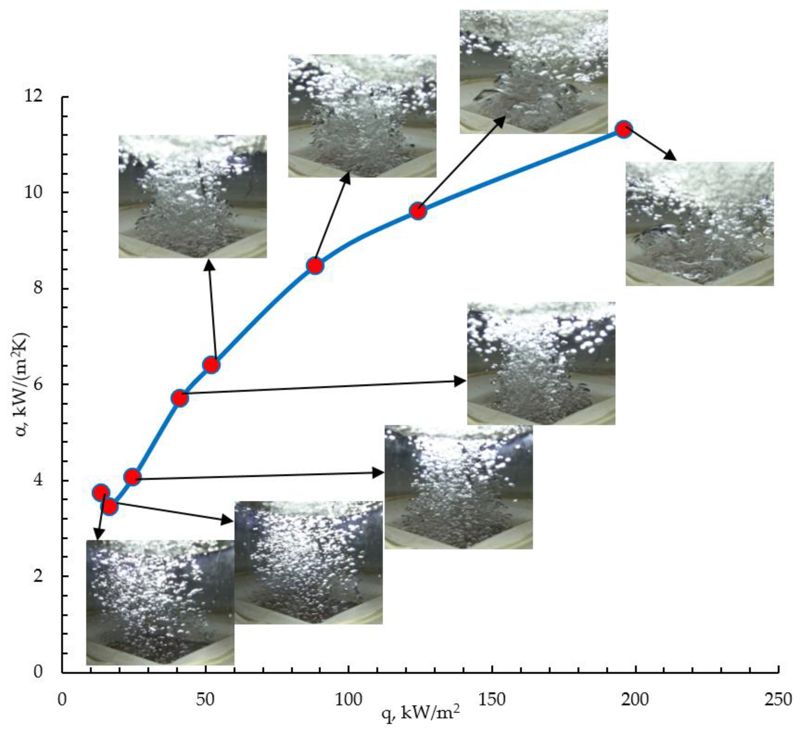
Figure 11 shows images of Novec-649 nucleate boiling on a surface with inclined minichannels, straight channels and a smooth surface, with increasing heat flux. The visualisation of boiling in conjunction with the dynamics of vapour bubble growth is important because it provides an opportunity to understand the heat transfer mechanism during boiling. For small overheats between the heating surface and the fluid, the vapour bubbles assume elliptical shapes. Some nucleation sites remain active at all times, producing vapour bubbles. A similar phenomenon related to the continuous activity of vertical channel outlets within the whole range of investigated heat fluxes was observed in [46,47]. Even before separation (horizontal coalescence) and after separation (vertical coalescence), the vapour bubbles begin to merge. Above a heat flux value of ~55 kWm−2, quantitative observations become impossible, due to the obscuration of the image by bubbles that combine to form vapour tunnels and large areas of irregular shapes, Figure 12. The images also show that for the same heat fluxes, there are more bubble nucleation centres for the extended surface. During the initial boiling phase, the bubbles are also significantly smaller.
4. Conclusions
Microchannel surfaces are easy and reproducible to produce using cavity machining and offer higher heat transfer coefficients than smooth surfaces. For the samples tested with microchannels, a significant increase in heat transfer was observed, with the heat transfer coefficient depending on the angle of inclination to the vertical and the width of the microchannel. For the surface with straight microchannels, an increase of 385% in the heat transfer coefficient was obtained compared to the smooth sample, reaching a value of 19.4 kWm−2K−1. The proposed surfaces, with microchannels 0.2 to 0.5 mm wide, angles to the vertical from 0° to 60° and depths of 0.3 mm allowed a critical heat flux of over 262 k Wm−2, more than twice the CHF for a reference smooth flat surface. The highest HTCs were obtained at the largest microchannel surface extensions, i.e., the surfaces with the smallest microchannel widths, which contributed to a significant number of active nucleation sites at their bottoms and lateral surfaces. The comparison of the boiling curves showed the influence of the width and the angle on the level of the microchannels on the boiling process. Experimental and theoretical studies related to growth rate modelling and the determination of vapour bubble diameters and detachment frequencies are planned.
Funding
This research received no external funding.
Data Availability Statement
The data presented in this study are available on request from the corresponding author.
Acknowledgments
This work was funded in part by the National Science Centre (grant No. 2021/05/X/ST8/01098). The author thanks M.E. Poniewski from the Warsaw University of Technology and T.M. Wójcik from the AGH University of Science and Technology for their scientific consultations in the selection of measuring devices.
Conflicts of Interest
The authors declare no conflict of interest.
Correction Statement
This work was funded in part by the National Science Centre (grant No. 2021/05/X/ST8/01098). The author thanks M.E. Poniewski from the Warsaw University of Technology and T.M. Wójcik from the AGH University of Science and Technology for their scientific consultations in the selection of measuring devices.
Nomenclature
| a | Width of specimen, m |
| b | Angle, ° |
| c | Specific heat, Jkg−1K−1 |
| Csf | Constant |
| CHF | Critical heat flux, W m−2 |
| d | Diameter, m |
| GWP | Global Warming Potential |
| g | Gravitational acceleration, m s−2 |
| HTC | Heat transfer coefficient, W m−2K−1 |
| h | Microchannel depth, m |
| i | Entalphy, J kg−1 |
| M | Molar mass, gmol−1 |
| q | Heat flux, Wm−2 |
| p | Pitch, m |
| p | Pressure, Pa |
| Ra | Roughness, μm |
| T | Temperature, K |
| w | Width, m |
| Greek letters | |
| α | Heat transfer coefficient, W m−2K−1 |
| ΔT | Superheat referred to the microfin base, K |
| δ | Thickness, m |
| ϕ | Angle of inclination, ° |
| λ | Thermal conductivity, W m−1 K−1 |
| μ | Dynamic viscosity, Pas |
| θ | Contact angle, ° |
| ρ | Density, kg/m3 |
| σ | Surface tension, N/m |
| υ | Kinematic viscosity, m2s−1 |
| Subscripts | |
| bs | Base |
| Cu | Copper |
| c | Critical |
| cyl | Cylinder |
| l | Liquid |
| MC | Microchannel |
| p | Constant pressure |
| sat | Saturated |
| Sn | Tin |
| T1, …, T8 | Thermocouple number |
| v | Vapour |
References
- Piasecka, M.; Strąk, K.; Maciejewska, B. Heat transfer characteristics during flow along horizontal and vertical minichannels. Int. J. Multiph. Flow 2021, 137, 103559. [Google Scholar] [CrossRef]
- Kaniowski, R.; Poniewski, M. Measurements of two-phase flow patterns and local void fraction in vertical rectangular minichannel. Arch. Thermodyn. 2013, 34, 3–21. [Google Scholar] [CrossRef]
- Najafizadeh, S.; Nadooshan, A.A.; Bayareh, M. Numerical study of air-water two-phase flow in a two-dimensional vertical helical channel. Fluid Dyn. Res. 2019, 52, 015501. [Google Scholar] [CrossRef]
- Chuang, T.J.; Chang, Y.H.; Ferng, Y.M. Investigating effects of heating orientations on nucleate boiling heat transfer, bubble dynamics, and wall heat flux partition boiling model for pool boiling. Appl. Therm. Eng. 2019, 163, 114358. [Google Scholar] [CrossRef]
- Surtaev, A.; Kuznetsov, D.; Serdyukov, V.; Pavlenko, A.; Kalita, V.; Komlev, D.; Ivannikov, A.; Radyuk, A. Structured capillary-porous coatings for enhancement of heat transfer at pool boiling. Appl. Therm. Eng. 2018, 133, 532–542. [Google Scholar] [CrossRef]
- Qu, Z.G.; Xu, Z.G.; Zhao, C.Y.; Tao, W.Q. Experimental study of pool boiling heat transfer on horizontal metallic foam surface with crossing and single-directional V-shaped groove in saturated water. Int. J. Multiph. Flow 2012, 41, 44–55. [Google Scholar] [CrossRef]
- Hu, H.; Zhao, Y.; Lai, Z.; Hu, C. Experimental investigation on nucleate pool boiling heat transfer characteristics on hydrophobic metal foam covers. Appl. Therm. Eng. 2020, 179, 115730. [Google Scholar] [CrossRef]
- Hu, H.; Zhao, Y.; Lai, Z.; Hu, C. Influence of surface wettability on pool boiling heat transfer on metal foam covers. Int. J. Therm. Sci. 2021, 168, 107069. [Google Scholar] [CrossRef]
- Xu, Z.G.; Zhao, C.Y. Thickness effect on pool boiling heat transfer of trapezoid-shaped copper foam fins. Appl. Therm. Eng. 2013, 60, 359–370. [Google Scholar] [CrossRef]
- Cooke, D.; Kandlikar, S.G. Effect of open microchannel geometry on pool boiling enhancement. Int. J. Heat Mass Transf. 2012, 55, 1004–1013. [Google Scholar] [CrossRef]
- Orman, Ł.J.; Radek, N.; Pietraszek, J.; Szczepaniak, M. Analysis of Enhanced Pool Boiling Heat Transfer on Laser—Textured Surfaces. Energies 2020, 13, 2700. [Google Scholar] [CrossRef]
- Orman, Ł.J.; Radek, N.; Kapjor, A.; Dębska, L. Pool boiling heat transfer performance of the surface modified with laser. MATEC Web Conf. 2022, 369, 02003. [Google Scholar] [CrossRef]
- Pastuszko, R. Pool boiling heat transfer on micro-fins with wire mesh—Experiments and heat flux prediction. Int. J. Therm. Sci. 2018, 125, 197–209. [Google Scholar] [CrossRef]
- Pastuszko, R.; Kaniowski, R.; Wójcik, T.M. Comparison of pool boiling performance for plain micro-fins and micro-fins with a porous layer. Appl. Therm. Eng. 2020, 166, 114658. [Google Scholar] [CrossRef]
- Jaikumar, A.; Kandlikar, S.G. Ultra-high pool boiling performance and effect of channel width with selectively coated open microchannels. Int. J. Heat Mass Transf. 2016, 95, 795–805. [Google Scholar] [CrossRef]
- Pastuszko, R. Pool boiling on rectangular fins with tunnel-pore structure. EPJ Web Conf. 2013, 45, 01020. [Google Scholar] [CrossRef]
- Gheitaghy, A.M.; Samimi, A.; Saffari, H. Surface structuring with inclined minichannels for pool boiling improvement. Appl. Therm. Eng. 2017, 126, 892–902. [Google Scholar] [CrossRef]
- Das, A.K.; Das, P.K.; Saha, P. Some investigations on the enhancement of boiling heat transfer from planer surface embedded with continuous open tunnels. Exp. Therm. Fluid Sci. 2010, 34, 1422–1431. [Google Scholar] [CrossRef]
- Shen, B.; Hamazaki, T.; Ma, W.; Iwata, N.; Hidaka, S.; Takahara, A.; Takahashi, K.; Takata, Y. Enhanced pool boiling of ethanol on wettability-patterned surfaces. Appl. Therm. Eng. 2019, 149, 325–331. [Google Scholar] [CrossRef]
- Kalani, A.; Kandlikar, S.G. Enhanced Pool Boiling With Ethanol at Subatmospheric Pressures for Electronics Cooling. J. Heat Transf. 2013, 135, 111002. [Google Scholar] [CrossRef]
- Ho, J.Y.; Wong, K.K.; Leong, K.C. Saturated pool boiling of FC-72 from enhanced surfaces produced by Selective Laser Melting. Int. J. Heat Mass Transf. 2016, 99, 107–121. [Google Scholar] [CrossRef]
- Forrest, E.; Buongiorno, J.; McKrell, T.; Hu, L.-W. Pool Boiling Performance of NovecTM 649 Engineered Fluid. ECI International Conference on Boiling Heat Transfer, Florianópolis, Brazil, 3–7 May 2009. [Google Scholar]
- Prabakaran, R.; Salman, M.; Kumar, P.G.; Lee, D.; Kim, S.C. Heat transfer and pressure drop characteristics of R1234yf during evaporation in a plate heat exchanger with offset strip fins: An experimental study. Int. J. Heat Mass Transf. 2022, 194, 123091. [Google Scholar] [CrossRef]
- Cao, Z.; Wu, Z.; Sundén, B. Pool Boiling of NOVEC-649 on Microparticle-Coated and Nanoparticle-Coated Surfaces. Heat Transf. Eng. 2021, 42, 1732–1747. [Google Scholar] [CrossRef]
- Cao, Z.; Wu, Z.; Sundén, B. Heat transfer prediction and critical heat flux mechanism for pool boiling of NOVEC-649 on microporous copper surfaces. Int. J. Heat Mass Transf. 2019, 141, 818–834. [Google Scholar] [CrossRef]
- Balaji, T.; Selvam, C.; Lal, D.M.; Harish, S. Enhanced heat transport behavior of micro channel heat sink with graphene based nanofluids. Int. Commun. Heat Mass Transf. 2020, 117, 104716. [Google Scholar] [CrossRef]
- Balaji, T.; Rajendiran, S.; Selvam, C.; Lal, D.M. Enhanced heat transfer characteristics of water based hybrid nanofluids with graphene nanoplatelets and multi walled carbon nanotubes. Powder Technol. 2021, 394, 1141–1157. [Google Scholar] [CrossRef]
- Kaniowski, R.; Pastuszko, R. Pool boiling experiment with Novec-649 in microchannels for heat flux prediction. Exp. Therm. Fluid Sci. 2023, 141, 110802. [Google Scholar] [CrossRef]
- Kaniowski, R.; Pastuszko, R. Pool Boiling of Water on Surfaces with Open Microchannels. Energies 2021, 14, 3062. [Google Scholar] [CrossRef]
- Kaniowski, R.; Pastuszko, R. Boiling of FC-72 on Surfaces with Open Copper Microchannel. Energies 2021, 14, 7283. [Google Scholar] [CrossRef]
- Nowakowski, L.; Skrzyniarz, M.; Blasiak, S.; Bartoszuk, M. Influence of the Cutting Strategy on the Temperature and Surface Flatness of the Workpiece in Face Milling. Materials 2020, 13, 4542. [Google Scholar] [CrossRef] [PubMed]
- Nowakowski, L.; Bartoszuk, M.; Skrzyniarz, M.; Blasiak, S.; Vasileva, D. Influence of the Milling Conditions of Aluminium Alloy 2017A on the Surface Roughness. Materials 2022, 15, 3626. [Google Scholar] [CrossRef]
- Hożejowska, S.; Kaniowski, R.; Pastuszko, R. Application of the Trefftz Method for Pool Boiling Heat Transfer on Open Microchannel Surfaces. Heat Transf. Eng. 2021, 43, 362–370. [Google Scholar] [CrossRef]
- Kumar, U.; Suresh, S.; Thansekhar, M.R.; Babu, D. Effect of diameter of metal nanowires on pool boiling heat transfer with FC-72. Appl. Surf. Sci. 2017, 423, 509–520. [Google Scholar] [CrossRef]
- Ribatski, G.; Jabardo, J.M.S. Experimental study of nucleate boiling of halocarbon refrigerants on cylindrical surfaces. Int. J. Heat Mass Transf. 2003, 46, 4439–4451. [Google Scholar] [CrossRef]
- Liao, L.; Bao, R.; Liu, Z. Compositive effects of orientation and contact angle on critical heat flux in pool boiling of water. Heat Mass Transf. 2008, 44, 1447–1453. [Google Scholar] [CrossRef]
- Kim, J.; Jun, S.; Laksnarain, R.; You, S.M. Effect of surface roughness on pool boiling heat transfer at a heated surface having moderate wettability. Int. J. Heat Mass Transf. 2016, 101, 992–1002. [Google Scholar] [CrossRef]
- Može, M.; Vajc, V.; Zupančič, M.; Golobič, I. Hydrophilic and Hydrophobic Nanostructured Copper Surfaces for Efficient Pool Boiling Heat Transfer with Water, Water/Butanol Mixtures and Novec 649. Nanomaterials 2021, 11, 3216. [Google Scholar] [CrossRef] [PubMed]
- Rohsenow, W.M. A Method of Correlating Heat Transfer Data for Surface Boiling of Liquids; M.I.T. Division of Industrial Cooporation: Cambridge, MA, USA, 1951. [Google Scholar]
- Cooper, M.G. Heat Flow Rates in Saturated Nucleate Pool Boiling-A Wide-Ranging Examination Using Reduced Properties. In Advances in Heat Transfer; Hartnett, J.P., Irvine, T.F., Eds.; Elsevier: Amsterdam, The Netherlands, 1984; Volume 16, pp. 157–239. [Google Scholar]
- Stephan, K.; Abdelsalam, M. Heat-transfer correlations for natural convection boiling. Int. J. Heat Mass Transf. 1980, 23, 73–87. [Google Scholar] [CrossRef]
- Kaniowski, R.; Pastuszko, R.; Kowalczyk, J.; Nowakowski, Ł. Bubble departure diameter determination for pool boiling on surface with microchannels. E3S Web Conf. 2018, 70, 02008. [Google Scholar] [CrossRef]
- Kowalczyk, J.; Madej, M.; Dzięgielewski, W.; Kulczycki, A.; Żółty, M.; Ozimina, D. Tribochemical Interactions between Graphene and ZDDP in Friction Tests for Uncoated and W-DLC-Coated HS6-5-2C Steel. Materials 2021, 14, 3529. [Google Scholar] [CrossRef]
- Zuber, N. Nucleate boiling. The region of isolated bubbles and the similarity with natural convection. Int. J. Heat Mass Transf. 1963, 6, 53–78. [Google Scholar] [CrossRef]
- Kandlikar, S.G. A Theoretical Model to Predict Pool Boiling CHF Incorporating Effects of Contact Angle and Orientation. J. Heat Transf. 2001, 123, 1071–1079. [Google Scholar] [CrossRef]
- Pastuszko, R.; Kaniowski, R. Boiling visualization on vertical fins with tunnel-pore structures. EPJ Web Conf. 2012, 25, 02019. [Google Scholar] [CrossRef]
- Kaniowski, R.; Pastuszko, R. Pool Boiling of Ethanol and FC-72 on Open Microchannel Surfaces. EPJ Web Conf. 2018, 180, 02042. [Google Scholar] [CrossRef]
Figure 1.
Test stand diagram.
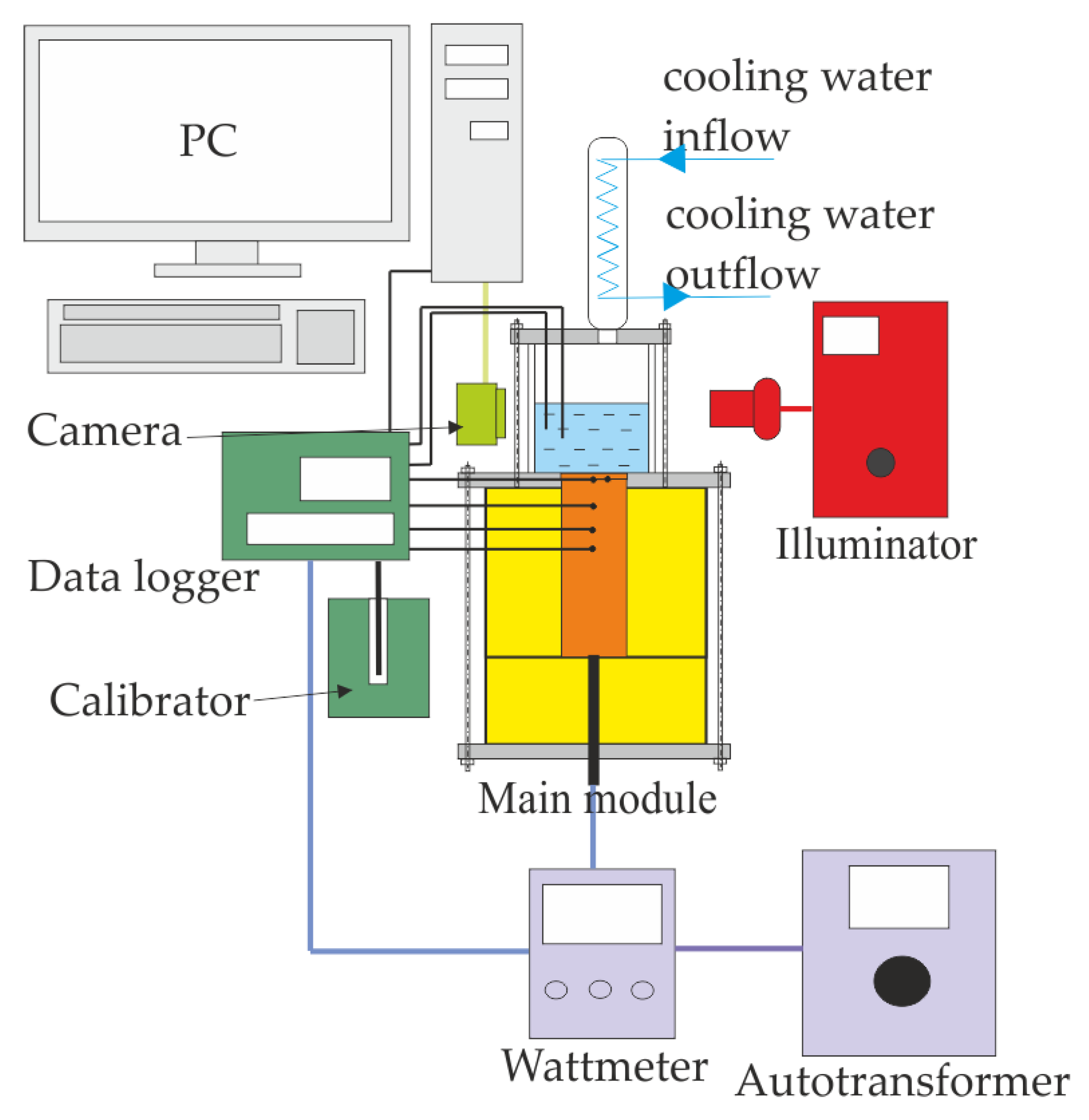
Figure 2.
Surface photographs: (a) MC-0.5-0.3-1.0-60; (b) MC-0.5-0.3-1.0-30; (c) MC-0.5-0.3-1.0; (d) smooth surface.
Figure 2.
Surface photographs: (a) MC-0.5-0.3-1.0-60; (b) MC-0.5-0.3-1.0-30; (c) MC-0.5-0.3-1.0; (d) smooth surface.
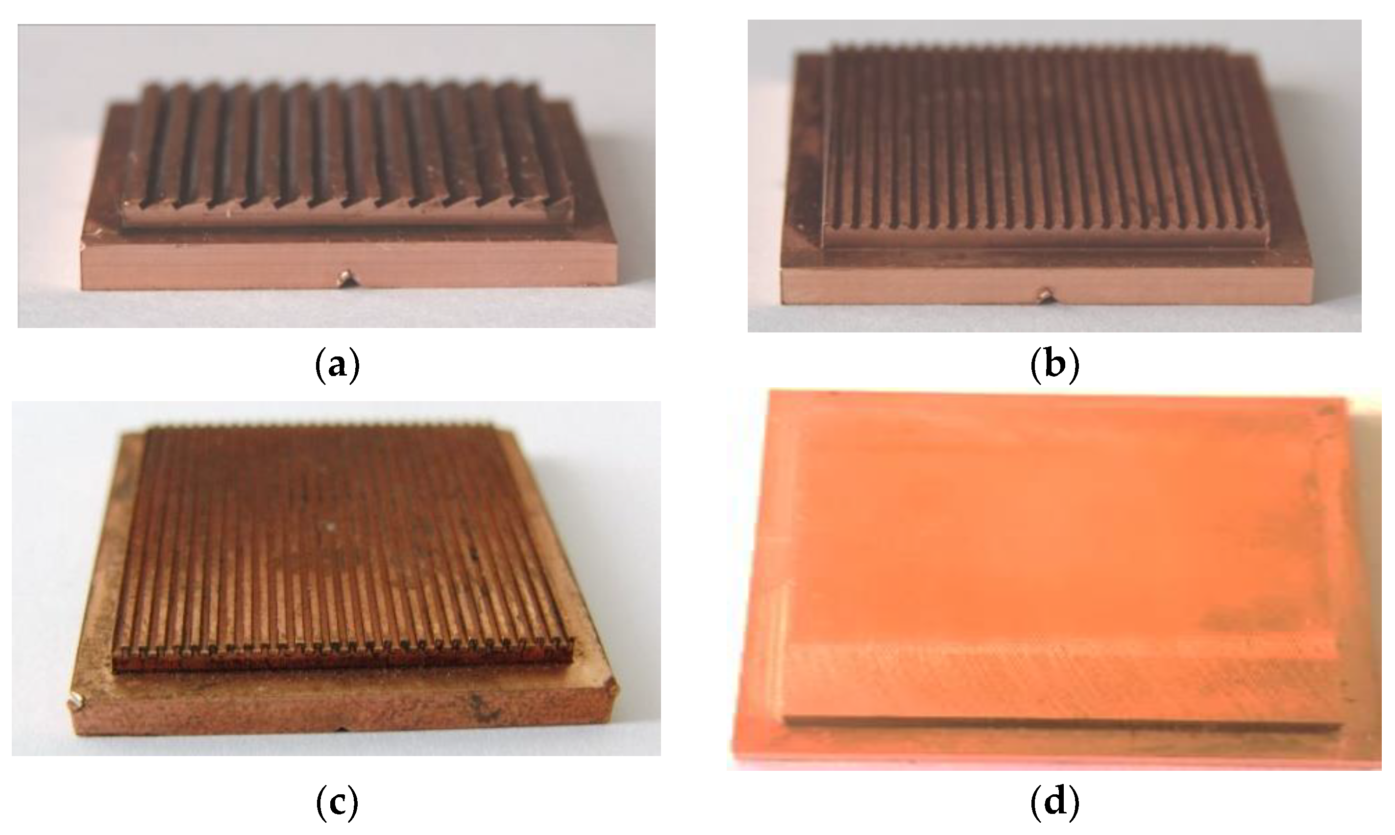
Figure 3.
Dimensions of characteristically tested surfaces.

Figure 4.
The arrangement of the temperature sensors on the test bench.

Figure 5.
Pool boiling curves for NOVEC-649, width of microchannel 0.2 mm. (a) Pool boiling heat transfer; (b) boiling curves.
Figure 5.
Pool boiling curves for NOVEC-649, width of microchannel 0.2 mm. (a) Pool boiling heat transfer; (b) boiling curves.

Figure 6.
Pool boiling curves for NOVEC-649, width of microchannel 0.3 mm. (a) Pool boiling heat transfer; (b) boiling curves.
Figure 6.
Pool boiling curves for NOVEC-649, width of microchannel 0.3 mm. (a) Pool boiling heat transfer; (b) boiling curves.


Figure 7.
Pool boiling curves for NOVEC-649, width of microchannel 0.4 mm. (a) Pool boiling heat transfer; (b) boiling curves.
Figure 7.
Pool boiling curves for NOVEC-649, width of microchannel 0.4 mm. (a) Pool boiling heat transfer; (b) boiling curves.
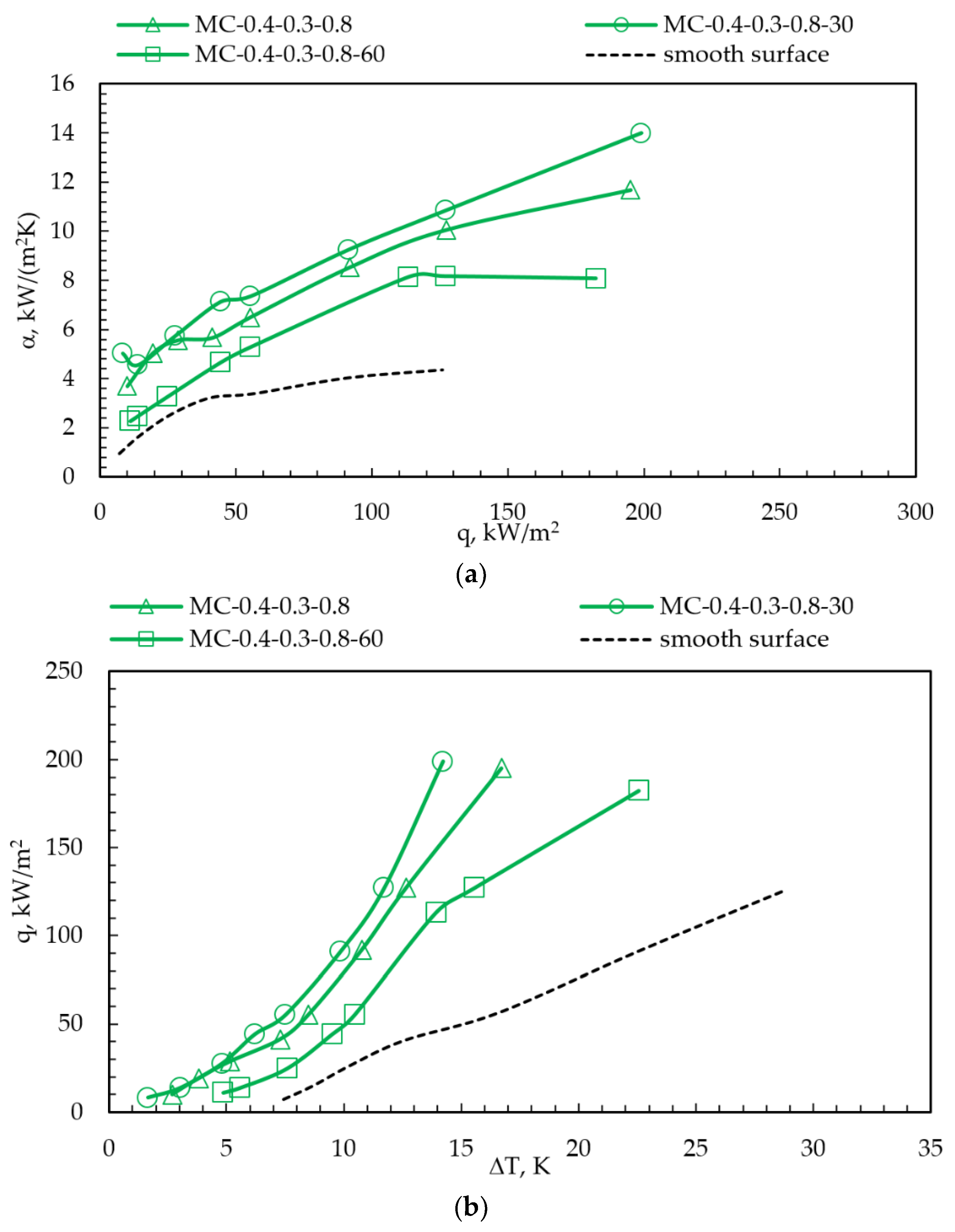
Figure 8.
Pool boiling curves for NOVEC-649, width of microchannel 0.5 mm. (a) Pool boiling heat transfer; (b) boiling curves.
Figure 8.
Pool boiling curves for NOVEC-649, width of microchannel 0.5 mm. (a) Pool boiling heat transfer; (b) boiling curves.
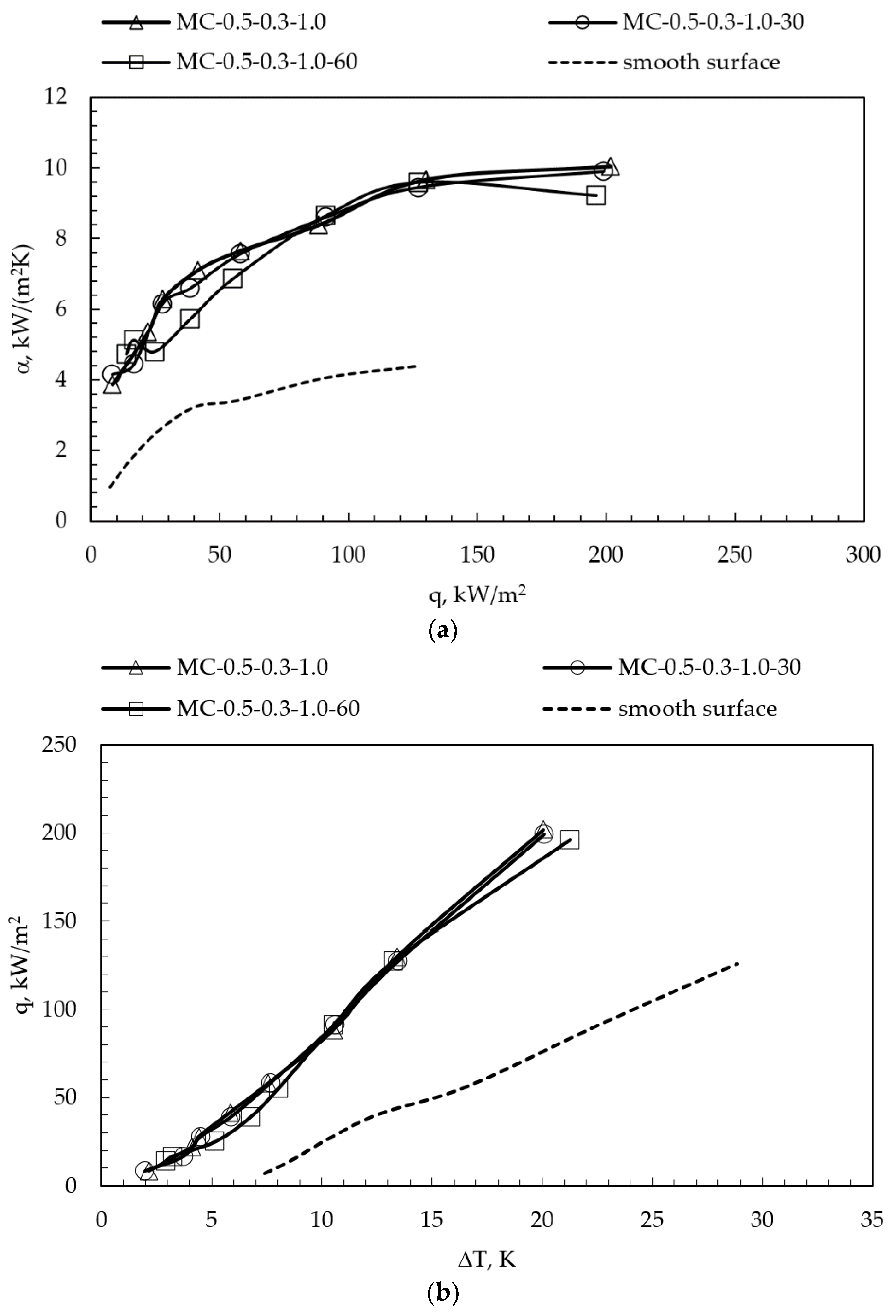
Figure 9.
Comparison of pool boiling curves for 0.3 mm wide microchannels with boiling curves from surfaces with microparticle coating (MPC) [25], nanoparticle coating (NPC) [25] and microporous coatings (electrochemical deposition method—ECDS) [24], and the surface of controlled chemical oxidation [38].
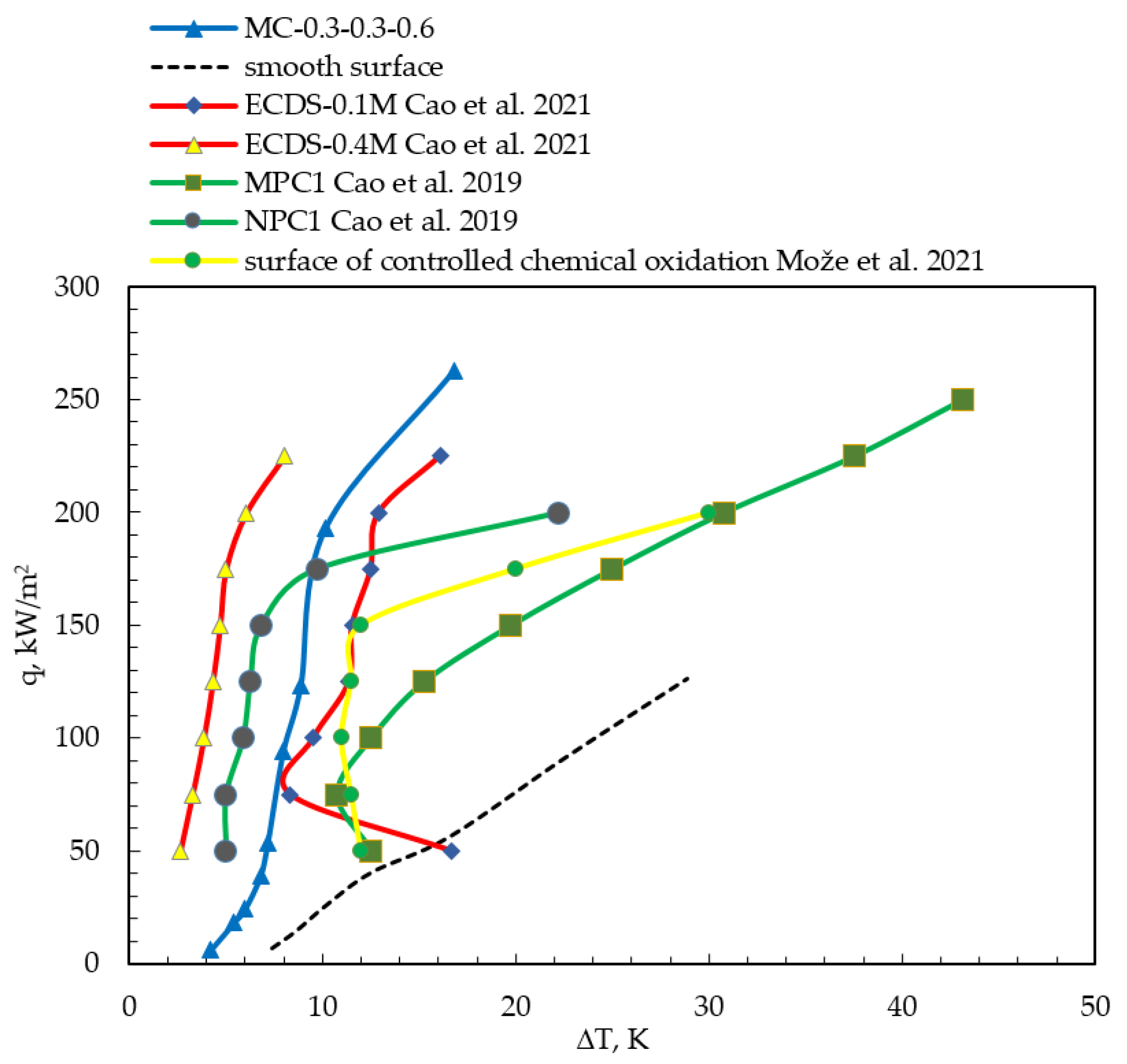
Figure 10.
Comparison of the experimental data to the correlations, plain surface. (a) Pool boiling heat transfer; (b) boiling curves.
Figure 10.
Comparison of the experimental data to the correlations, plain surface. (a) Pool boiling heat transfer; (b) boiling curves.

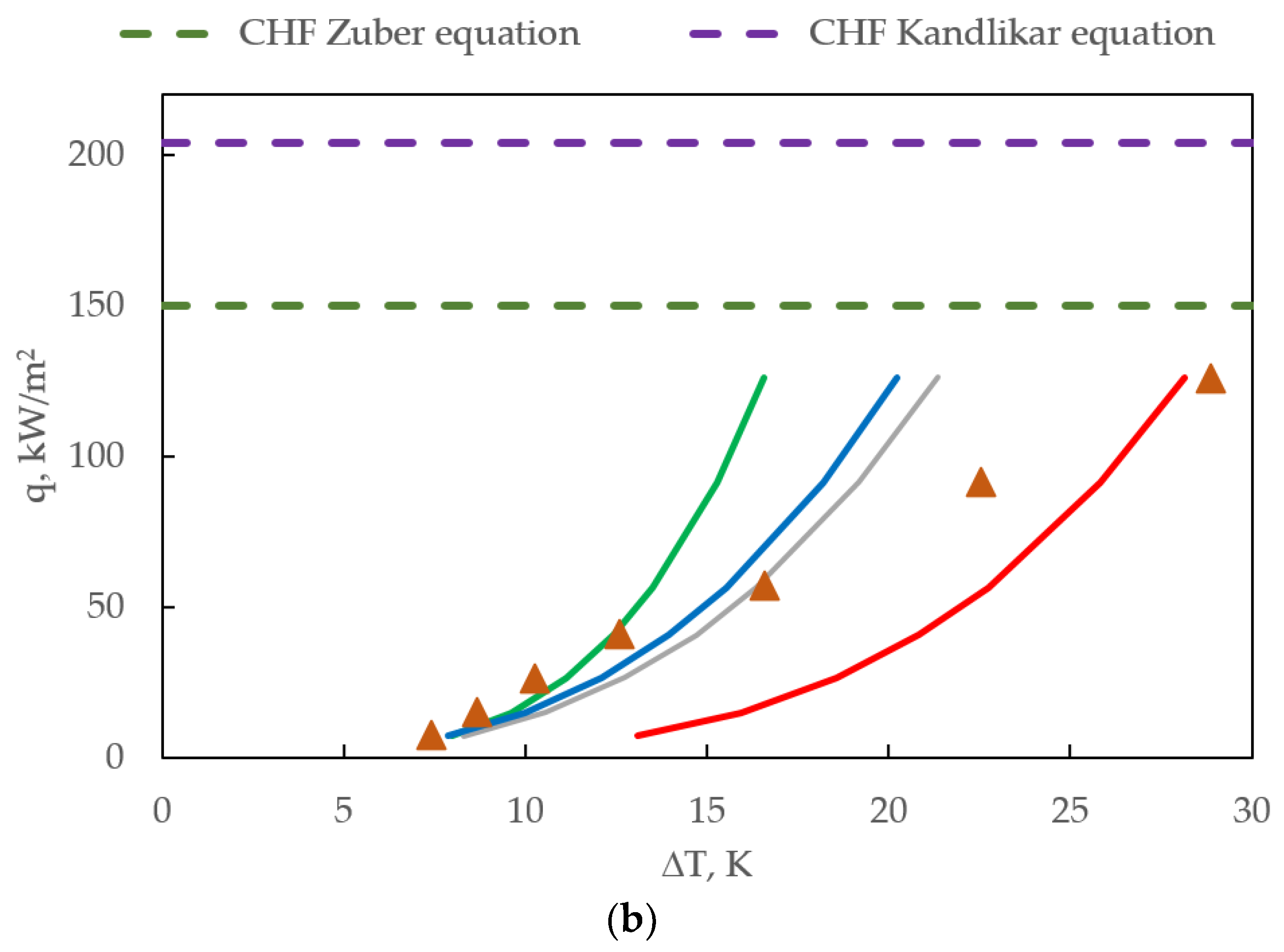
Figure 11.
Pool boiling visualization for a NOVEC-649 for smooth plain surface and surfaces with microchannels 0.3 mm wide.
Figure 11.
Pool boiling visualization for a NOVEC-649 for smooth plain surface and surfaces with microchannels 0.3 mm wide.
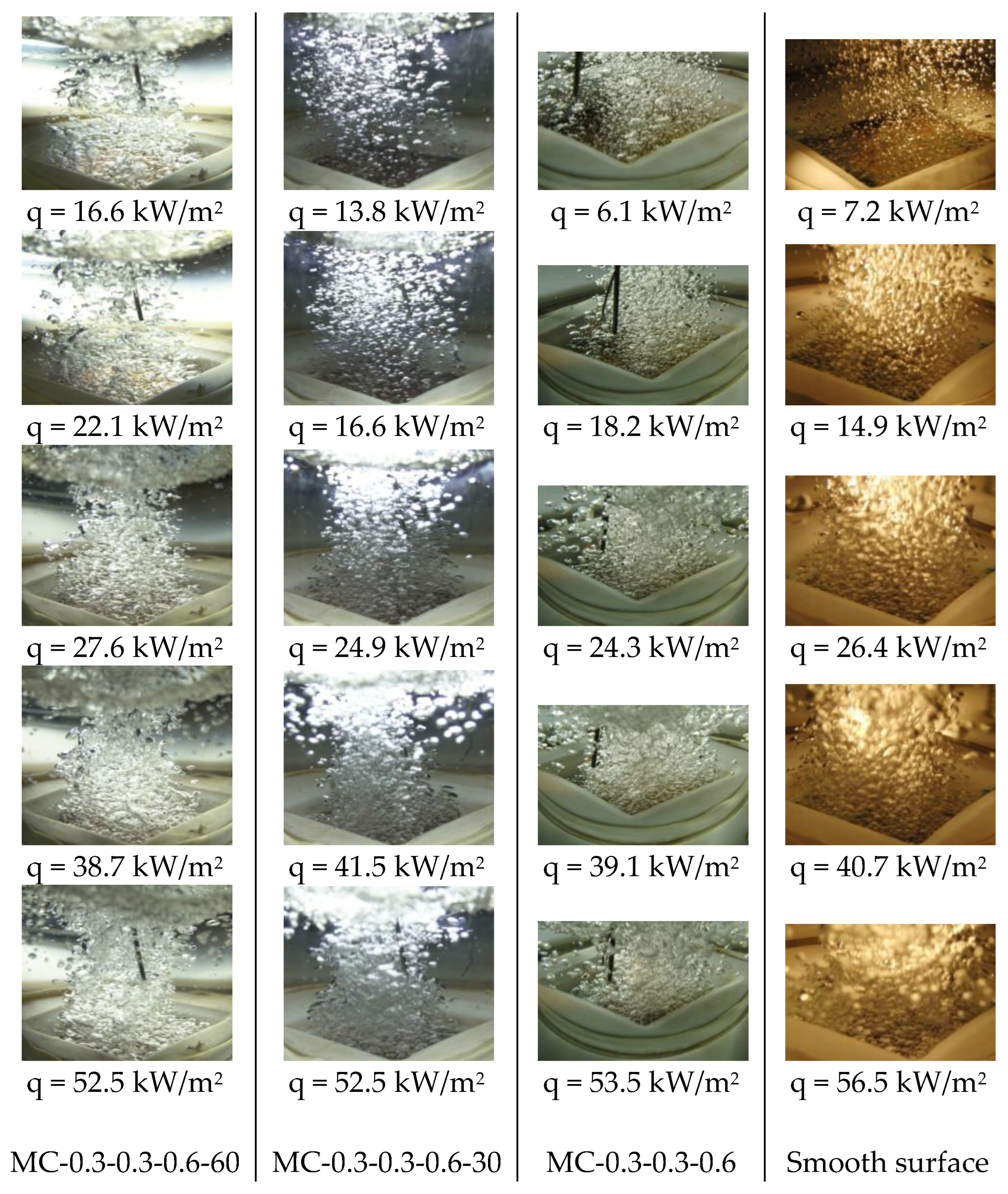
Figure 12.
Pool boiling curve visualization for surface with microchannels MC-0.3-0.3-0.6-30.

Table 1.
Surface codes and specifications.
| Specimen Code | w, mm | h, mm | p, mm | b, ° |
|---|---|---|---|---|
| MC-0.2-0.3-0.4 | 0.20 | 0.30 | 0.40 | 0 |
| MC-0.2-0.3-0.4-30 | 0.20 | 0.30 | 0.40 | 30 |
| MC-0.2-0.3-0.4-60 | 0.20 | 0.30 | 0.40 | 60 |
| MC-0.3-0.3-0.6 | 0.30 | 0.30 | 0.60 | 0 |
| MC-0.3-0.3-0.6-30 | 0.30 | 0.30 | 0.60 | 30 |
| MC-0.3-0.3-0.6-60 | 0.30 | 0.30 | 0.60 | 60 |
| MC-0.4-0.3-0.8 | 0.40 | 0.30 | 0.80 | 0 |
| MC-0.4-0.3-0.8-30 | 0.40 | 0.30 | 0.80 | 30 |
| MC-0.4-0.3-0.8-60 | 0.40 | 0.30 | 0.80 | 60 |
| MC-0.5-0.3-1.0 | 0.50 | 0.30 | 1.0 | 0 |
| MC-0.5-0.3-1.0-30 | 0.50 | 0.30 | 1.0 | 30 |
| MC-0.5-0.3-1.0-60 | 0.50 | 0.30 | 1.0 | 60 |
| Smooth surface | - | - | - | - |
Table 2.
Thermophysical properties of Novec-649.
| Parameters at 1013.25 hPa | Novec–649 |
|---|---|
| Tsat, K | 322.15 |
| ρl, kgm-3 | 1513 |
| ρv, kgm-3 | 13.42 |
| ilv, Jkg-1 | 88,000 |
| λl, Wm-1K-1 | 0.059 |
| σl, Nm-1 | 0.0108 |
| υl, m2s-1 | 0.0000003 |
| μl, Pas | 0.000454 |
| cpl, Jkg-1K-1 | 1103 |
| pc, kPa | 1880 |
| M, gmol-1 | 316 |
Disclaimer/Publisher’s Note: The statements, opinions and data contained in all publications are solely those of the individual author(s) and contributor(s) and not of MDPI and/or the editor(s). MDPI and/or the editor(s) disclaim responsibility for any injury to people or property resulting from any ideas, methods, instructions or products referred to in the content. |
© 2023 by the author. Licensee MDPI, Basel, Switzerland. This article is an open access article distributed under the terms and conditions of the Creative Commons Attribution (CC BY) license (https://creativecommons.org/licenses/by/4.0/).
Share and Cite
MDPI and ACS Style
Kaniowski, R. Pool Boiling of Novec-649 on Inclined Microchannel. Energies 2023, 16, 2476. https://doi.org/10.3390/en16052476
AMA Style
Kaniowski R. Pool Boiling of Novec-649 on Inclined Microchannel. Energies. 2023; 16(5):2476. https://doi.org/10.3390/en16052476
Chicago/Turabian StyleKaniowski, Robert. 2023. "Pool Boiling of Novec-649 on Inclined Microchannel" Energies 16, no. 5: 2476. https://doi.org/10.3390/en16052476
Note that from the first issue of 2016, this journal uses article numbers instead of page numbers. See further details here.