Perspective

Hydrogen Application as a Fuel in Internal Combustion Engines

Department of Industrial Engineering (DIN), University of Bologna, 40136 Bologna, Italy
*
Author to whom correspondence should be addressed.
Energies 2023, 16(6), 2545; https://doi.org/10.3390/en16062545
Submission received: 14 February 2023 / Revised: 2 March 2023 / Accepted: 6 March 2023 / Published: 8 March 2023
(This article belongs to the Section I2: Energy and Combustion Science)

Abstract

:
Hydrogen is the energy vector that will lead us toward a more sustainable future. It could be the fuel of both fuel cells and internal combustion engines. Internal combustion engines are today the only motors characterized by high reliability, duration and specific power, and low cost per power unit. The most immediate solution for the near future could be the application of hydrogen as a fuel in modern internal combustion engines. This solution has advantages and disadvantages: specific physical, chemical and operational properties of hydrogen require attention. Hydrogen is the only fuel that could potentially produce no carbon, carbon monoxide and carbon dioxide emissions. It also allows high engine efficiency and low nitrogen oxide emissions. Hydrogen has wide flammability limits and a high flame propagation rate, which provide a stable combustion process for lean and very lean mixtures. Near the stoichiometric air–fuel ratio, hydrogen-fueled engines exhibit abnormal combustions (backfire, pre-ignition, detonation), the suppression of which has proven to be quite challenging. Pre-ignition due to hot spots in or around the spark plug can be avoided by adopting a cooled or unconventional ignition system (such as corona discharge): the latter also ensures the ignition of highly diluted hydrogen–air mixtures. It is worth noting that to correctly reproduce the hydrogen ignition and combustion processes in an ICE with the risks related to abnormal combustion, 3D CFD simulations can be of great help. It is necessary to model the injection process correctly, and then the formation of the mixture, and therefore, the combustion process. It is very complex to model hydrogen gas injection due to the high velocity of the gas in such jets. Experimental tests on hydrogen gas injection are many but never conclusive. It is necessary to have a deep knowledge of the gas injection phenomenon to correctly design the right injector for a specific engine. Furthermore, correlations are needed in the CFD code to predict the laminar flame velocity of hydrogen–air mixtures and the autoignition time. In the literature, experimental data are scarce on air–hydrogen mixtures, particularly for engine-type conditions, because they are complicated by flame instability at pressures similar to those of an engine. The flame velocity exhibits a non-monotonous behavior with respect to the equivalence ratio, increases with a higher unburnt gas temperature and decreases at high pressures. This makes it difficult to develop the correlation required for robust and predictive CFD models. In this work, the authors briefly describe the research path and the main challenges listed above.

1. Hydrogen Behavior as a Fuel: Advantages

Hydrogen is recognized as the energy vector that will lead us to the mobility of the future, which will be free of fossil fuels. Hydrogen is the only fuel potentially free of carbon, carbon monoxide and carbon dioxide emissions: it allows high efficiencies and low emissions of nitrogen oxides (NOx) [1,2]. The hydrogen-powered ICE is the only known internal combustion engine capable of meeting future EU regulations. Hydrogen has the characteristics of a highly efficient burning rate [1,2], as it has wide flammability limits (under normal conditions, 4% to 75% by volume) and a high flame propagation rate (5 to 8 times superior to gasoline). Hydrogen provides a stable combustion process for lean and very lean mixtures, which in turn reduces nitrogen oxides emissions (the only polluting emissions for this type of engine supply) [2,3]. Furthermore, again thanks to the highly dilute mixtures and the high autoignition temperature, the hydrogen engine tolerates higher compression ratios (up to 14.5:1) than the gasoline engine [2,4], which leads to greater thermodynamic efficiency [5]. Thus, the engine can be operated through load quality regulation, i.e., without throttle, which can lead to an engine efficiency of 52% [6].

2. Hydrogen Behavior as a Fuel: Criticalities

Close to the stoichiometric air-to-fuel ratio, due to the above-mentioned properties, hydrogen-fueled engines exhibit abnormal combustion, such as spontaneous ignition during the intake stroke (backfire), premature uncontrolled ignition (pre-ignition) and self-ignition of the end-gas region or excessive flame rates (knock) [6,7]. Suppressing abnormal combustions in hydrogen-fueled engines has proven quite challenging. According to Verhelst et al. [6], the low ignition energy of hydrogen is often too quickly identified as the major cause of backfire because the ignition by thermal masses (valves, for example) is more related to the autoignition temperature of the mixture, which is very high. Additionally, deposits and particulate matter, which are believed to function as hot spots, have extremely low concentrations in hydrogen engines. Instead, the authors believe that the reduced quenching distance, together with the wide flammability limits, and the consequent combustion in piston top land, is a parameter too often neglected by researchers. Therefore, the reasons behind the spontaneous and uncontrolled ignition of hydrogen are still being debated.

3. Comparison between Hydrogen and Other Fuels for ICE Applications

Hydrogen is not the only alternative fuel useful for the energy transition of sustainable mobility, but it is the one of greatest interest due to its characteristics in relation to its application in ICEVs. Therefore, before going into the details of the problems associated with hydrogen engines, this paragraph provides a brief comparison between hydrogen and other reference fuels used in classic spark ignition engines (gasoline, diesel, methane) or for the transition towards mobility with zero polluting emissions (including CO2), such as ammonia and biofuels. Table 1 shows a comparison of the main properties of diesel, gasoline, hydrogen, ammonia and methane [8,9,10]. As seen in Table 1, ammonia has the highest autoignition temperature, so it is difficult to ignite.
In Cardoso et al. [10], the authors reported that both ammonia and hydrogen have great potential to be carbon-free. Hydrogen is generating significant expectations as an enabler of a carbon-free economy, but issues with storage, distribution, and infrastructure deployment are delaying its full implementation. Ammonia, on the other hand, represents a highly efficient energy vector: contrary to hydrogen, it benefits from being a liquid fuel, bringing high flexibility of its supply. Furthermore, ammonia can be used both as a fuel and as a hydrogen enabler. Combustion of pure ammonia in ICEs is a challenging task, mainly due to its high autoignition temperature, narrow flammability range (16–25% by volume in air), low flame speed and high heat of vaporization [11], which result a power output reduction of about 20% compared to conventional gasoline [12]. To overcome these disadvantages, ammonia can be blended with conventional hydrocarbon fuels or even hydrogen to increase the flammability of the mixture while reducing carbon emissions. Finally, an ammonia engine would suffer from a high NOx emission rate—much higher than those of hydrogen engines.
Agarwal et al. [13] reviewed the characteristics of some biofuels, including biodiesel. The primary resources for biodiesel production are non-edible oils. Biodiesel can be blended in any proportion with mineral diesel to create a biodiesel blend or can be used in its pure form. Like petroleum diesel, biodiesel runs in a compression ignition engine and requires very little or no engine modifications because biodiesel has properties similar to mineral diesel. It can be stored like petroleum diesel and requires no separate infrastructure. The use of biodiesel in conventional diesel engines substantially reduces the emission of unburned hydrocarbons, carbon monoxide and particulate matter, but causes a slight increase in NOx emissions [14,15]. Therefore, it can be a short-term alternative to petroleum diesel but not in the long-term, when CO2 emissions from engine exhausts need to be zero.
Hydrogen can also be used blended with another fuel in ICEVs. However, this application is not relevant to the scope of the document, which focuses on the use of hydrogen as the sole fuel in vehicles powered by spark ignition engines.

4. Design of the Hydrogen Fueled Engine: Main Challenges

The main challenges in using hydrogen as a primary fuel in ICEs are:
  • Low energy per unit volume (related to the low density of hydrogen gas), requiring the adoption of high-pressure storage tanks (commonly 700 bar) [3].
  • High flammability range (equivalence ratio in air from 0.1 to 7.1) and very low minimum ignition energy [2,5]—an order of magnitude lower than those of fossil-fuel–air mixtures at stoichiometric ratios. Both of these features, which can be major benefits in terms of fuel economy, could induce combustion control problems (pre-ignition and detonation) because they expose the engine to uncontrolled ignition due to hot spots and hot gases, which act as ignition sources. The adoption of hydrogen direct injection (DI) solves the problem of pre-ignition in the intake manifold, but the risk of detonation remains in the cylinder due to the high speed of the flame, and therefore, the high rate of pressure increase in the cylinder during combustion [2,8].
  • Very high laminar flame speed (LFS), from 3 to 5 times that of gasoline, in a wide range of equivalence ratios (from 0.5 to 3.5). The combustion of hydrogen is almost isochore for the stoichiometric air-to-fuel ratios (the effective cycle is close to the thermodynamically ideal engine cycle in stoichiometric air-fuel conditions): the need for reducing and control the development of the combustion flame imposes a maximum equivalence ratio value in air of 0.6 [2], which reduces nitrogen oxides emissions and distances pre-ignition (more accentuated at the stoichiometric level), while also improving fuel economy.
  • Very low quenching distance: hydrogen flames travel closer to the cylinder wall before extinguishing than other fuels [3]. They are relatively short-lived, as they ignite rapidly [2]. This significantly impacts the combustion in the gaps between the cylinder and piston and increases the evaporation of the lubricant (oil particulate formation).
  • High diffusivity, which improves the homogenization of the mixture but makes it difficult to stratify the mixture [16].
Therefore, engine research faces some critical issues before we can adopt hydrogen as the primary fuel in ICEs. The main drawbacks are the high NOx emissions (which mainly depend on the spark timing and the homogeneity/stratification of the mixture [3]) and low power output: several research efforts have been conducted by many authors to establish the relationship among NOx, air-to-fuel ratio and spark timing for engines fueled only by hydrogen [17,18] or fueled with the addition of hydrogen [19]. However, it is worth mentioning that the experimental analysis on hydrogen-fueled systems is crucial and limited to some operating/environmental conditions, mainly with very narrow ranges, and research engines or engines specifically designed to run on pure hydrogen [18]. BMW has been working on a bi-fuel engine (gasoline plus hydrogen) [20] but reduced the compression ratio to 9.5 to allow the gasoline engine to run on hydrogen. The load control strategy was the most experimentally studied element, determining the additional NOx emissions and engine efficiency. Load is commonly governed by quantitative control (no throttle) instead of quantitative control (typical of spark ignited engines) when possible. Limitations to unthrottled operation are misfire with a very low load (idling) and NOx emissions [6].
Therefore, to design an engine powered only by hydrogen today and functioning in the entire operating range of interest, the current challenges cannot be met without a deep understanding of the physical phenomena related to hydrogen’s use as a pure fuel in ICEs because the experiments are intrinsically limited. Three-dimensional CFD simulations could facilitate the development and optimization of these engines. Computer simulations calculate the flame propagation of hydrogen by monitoring its development in the combustion chamber and resolving the pressure and temperature within the cylinder. To do this, the prediction of the laminar burn rate of the air–hydrogen mixture inside the cylinder at the local pressure and temperature is crucial.
To summarize, the most important elements to address are:
  • Defining the chemical properties of hydrogen (LFS and ignition delay time (IDT)) to correctly predict the initiation and development of the hydrogen flame in the combustion chamber under typical operating conditions of a real engine.
  • Injection of hydrogen gas.
  • Ignition system: a suitable ignition system could be adopted to prevent autoignition of the hydrogen-based mixture due to hot spots on/around the spark plug [21].
  • Oil–fuel dilution must be simulated to prevent oil particulate formation.

5. Definition of the Chemical Properties of Hydrogen-Based Mixtures

For correctly reproducing the hydrogen ignition and combustion processes in an ICE with the hazards related to pre-ignition and knocking combustion, 3D CFD simulations could be of great help. Combustion processes in engine conditions are highly turbulent. Flame velocity is often estimated from a functional relationship involving the LFS, which is provided as input to CFD codes in the form of lookup tables or correlations, both of which must be based on experimental data, or if the latter are not available, on multi-step chemical models. Alongside the LFS estimate, it is necessary to predict the IDT trend to model the possible autoignition of the air–hydrogen mixture at the high thermal loads typical of these engines in stoichiometric or close to stoichiometric conditions.
In the literature, experimental data are scarce on air–hydrogen mixtures, particularly at engine-like conditions, because they are complicated by flame instabilities at pressures similar to those of the engine. From a computational point of view, flame instabilities can be avoided by assuming a one-dimensional, planar flame [22]. Flame speed exhibits a non-monotonic behavior-to-equivalence ratio, increases with unburnt gas temperature and decreases at elevated pressures [23], making further correlation development difficult. Therefore, the development of the correlation for the hydrogen–air system is hampered by two main problems:
(i).
The performance of the correlation cannot be verified experimentally, since hydrogen flames are unstable at high pressures. However, the hypothetical stable flame speeds predicted by the kinetic model serve as reasonable estimates for the design codes of the engine.
(ii).
The pressure-dependence of the hydrogen kinetics is extremely complex, and the correlations available in the literature often fail to adequately capture the modeled data due to inadequate functional formulation.
As a result, differences between kinetic model predictions and correlation estimates are often greater than ±20% [23].
To predict LFS and IDT behaviors, the commonly adopted methodology is as follows:
  • The experimental measurement of the LFS is limited to pressure and temperature conditions far from those typical of an internal combustion engine:
    • Pressure and temperature values normally close to the ambient.
    • A few experiments used pressures of up to 10 bar and temperatures of up to 400 K [23].
  • Hydrogen-based mixtures are unstable at high pressures, and the pressure-dependence of hydrogen kinetics is complex [22,23]. Thus, validation of reaction mechanisms is very limited at best. Flame instability makes accurate burning velocity measurements at lean conditions almost impossible.
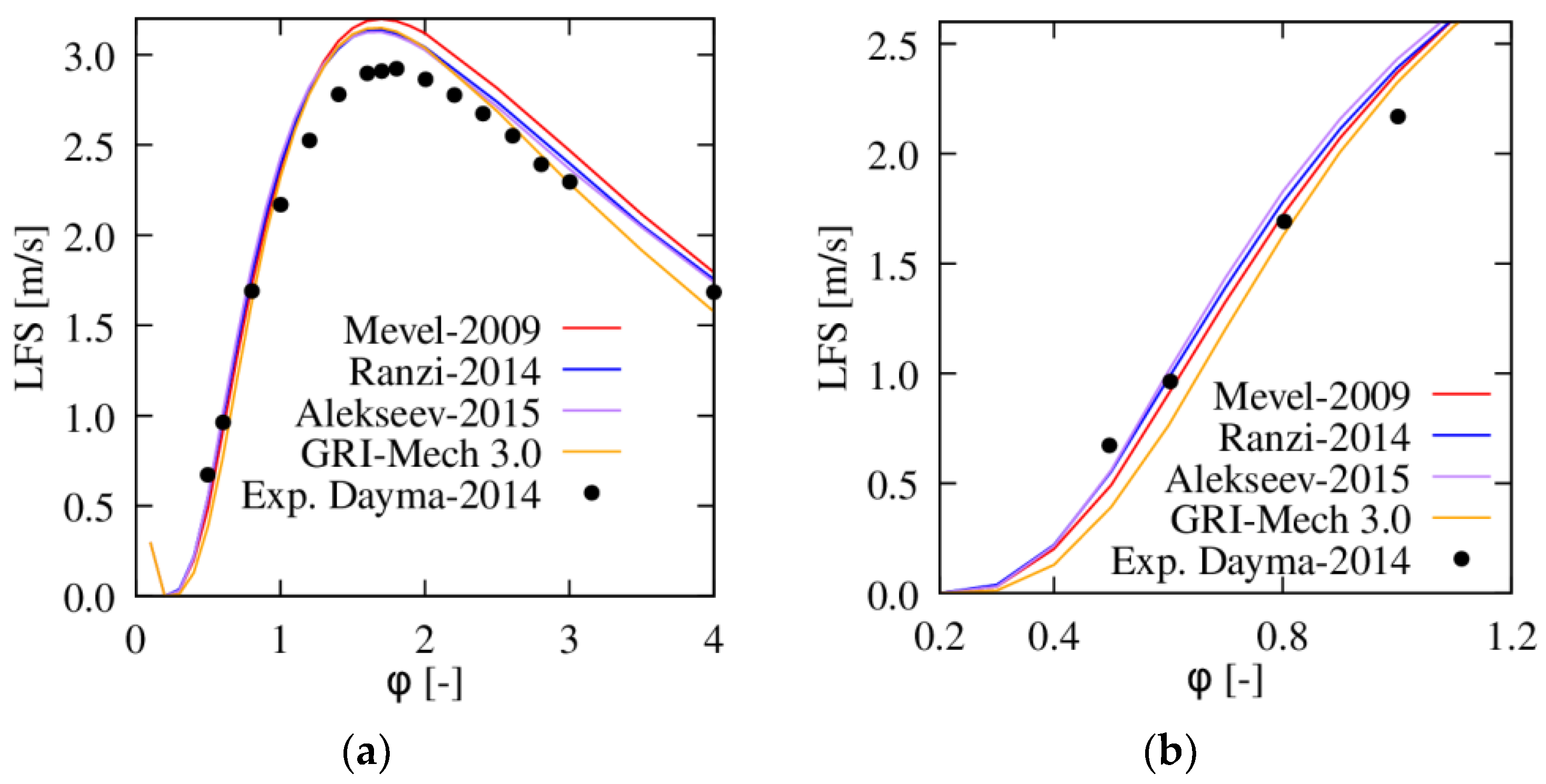
  • In Figure 1a, the authors verified the effectiveness of different kinetic schemes [24,25,26] at reproducing the experimental data available in [27] obtained at 1 bar and 303 K. Only under lean conditions (see Figure 1b) did the various schemes substantially agree with the experimental results [27]. In addition, it is worth mentioning that, in general, a wide range of experimental results are available in the literature due to the influence of the flame-stretching rate on the experimentally observed burning rates [22,28], which accelerates the flame or increases its speed: by definition, the laminar flame velocity must be at a zero flame-stretch rate.
  • An alternative solution is to test reaction mechanisms based on autoignition times measured in shock tubes, as suggested by Verhelst et al. [22].
  • For the same reason just explained, the IDT measurement is often performed at low pressures (a few bars) or with very dilute mixtures (usually in argon rather than in air). In some cases, as in [23], the performance of the kinetic model at elevated pressures could be evaluated by ignition delay times from shock-tube experiments when stable flame rate data could not be obtained. As for LFS, the IDT is a function of the chemical and physical properties of the mixture itself. Hydrogen has IDT values that drastically reduce at a temperature of around 1000 K (see Figure 2b, where the IDT drops by at least three orders of magnitude at 1200 K compared to the values obtained at 900 K in Figure 2a). This is a critical element in combustion because the high flame speed of hydrogen induces very rapid, almost isochore combustion. Therefore, the in-cylinder charge reaches high-temperature values, and the risk of abnormal combustion becomes very high.
  • Outside these fields, measurement is replaced by calculation using complex kinetic schemes, validated on the previously mentioned experimental tests. The validation of the kinetic scheme is limited to the available experimental range.
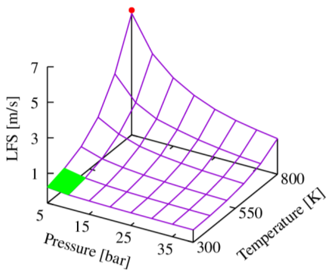
  • Once validated (in a very limited range of pressure and temperature), the chemical kinetic calculations allow one to extrapolate the “engine points” in the working space of pressure, temperature and effective composition of the mixture. The kinetic scheme adopted here is that of Mevel et al. [26]. In Figure 3, the LFS is plotted as a function of pressure and temperature values, in ranges of interest for engine applications, for an equivalence ratio of 0.5. The green square shows the range of experimentally tested pressure and temperature values. At the same time, the red point indicates a possible pressure–temperature point of interest typical of engine applications (data extrapolated after validation of the kinetic scheme). There is no certainty about the goodness of the results extrapolated outside the experimental range, as previously explained.
  • Finally, the results of the chemical kinetic computations under engine-type conditions are estimated by correlations [23] or look-up tables, which will be inserted into the 3D CFD codes. The estimation process is non-trivial, and efforts must be made to define correlations capable of reproducing the results of the chemical kinetic simulation under a wide range of engine-like conditions.
Thus, the chemical properties of hydrogen can be derived from experiments, which are used to validate the chemical kinetic schemes under very narrow ranges of operating conditions. The actual points of interest for ICE applications are then extrapolated from the kinetic schemes, from which are derived correlations to be inserted into 3D CFD codes. Another solution is to run detailed run-time simulations of the chemistry, but they are time-consuming and do not solve the problems faced.

6. Gas Injection

The development of SI engines fueled by hydrogen has been studied over the years experimentally (on optical research engines or injection chambers in a controlled environment) [30,31,32,33] and computationally by various groups of researchers [30,34,35,36,37]. Numerical studies on direct-injection hydrogen engines are minimal, mainly due to the complexity of modeling the physical phenomena associated with the high velocity gas jet. In the case of port fuel injection (PFI) engines, the power that can be generated is less than that generated using DI engines due to the low hydrogen density (high occupied volume), and therefore, the smaller volume available for fresh air in the duct (stoichiometrically 29.52% hydrogen in the air by volume [16]). Additionally, PFI engines are more prone to backfiring and pre-ignition in the intake manifold. For these reasons, today’s trend is towards hydrogen-fueled DI engines (the hydrogen is injected after the intake process), in which the degree of homogeneity or stratification of the mixture at the ignition time can be adjusted by various DI strategies. Typically, high pressures are applied for DI fueling to achieve high fuel mass flow and consequently rapid fuel–air mixing, particularly with late injection strategies. High injection pressures cause turbulent under-expanded fuel jets to form after the fuel leaves the nozzle. Consequently, fundamental understanding of the gas dynamics and sonic/mixing characteristics of the under-expanded jets formed by hydrogen injection from the nozzle holes is imperative for the development of new and more efficient high-pressure DI gas-fueled engines [37]. The 3D CFD simulation of internal mixture formation and combustion helps to understand complex cylinder processes and provides a powerful tool for optimizing the engine’s working cycle. The know-how gained from the formation of fossil fuel mixture and from the combustion process cannot be transferred directly to the DI-H2. Great care must be taken in the CFD code to correctly describe not only the jet penetration but also the mixing between the injected fuel and the surrounding gas. A major influence on the mixing process comes from the characteristics of the under-expanded region, where the flow is supersonic.
For DI-H2 ICEs, the main challenge consists in properly controlling both geometrical and operational injection parameters, which need to be correctly set to achieve the proper mixture stratification/homogenization in the combustion chamber at spark creation. The injector design has a significant influence on the performance of the DI-H2 combustion process. The actuation time, the injection pressure, and the arrangement of the injector tip and the injector housing on the engine head affect the stratification/homogenization of the cylinder charge, on which efficiency and emissions strongly depend.
Therefore, DI-H2 engine research has focused on advanced injector design and injection strategies. In this scenario, the development of a numerical approach can provide a significant contribution to the experimental tests. A numerical approach can never replace accurate engine testing. The significant potential of a modeling approach lies in exploring new settings and geometries and optimizing the best solutions. Through CFD models have been validated against experimental data, innovative technological solutions can be numerically tested and produced only in cases of a positive response. The correct settings of the mesh and turbulence model allow reaching a remarkable agreement between numerical and experimental data in terms of fuel-jet evolution and mixture formation [30,34]. The grid resolution is found to significantly influence jet penetration and has almost no effect on fuel dispersion. Fundamental understanding of the interaction between hydrogen’s in-cylinder jets and in-cylinder air flow is essential for optimizing mixture formation and normal or boosted intake combustion processes. Investigations should be carried out to evaluate whether it makes sense to design less permeable “tumbling ducts” when the main motion in the cylinder is destroyed by the injection of hydrogen at 1200 m/s: the injection event destroys the organized motion generated in the cylinder by the intake process [30].
Most numerical simulations are performed using the Reynolds-averaged Navier–Stokes (RANS) technique, which has been shown to still represent the best compromise between simulation time and result quality compared to the large-eddy simulation (LES) technique [37]. The most complex modeling part is related to the sonic/supersonic region and the jet-to-jet interaction. A multi-hole nozzle creates an intense jet-to-jet interaction, with all jets merging into a single jet immediately downstream of the under-expanded region. This phenomenon (Coanda effect) is even more challenging for numerical simulation and requires a higher level of detail in numerical simulation and grid resolution, especially regarding the fields near the injector nozzle [31]. The Coanda effect could modify the dynamics of the impact on the wall and the formation of the mixture. To simulate and capture this phenomenon, the grid resolution, computational time-step, discretization scheme, and turbulence model must be set correctly.
With reference to the sonic region, it occurs when the ratio between the injection pressure and the ambient pressure is higher than the critical ratio (1.889 for hydrogen). At the nozzle outlet, a supersonic region (Ma > 1) is visible, where the pressure passes from the injector to the ambient conditions through a series of shocks along the direction of the jet. When the jet is highly under-expanded (high injection pressure), the recompression occurs through a large Mach disk where the flow changes from highly supersonic (Ma >> 1) to subsonic (Ma < 1). A subsonic region is formed downstream of the Mach barrel region, where the mixing process usually occurs. This phenomenon can be experimentally visioned in ad hoc optical chambers and reproduced in equivalent simple volumes. Very fine meshes and low time steps must be adopted to capture such a domain. In engine applications, to reduce the complexity of such flow simulation, a gas injection model can be used to avoid supersonic flow and shock wave simulation [38]. Only the flow at the downstream of the Mach disk is modeled by a suitable boundary at its location, assuming complete mixing between air and fuel. The process between the nozzle outlet and the Mach disk is assumed to be isothermal, and there is no flow through the barrel shock. The size of the Mach disk is assigned as the new nozzle diameter, and therefore, the velocity at the exit of the new nozzle is sonic. This approach saves computational time, but the interaction between the flow field and the very high-speed jet (1200 m/s) is lost. Additionally, if the jet is severely under-expanded, multiple disks are created with an oscillating trend, so it is necessary to evaluate the validity of the model in many operating conditions. In [24], the accuracy of the scaling arguments for characterizing an under-expanded jet from a subsonic “equivalent jet” was evaluated. These approaches have been shown to increase concerns, since the enthalpy change over the expansion region is neglected, along with the temperature change in the expansion region (reported experimentally in [39]).
Finally, in gaseous injection modelling, the gas is treated as ideal. Due to the negative Joule–Thomson coefficient of hydrogen (unlike most gases, hydrogen heats up during a sudden expansion process), temperature profile characteristics very close to the nozzle outlet cannot be captured using an ideal gas equation of state. Various real gas equations of state are available, but the sensitivity of the results to these equations must be evaluated [40].
Table 2 summarizes some of the main experimental and numerical analyses aimed at understanding the dynamics of direct injection of gaseous hydrogen.

7. Ignition System

A suitable ignition system could be adopted to prevent autoignition of the hydrogen-based mixture due to hot spots on/around the spark plug and to ensure ignition of highly dilute hydrogen–air mixtures. Another promising option for realizing hydrogen ignition is the use of unconventional ignition systems called high frequency ignition (HFI) systems, which are based on the Corona discharge effect [42]. Several research works have shown that Corona-based ignition devices can significantly extend the lean limit of ICEs [43,44] due to [45]: (i) producing the largest reaction volume triggered by the ignition event (three times that of classic spark devices); (ii) having a faster reaction rate, supported by the electron impact dissociation mechanism, compared to classical oxidation reactions, leading to ignition events being completed in microseconds instead of milliseconds. These characteristics are well suited to high load hydrogen ignition because the hydrogen must be used in a highly diluted environment under those conditions (EGR > 30%, equivalence ratio ≈ 0.6–0.5) [4] in order to reduce the high autoignition energy of the fuel, which would lead to strong pre-ignition phenomena. The current HFI ignition engine simulation literature is scarce; therefore, additional emphasis needs to be placed on Corona ignition modeling to perform accurate CFD hydrogen engine simulations. In this context, a one-dimensional code that returns the discharge radius of the HFI device and the spatial distribution of some key radical species (including oxygen) has been developed and validated. [46,47]. The code can be used as a preliminary tool to handle the simulation matrix of spark discharge events in different pressure–temperature–fuel concentration combinations. The resulting discharge penetration and oxygen distribution can be used to compile lookup tables, which could then be integrated into the CFD code to set the aspect ratio of the ignition volume i.e., the representative cylinders of the so-called Corona streamers, and the concentration of radical oxygen inside, which plays the role of booster of the reaction rate.

8. Oil–Fuel Dilution

Hydrogen flames travel closer to the cylinder wall before extinguishing than other fuels due to their very low quenching distance. The quenching distance from the wall is about 2.0 mm for methane and gasoline flames, and 0.64 mm for hydrogen flames [1]. This has a significant impact on the combustion in the cylinder-piston spaces and increases the evaporation of the lubricant, leading to the formation of oil particulate. Furthermore, the experimental investigations on the H2-fueled engines on the test bench revealed the presence of water inside the crankcase, which highlights the increased leakage of fuel through the piston rings due to the greater fugacity of hydrogen compared to fossil fuels. In this context, the modeling of the hydrogen leakage through the piston-liner clearance, and its interaction with the lubricating oil layer which wets the cylinder wall, are gaining attention. A quasi-dimensional blow-by model based on the geometrical characteristics of the piston has been coded [48], and it is able to determine the mass flow rate of the gas through the piston rings and the mass trapped inside the respective crevices. This model can be run as a stand-alone tool for global analysis and supporting tool paired with CFD codes for local and three-dimensional leak analysis. To model the hydrogen–lubricant interaction, a one-dimensional code was developed that simulates the dilution between lubricating oil and deposited liquid fuel [49,50]. It considers the mass diffusion between the two liquids, and their heating and evaporation by heat exchange with both walls and with the gases inside the combustion chamber. For a more comprehensive calculation, the sub-model accounting for hydrogen absorption in oil should be added.

9. Conclusions

In conclusion, the authors underlined in this perspective paper that hydrogen has the potential to be the internal combustion engine fuel of the future, first of all because it is the only one with low NOx emissions (which at low/medium loads are almost nil) and zero HC and CO2 emissions. The problem of the oil particulate remains (linked to the characteristics of hydrogen), which must be addressed in the piston-liner clearance design phase.
The main challenges in using hydrogen as a fuel in spark ignition engines are:
  • Elimination of abnormal combustions: The direct injection of gaseous hydrogen into the combustion chamber reduces the risk of backfire and pre-ignition in the intake manifold. The adoption of diluted hydrogen–air mixtures eliminates the risk of detonation (knock).
  • Management of pre-ignition in the hot areas around the spark plug: It is necessary to use cooled spark plugs or unconventional ignition systems based on the Corona discharge effect. Such unconventional ignition systems are suitable for the ignition of very dilute hydrogen–air mixtures.
  • Definition of the optimal layout and shape of the injector (number of holes, diameter and relative position on the injector tip).
To design a hydrogen-fueled engine, it is necessary to adopt a methodology based both on experimental tests and on CFD simulations. The latter could help to reduce design times and provide a deep understanding of the main critical issues related to the properties of hydrogen (one example among them: understand how the under-expanded jets interact with the motion of the charge in the cylinder). To correctly reproduce the hydrogen ignition and combustion processes in an ICE, 3D CFD simulations can be a great help. Flame velocity is often estimated from a functional relationship involving the LFS, which is provided as input to CFD codes in the form of lookup tables or correlations, both based on experimental data, or if unavailable, on multi-step chemical models. Alongside the LFS estimate, it is necessary to predict the IDT trend to model the possible autoignition of the air–hydrogen mixture at the high thermal loads typical of these engines in stoichiometric or close-to-stoichiometric conditions. Experimental data are scarce on air–hydrogen mixtures, particularly under engine-like conditions. Developing correlations is very challenging.
Finally, it is worth mentioning that the authors did not address the issues of hydrogen production, distribution and storage, as these are issues beyond the scope of this work.

Author Contributions

Conceptualization, S.F. and G.M.B.; methodology, S.F., G.C. and V.M.; software, G.C.; validation, S.F., G.C. and V.M.; formal analysis, S.F.; investigation, S.F.; resources, S.F. and G.M.B.; data curation, S.F., G.C., V.M. and G.M.B.; writing—original draft preparation, S.F.; writing—review and editing, S.F., G.C. and V.M.; visualization, S.F., G.C. and V.M.; supervision, S.F. and G.M.B.; project administration, S.F. and G.C. All authors have read and agreed to the published version of the manuscript.

Funding

This research received no external funding.

Data Availability Statement

Data is contained within the article.

Conflicts of Interest

The authors declare no conflict of interest.

Nomenclature

CFDComputational Fluid Dynamics
DIDirect Injection
EGRExhaust gas Recirculation
IDTIgnition Delay Time
FCFuel Cell
Fuel CellFC
ICEInternal Combustion Engine
IVCInlet Valve Closure
LESLarge Eddy Simulation
LFSLaminar Flame Speed
NOxOxides of nitrogen
pPressure [bar]
PFIPort Fuel Injection
RANSReynolds-Averaged Navier-Stokes
SISpark Ignition
SOIStart Of Injection
TTemperature [K]
TDCTop Dead Center
xMixture composition
ϕEquivalence ratio

References

  1. Karim, G.A. Hydrogen as a spark ignition engine fuel. Int. J. Hydrogen Energy 2003, 28, 569–577. [Google Scholar] [CrossRef] [Green Version]
  2. Srinivasan, C.B.; Subramanian, R. Hydrogen as a Spark Ignition Engine Fuel Technical Review. Int. J. Mech. Mechatron. Eng. IJMME-IJENS 2014, 14, 111–117. [Google Scholar]
  3. Wallner, T. Efficiency and Emissions Potential of Hydrogen Internal Combustion Engine Vehicles; SAE Technical Paper; SAE International: Warrendale, PA, USA, 2011. [Google Scholar] [CrossRef]
  4. Bradley, D.; Cavaliere, A.; De Joannon, M.; Dunn-Rankin, D.; Evans, R.L.; Keller, J.; Levinsky, H.; McDonell, V.; Miyasato, M.M.; Pham, T.K.; et al. Lean Combustion—Technology and Control, AP. ed. Derek Dunn-Rankin. Available online: https://ftp.idu.ac.id/wp-content/uploads/ebook/tdg/ADVANCED%20ENGINE%20TECHNOLOGY%20AND%20PERFORMANCE/epdf.pub_lean-combustion-technology-andcontrol.pdf (accessed on 28 December 2022).
  5. Ceviz, M.A.; Kaymaz, I. Temperature and air–fuel ratio dependent specific heat ratio functions for lean burned and unburned mixture. Energy Convers. Manag. 2005, 46, 2387–2404. [Google Scholar] [CrossRef]
  6. Verhelst, S.; Sierens, R.; Verstraeten, S. A Critical Review of Experimental Research on Hydrogen Fueled SI Engines. SAE Trans. 2006, 115, 264–274. [Google Scholar] [CrossRef]
  7. Negurescu, N.; Pana, C.; Popa, M.G.; Soare, D. Aspects Regarding the Combustion of Hydrogen in Spark Ignition Engine; SAE Technical Paper; SAE International: Warrendale, PA, USA, 2006. [Google Scholar] [CrossRef]
  8. Murat, C.; Hüseyin, K. Hydrogen Use In Internal Combustion Engine: A Review. Int. J. Automot. Eng. Technol. 2012, 1, 1–15. [Google Scholar]
  9. Arpaia, F. Laminar Flame Speed Prediction for Natural Gas/Hydrogen Blends and Application to the Combustion Modeling in IC Engines. Available online: https://webthesis.biblio.polito.it/secure/10725/1/tesi.pdf (accessed on 2 March 2023).
  10. Cardoso, J.S.; Silva, V.; Rocha, R.C.; Hall, M.J.; Costa, M.; Eusébio, D. Ammonia as an Energy Vector: Current and Future Prospects for Low-Carbon Fuel Applications in Internal Combustion Engines. J. Clean. Prod. 2021, 296, 126562. [Google Scholar] [CrossRef]
  11. Rocha, R.C.; Ramos, C.F.; Costa, M.R.; Bai, X.-S. Combustion of NH3/CH4/air and NH3/H2/air mixtures in a porous burner: Experiments and kinetic modeling. Energy Fuels 2019, 33, 12767–12780. [Google Scholar] [CrossRef]
  12. Gross, C.W.; Kong, S.-C. Performance characteristics of a compression-ignition engine using direct-injection ammonia-DME mixtures. Fuel 2013, 103, 1069–1079. [Google Scholar] [CrossRef]
  13. Agarwal, A.K. Biofuels (Alcohols and Biodiesel) Applications as Fuels for Internal Combustion Engines. Prog. Energy Combust. Sci. 2007, 33, 233–271. [Google Scholar] [CrossRef]
  14. Agarwal, A.K.; Das, L.M. Biodiesel development and characterization for use as a fuel in compression ignition engine. J. Eng. Gas Turbines Power 2001, 123, 440–447. [Google Scholar] [CrossRef]
  15. Scholl, K.W.; Sorenson, S.C. Combustion of Soyabean Oil Methyl Ester in a Direct Injection Diesel Engine; SAE Paper No. 930934; SAE International: Warrendale, PA, USA, 1983. [Google Scholar]
  16. Stepie’n, Z.A. Hydrogen-Fueled Internal Combustion Engines: Achievements and Future Challenges. Energies 2021, 14, 6504. [Google Scholar] [CrossRef]
  17. Das, L.M. Exhaust emission characterization of hydrogen-operated engine system: Nature of pollutants and their control techniques. Int. J. Hydrogen Energy 1991, 16, 765–775. [Google Scholar] [CrossRef]
  18. Heffel, J.W. NOx emission reduction in a hydrogen fueled internal combustion engine at 3000 rpm using exhaust gas recirculation. Int. J. Hydrogen Energy 2003, 28, 1285–1292. [Google Scholar] [CrossRef]
  19. Stebar, R.; Parks, F. Emission Control with Lean Operation Using Hydrogen-Supplemented Fuel; SAE Technical Paper; SAE International: Warrendale, PA, USA, 1974. [Google Scholar] [CrossRef]
  20. Kiesgen, G.; Klüting, M.; Bock, C.; Fischer, H. The New 12-Cylinder Hydrogen Engine in the 7 Series: The H2 ICE Age Has Begun; SAE Technical Paper; SAE International: Warrendale, PA, USA, 2006. [Google Scholar] [CrossRef]
  21. Boeck, L.R.; Melguizo-Gavinales, J.; Sheperd, J.E. Hot surface ignition dynamics in premixed hydrogen–air near the lean flammability limit. Combust. Flame 2019, 210, 467–478. [Google Scholar] [CrossRef] [Green Version]
  22. Verhelst, S.; T’Joen, C.; Vancoillie, J.; Demuynck, J. A correlation for the laminar burning velocity for use in hydrogen spark ignition engine simulation. Int. J. Hydrogen Energy 2011, 36, 957–974. [Google Scholar] [CrossRef] [Green Version]
  23. Ravi, S.; Petersen, E.L. Laminar flame speed correlations for pure-hydrogen and high-hydrogen content syngas blends with various diluents. Int. J. Hydrogen Energy 2012, 37, 19177–19189. [Google Scholar] [CrossRef]
  24. Ranzi, E.; Frassoldati, A.; Stagni, A.; Pelucchi, M.; Cuoci, A.; Faravelli, T. Reduced Kinetic Schemes of Complex Reaction Systems: Fossil and Biomass-Derived Transportation Fuels. Int. J. Chem. Kinet. 2014, 46, 512–542. [Google Scholar] [CrossRef]
  25. Alekseev, V.A.; Christensen, M.; Konnov, A.A. The effect of temperature on the adiabatic burning velocities of diluted hydrogen flames: A kinetic study using an updated mechanism. Combust. Flame 2015, 162, 1884–1898. [Google Scholar] [CrossRef]
  26. Me’vel, R.; Javoy, S.; Lafosse, F.; Chaumeix, N.; Dupre´, G.; Paillard, C.-E. Hydrogen–nitrous oxide delay times: Shock tube experimental study and kinetic modelling. Proc. Combust. Inst. 2009, 32, 359–366. [Google Scholar] [CrossRef]
  27. Dayma, G.; Halter, F.; Dagaut, P. New insights into the peculiar behavior of laminar burning velocities of hydrogen–air flames according to pressure and equivalence ratio. Combust. Flame 2014, 161, 2235–2241. [Google Scholar] [CrossRef]
  28. Bradley, D.; Lawes, M.; Kexin, L.; Verhelst, S.; Woolley, R. Laminar burning velocities of lean hydrogen–air mixtures at pressures up to 1.0 MPa. Combust. Flame 2007, 149, 162–172. [Google Scholar] [CrossRef]
  29. Smith, G.P.; Golden, D.M.; Frenklach, M.; Moriarty, N.W.; Eiteneer, B.; Goldenberg, M.; Bowman, C.T.; Hanson, R.K.; Song, S.; Gardiner, W.C.; et al. GRI-Mech 3.0. Last Visited December 2022. Available online: http://combustion.berkeley.edu/gri-mech/version30/text30.html (accessed on 15 December 2022).
  30. Scarcelli, R.; Wallner, T.; Obermair, H.; Salazar, V.; Kaiser, S.A. CFD And Optical Investigations Of Fluid Dynamics And Mixture Formation in a DI-H2ICE. ASME ICEF 2010, 2010, 14. [Google Scholar] [CrossRef]
  31. Scarcelli, R.; Wallner, T.; Matthias, N.; Salazar, V.; Kaiser, S. Mixture Formation in Direct Injection Hydrogen Engines: CFD and Optical Analysis of Single- and Multi-Hole Nozzles. SAE Int. J. Engines 2011, 4, 2361–2375. [Google Scholar] [CrossRef]
  32. Owston, R.; Magi, V.; Abraham, J. Fuel-Air Mixing Characteristics of DI Hydrogen Jets. SAE Int. J. Engines 2008, 1, 693–712. [Google Scholar] [CrossRef]
  33. Wallner, T.; Nande, A.; Naber, J. Evaluation of Injector Location and Nozzle Design in a Direct-Injection Hydrogen Research Engine; SAE Technical Paper; SAE International: Warrendale, PA, USA, 2008. [Google Scholar] [CrossRef]
  34. Scarcelli, R.; Wallner, T.; Matthias, N.; Salazar, V.; Kaiser, S. Numerical and Optical Evolution of Gaseous Jets in Direct Injection Hydrogen Engines; SAE Technical Paper; SAE International: Warrendale, PA, USA, 2011. [Google Scholar] [CrossRef]
  35. Scarcelli, R. High-Pressure Gaseous Injection: A Comprehensive Analysis Of Gas Dynamics And Mixing Effects. In Proceedings of the ASME 2012 Internal Combustion Engine Division Fall Technical Conference ICEF2012, Vancouver, BC, Canada, 23–26 September 2012. [Google Scholar] [CrossRef]
  36. Ruggles, A.J.; Ekoto, I.W. Ignitability and mixing of underexpanded hydrogen jets. Int. J. Hydrogen Energy 2012, 37, 17549–17560. [Google Scholar] [CrossRef]
  37. Hamzehloo, A.; Aleiferis, P.G. Gas dynamics and flow characteristics of highly turbulent under-expanded hydrogen and methane jets under various nozzle pressure ratios and ambient pressures. Int. J. Hydrogen Energy 2016, 41, 6544–6566. [Google Scholar] [CrossRef] [Green Version]
  38. Sukumaran, S.; Kong, S.-C. Numerical study on mixture formation characteristics in a direct-injection hydrogen engine. Int. J. Hydrogen Energy 2010, 35, 7991–8007. [Google Scholar] [CrossRef] [Green Version]
  39. Johnson, N.L.; Amsden, A.A.; Naber, J.D.; Siebers, D.L. Three-dimensional computer modeling of hydrogen injection and combustion. In Proceedings of the ’95 SMC Simulation Multiconference, Phoenix, AZ, USA, 9–13 April 1995. [Google Scholar]
  40. Hamzehloo, A.; Aleiferis, P. Computational Study of Hydrogen Direct Injection for Internal Combustion Engines; SAE Technical Paper; SAE International: Warrendale, PA, USA, 2013. [Google Scholar] [CrossRef] [Green Version]
  41. Yamane, K.; Nogami, M.; Umemura, Y.; Oikawa, M.; Sato, Y.; Goto, Y. Development of High Pressure H2 Gas Injectors, Capable of Injection at Large Injection Rate and High Response Using a Common-Rail Type Actuating System for a 4-Cylinder, 4.7-Liter Total Displacement, Spark Ignition Hydrogen Engine; SAE Technical Paper; SAE International: Warrendale, PA, USA, 2011. [Google Scholar]
  42. Hampe, C.; Kubach, H.; Spicher, U.; Rixecker, G.; Bohne, S. Investigations of Ignition Processes Using High Frequency Ignition; SAE Technical Paper; SAE International: Warrendale, PA, USA, 2013. [Google Scholar] [CrossRef]
  43. Cimarello, A.; Grimaldi, C.N.; Mariani, F.; Battistoni, M.; Dal Re, M. Analysis of RF Corona Ignition in Lean Operating Conditions Using an Optical Access Engine; SAE Technical Paper; SAE International: Warrendale, PA, USA, 2017. [Google Scholar] [CrossRef]
  44. Pineda, I.D.; Wolk, B.; Chen, J.; Dibble, R.W. Application of Corona Discharge Ignition in a Boosted Direct-Injection Single Cylinder Gasoline Engine: Effects on Combustion Phasing, Fuel Consumption, and Emissions. SAE Int. J. Engines 2016, 9, 1970–1988. [Google Scholar] [CrossRef]
  45. Chen, J.; Davidson, J.H. Electron Density and Energy Distributions in the Positive DC Corona: Interpretation for Corona-Enhanced Chemical Reactions. Plasma Chem. Plasma Process. 2002, 22, 199–224. [Google Scholar] [CrossRef]
  46. La Civita, G.; Orlandi, F.; Mariani, V.; Cazzoli, G.; Ghedini, E. Numerical Characterization of Corona Spark Plugs and Its Effects on Radicals Production. Energies 2021, 14, 381. [Google Scholar] [CrossRef]
  47. Mariani, V.; La Civita, G.; Pulga, L.; Ugolini, E.; Ghedini, E.; Falfari, S.; Cazzoli, G.; Bianchi, G.M.; Forte, C. Numerical Evaluation of the Effect of Fuel Blending with CO2 and H2 on the Very Early Corona-Discharge Behavior in Spark Ignited Engines. Energies 2022, 15, 1426. [Google Scholar] [CrossRef]
  48. De Renzis, E.; Mariani, V.; Bianchi, G.M.; Cazzoli, G.; Falfari, S.; Antetomaso, C.; Irimescu, A. Implementation of a Multi-Zone Numerical Blow-by Model and Its Integration with CFD Simulations for Estimating Collateral Mass and Heat Fluxes in Optical Engines. Energies 2021, 14, 8566. [Google Scholar] [CrossRef]
  49. Mariani, V.; Bianchi, G.M.; Cazzoli, G.; Falfari, S. A one-dimensional model for the motor oil-fuel dilution under gasoline engine boundary conditions. E3S Web Conf. 2020, 197, 06004. [Google Scholar] [CrossRef]
  50. De Renzis, E.; Mariani, V.; Bianchi, G.M.; Falfari, S.; Cazzoli, G. Application of a one-dimensional fuel-oil dilution model coupled with an empirical droplet-to-film formation strategy for predicting in-cylinder oil effects in a direct injection engine. J. Phys. 2022, 2385, 012063. [Google Scholar] [CrossRef]
Figure 1. LFS-simulated trend versus experimental data at 1 bar and 303 K: (a) For equivalence ratios ϕ between 0 and 4. (b) For equivalence ratios ϕ between 0.2 and 1.2—Mevel-2009 [26]: 14 species and 42 reactions. Model for hydrogen/air combustion; Ranzi-2014 [24]: 21 species and 62 reactions. Model for Syngas (H2/CO)/air combustion; Alekseev-2015 [25]: 11 species and 27 reactions. Model for hydrogen/oxygen combustion; GRI-Mech 3.0 [29]: 53 species and 325 reactions. Model for natural gas combustion; Exp. Dayma-2014 [27].
Energies 16 02545 g001
Figure 2. IDT trend as function of in-cylinder pressure: (a) 900 K and (b) 1200 K—equivalence ratio ϕ = 0.5. Kinetic scheme by Mevel et al. [26].
Energies 16 02545 g002
Figure 3. LFS trends as a function of pressure and temperature ranges of interest in ICE applications—equivalence ratio ϕ = 0.5. Kinetic scheme by Mevel et al. [26].
Energies 16 02545 g003
Table 1. List of the main properties of different fuels [8,9,10].
PropertiesDieselGasolineHydrogenAmmoniaMethane
Flame velocity [cm/s]3037–43 265–32570 38
Lower heating value [MJ/kg]42.544.0120.022.550.0
Autoignition Temperature [°C]180–320260–460585651540–630
Table 2. Summary of the main experimental and numerical analyses of gaseous direct injection.
ReferencesNumber of
Nozzle Holes
Hole Diameter [mm]Exit-to-Chamber Pressure RatioInjection
Pressure [bar]
Experimental
Facility
CFD CodeInjector
Location on Engine
Ruggles [36]11.510.00-Chamber--
Scarcelli ICEF 2012 [35]11.0-100ChamberFluent-
Owston [32]10.65.5652.66-Code by Owston [32]-
1.021.4721.47--
0.4113.5113.5--
Wallner [33]6 symmetric--100.0Research engine-Central
6 symmetric---Side (between intake valves)
5 asymmetric---Side (between intake valves) and pointed toward spark plug
5 asymmetric---Side and pointed to piston surface
Yamane [41]10.028-100–200Common rail setup--
Sukumaran [38]10.253.34207-KIVA-4-
Scarcelli SAEJ2011 [31]12 + 112 × 0.36 + 1 × 0.38-15/100Optical engine--
11.46---
Hamzehloo [37]6Stepped injector: 0.2 to 0.4-70/100-STAR-CCM+-
Disclaimer/Publisher’s Note: The statements, opinions and data contained in all publications are solely those of the individual author(s) and contributor(s) and not of MDPI and/or the editor(s). MDPI and/or the editor(s) disclaim responsibility for any injury to people or property resulting from any ideas, methods, instructions or products referred to in the content.

