Article

Electric Hybrid Powertrain for Armored Vehicles

1
Department of Industrial Engineering, Alma Mater Studiorum Università di Bologna, Viale Risorgimento, 2, 40136 Bologna, Italy
2
Engineering Department “Mario Lucertini”, Università degli Studi di Roma Tor Vergata, Via del Politecnico, 1, 00133 Roma, Italy
*
Authors to whom correspondence should be addressed.
Energies 2023, 16(6), 2605; https://doi.org/10.3390/en16062605
Submission received: 16 January 2023 / Revised: 1 March 2023 / Accepted: 7 March 2023 / Published: 9 March 2023
(This article belongs to the Section E: Electric Vehicles)

Abstract

:
The performance of modern, new generation-armored vehicles would greatly benefit from overall engineering, optimization, and integration techniques of advanced diesel engines-electrified transmissions. Modern axial flux electric motors and controllers are perfectly able to replace the classical automatic gearbox and complex steering system of traditional Main Battle Tanks. This study shows a possible design of a serial hybrid electric power pack for very heavy tanks with a weight well over 50 tons. The result is a hybrid power system that improves the overall performance of armored vehicles off-road and on-road, improving the acceleration and the smoothness of the ride. In addition, fuel consumption will be reduced because the internal combustion engine operates at fixed rpm. The electric motors will outperform the traditional engines due to their very high torque output even at “zero speed”. The weight of a hybrid system has also been calculated. In fact, in many cases, it is possible to use all off-the-shelf components. The on-board diagnosis of the subsystems in the hybrid powertrain makes it possible to achieve a Time Between Overhaul (TBO) of 4500 h with a failure probability inferior to one in 10,000.

1. Introduction

The National Academies of Sciences, Engineering, and Medicine said in a comprehensive report that future battlefields will require new investments in modern energy sources. This will include a new focus on existing aviation jet-fuel, diesel, and bio-diesel. Stating that all-electric vehicles are not yet reliable enough, the study appointed the Academies’ Committee to provide manned and unmanned vehicles for the next generation army needs. Research funded by the Army Undersecretary of Research and Technology has guided the future US Army Academy of Nutrition Committee in energy demands of alighted soldiers, armed and unmanned vehicles, and forward base of operations for future potential combat zones. The report examined advances in batteries, generators, and power transmission systems. In spite of the military’s interest in EVs, the study “Powering the US Army in the Future” [1] notes that fully-electrical combat platforms are impractical in present times. This conclusion came because the energy density of today’s batteries is considerably smaller than that of fossil fuels, the report said. This would result in excessive weight and volume to accommodate maneuvering needs. In addition, recharging all-electric vehicles in a short time demands large amounts of electrical energy not available on the battlefield, according to the study. However, the commission concluded that future inventory of the service “should be Hybrid Electric Vehicles (HEV) with Internal Combustion Engines (ICE), not all battery electric vehicles” [2].

1.1. Hev Configurations

There are two fundamental HEV configurations: Parallel (PHEV) and series (SHEV). Conceptually, the SHEV is an electric vehicle whose ICE and electric generator keep the battery charged. The battery gives energy to the electric motors and their electronic controllers. Alternatively, it is possible to implement a SHEV in which the ICE works as an electric power station that inputs power to the vehicular microgrid. The electric motors and their controllers are seen in this case as “users” of the network that is kept at the nominal tension and frequency value. It is possible to have DC (Direct Current) or AC (Alternate Current) vehicular power microgrid. In contrast, the PHEV is essentially a regular reciprocating engine vehicle with electric motor assistance in acceleration and max load, for example. In SHEVs, the ICE generates mechanical power through the conversion of electrical power into mechanical power by a generator. The SHEV drivetrain has multiple operating modes, only a few of these modes are absent in the case of SHEVs without batteries. The first one is the “electric vehicle mode” or “silent mobility mode”. The vehicle runs solely on battery power with ICE turned off. The second one is the “power net mode” in which the electricity generated by the generator and ICE powers the electric motors. In the “electric ICE combination mode” the battery and the ICE/generator system supply the electric motors with power to better deal with high loading demands on power. In the “split power mode”, the electric motors and the battery receive part of the power produced by the generator. For charging the battery, the ICE/generator system generates power while the vehicle is parked in the “stationary charging mode”. In the “generator mode”, the ICE/generator system generates power used by external users while the vehicle is parked. Finally, in the “regenerative braking mode”, the vehicle’s braking function is totally or partially accomplished by using the electric motors as generators. A few authors point out that the term “HEV” is sometimes used incorrectly to refer to vehicles with a series-like drivetrain. If the existing army HEV demonstration vehicles lack an energy storage unit, they can only work in engine mode. These authors refer to these kinds of vehicles as having an electric drivetrain rather than an HE (Hybrid Electric) drivetrain. In this paper, “electric drivetrains” and HEV are both called HEV. The engine has to work in this rather narrow efficient slot thanks to the mechanical decoupling of the drive wheel s, potentially increasing efficiency. Due to the various operating modes, the maximum efficiency assessment of an SHE drivetrain is complex, and an HE is less efficient than the values of a conventional drivetrain. However, a conventional mechanical drivetrain operates at suboptimal efficiency almost 100% of the time. Regenerative braking generator charging a battery as an energy buffer can further enhance efficiency. Unfortunately, vehicle braking power can be easily one order of magnitude larger than the ICE power, and maximum allowed power to charge the battery is usually limited. In HEVs, wiring harnesses would transfer the power around the truck as a substitute for the mechanical shafts and heavy differentials, offering flexibility in vehicle design. In addition, several smaller ICEs can be used on the same vehicle allowing, for example, having a frontal and rear door on the same APC (Armored Personnel Carrier) with the ICE compartments on the sides. As a result, more space is available in the interior and there is a lower center of gravity overall. Another advantage is modularity. Electric motors can also be installed on each individual wheel. First and foremost, the drivetrain’s mechanical complexity is reduced. Another important feature is the pivot turn and skid steer’s improved maneuverability. A series drivetrain is only powered by an electric unit. A multishift transmission may not be necessary because of the motor torque-speed characteristic, thereby reducing mechanical complexity and improving the drivetrain efficiency with an “infinite” number of gear ratios. Finally, the control for a SHE drivetrain is leaner than a PHE drivetrain or other configurations because the propulsion is done electrically. Unfortunately, the ICE’s power undergoes two conversions, as previously mentioned. Using a generator, mechanical at first, then through the electrical operating mode, then with an electric motor, back to the mechanical domain. This results in losses. As a result, the overall efficiency of a SHEV is generally lower than that of a PHEV. Because electric motors are the only source of propulsion, their dimensions must be determined by the required peak power. For example, all of these electric motors in an 8 × 8 military vehicle must be dimensioned in accordance with the required peak power. The engine and electric generator must be sized for peak power, especially if designed to drive up long inclines in rough terrain. This would result in a HE drivetrain that is bigger and more expensive than a conventionally powered one. Additionally, the electric motors need to be set up for uninterrupted operation. The SHEV, as previously stated, is essentially an electric vehicle with a mounted ICE generator. The resulting element is built on control electronics and electric motors that are still quite young. In comparison to the well-proven conventional ICE-propelled vehicle, the SHEV also rules out a noticeable change in drivetrain design. The PHEV makes it possible for the vehicle’s ICE and electric motor to propel it. The mechanical coupling device is a crucial drivetrain component. This determines the drivetrain’s possibility to operate at different modes, given the chance of coupling and decoupling among the various power sources. This results in varying operating modes due to the selecting coupling of the power sources, but they could include the “electric motor only” or “silent mode”. This electric motor uses battery power to move the truck when the fuel engine is off, whereas the “engine only mode” sets up a traditional powering by the fuel engine. In “combined mode“, the vehicle is driven by an electric motor and an ICE. In “split power mode”, the electric motor is used as a generator. The power from the ICE is used to propel the vehicle and charge the batteries through the generator. “Stationary charging” mode: While the vehicle is parked, the electric motor acts as a generator to generate power from the ICE system to charge the battery. Mode for “regenerative braking”: The electric motor, serves as a generator for vehicle braking. A battery stores the generated energy. PHEVs are also generally more efficient because, unlike SHEVs, the torque generated by the ICE when it operates in its optimal region, it is utilized directly rather than being converted into the electrical domain. In comparison to the series configuration, the parallel configuration is also more like an evolution of the ICE-powered vehicle. An immobile vehicle needs not necessarily result from a single-point failure of the nascent electric motor technology. For military vehicles, this could be crucial. Unfortunately, the PHEV drivetrain is quite intricate, and the control algorithms become complicated because of the numerous variable parameters associated with both power supplies and the extensive range of operating cycles. Operating the ICE in its narrow optimal region is also difficult because the ICE is not completely decoupled from the wheels. The overall efficiency is affected by this. When a parallel drivetrain is used, the vehicle design flexibility of a series drivetrain is not possible. This is due to a conventional driveline with driveshafts, differentials, and other components. This means that spare parts for both the traditional driveline and the HE driveline must be kept on hand for logistics reasons.

1.2. Historical Background: Military HEV Demonstrators

1.2.1. Giat DPE 6 × 6-Wheeled Armored Fighting Vehicle

Giat Industries signed an agreement with the French procurement agency (DGA) in 2003 to begin developing the 20 tons DPE 6 × 6 HE demonstrator (Demonstratuer Propulsion Electrique-DPE). The demonstration’s primary objective was to evaluate HEV technology as a foundation for future military vehicles that are light, compact, and adaptable. DPE has an all-welded body, in front, a German diesel engine MTU V6 100 TWE 20 with a power of 450 kW is installed, immediately behind it are the commander’s and driver’s seats. The 450-kW electromagnetic generator is connected to a 120-kWh battery that generates energy for the motors mounted on each wheel. Hydropneumatic suspension allows the driver to adjust the ground clearance of the machine from 300 to 450 mm, depending on the type of terrain. According to Giat Industries, the DPE has a top speed of 105 km/h, with a range of 750 km in normal operation. In electric or stealth mode, the range is 15 km. The basic DPE package includes: An air conditioning system, a centralized tire inflation system, and a ballistic protection kit for the crew compartment and logistics. The Giat Industries DPE 6 × 6 HE demonstration vehicle also features an in-hub electric motor drivetrain and a SHE drivetrain. Varta’s NiMH battery pack is used to implement an energy storage system that enables silent mobility and silent watching while also capturing energy during braking. Trailing arm suspension is used on the second and third axles, while double wishbone suspension is used on the steering axle’s first axle. Due to the use of in-hub motors, skid turning and pivot turning are also possible. DGA received the demonstrator vehicle at the beginning of 2007, with testing and evaluation expected to conclude in 2008. Raphael Moreno from DGA presented the DPE demonstrator at the 7th International All Electric Combat Vehicle Conference at the beginning of the summer of 2007. His opinion of the HE technology was not particularly favorable due to the limited testing. He was of the opinion that a series drivetrain with an in-hub motor was currently primarily a military technology that required expensive components. As a result, he suggested that the designs of military HEVs should be more in line with civilian HEV technology, taking advantage of, for example, components and technology developed for a much larger market.

1.2.2. International FTTS UV Demonstrator Vehicle

The Operational Requirements Document (ORD) for the United States Armed Forces’ Future Tactical Truck System (FTTS) was drafted in 2003. The Family of Medium Tactical Vehicles (FMTV), Oshkosh M977 Heavy Expanded Mobility Tactical Truck (HEMTT), Palletized Load System (PLS) (in certain echelons), and all remaining M35, M809, and M939 series of 2.5- and 5-ton trucks were all proposed to be replaced by the FTTS, a two-vehicle modular family. According to the foreword of Jane’s Military Vehicles and Logistics 2006–2007 (ISBN 978-0710627612) by Shaun C. Connors and Christopher F. Foss, the FTTS-UV (Utility Vehicle) was to replace the HMMWV, and the FTTS-MSV (Maneuver Sustainment Vehicle) was to replace all other types. By 2006, work on the FTTS had slowed down. With just two variants, the FTTS—the logistic support for the Future Combat System (FCS)—was initially intended to replace virtually all of the current fleet of tactical wheeled vehicles. With input from other efforts, the current FTTS-MSV/UV Advanced Concept Technology Demonstration (ACTD) efforts will now be used “to define requirements” for future U.S. Army trucks in a more realistic manner”. The U.S. Army Forces have developed the Joint Light Tactical Vehicle (JLTV) program to replace the existing fleet of Humvees with other greater payload survivable vehicles. In 2006, initial JLTV program studies were approved. Lessons learned from the previous Future Tactical Truck Systems program, and other related endeavors are incorporated into the JLTV program. A JLTV contender, the International FTTS utility vehicle (UV) uses NiMH batteries to implement a HE parallel drivetrain. The electric motors produce 156 kW of peak power and 96 kW of continuous power. In addition, the vehicle can be used as a generator, producing 75 kW of exportable electricity. Due to its overall dimensions and curb weight of 6200 kg, the vehicle dynamics resemble those of a CH-47 or C-130 Hercules.

1.2.3. Oskosh-Heavy Expanded Mobility Tactical Truck (HEMITT) A3

The HEMITT A3 is an HEV version of a popular truck in use by the US. This implements proper in-house HEV technology called ProPulse. This is a SHE drivetrain with one electric motor per axle. Induction motors are used for this purpose as they have a much lower torque and power density than permanent magnet motors, resulting in bigger sized motor units. Nevertheless, the larger motors are not critical due to the size of the truck. Ultra-capacitors are used as a short-term energy buffer, being energized through regenerative braking systems.

1.2.4. Rheinmetall Gefas-Wheeled Armored Fighting Vehicle

The Gefas, which stands for “Advanced Protected Vehicle System” in German, is a Rheinmetall HEV concept vehicle that aims to be C-130 transportable while also offering mine protection comparable to that of an IFV (Infantry Fighting Vehicle) and ballistic protection comparable to that of an APC (Armored Personnel Carrier). The implemented series drivetrain is extremely modular. The vehicle can be set up as a 4 × 4, 6 × 6, or even 8 × 8 vehicle because the axle module is a generic propulsion module. Electric motors are in the axle module’s chassis, where drive shafts distribute torque to the wheels. There are two induction motors and a gearbox for each axle module.
Optimal power dimensioning of the electric motors is possible due to the high power-to-weight ratio of induction motors and the multispeed gearbox. The electric motors are shielded from the rough environment for the wheel by placing them inside the chassis and using drive shafts. Because of its modular design, various components can be combined to create a wide variety of vehicles. The basic configuration of the vehicle has a main module, a power module, and two axe modules. The headlights and taillights are carried by the front and rear modules. The Power Module has power management units and electric generation inside besides the diesel ICE, cooling, filtration, as well as fuel and exhaust. It is based on the MTU 4R 890 4-cylinder diesel developing 410 kW. Although a true HEV has an energy storage, it is stated in that a diesel-electric configuration is included in the initial concept. The maximum speed is 100 km/h, and the overall weight is 17.5 t.

1.2.5. DRS Technology-HE HMMWV

Based on the HMMWV (M998 High Mobility Multipurpose Wheeled Vehicle), various HEV prototypes have been demonstrated for nearly a decade. The DRS Technology developed XM1124 after extensive testing and evaluation from 2005 to 2007. It uses one 75 kW PM motor per axle and has a drivetrain that is series HE. Additionally included is a Li-ion battery. The XM1124 and a standard HMMWV have been tested side by side as part of the evaluation process. The test revealed that the XM1124 outperformed the stock HMMWV in terms of performance and has substantially improved fuel economy for certain driving cycles.

1.2.6. GDLS-AGMV 4 × 4HE HMMWV

General Dynamics Land Systems (GDLS) created and constructed the Advanced Ground Mobility Vehicle (AGMV) to fulfill the requirements of the JLTV program. The technology that was developed for the AHED (Advanced Hybrid Electric Drive) vehicle and the older RST-V (Reconnaissance, Surveillance, Targeting Vehicle) HEV demonstrator serves as the foundation for the vehicle. The AGMV has a modular concept with a series HE drivetrain, this drivetrain has a permanent magnet motor in-hub for each wheel. Magnet Motor’s HE drivetrain is said to be of the fourth generation, whereas the AHED’s is of the third generation. Additionally, a Saft-supplied Li-ion battery is included. Regenerative braking, silent operation, and a 65-kW power boost are all made possible by this configuration. The AGMV is intended to be transported in a CH-47 Chinook or CH-53 Sea Stallion helicopter. This is made possible by having a pneumatic suspension that allows for a variable ride height and not having a mechanical shaft that restricts the suspension’s stroke.

1.2.7. GDLS-AHED 8 × 8-Wheeled Armored Fighting Vehicle

The GDLS-developed (AHED) 8 × 8 was initially intended as an HEV technology test bed. It was chosen to participate in the FRES Chassis Concept Technology Demonstration Program in 2005. Magnet Motor provides permanent magnet motors involved drivetrain where in-hub for each wheel. The drivetrain has undergone approximately 6000 km of testing in a relevant environment as part of the Future Rapid Effect System (FRES) program and has demonstrated that it is highly reliable. In order to enable true HE propulsion and silent mode operation, a Li-ion battery pack has been included. The energy storage system, on the other hand, is poorly documented. It is also unknown which mod was performed during the test. It could be a true HE mode or a diesel-electric mode. Due to the AHED platform’s emphasis on scalability, versions weighing 16, 18, and 20 tons have been tested successfully. In order to maintain mobility, larger wheels are being used by this platform and increasing the drivetrain power rating over a wide range of weights. It is claimed that each wheel’s individual torque control allows for track-like mobility and obstacle negotiation. Additionally, rubber tracks on each pair of boogie wheels have been demonstrated. A single axis involves the front boogie wheel, which is pivoting around it, representing this possibility. With a standard mechanical drivetrain, such a steering principle would not work. The pivot can turn thanks to in-hub motors. It is declared that the HE drivetrain reduces the total cost of ownership (WLC) by two to three times more than a tried-and-true conventional mechanical 8 × 8 drivetrain. The modularity and high degree of commonality contribute to this. For instance, the in-hub motor and trailing arm suspension of each wheel are identical. The trailing arm suspension has additional benefits. Primarily, the suspension construction of the suspension is quite efficient regarding volume, for example, double wishbone suspension can provide a larger internal volume compared with a vehicle that has the same amount of external volume.

1.2.8. BAE Systems Hägglund

Under the Swedish Spliterskyddad Enhets Platform (SEP), a variety of demonstrators have been developed. Modularity, with a role module, crew module, and a tracked or wheeled base frame, is an essential aspect of the SEP concept. This allows making the vehicle fit a specific job or operation. A series of electric drivetrains are used on all of the demonstrators. The use of two diesel ICEs is a unique strategy. Because each of the smaller ICEs has an electric generator, they can be mounted on either side of the vehicle freeing up space in the front. Additionally, this strategy provides a power generation redundancy. The tracked T1 prototype, the first demonstrator, was tested in 2004. It had rubber tracks, rear-wheel drive, and a series electric drivetrain. The SEP system had an energy storage for wheeled electric drivetrain demonstrators, but diesel-electric vehicles have dominated the majority of the time. The wheeled W1 vehicle was the subsequent demonstration device. At the end of 2004, testing on this demonstrator began. It has a two-speed Magnetic Systems Technology-based reduction gear and a series electric drivetrain of the second generation with permanent magnet electric motors in the hub. It is accepted that BAE Frameworks, Hägglund, and MagTec coordinate on the improvement of the whole electric drivetrain. Pivoting is made possible by the in-hub motors. The 2005-tracked T2 vehicle was significantly different. Most of the driving examples were working as diesel-electric vehicles instead of true HEVs. Lastly, it is difficult to justify an energy storage system which enables features to reduce energy consumption, as well as power boost or silent operation due to its weight and volume. The vehicle design flexibility provided by an in-hub electric motor and series electric drivetrain is generally regarded as an advantage, as bulky electrical harnesses were a disadvantage.

1.2.9. Tracked Combat Hybrid Electric Vehicle (T-HEV)

For the first time, the Acquisition, Technology, and Logistics Agency, Ministry of Defense of Japan (ATLA-MOD) developed a 13 metric ton prototype of a Tracked Combat Hybrid Electric Vehicle (T-HEV). On concrete roads, mobility performances in terms of acceleration, top speed, and pivot turn capabilities were evaluated. There is no mechanical connection between the ICE and the driven wheels or sprockets in a series hybrid system, but an electrical component that propels the vehicle receives energy from two electrical power sources. As a result, an internal combustion ICE can operate at its maximum efficiency and achieve better fuel economy. Additionally, electric motors have a torque-to-speed ratio that is ideal for combat vehicle traction—high torque during acceleration, climbing, and turning, as well as a wide power range. A 168-kW permanent magnet AC synchronous generator transforms the 168 kW mechanical power from the diesel ICE into electrical power as the primary power source. After that, a converter converts this AC power into DC power, which is then supplied to the DC power bus (600 volts). The 32-kWh lithium-ion battery supplies direct DC power to the DC power bus as the secondary power source. After being combined and delivered to inverters, the DC power from these two sources is converted into AC power, which is then used to power permanent magnet synchronous motors for propulsion. With reduction gears and final drives, these motors can drive each track independently and are independent of one another. In most cases, in order to turn, tracked vehicles need to provide a velocity difference between the right and left tracks. Conventional tracked vehicles accomplish this by using hydro-mechanical transmissions. In addition, whereas conventional tracked vehicles only have mechanical brakes, T-HEVs have both mechanical and electrical brakes. Electrical brakes use motors as generators to regenerate electrical power when braking, which improves the vehicle system’s energy efficiency. The T-HEV accelerates from 0 to 56 km per hour (35 miles per hour) in approximately 15 s, 12 s faster than the M113A3 APC of the United States Army. The M113A3 has approximately the same power and the same weight as the T-HEV. This is not a surprise since the T-HEV transmission has infinite gear ratios, and the starting torque of the electric motors is much higher than the one of the conventionally powered M113A3. Thanks to the infinite gear ratios, the T-HEV top speed of approximately 73 km per hour surpasses the M113A3 by 10%. One of the benefits of the series hybrid system is that T-HEV’s acceleration is significantly smoother than that of conventional vehicles with mechanical drivetrains. Another advantage of the hybrid system is that the T-HEV outperformed the conventional APC in terms of fuel economy by approximately 40%. However, this figure is not entirely due to the HEV drivetrain but also to the better efficiency of the T-HEV diesel ICE. Although the body pitch angle exceeds 60 percent (31 degrees) on the 60 percent slope due to the deflection of suspensions, it is confirmed that T-HEV is able to climb the slope at 60 percent even at a low speed (around 5 km per hour). This is due to the characteristic of the motor, which has large torque at low speed. It is demonstrated that T-HEV can perform a pivot turn with motors that are mechanically decoupled. The series hybrid electric drive system was found to be efficient and applicable to combat-type vehicles through a number of road tests that ended in 2017.

1.3. Battery Issues

From an external view, Li-ion battery systems represent a potential for the automotive industry and for other transport applications. Furthermore, these systems are currently being used successfully on more than forty car platforms. In the automotive industry, manufacturers, designers, and element suppliers are working on Li-ion battery technology to improve its safety [3,4]. With many different applications where this technology can be used, more data on the use of these batteries could be obtained [5]. Most failures for these kinds of systems are due chilling and thermal runaway [6]. Additionally, crash/shock results, charging conditions at low temperature and cell stress and aging effects might be the reason for failures [7,8]. However, the technology of Li-ion batteries is under development and still progressing, which means it has not settled yet. Regarding the danger of a chemical failure, a few initial studies conclude that the fire probability and accidental ignition explosions due to the ignitable electrolytic solvents available in Li-ion battery systems is slightly lower than that of fossil fuels. Unfortunately, the consequences for Li-ion batteries are far more severe due to the impossibility of suppressing the fire with standard means. The only activity possible is to limit the damage to the surrounding items by cooling down the fire with water. If the battery temperature is high enough when the open flame is destroyed, there is still a chance that the battery can ignite. In 2013, in tests conducted on Li-ion batteries of full-scale-model vehicles, a battery reignited 22 h after the open flame was destroyed. Voltage on Electric (EV) and Hybrid Vehicles (HV) ranges from 400 to 1400 V, with the possibility of a high voltage line up to 16 kV. DC, AC, or pulsed current are possible depending on the EV/Hybrid architecture. Unfortunately, Li-ion chemical failure processes have some issues in terms of management and safety, which need passive and/or active controls. On the other hand, the process of Li-ion failure method is time-dependent [9]. Whereas this type of failure typically happens very fast when a Li-ion cell is broken. After this damage, injury typically increases over a few years. Unfortunately, the main parameters related to investigation work and in this circumstance destruction growth are not presently measured. However, these conclusions are considered regarding simple models. The examination results demonstrate that during the life of a car, various outer issues and processes may occur, and this contributes to the corruption and, eventually, the failure of the Li-ion battery. In general, the technical details show that temperature and voltage in operation are the dominant parameters in Li-ion cell and battery failure. There are several issues that occur in this, such as mechanical, electrical, or thermal errors or manufacturing defects. If these kinds of reactions carry on, they will produce self-heating of the cell. This process can cause uncontrollable results. Therefore, the battery pack will face an increase in temperature, and thermal runaway and harmful failure of the cell or system are not inevitable. In this case, passive and active battery management systems should take care of the problem. Situations like external electrical short, overcharging, or over discharging can cause the failure of Li-ion batteries. Being exposed to high temperatures or charging at too cold temperatures are the issues related to external thermal causes. Excessive shock, penetration, or compression (impact/crash) are the results of external mechanical causes. The contamination of internal elements affected by water, saltwater, or corrosive elements is one of the external chemical causes. Fracture and crack growth are the results of service-induced stress. To avoid damage, the relief holes should be conveyed to a proper emergency exhaust system. It is noticed that cells may have defects, that errors, misuse, or abuse can amplify with propagation of thermal runaway during the cells. From the report of “Boeing 747-44AF-N571UP-Dubai-UAE-03-Sept-2010” accident [10], it may happen that a brand-new cell has a defect large enough to cause thermal runaway even if the battery is at rest, with just 50% of charge. This fact is a quality manufacturing failure. The probability of this event is very low, with an order of magnitude of one over 200 million cells. This very low probability level is achieved through very accurate quality control in mass-produced batteries. Unfortunately, modern, last-generation vehicle batteries require 3000 cells for a 100-kWh battery. From Equation (1), the global probability of a thermal runaway of a battery at rest is:
P runaway = i = 1 3000 P cell = i = 1 3000 1 200 × 10 6 1 6.6 × 10 6
This means that one in 7000 batteries, loaded at least at 50%, may face a thermal runaway if stored with half the maximum charge. This figure is increased when the mean charge exceeds 50%, which is a good policy for battery long life and efficiency. The runaway will happen on the vehicles in any condition or during the battery storage and transportation. Luckily, the problem can be controlled through the BMU (Battery Management Unit). The BMU is a very complicated computerized system that controls the charging/discharging of each battery sub-pack by equalizing the amount of energy transferred to/from each one of them. It controls battery temperature and optimizes the charging and discharging law for best performance. The BMU controls the BTM (Battery Thermal Management) by cooling down the battery when it is too warm or heating it when it is too cold. Another very important function of the BMU is battery diagnostics. This can be done by measuring the internal resistance of the sub-battery pack and by monitoring the sub-battery pack performance in charging and discharging. Overheating of a single sub-battery pack may also be monitored. When a sub-battery pack behaves in an “incorrect” way, the specific sub-battery pack is fully discharged. This operation depletes the sub-battery pack and reduces the overall capacity of the battery. In this “full empty” condition, the possibility of thermal runaway of the sub-battery pack is highly reduced, reducing the failure probability of Equation (1). Unfortunately, also the BMU and the BTM have a reliability figure that depends on sensors’/actuators’ reliability, CPUs, and software. The problem in military vehicles is that there is no way to control the battery runaway except to provide a thermal and mechanical barrier and build an exhaust for the combustion products. The fire will last until all the combustible elements inside the battery are completely exhausted. There is no control of the process except for the overheating control from outside. Since the battery is a low explosive, the containment system of the whole battery should be able to protect the vehicle from its explosion [11]. Unfortunately, the single cell already has a containment system, but it can explode, even if small vents and emergency holes are pierced in the cell case. This gives significant problems in armored vehicle handling in depots, transport, and field conditions. Even if the battery is protected from external hazards, like armor-piercing devices, the battery can take fire autonomously. Another problem is the extreme cold. Most vehicle batteries will not work at all below 0 C and will face damage in case of fast charging below 10 DEGC. Charging velocity depends on temperature. To have an acceptable charging time, the vehicle battery is heated to achieve the optimum temperature. The battery should be cooled for high-rate discharging and charging. Most vehicle battery packs are liquid-cooled [12]. For the above reasons, the authors do not think that the battery technology is mature enough for large battery installation on armored vehicles. Small batteries, up to a few kWh are more controllable and less risky.

2. Materials and Methods

2.1. Current Powerpacks for Armoured Vehicles

Most current power packs for armored vehicles (Figure 1) were originally designed 30 years ago or more. A direct-injection diesel ICE, a torque converter with torque multiplier, an automatic gearbox and a steering system with oleo dynamic power recirculation are typically used in them. Electric or oleo dynamic fans cool the radiators. A few more “modern” exceptions are available with mixed diesel turbine power packs that have acceptable efficiency at low loads or pure turbine power packs on the air filter, being air cooled with filtered air. The update of old diesel ICEs that were designed for mechanical direct injection is not very convenient since the ICEs were conceived to comply with the limitations of mechanical direct injection and cannot fully exploit the advantages of CR (Common Rail) injection systems. The mechanical direct injection reduces the rpm range available to less than 3000 rpm. On the contrary, modern common rail ICEs can easily run up to 6000 rpm. This fact means that modern diesel engines are much smaller and lighter than old ones, with significant advantages in torque curve pattern that can be easily flat for most of the rpm range. Furthermore, the possibility of installing smaller common-rail injectors on the same cylinder makes it possible to increase the overall reliability of the injection system. In this way, the common rail systems can use more small rails at very high pressure (2700 bar) [13,14]. This extremely high pressure is difficult for large, slow ICE with a single injector and a single rail due to the high internal volume required for the rail, which has an internal pressure typical of modern cannons. Mixed systems of multiple high-pressure vessels are used to install common rail on old ICEs, without reaching the necessary fuel capacity of the high-pressure reservoir. On the contrary, the application of an electronically controlled injection system on old slow diesel ICEs reduces the overall reliability of the power pack with issues of maintenance [15]. Modern vehicle maintenance and logistic is a problem that will be addressed in another paper. The weight problem is more acute for western (NATO) power packs with grey iron used for the crankcase and the head. Most Russian MBT engines use aluminum alloy crankcases.
With modern technology, CR engines, better materials, improved combustion, more efficient turbocharging, and CAE (Computer Aided Engineering) based design, it is possible to reduce size and weight. It is possible to reduce engine volumes and mass by a factor 3 (see Table 1 and Table 2). The Oral engine is a modern CR engine with multi-injection and aluminum alloy crankcase, in analogy with the Russian MBTs (Main Battle Tank). Half of the volume and weight can be reduced by transmission and steering systems. This is due to much-improved steels and treatments, higher engine rpm, and aluminum alloy casings. However, the process is very expensive since specialized units should be developed and tested. Hybrid electric transmission is, therefore, more cost-effective. It is also possible to use two or more engines in parallel, with improved reliability. The overall maintenance of more than one piston engine is increased, but the engine units are smaller and lighter than single power packs. This fact reduces the necessity for specialized equipment for engine replacement.

2.2. Example of Traditional Technology Power Pack for MBT

Current technology power packs have a large diesel engine, an automatic transmission with torque converter/multiplier, a steering mechanism with oleo-dynamic power recirculation and two final reduction drives on the sprockets. An exception is the M1 Abrams, which has a turboshaft instead of diesel piston engine. This is not a good solution for several reasons, the first one is that the turboshaft is air-cooled, and the air should be filtered. A discussion about turboshaft problems on ground vehicles is beyond the scope of this paper. The traditional MTU 883 power pack of the Leopard II may be shown in Figure 2. The power pack includes everything, with the exception of the final drives. It is field replaced as a whole and assembled with sliding splines into the MBT in less than an hour. The power availability from a typical power pack of this generation is shown in Figure 3. Power at zero speed is not null (Point 1) because the torque converter stalls up to a certain engine rpm. In this phase, the torque converter completely dissipates power up to when the impeller and the turbine begin to synchronize (acceleration).
When the turbine has reached about 90% of the impeller’s speed, the torque converter begins to act in a manner that is comparable to that of a straightforward fluid coupling. In MBTs, a torque multiplier is inserted between the impeller and the turbine to increase the “0 speed torque” of a factor between 2 and 3. This torque multiplier works only at low rpm (about 1400–3000 engine rpm), and the torque multiplication ceases at a certain rpm. The lock-up clutch is typically absent in modern MBTs. During the stall and acceleration phase, the engine output is dissipated into heat. Typically, MBTs lubricant-heat-exchanger is tested by start-and-stops repeated five times. The final lubricant temperature should remain within the limit after the test. This test is usually performed at +20 DEG C ISA (International Standard Atmosphere) at the maximum full power recovery density altitude. Typically, the torque multiplier is activated only on the first gear(s) and on the reverse(s). Point (2) of Figure 3 is the working point for maximum speed at 60% slope. Point (3) is the maximum cross-country speed, and point (4) is the maximum speed on hard terrain (concrete or asphalt).
However, it is the torque, as a traction force on the tracks, that really moves the vehicle. The most difficult part is to move the hefty vehicle in heavy terrain at a certain slope (typically 60%). The mobility of the MBT depends on several design factors, with the specific weight (ton/m2) being the most important. The available torque be should always higher than the required one, especially at “cross-country”, low speeds. At top speed, the available torque is equal to the required one. The most critical point is usually point (5) of Figure 4, and then comes point (6), which is the maximum-slope speed. Maximum speed is important for commercial reasons, even if high speeds are rarely reached by the MBTs in operating conditions. Figure 5 shows the specific fuel consumption of a traditional diesel engine.
Figure 6 shows, for comparison, the specific fuel consumption of a CR Engine (Oral). The CR engine is tuned to be better at high rpm. In fact, the diesel generator of the HEV runs at fixed rpm with variable loads.

2.3. Electric Motors Issues and Hybrid Transmissions

Modern electric motors/generators with high-temperature insulation systems, high-efficiency cooling systems, rare earth magnets, and carbon fiber wires for reinforcement are extremely efficient at low rpm (Figure 7). They can deliver extremely high torque at very low rpm. However, the torque at low rpm in armored vehicles has always been a problem. In classical transmissions, the engine accelerates to a defined rpm where the turbine of the hydraulic joints begins to be efficient enough to couple the hydraulic motor. A torque multiplier increases the torque by a factor that is usually below 3. The process is very inefficient and typically, the oil heat exchanger is tested by starting the vehicle five times in a row with the vehicle fully braked. If temperatures remain below the maximum allowed, then the transmission heat exchanger is efficient enough. On the contrary, with an electric motor, especially a torque one, the torque is immediately very high with instantaneous torque that can be used to move the armored vehicle. The efficiency and the torque values are very high when compared with the oleo dynamic torque converter, typically three or four times more efficient. In this way, it is possible to reduce the heat exchanger size and the quantity of air necessary to cool down the power pack, which is, in armored vehicles, a significant design problem. In fact, air needs room to move efficiently. Typically, the engine or the engines are coupled with one or more generators. On starting, the engine accelerates up to the point where the necessary power output can be achieved. At this point, the motor controller starts the electric motor. In this condition, Equation (2) holds.
η T T ee ω e = η T P e = T s ω s = P s
The transmission efficiency ηT is very high, and a small engine can be used since engine’s angular velocity ωe is completely decoupled from sprocket/wheel one (ωs). Engine power (Pe) and torque (Tee) can be met at high angular velocity (ωs) with considerable benefits on overall engine size, weight, and fuel consumption. In fact, the most efficient points of the engine maps can be chosen by the FADEC (Full Authority Digital Electronic Control) [18]. Modern CR engines are far more responsive to throttle than older, traditional diesels, with dynamic performances closer to gasoline, spark-ignition engines. The thermal efficiency of a modern Euro 0 or Tier 0 diesel engine can be easily more than 50% with more fuel economy and more range. It is also possible to use CR diesel with jet fuels and with gasoline. Gasoline requires additives for Cetane number improvement and lubrication. Prolonged use of jet fuels would reduce CR injectors and pump life. In this case, the problem is solved by adding two-stroke oil to the fuel. Lubrication issues can be solved with 0.1% 2-stroke lubricant in mass dispersed in the fuel. In general, faster, updated diesel engines will have fewer tribological problems, especially at low temperatures. Due to improved design, engine TBO (Time Between Overhaul) will not change by using faster and more modern engines. Modern electronics can easily deal with torque and power of the order of magnitude necessary to 50-ton MBTs (Main Battle Tank), with acceptable size and efficiency. The possibility to use modern out-of-the-market automotive engines with CR (Common Rail) makes it possible to increase engine rpm and loads with significant benefits on engine size. Moreover, the possibility to use more piston engines in parallel increases the overall reliability of the power pack at the price of an acceptable increase in maintenance time. It should be pointed out that modern engines and electric transmissions have OBD (On Board Diagnosis) systems that, when well designed and implemented, can detect the future failure of a component making advanced diagnosis possible. Therefore, the maintenance requirement is undoubtedly higher, but the maintenance time can be optimized for more field efficiency and mission accomplishment. Another improvement is that the cooling system can be fully electric, with much more efficiency and much fewer maintenance problems than traditional oleo dynamic ones. In addition, the removal of hydraulic oil from the power pack reduces fire hazards. A problem with liquid-cooled electric motors and generators is that the power (P-kW) and the torque (Torque-Nm) to weight (M-kg) follow approximately the law of Equations (3) and (4).
P =   3 . 895 × 10 - 10   M 7 . 21929
Torque =   2 . 6661   Mass 1 . 39552
The values that are valid in the range of power 150 kW–400 kW are referred to as continuous operation. The instantaneous Power and Torque available are much higher (5) and (6).
P = 0 . 000173208   M 3 . 90602
Torque = 2 . 6661   M 1 . 39552
It is very important to understand that the electric motors and controllers output very different amounts of torque and power in instantaneous operation (a few seconds).

3. The Electronic Gearbox

3.1. General Introduction

The use of HEVs in the military has a number of direct and indirect reasons. Direct vehicular applications use electrically controlled rods, or they have a vehicular electrical system, which supplies the power to a military base to create a microgrid. When considering HEVs for military use, especially the high cost of fuel is one of the biggest problems. Fuel can cost a lot more to transport to the field over long distances and through risky routes. Transporting fuel to the battlefield can cost anywhere from $1 per gallon in a typical civilian setting to $400 per gallon, and the price could even rise to $1000 per gallon if an airlift is required. An average, reasonable price to ship fuel to the site is typically around $100 per gallon. In the end, we can safely assume that fuel prices in military settings will be several hundred dollars per gallon. Therefore, even a modest reduction in fuel consumption can result in significant savings totaling billions of dollars annually. The following are some of the indirect benefits of HEVs: When the military is active in a combat, some infrastructures which are used may need utility-level voltages at electricity. If multiple HEVs are perfectly affiliated and intersected, utility-level voltages can be generated to power various stationary equipment. With a reliable utility power source, a microgrid of several HEVs can actually be formed. Naturally, appropriate control electronics will be required to properly connect multiple HEVs to generate electricity. Utilizing vehicles for power generation in this way can be very beneficial because it can cut down on the need for auxiliary power units and save money and weight associated with acquiring and transporting them to the field. The HEV will benefit from the redundancy in the event of the failure of one of the motors, for example, if it uses a SHEV architecture and has wheel hub motors for each wheel or the propulsion will be operated by one motor per each axle. This makes it easier to transfer the vehicle to a safe zone and operate it in a fully degradable mode with reduced performance. As a result, it is evident that using HEVs for military purposes has numerous advantages. According to studies on commercial vehicles, the ICE vehicle is the lightest one, while the PHEV is slightly heavier. However, it was discovered that the series hybrid vehicle weighed significantly more. This analysis may be operated for military vehicles even if it is used on a commercial vehicle. When ICE vehicle is taken into consideration as the standard vehicle, then other architectures can be compared in the following ways. Evidently, the power pack in the SHEV must be the same size as the ICE is necessary to match the performance. The worst-case scenario should be presented after studies of various drive cycles have been conducted. The battery or other form of storage, as well as whether or not they are able to supply the required maximum power, are critical considerations in this process. The generator will only need to be the same size as the maximum power requirement if the battery is always completely floating, and when the motor and the battery are parallel, the power from the ICE and generator is easily fed in this layout. However, SHEVs’ ICEs and generators could certainly be smaller because the purpose of battery and the power source is to deal with sudden peaks and higher demands. In many cases, PHEV have an independent generator from the main propulsion motor in some other architectures. The control strategy greatly influences the need for this generator. Depending on the power required to perform the propulsion and the state of charge of the battery (SOC), additional charging may be required. This generator comes into play in situations like these. Taking into consideration the battery or any other storage device is an essential component in the design of the SHEV and PHEV. Most military vehicles use diesel engines. These vehicles will always benefit from advancements in the technology of diesel engines. However, hybridization can always be used to get better fuel economy besides its other advantages, no matter what technology is used in diesel engines. The next question that needs to be answered is whether the architecture of military vehicles should be series, parallel, or complex for the purpose of hybridization. The best way to respond to this question is to ask oneself what comes first: Weight, fuel economy, size, or dependability? If fuel economy is paramount, a PHEV should be preferred. A PHEV will be superior to a SHEV if size and lightness are important because of the need to transport the vehicle in an aircraft, for example. Usually, the SHEV is slightly heavier than the PHEV, which may also have an effect on fuel economy in a small way. On the other hand, if the vehicle’s performance, or power output, is of the utmost importance, the SHEV architecture might be a good choice. Additionally, thanks to its faster motor control ability when compared to an ICE engine, it is inevitable that it will be in more demand because it offers a lighter transmission. As ICE and motor provide excessive propulsion, a PHEV may better address reliability concerns in general. In a military vehicle, reliability is an important issue to be considered. The PHEV, on the other hand, introduces complexity into its mechanical coupling and is more difficult to control. Before a definitive conclusion can be reached regarding this issue of reliability, it is necessary to conduct an in-depth study of these devices’ failure modes. Maintenance is another issue that comes with military vehicle system reliability. For a number of reasons, it occurs that maintaining a SHEV may be done easily. Controlling it is simpler. In contrast to a PHEV, its mechanical linkage is also very straightforward. In the event of failure, hub motors which are used during the propulsion are possible to change. The advantages and disadvantages of parallel and SHEVs are outlined above. However, a PHEV probably provides better service for overall reliability and, more specifically, survival requirements. Having said that, the application and drive cycle may significantly influence the decision. Thanks to its drive cycle, A PHEV probably has more advantages for military or noncombat vehicles that travel longer ranges, such as logistic or support vehicles. In order to arrive at the best possible choice, reliability, fuel economy, and performance should be conducted, besides other possible requirements.

3.2. Dual Drive Hybrid Shevs

The best solution for MBTs of the 50+ ton class is to use a SHEV dual drive, with an electric motor for each sprocket (Figure 7 and Figure 8). It is also possible to use four electric motors for four sprockets with an electronic tensioning system for the tracks. This solution should prolong the track life by reducing tensioning with a better distribution of loads and load-dependent tensioning. However, this technology is still to be fully developed and tested. Practically, even if the motors and the generators are water-cooled, it is convenient to use two or more motors for each sprocket. This is because electric motor weight follows a more than proportional law with power output (3). The dual drive solution requires an electronic steering system, which is perfectly feasible by using aerospace-derived technology, as in modern airliners, NASA Space Shuttle and LEM.
The problem with using a dual drive is that there is not a direct connection between the steering system and the joystick or the steering wheel. An electronic drive control should be implemented. Historically, this approach has always been critical for vehicles. A reliability of one failure over one billion hours is acceptable. In non-mathematical terms, this number means “total reliability is required”. This value is easily reachable by modern, reliable drive-by-wire systems that are directly derived from the NASA LEM, F16, and NASA Space Shuttle [2,8]. Even if it sounds expensive, it is just a matter of redundancy to achieve the required reliability. This technology is well documented and readily available. It is also possible to reduce fuel consumption by adopting modern CR engines (Table 2 and Table 3). In the series configuration, the thermal engine runs at a constant speed and feeds the power grid of the vehicle. The electric motors, with their drives, are seen as users of the power grid along with the other electric devices installed in the vehicle. An APU (Auxiliary Power Unit) may be added to reduce the fuel consumption of the vehicle when it is stationary. The fact that the main engines run at a constant speed means that the better fuel consumption is optimized to this speed with variable load (Figure 6).

3.3. A Shev Tracked Vehicle Example

There are a few key requirements that must be met for armored tracked vehicles that are mostly used for military purposes. Their off-road mobility is one of these requirements. Distinctive obstacles and abrupt slopes characterize the deformable irregular surfaces of off-road terrain. It is generally acknowledged that the mechanical properties of the terrain dominate the complex interaction between tracked vehicles and soft terrain. Furthermore, depending on the applied road wheel normal load and driving torque, some soils may exhibit excessive sinkage and slippage. One of the most important aspects of studies on off-road vehicles is the mechanics of how track and soil interact. Sinkage, multi-pass sinkage, and slip sinkage are just a few of the many effects that occur when deformable soil and a pneumatic tire interact. Thrust, motion resistance, sinkage, slip, driving torque, and sprocket angular speed typically define vehicle performance. How to accurately predict these parameters is a major concern for all off-road vehicle researchers and designers. The problem, in this case, is to understand whether maximum instantaneous motor torque can be used for off-road MBT use. In normal conditions, the MBT will use maximum torque on starting for a few seconds, afterwards, the armored vehicle tends to float on the tracks, and the required torque is reduced. Looking at Figure 3 and Figure 4, this is exactly what the traditional torque and power curves are designed for. The problem arises when the armored vehicle stick-slips into the soft terrain. It starts with large torque, then accelerates with reduced friction, and then decelerates to stop again because the friction value increases. A friction increase requires a torque increase. This problem is also present in traditional transmissions where the torque converter abuse will exceed the maximum allowed lubricant temperature in the automatic transmission. The tractive force required to move a vehicle is known as tractive effort (Te). The Te over Weight (Te/Wt) is used to specify some of the mobility requirements, such as gradeability and steering. The torque at the sprocket is the product of the Te and the sprocket radius. A tracked vehicle traveling at 25 km/h while turning on a 15 radius places stresses on its tracks comparable to climbing a 40% grade. The Te/Wt for pivot steer and 60% grade is approximately the same. This necessitates that the cooling system of the vehicle be constructed in such a way that the drivetrain components can endure loads of 0.7 Te/Wt on a continuous basis without exceeding their thermal limits. When pulling out of deep, frozen mud, for example, the maximum transient Te/Wt requirement for the vehicle as a whole may reach more than 1.2. This is necessary in some extremely challenging operating conditions. In traditional transmission with regenerative steering, the most important Te/Wt ratio is 0.9 per side, with a 1.0 Te/Wt difference between the two sides. The reason for the last requirement was that the vehicle’s weight would only be supported by one track under certain rare operating conditions. When a single track is in a ditch or completely ensnared in frozen mud or ice, these conditions occur. When one track is in a ditch to the point where significant earth movement is required, this is another scenario. Therefore, the maximum allowed torque and power load should satisfy Condition (7).
( T continuous 0.7 T max _ required , P continuous 0.7 P max _ required )
In other words, the maximum continuous torque required by the vehicle Tmax_required should never exceed the maximum continuous torque allowed by the electric motors Tcontinuous. At the same time, the electric motors should satisfy the same requirement for the power maximum allowed power Pcontinuous. The single-track requirement is an exception that may be satisfied by using the full maximum instantaneous torque briefly.
Figure 8 shows an automatic transmission for an MBT with a weight of over 50 t. As it will be shown, the engine should output about 2000 HP to fully exploit the electric motor performances. The motors chosen are automotive-derived axial flux motors that now have the best torque-to-weight capacity. The engine chosen is the off-the-shelf Caterpillar “Cat C32 ACERT Marine Propulsion Engine (1900 HP @ 2300 rpm)”. It is possible that using it without the TIER III limitations, it will output more than 2000 HP. The use of marine engines in MBTs is not new. However, modifications are needed due to the higher cooling temperatures and the different duty cycle. In this case, the engine always works at the maximum speed. Therefore, the low torque requirement is no longer valid. The sprockets and final drives are not to scale. The power pack of Figure 8 lacks a proper air filter, the motor controllers, the generator controllers, and the cooling system with the large fans. A complete design of the power pack is beyond the scope of this paper. Figure 9a,b shows the size of this incomplete power pack.
The calculation of the right SHEV transmission starts from the torque requirement of Figure 4. The maximum torque at “0 speed” can be obtained only for a few seconds due to the overheating of the torque multiplier/converter. Therefore, in this condition, the black curve of Figure 7 will be used. It is possible to satisfy the torque requirements of Figure 4 by using several electric motors on the same sprocket shaft. The sprocket shaft is usually driven by the final reduction gears that, in our case, have a maximum reduction ratio of ratiofinal_drive = 19.5. If the electric motors run at maximum speed (3500 rpm), the vehicle will run at a maximum of about 20 kmh (7). Crfsprocket is the primitive circumference of the track-sprocket [m].
V vehicle = 60 n motor crf sprocket 1000 ratio final _ drive = 60 3500 × 2.13 1000 × 19.5 22.9 [ km h ]
This speed would be unacceptable for modern MBTs, therefore, the final reduction gear should implement two speeds up to the maximum on-road velocity of 68 km/h. In this case, the II speed has a reduction ratio of about 6.58. A clutch system or a Selespeed clutchless gearbox will implement this feature. The number of motors for each sprocket can be calculated with Equation (9). Tmax_sprocket is the maximum torque from the traditional power pack for the two sprockets. Tmotor is the maximum torque output of the electric motor for “minutes”.
n motors = T max _ sprocket 2 ratio final _ drive T motor = 138 , 470 2 × 19.5 × 700 6
In case of emergency, the Tmax seconds-red line in Figure 7 can be used. In this case, the minimum number of electric motors for each sprocket is calculated in Equation (10).
n motors = T max _ sprocket 2 ratio final _ drive T motor _ seconds = 138 , 470 2 × 19.5 × 900 4
Therefore, the six electric motors coupled to the single sprocket will be grouped in three motors with two rotors each. In this way, in case of failure of a single motor, the vehicle can limp home. In case the vehicle’s weight would only be supported by one track under certain rare operating conditions, Equation (11) should be satisfied.
n motors = T max _ sprocket η TR ratio final _ drive T motor _ seconds = 138 , 470 × 0.75 19.5 × 900 < 6
where ηTR is the recirculation efficiency of a traditional MBT steering system. Therefore, in an emergency, with only one track operational, the vehicle will operate in the same way as a traditional ICE MBT. 
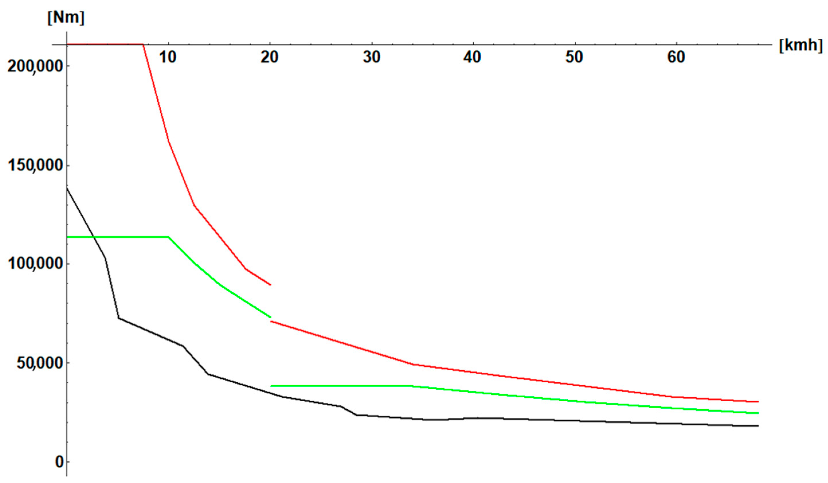
Figure 10 shows the torque of the SHEV compared to the torque of a traditional ICE-powered MBT.
The blue curve of torque at sprocket (Figure 10) is always above the black curve of a traditional ICE-powered MBT. This is not true for the continuous curve of torque at sprocket (green) of Figure 10. This is due to the fact the starting torque can be held only for a few seconds, both in the ICE-powered MBT and in the SHEV MBT. Another very important condition is given by the shift from the lower speed to the higher speed of the final drives. Certain continuity of torque should be kept avoiding shocks on the gearboxes, tracks, and motors. Figure 11 also shows that even in the worst conditions: Vehicle running and shifting at full torque (green line), the instantaneous torque (red line) will provide a smooth shifting at about 20 km/h.
The curves of Figure 10 and Figure 11 demonstrate that the MBT can operate with the SHEV transmission and motors. These motors will take the energy from the ICE generator. This unit will run independently, just keeping the microgrid electrical parameters within tolerances. Therefore, the amount of power installed is a choice of the designer, who can choose to fully exploit the torque capacity of the electric motors or to cut the maximum torque with a smaller and lighter ICE generator. The power requirements are shown in Figure 12 for continuous (green) and transient operations (red). A minimum power of 1500 HP is required to have a smooth gearshift at full throttle. The SHEV tank will outperform the traditional one in both off-road (below 20 km/h) and on-road conditions. The torque available is higher in most conditions, and gear shifting is nearly absent with smoother operations and less track and transmission fatigue.

3.4. Shev Reliability

Concerns about the dependability of HEVs have grown significantly because of recent statistical data from the automotive market. This paper will look at the architecture of a vehicle with a standard diesel IC engine, followed by parallel SHEVs. Initially, some assumed reliability numbers are used to introduce, and then the reliabilities of elements and total subsystem are analyzed. Naturally, it is important to acknowledge that consistent and supported results of these kinds of systems are required with some tests, such as experimental tests, modeling and simulation of the design. In our case, most of these data are taken from the automotive market. It is necessary to keep the basic or proven values of these kinds of subsystems. For the purposes of this discussion, when we talk about reliability, the probability that a component, subsystem, or system is functional which performs in a specific time period. In this period, there are no other changes in this system or a maintenance issue. As a result, reliability is linked to probability and time. Additionally, we define availability by considering a hypothetical system with a reliability of one. It will be referred to as “fully” available. Using the straightforward approach outlined below, system reliability regarding each subsystem of a SHEV can be examined. Take into consideration the various items shown in the first column of the table and assume that the reliability of each of those items is as shown in Table 4 [19].
Keep in mind that numerous constituent subsystems and components are used to construct each of the aforementioned items. However, a single cumulative reliability number can be used for each of the aforementioned items. Instead of delving into the motor’s individual components, one example is that an overall reliability of 0.99974 can be used. If the ICE power unit has a reliability rating of, say, 0.99974, there is a three in 10,000 chance that it will break down in 1000 h. It is true that as a system ages, reliability decreases. However, for the purposes of this discussion, it will be assumed constant. In the system described above, the only redundant system is the motor assembly on each sprocket, which survives a single motor failure. Two motors in parallel and one motor in serial arrangement, therefore, compose the system. Equation (12) shows that the three-motor system has approximately the same reliability as the single motor.
R motors = ( 1 ( 1 R ASS ) 2 ) R ASS = 0.9989
The overall SHEV reliability is calculated in Equation (13).
R = ICE ASS M ASS 2 G ear 2 HEV c P elect = 0.9929
Therefore, the power pack has seven probabilities of failure in 4500 h. This figure is unacceptable for an MBT, therefore, the TBO should be reduced. During the Vietnam War, the M113 power pack was replaced every 300 h. In our case, we would have had 0.5 failures in 300 h. By using two ICEs instead of one, the reliability would be 0.99959 or four failures in 4500 h. However, the diagnostic probability should be considered. The SHEV has an OBD system for every component. This software runs with the real-time controllers of the various subsystems. The early diagnosis probability is the probability of diagnosing a failure in time to repair the failing part before the failure occurs. These values are summarized in Table 5.
DR = DICE ASS DM ASS 2 DG ear 2 DHEV c DP elect = 0.9959
The probability of an early failure diagnosis DR is four in 4500 h (14). The SHEV is still not reliable enough for a TBO of 4500 h. Everything changes if two ICE subsystems are used in the SHEV, with one failure probability over 4500 h. This figure is acceptable. Therefore, it is convenient to use two ICE subsystems instead of one. The two subsystems may output half the power. In this case, a single ICE failure will reduce the MBT performance but not its safety.

3.5. Redundant Electronic Gearbox

A configuration of a dual-drive transmission is sketched in Figure 10. The two ICEs (Internal combustion Engine) are coupled with two “G” s (Generator) each. The cross-coupling of the ICEs with the sprockets due to the common microgrid makes it possible to energize each sprocket even with an ICE or two “M”s (Motors) inactive. In this way, the overall reliability scope is enhanced, giving the possibility to move the vehicle even with an engine inoperative. In addition, it is possible to use a single ICE as an APU (Auxiliary Power Unit) when the vehicle is stopped. The comparison of the MTU 883 engine with a smaller automotive-derived engine is summarized in Table 4 and Table 5. Engine volumes in Table 4 and Table 5 are misleading. In fact, for the Oral and the MTU engines, it is the volume without air boxes, exhaust, and turbochargers, while for the automotive engines is the overall volume with the automotive air filter that should be replaced for military use. The automotive/marine engines that are very inexpensive commercial units are less performing than the Oral engine, but are much lighter and more cost-effective than the MTU 883.

3.6. Example of Electric Dual Drive Powerpack

Imagine a modern MBT with a weight of 30 t. With a suitable ground pressure (below 0.77 daN/cm2), a 600 HP power pack is sufficient for an acceptable max speed (70 km/h), which is the practical limit for steel tracks. Rubber tracks are not usable on military vehicles due to on-field maintenance problems. Therefore, the solution from Figure 13 can be adopted. For the ICE, it is possible to choose the Alfa Romeo 2.2 JTD engine (Jet Turbo Diesel) that outputs 300 HP. For the electric motors/generators, a 37 kg unit will have a peak torque of about 800 Nm and a peak power of 200 kW@4000 rpm. The weight of each ICE will be 224 kg. Air filters, radiators, fans, FADECs for the engines, and the motors will add 50 kg. Each APU power pack will weigh approximately 290 kg. The two motors on the sprockets with the radiators and the drive units will weigh about 120 kg. Therefore, the total weight of the “power system” that is installed as three units (powerpack, left and right final drive) will be 820 kg, which is a fraction (23%) of the 3500 kg of a traditional system. The use of three electric motors for each sprocket must be considered. Following this approach, it is also possible to use two or more ICEs in parallel and to achieve the necessary reliability.

4. Discussion

The implementation of electric drives on modern armored vehicles is possible because of fully reversible, motor/generators. The best available now are the axial flux permanent magnet motor/generators. They obtain very high instantaneous torque at zero or low rpm. This fact is ideal for heavy vehicles. Modern electronics not only give the possibility to have reliable transmissions but also to avoid the installation of large batteries between motors and generators. This paper demonstrates that also for MBTs with weights that can range from 50 to 100, it is possible to replace the cumbersome automatic gearbox, the torque converter/multiplier, and the energy-recirculating steering unit with two sets of motor/generators that operate the right and the left final drive. The dual-drive steering system is operated by an electronic steering system. The SHE transmission is split into two parts. The “users” part includes the motors and their controllers. The generation part is composed of MGUs (Motor Generator Units). The MGUs operate like a power station on the national grid. In this case, they keep the electric parameters of the vehicle micro-grid within tolerances. This paper introduces the preliminary design of electronic transmission for a big MBT. The system is shown in Figure 8 and Figure 9a,b. The available and the required torque are shown in Figure 10 and Figure 11. It was necessary to implement a two-shift robotized clutchless gearbox in the final drive because the axial flux motors are limited in maximum speed. The first speed will work in traditional off-road operation up to 20 km/h, while the second speed will reach the required 68 km/h. A redundant system allows the failure of one motor per side without affecting the capability to operate and return home. The MGU is the problem with its huge power requirement of at least 1500 HP for a full-throttle shift from the first to the second gear. Again, the generators are not a problem. The system is split into three generators in parallel. With two generators the MBT would operate normally. With one generator operational, it can still limp home. The problem is the ICE. In Figure 8, the large Caterpillar “Cat C32 ACERT Marine Propulsion Engine (2000 HP @ 2300 rpm)”. This excellent engine is too large and too heavy for an MBT. Theoretically, it is possible to reduce the requirement to 1800 HP and use an MTU 883 ICE. Unfortunately, the requirement to have two MGUs on the vehicle to achieve the required reliability of one failure over 100,000 in 4500 h imposes the possibility of using two MGUs. It is difficult to find on the market modern, common rail diesels of 1000 HP each. It would be easier to find two 700 HP common rail diesel engines, but the customer has to accept that. In a few cases, the maximum torque is not the maximum available from the electric motors (see Figure 12). In any case, the performance of the hybrid vehicle would be much better than a traditionally powered MBT (see Figure 10) with higher torque, only one shift, and no power recirculation necessary when steering. This would happen even with a single 1000 HP ICE (see Figure 10 and Figure 12). In order to have a realistic figure of the total weight of the powerpack for a SHEV, a 600 HP system was considered. This power pack would be ideal for a modern 30 t MBT that will rely on an active armor system for protection like the Rafael Trophy. In this case, it is possible to install two 300 HP MGUs that are readily available from the automotive market. The use of three electric motors per sprocket and one generator per ICE would achieve the required reliability. In this case, most of the subsystems can be commercial apart from the PMU (Power Management Unit) and the PDDU (Power Dual Drive Unit) that should be integrated into the electronic vehicle control system. This 600 HP power system will save more than 70% of the mass of a traditional transmission. This is due to the fixed, high rotational speed of the ICE and the extremely high torque-to-mass ratio of the axial flow electric motor. The last generation, common rail, automotive-derived ICE has the crankcase and the head made of aluminum alloy. Other important weight savings are obtained by using automotive-derived, polymeric, high-efficiency fans, and air conveyors.

5. Results

This paper demonstrated that it is possible to use a serial electric hybrid power system for MBT exceeding 50 tons. The torque available in any condition is at least twice the one of a traditional power pack transmission. The use of batteries in armored vehicles is still troublesome. Therefore, to achieve the full torque rate available, a more powerful ICE is necessary. Especially for heavy armored vehicles in the class of more than 50 tons, the availability of off-the-shelf engines is limited, and the marine units that are available are too heavy and too large to be used in armored vehicles. A few new engines are available, like the Oral CR diesel, but they are still prototypes. On the contrary, in the 30 ton/600 HP class many automotive solutions are available. It is true that when using the armored vehicle with the same acceleration and velocity pattern, the fuel consumption is nearly halved. Unfortunately, the new SHEV is much more performing with high torque and high acceleration, and the mobility is greatly improved. Therefore, if the SHEV is used fully, it will outperform traditional vehicles, at least doubling the deceleration values. Unfortunately, even if the SHEV is more efficient, more fuel will still be needed due to the better mobility. Therefore, in the end, at least in combat conditions, more fuel will be necessary. The maintenance is easier to perform, and the logistic is facilitated by the OBD system.

6. Conclusions

This paper demonstrated that it is possible and convenient to use a serial hybrid arrangement for the transmission on many armored vehicles up to the very large Main Battle Tanks. The advantages are in mobility due to higher acceleration and smoothness. The overall reliability of the propulsion system is improved. In fact, redundancy and early diagnosis reduce the possibility of a power pack failure. The convenience of using a battery is doubtful due to the fire risks and the weight, especially in larger vehicles. The preliminary design of a hybrid electric transmission for 1500 HP, 50+ tons MBT demonstrates that this system is feasible and outperforms traditional systems. The availability of a micro power grid in the vehicle simplifies the installation of subsystems in the vehicle, reducing installation and maintenance costs. Finally, with the same speed-acceleration pattern, significant fuel savings are possible due to the fixed-point functioning of the internal combustion engine.

Author Contributions

Conceptualization, L.P. and E.P.; methodology, M.T.; validation, M.S., C.L.-C. and M.T.; formal analysis, L.P.; investigation, M.T.; resources, L.P.; data curation, C.L.-C.; writing—original draft preparation, C.L.-C.; writing—review and editing, C.L.-C.; visualization, M.S.; supervision, E.P.; project administration, L.P.; funding acquisition, E.P. All authors have read and agreed to the published version of the manuscript.

Funding

This research received no external funding.

Data Availability Statement

Not applicable.

Conflicts of Interest

The authors declare no conflict of interest.

References

  1. Board on Army Research and Development; Division on Engineering and Physical Sciences; National Academies of Sciences; Medicine, E. Powering the US Army of the Future; The National Academies Press: Washington, DC, USA, 2021; p. 163. ISBN 978-0-309-25803-6. [Google Scholar]
  2. Rangarajan, S.S.; Sunddararaj, S.P.; Sudhakar, A.; Shiva, C.K.; Subramaniam, U.; Collins, E.R.; Senjyu, T. Lithium-Ion Batteries—The Crux of Electric Vehicles with Opportunities and Challenges. Clean Technol. 2022, 4, 908–930. [Google Scholar] [CrossRef]
  3. Houache, M.S.E.; Yim, C.H.; Karkar, Z.; Abu-Lebdeh, Y. On the Current and Future Outlook of Battery Chemistries for Electric Vehicles—Mini Review. Batteries 2022, 8, 70. [Google Scholar] [CrossRef]
  4. Piancastelli, L.; Sali, M.; Leon-Cardenas, C. Basic Considerations and Conceptual Design of a VSTOL Vehicle for Urban Transportation. Drones 2022, 6, 102. [Google Scholar] [CrossRef]
  5. Chen, Y.; Kang, Y.; Zhao, Y.; Wang, L.; Liu, J.; Li, Y.; Liang, Z.; He, X.; Li, X.; Tavajohi, N.; et al. A Review of Lithium-Ion Battery Safety Concerns: The Issues, Strategies, and Testing Standards. J. Energy Chem. 2021, 59, 83–99. [Google Scholar] [CrossRef]
  6. BU-304a: Safety Concerns with Li-Ion. Available online: https://batteryuniversity.com/article/bu-304a-safety-concerns-with-li-ion#:~:text=These%20batteries%20made%20available%20for,in%20clothing%20and%20while%20traveling (accessed on 3 December 2022).
  7. Klink, J.; Hebenbrock, A.; Grabow, J.; Orazov, N.; Nylén, U.; Benger, R.; Beck, H.-P. Comparison of Model-Based and Sensor-Based Detection of Thermal Runaway in Li-Ion Battery Modules for Automotive Application. Batteries 2022, 8, 34. [Google Scholar] [CrossRef]
  8. Stephens, D.; Shawcross, P.; Stout, G.; Sullivan, E.; Saunders, J.; Risser, S.; Sayre, J. Lithium-Ion Battery Safety Issues for Electric and Plug-in Hybrid Vehicles; Chapter 2; National Highway Traffic Safety Administration: Washington, DC, USA, 2017; Volume 10, p. 7. [Google Scholar]
  9. Network, A.S. Aviation Safety Network Report. Available online: https://aviation-safety.net/database/ (accessed on 14 December 2022).
  10. Sundén, B. Chapter 6—Thermal Management of Batteries. In Sunden Batteries and Fuel Cells; Ed. Academic Press: Cambridge, MA, USA, 2019; pp. 93–110. ISBN 978-0-12-816950-6. [Google Scholar]
  11. Hu, X.; Zheng, Y.; Howey, D.A.; Perez, H.; Foley, A.; Pecht, M. Battery Warm-up Methodologies at Subzero Temperatures for Automotive Applications: Recent Advances and Perspectives. Prog. Energy Combust. Sci. 2020, 77, 100806. [Google Scholar] [CrossRef]
  12. Rinaldini, C.A.; Allesina, G.; Pedrazzi, S.; Mattarelli, E.; Savioli, T.; Morselli, N.; Puglia, M.; Tartarini, P. Experimental Investigation on a Common Rail Diesel Engine Partially Fuelled by Syngas. Energy Convers. Manag. 2017, 138, 526–537. [Google Scholar] [CrossRef]
  13. Jääskeläinen, H.; Khair, M.K. Common Rail Fuel Injection. DieselNet 654 Technol. Guid. 2015. Available online: https://dieselnet.com/tech/diesel_fi_common-rail.php (accessed on 10 December 2022).
  14. Piancastelli, L.; Frizziero, L.; Donnici, G. The Common-Rail Fuel Injection Technique in Turbocharged Di-Diesel-Engines for Aircraft Applictions. ARPN J. Eng. Appl. Sci. 2014, 9, 2493–2499. [Google Scholar]
  15. Khalil, G.; Danielson, E.; Barshaw, E.; Chait, M. Power Supply and Integration in Future Combat Vehicles. In Proceedings of the RTO AVT Symposium on “Functional and Mechanical Integration of Weapons and Landand Air Vehicles”, Williamsburg, VA, USA, 7–9 June 2004; pp. 39-1–39-12. [Google Scholar]
  16. Adams, C.E.; Satynarayana, K. Nato Foreign Diesel Comparative Test Program GM-MVO/MT883 EgNE Evaluation; Report No. 13461; US Army Tank Automotive Command: Warren MI, USA, 1991. [Google Scholar]
  17. Nikhil Kumar, C.; Kumar, S. Full Authority Digital Engine Control (FADEC). Int. J. Emerg. Trends Sci. Technol. 2015, 2, 3298–3302. [Google Scholar]
  18. Mi, C.; Masrur, M.A.; Wenzhong Gao, D.W. Hybrid Electricehicles Principles and Applications with Practical Perspectives; John Wiley & Sons, Ltd.: Chichester, UK, 2011; ISBN 978-0-470-74773-5. [Google Scholar]
  19. Piancastelli, L.; Frizziero, L.; Donnici, G. Turbomatching of Small Aircraft Diesel Common Rail Engines Derived from the Automotive Field. ARPN J. Eng. Appl. Sci. 2015, 10, 172–178. [Google Scholar]
Figure 1. Available power packs for armored vehicles. The 10 to 18 tons vehicles use power packs from 1100 to 2500 kg. The 25 to 30 tons vehicles need 3.5 to 4.5 tons for the power pack. While for heavier vehicles, 6.5 to 8.5 tons are required.
Energies 16 02605 g001
Figure 2. Power pack replacement of an MBT. The red line includes the power pack. It is probably an MTU Powerpack and a Leopard II MBT.
Energies 16 02605 g002
Figure 3. Available power vs. speed for a typical, traditional MBT power pack [16].
Energies 16 02605 g003
Figure 4. Available torque vs. speed for a typical, traditional MBT power pack [16].
Energies 16 02605 g004
Figure 5. Brake Specific Fuel Consumption of a traditional MBT Engine [17].
Energies 16 02605 g005
Figure 6. Brake Specific Fuel Consumption of a CR (Common Rail) Engine.
Energies 16 02605 g006
Figure 7. Typical torque pattern vs. rpm of a modern axial-flux electric motor. The red line is instantaneous torque (a few seconds). The green line is continuous torque. The black line is a torque level that can be output for minutes.
Energies 16 02605 g007
Figure 8. SHEV power pack and transmission with dual drive for a large MBT; (1) engine; (2) generator(s); (3) motors of right sprocket; (4) motors of left sprocket; (5) final reduction and sprocket right side; (6) final reduction and sprocket left side.
Energies 16 02605 g008
Figure 9. (a). Size of the dual drive power pack with a single diesel engine for a large MBT (Top View). (b) Size of the dual drive power pack with a single diesel engine for a large MBT (Side View).
Energies 16 02605 g009
Figure 10. SHEV torque available at sprocket (blue curve, minutes) compared with a traditional ICE- MBT (black curve).
Energies 16 02605 g010
Figure 11. SHEV continuous torque available at sprocket compared with a traditional ICE-MBT (black curve). The red line is the instantaneous torque from the SHEV motors.
Energies 16 02605 g011
Figure 12. SHEV continuous power required at sprocket continuously (green curve). The red line is the instantaneous power from the SHEV motors.
Energies 16 02605 g012
Figure 13. Dual Drive, dual engine configuration.
Energies 16 02605 g013
Table 1. Performance of an Automotive Traction Motor.
ParameterContinuousInstantaneousDifference [%]
Torque [Nm]90045050
Power [HP]18715322
Speed [rpm]3500400014
Volume [lt]10--
Mass [kg]39--
Table 2. Comparison of several MBT Engines.
ParameterT55T72/T90MTU 883 GMOral
Vol.
[m3]
1.191.181.471.17
Mass
[kg]
102010201909426
HP700100015001400
HP/kg0.680.980.783.28
HP/m358584410201192
Disp [lt]38.8838.8827.3610
gr/HPh182156150129
Table 3. % Comparison of several MBT Engines. The reference engine is the MTU 883 GM.
ParameterT55T72/T90MTU 883 GMOral
Vol.
[%]
808010079
Mass
[%]
535310023
HP [%]466710093
HP/kg [%]87124100418
HP/m3
[%]
57.783100116
Disp. [%]14214210036
gr/HPh
[%]
14210410086
Table 4. Reliability of SHEV subsystems.
SubsystemReliability in 4500 hSymbol
ICE + ECU + Fuel system + Alternator0.9997ICEASS
Motor + Controller0.99989MASS
Gearbox0.99995Gear
HEV control0.99999HEVc
Power Electronics0.99992Pelect
Table 5. Probability of early diagnosis in subsystems.
SubsystemDiagnostic Reliability in 4500 hSymbol
ICE + ECU + Fuel system + Alternator0.9997DICEASS
Motor + Controller1DMASS
Gearbox0.99995DGear
HEV control0.99999DHEVc
Power Electronics1DPelect
Disclaimer/Publisher’s Note: The statements, opinions and data contained in all publications are solely those of the individual author(s) and contributor(s) and not of MDPI and/or the editor(s). MDPI and/or the editor(s) disclaim responsibility for any injury to people or property resulting from any ideas, methods, instructions or products referred to in the content.

