Abstract
To realize a hydrogen economy, many studies are being conducted regarding the development and analysis of hydrogen carriers. Recently, formic acid has been receiving attention as a potential hydrogen carrier due to its high volumetric energy density and relatively safe characteristics. However, hydrogen refueling systems using formic acid are very different from conventional hydrogen refueling stations, and quantitative risks assessments need to be conducted to verify their safe usage. In this study, a comparative safety analysis of a formic acid hydrogen refueling station (FAHRS) and a gaseous hydrogen refueling station (GHRS) was conducted. Since there is no FAHRS under operation, a process simulation model was developed and integrated with quantitative risk assessment techniques to perform safety analysis. Results of the analysis show that the FAHRS poses less risk than the GHRS, where the vapor cloud explosion occurring in the buffer tank is of greatest consequence. A GHRS poses a greater risk than an FAHRS due to the high pressure required to store hydrogen in the tube trailer. The mild operating conditions required for storage and dehydrogenation of formic acid contribute to the low risk values of an FAHRS. For risk scenarios exceeding the risk limit, risk mitigation measures were applied to design a safe process for GHRS. The results show that the installation of active safety systems for the GHRS allow the system to operate within acceptable safety regions.
1. Introduction
Due to the imminent climate crisis, researchers around the world are striving to find an alternate energy source to fossil fuels. Among the various options, hydrogen is considered a probable candidate, owing to its high energy density and green nature. While currently, hydrogen is mainly produced by methane reforming, integration with renewable electricity can deliver hydrogen production with minimal carbon emissions. If this so-called “green hydrogen” can be widely distributed, hydrogen can function as an energy source for industry, households, and automobiles, supporting a carbon-free society, which is often referred to as the hydrogen economy [1].
However, many obstacles stand in the way of realizing a hydrogen economy. The largest obstacle is the difficulty of efficient storage and transportation, which stems from the low volumetric energy density and small molecular size of hydrogen [2]. Since hydrogen is the most lightweight element, high-pressure storage is necessary to deliver the same amount of energy compared to conventional fuel. For instance, a fuel cell electric vehicle (FCEV) requires 7–8 kg of hydrogen to provide the same amount of distance as a gasoline vehicle, which requires storage at 700–900 bar. Distributing hydrogen to the hydrogen refueling stations (HRSs) is also difficult, considering the high pressure or low temperature required to deliver hydrogen in gaseous or liquefied state. These harsh operating conditions naturally lead to safety problems, which represent a problem when considering the realization of the hydrogen economy.
To overcome these obstacles, various hydrogen delivery options are being considered to find the most energy-efficient pathway. Other than gaseous or liquefied hydrogen transport, hydrogen carriers, which are capable of providing hydrogen at the usage site while containing it under mild conditions during transportation and storage, are being considered [3,4,5,6,7,8]. Candidates for hydrogen carriers include toluene, methylcyclohexane, ammonia, methanol, formic acid, etc. Carbon-ring structures such as toluene and methylcyclohexane are considered promising hydrogen carrier candidates because they retain liquid states after dehydrogenation and can be recycled back to their production site for further usage [9]. However, more research needs to be conducted in terms of enhancing their energy efficiency since they require harsh operating conditions for dehydrogenation.
Recently, a lot of attention has been given to chemicals such as ammonia, methanol, and formic acid as hydrogen carrier candidates. With the recent interest in the development of feasible carbon mitigation options, methanol and formic acid can be integrated in the carbon utilization processes to provide a means of fixing CO2 from the atmosphere. In addition, there is growing interest in integrating green hydrogen production with ammonia production to mitigate the large carbon footprint of the conventional Haber–Bosch process [7,10,11,12,13]. Furthermore, because these chemicals already have a market, the existing infrastructure can be used for their distribution, resulting in fewer hurdles for commercialization. Formic acid has recently attracted considerable attention because it exists as a liquid at standard temperature and pressure, has relatively low toxicity, and retains high volumetric energy density compared to other candidates [14]. While many studies have been conducted on the development of processes and economic and environmental assessments of CO2-utilized formic acid production, studies on the use of formic acid as a hydrogen carrier are still at an early stage. A few studies have presented results on the development of processes incorporating formic acid as a hydrogen carrier. Kim et al. [7] provided process models and technoeconomic and environmental evaluation results of a hydrogen distribution system using formic acid as the carrier [7]. They considered a hydrogen distribution cycle including the production of formic acid via various pathways of CO2 hydrogenation, transportation of formic acid to an HRS, and recapture and transport of CO2 back to the site of formic acid production. The results of their study include a process model design based on state-of-the-art developments in formic acid production and dehydrogenation and show that electrochemically produced formic acid is an economically viable option for hydrogen distribution. A study by van Putten et al. demonstrated a prototype fuel cell bus empowered by hydrogen obtained via formic acid dehydrogenation [10]. The authors presented a realized fuel cell bus obtaining hydrogen from formic acid using a homogeneous catalyst system to effectively dehydrogenate formic acid. They also integrated a methanation reactor to minimize CO production, allowing stable power generation from the fuel cell. The results of these studies show that formic acid can be a viable hydrogen carrier, considering its technoeconomic and environmental feasibility.
However, for commercial operation of a formic acid hydrogen refueling station (FAHRS), a thorough safety assessment of the system is required. A hydrogen refueling station (HRS) is potentially subject to hazardous situations, and such stations have experienced large accidents resulting in individual and social consequences [15,16,17,18]. Due to the high-pressure requirements of the storage system and high specific energy of hydrogen, leakage or rupture of could lead to catastrophic accidents. While formic acid can be deemed an effective hydrogen carrier in terms of economic and environmental viability, a thorough risk assessment of FAHRSs is essential to allow for further implementation of such systems. Intuitively, an FAHRS could be advantageous compared to a gaseous HRS (GHRS), considering the fact that formic acid dehydrogenation can occur under mild conditions, owing to the recent developments made in high performance heterogeneous catalysts [13,19]. However, a comprehensive analysis of the safety of FAHRS is required, since formic acid has different characteristics than those of conventional gas fueling station or HRS. A few studies have involved safety analyses of hydrogen refueling stations [15,17,18,20,21], and some studies have considered safety analysis of hydrogen-carrier-based refueling stations, such as the study by Suzuki et al. [22], in which methylcyclohexane was considered as the hydrogen carrier, and the study by Bae et al. [23], in which risk assessment of an ammonia-based hydrogen refueling station was conducted. However, no studies are available for the systematic safety analysis of an FAHRS.
In this study, a systematic safety analysis of a FAHRS is conducted. Since a commercialized FAHRS is yet to be realized, rigorous process simulation using Aspen Plus was used in integration with quantitative risk assessment to analyze a FAHRS system. Aspen Plus is a process simulation software capable of simulating thermodynamic phenomena [24] and can be used in process assessment studies by providing material and energy balances [7,25]. The safety evaluation results were compared with those of gaseous hydrogen refueling stations (GHRSs), which are the dominantly used form of hydrogen refueling stations. Two simulation models—one for the FAHRS system and another for the GHRS system—were designed; then, quantitative risk assessment (QRA) was conducted using hazard identification and risk assessment. In addition, risk mitigation measures to allow safer operation of the FAHRS and GHRS were implemented.
2. Process Design and Simulation
Both the FAHRS and GHRS were designed with a capacity of 850 kgH2/d, following the assumptions made by Wulf et al. [4,5] corresponding to a formic acid flowrate of 19,407 kg/d. The tank reservoirs were designed with a capacity that allows for fill-up of the tank three times a year for both formic acid and gaseous H2.
2.1. FAHRS System
The FAHRS system was modeled based on the state-of-the-art formic acid dehydrogenation reactor reported in the literature. A schematic representation of the process flow diagram (PFD) considered for the two HRS systems is provided in Figure 1. The GHRS model is based on the process design provided in the work by Yoo et al. [20]
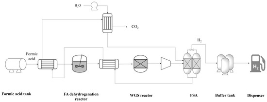
Figure 1.
PFD of the FAHRS system. Heat exchangers are used to maximize the energy efficiency.
The FAHRS design is based on the catalyst suggested by Hong et al. [19], and the process design is based on the dehydrogenation system design suggested by Kim et al. [7]. Hong et al. [19] developed the PdAu nanoparticle catalyst supported on MSC-30 carbon, which is a heterogeneous catalyst showing near 100% selectivity for FA decomposition to H2 under mild conditions of 60 °C. Kim et al. [7] showed that an FA dehydrogenation system incorporating the PdAu nanoparticle catalyst design allows for economic hydrogen distribution, making it a feasible option for FAHRS. The PFD of the FAHRS includes the heat integration of streams to maximize the energy efficiency, as shown in Figure 1. The dehydrogenation reactor is designed to operate at 60 °C and 1 bar. While the formic acid is easily decomposed using the proposed catalyst, two reactions are available within the dehydrogenation reactor. The main reaction is the deformation of formic acid to CO2 and H2, with a selectivity of 95%. The side reaction is the deformation of formic acid to CO and H2O, which is a common side reaction of formic acid since both reactions occur spontaneously under standard operating conditions [14]. Due to the small portion of CO produced by the dehydrogenation reactor, a water–gas shift (WGS) reactor is installed to eliminate the CO and to maximize H2 production. Since the fuel cell system is sensitive to CO concentrations, a typical fuel cell limits CO to less than 10 ppm for stable operation [10]. Thus, the WGS reactor acts as a safety measure for stable operation of the FAHRS system. The WGS reactor is designed to be operational at 250 °C and 1 bar. Downstream of the WGS reactor, a pressure swing adsorption (PSA) unit is added to separate CO2 from H2. The PSA unit was designed based on the work by Zhu et al. [26]; the PSA unit includes WGS catalysts and zeolites to maximize H2 production. The PSA unit operates at elevated temperatures of 400 °C and 30 bar. The H2 buffer tank was designed based on the operating conditions provided by Wulf et al. [4,5], which are 40 °C and 870 bar.
2.2. GHRS System
As for the GHRS model, the process scheme and operating conditions provided in the work by Yoo et al. [20] were used. A schematic representation of the PFD of the GHRS is provided in Figure 2. Comparing Figure 1 and Figure 2, the FAHRS and GHRS share the same operating units downstream of the dehydrogenation step, namely the H2 buffer tank and the dispenser. Details of the operating conditions of the relevant process units with respect to safety analysis are provided in Table 1 and Table 2 for the FAHRS and the GHRS, respectively.
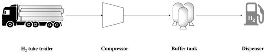
Figure 2.
Schematic PFD of the GHRS system.

Table 1.
Accident scenarios of the FAHRS system. Scenarios are defined for the individual units, and the operating conditions of the units and the corresponding initial frequency values obtained from literature are provided.
Table 2.
Accident scenarios of the GHRS system. Scenarios are defined for the individual units, and the operating conditions of the units and the corresponding initial frequency values obtained from literature are provided.
3. Methodology
In this study, a systematic QRA was conducted for both the FAHRS and GHRS to comparatively assess their safety. An HRS located in an urban area of South Korea was selected, as shown in Figure 3, based on the information provided by Yoo et al. [20] and Bae et al. [23] The HRS retains a size of 65 m × 100 m, and residences, and expressways and large populations are located nearby, making safety assessment and related mitigation strategies essential. Regarding the selected HRS, QRA was conducted for the FAHRS and GHRS cases based on the following steps. While the specific locations of the units are required to rigorously evaluate the risks of each failure, it is not possible to identify the locations of the FAHRS case, since no commercial case is available. Herein, it is assumed that all of the units are located at the same site to maximize the risk evaluation results. Since the purpose of this study is to provide a fair comparison of FAHRS with respect to the commercialized GHRS, the results obtained based on this assumption do not violate this purpose.
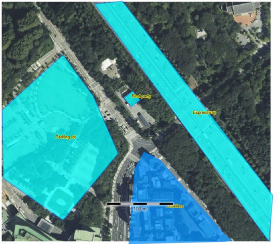
Figure 3.
Satellite image of the HRS considered in this study. An expressway exists east of the HRS, and a residential area exists to the south of the HRS.
3.1. Hazard Identification (HAZID)
Hazard identification (HAZID) is the process of identifying all of the hazards that could occur with respect to the process model. The hazardous materials considered in this study are formic acid and H2. Formic acid is flammable in its liquid and vapor states. It retains a flash point of 50 °C and has a low explosion limit of 10 vol%. Compared to formic acid, H2 has an even lower explosive limit of 4 vol%, with a high maximum limit of 75 vol%. Since toxicity is not an issue for formic acid and H2, only the flammability is considered for both FAHRS and GHRS systems.
3.2. Scenario Definition
To allow for efficient risk assessment of the FAHRS and GHRS cases, scenarios were defined regarding the most relevant process units. Considering the most vulnerable operating units for both FAHRS and GHRS provides a fair comparison of the two systems.
Regarding the PFD of FAHRS provided in Figure 1, the formic acid tank, dehydrogenation reactor, WGS reactor, PSA unit, H2 buffer tank, and dispenser were considered for risk analysis. While the intermittent units connecting these units also retain a certain amount of chemicals, the tanks and reactor are much larger in volume, posing a higher risk compared to other units. The harsh operating conditions of the PSA unit, H2 buffer tank, and the dispenser also significantly outweigh the potential risks of units such as the heat exchangers and chillers. As for the GHRS system, the H2 tube tank, buffer tank, and the dispenser were considered for risk analysis. Details of the potential accident scenarios, and the related operating conditions and inventories are provided in Table 2.
3.3. Risk Analysis
3.3.1. Frequency Analysis
After the potential accidents were defined for both FAHRS and GHRS systems, the probability of occurrence for each of the accident scenarios were analyzed through event tree analysis (ETA). The overall list of considered events is shown in Figure 4.
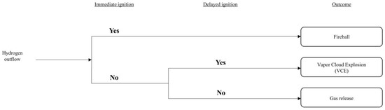
Figure 4.
Event tree analysis (ETA) results.
Based on the analysis provided by the ETA and considering the parameters obtained from the literature, such as the purple book [28], Yoo et al. [20], and Bae et al. [23], frequency analyses for both the FAHRS and GHRS systems were conducted. Results of the frequency analyses are provided in Table 3 and Table 4.
Table 3.
Frequency analysis results for the FAHRS system.
Table 4.
Frequency analysis results for the GHRS system.
Frequency analysis results for the FAHRS system are provided in Table 3. It is evident that the risk frequency regarding the PSA unit and the H2 buffer tank is the highest, considering the high operating pressures of the two units.
Frequency analysis results for the GHRS system are provided in Table 4. Compared to the FAHRS system, the tube trailer and H2 buffer tank units show the same probability of occurrence.
3.3.2. Consequence Analysis
Consequence analysis identifies the lethal effects of accidents by modeling the damage at a given exposure. Two parameters are used to indicate the lethal effects of a certain accident: the probability of death of an individual upon exposure (PE) and the fraction of the population dying (FE). When evaluating PE, the individual is assumed to be outdoors and unprotected. FE is evaluated at a certain location for the population dying both indoors and outdoors. For each of the accident scenarios, the PE is used to calculate the individual risk contours, and the FE is used to calculate the societal risk.
The probability of death (P) for a certain accident is calculated using a corresponding probit (Pr), as shown in Equation (1) [28].
The individual probit functions for each of the accidents are described below. Exposure to fire and explosion are considered, as they are the main incidents of concern in this study.
Regarding exposure to fire, which includes jet fire, pool fire, and fireball scenarios, the probit function is expressed as [28]:
where Q is the heat radiation (W/m2), and t is the exposure time (s).
For the explosion scenarios, lung hemorrhage resulting from the peak overpressure is the main cause of death. While other probit equations exist considering the overpressure effects induced by explosion, such as structural damage and glass breakage, only the lethal damage incurred due to lung hemorrhage is considered in this study. The probit equation for death by lung hemorrhage is given in Equation (4) [29],
where Pp represents the peak overpressure induced by the explosion (N/m2).
3.3.3. Individual Risk and Societal Risk
Using the frequency and consequence calculations provided in the previous sections, the individual risk (IR) and the societal risk (SR) were evaluated to quantitatively assess the risk of an accident scenario. The individual risk is calculated using the equations presented below:
where IRx,y denotes the summation of IR of fatality at a designated location (x,y) regarding the N number of accident scenarios (i). The IR for each of the scenarios (i) is evaluated by multiplying the frequency of the scenario (fi) by the probability of scenario i leading to fatality (pfi).
4. Results and Discussion
4.1. Consequence Analysis
Two commercial software programs developed by Gexcon Netherlands, EFFECTS v12 and RISKCURVES v12, were used for consequence analysis. EFFECTS v12 calculates the physical effects of hazardous material leakage, and RISKCURVES v12 quantifies individual and societal risks. Both software programs are used worldwide as reference safety analysis tools [30,31] and have been incorporated in various safety studies [32,33,34]. For each of the scenarios shown in Table 1 and Table 2, the consequences were evaluated. Since many scenarios exist for the FAHRS and GHRS systems, the consequence analysis results for the scenarios retaining the largest range of impact were considered.
Figure 5 shows the consequence results of the worst-case scenarios for FAHRS and GHRS. The overpressure contours of the VCE scenario occurring due to the catastrophic rupture of the H2 buffer tank are shown in Figure 5a. Contours are shown for three different overpressures, i.e., 206.8, 137.9, and 20.68 mbar, which correspond to the high, medium, and low overpressure levels. As seen in Figure 6a, the area affected by the overpressure level of 137.9 mbar is 34.4 m. While the affected area for the low overpressure level extends to the nearby expressway and the residence area, the medium and high overpressure level effects are limited to the refueling station. The overpressure contours for the H2 tube trailer-VCE scenario are provided in Figure 5b. As seen in Figure 6b, the diameter of the contour for the 137.9 mbar overpressure level is 142.7 m for the GHRS case, which covers more than 16 times the area affected by the FAHRS case. Even the high overpressure level of 206.8 mbar affects the nearby expressway and parking lot, posing a greater risk compared to the FAHRS.
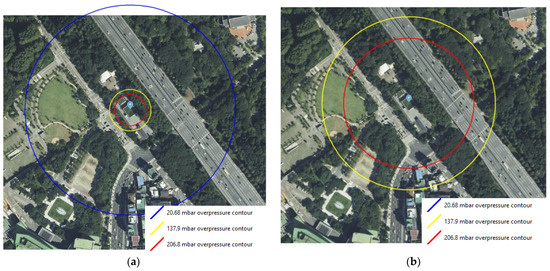
Figure 5.
The overpressure contours for the (a) VCE of FAHRS due to the rupture of the H2 buffer tank and (b) the VCE of GHRS due to the rupture of the H2 tube trailer. The 20.68 mbar contour for the GHRS case extends beyond the boundary of the considered area and is not depicted in the figure.
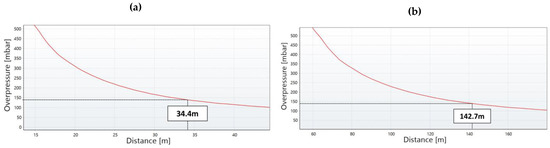
Figure 6.
The change in overpressure with respect to distance for (a) the FAHRS VCE scenario due to the rupture of the H2 buffer tank and (b) the GHRS VCE scenario due to the rupture of the H2 tube trailer. The affected distance for the overpressure level of 137.9 mbar (yellow contour in Figure 5) is shown for both cases.
4.2. Risk Analysis
The risk assessment results of both the FAHRS and GHRS cases were analyzed. The IR and SR of the two systems were analyzed using the commercial risk analysis software RISKCURVES v12. The IR contour and the plot of the frequency of events that causes at least N fatalities (F-N curve) are presented in Figure 7 for the FAHRS system and in Figure 8 for the GHRS system. The overall fatality range for the FAHRS system is relatively small compared to that of the GHRS system (Figure 7a), showing individual risk contours affecting only the region near the HRS. As seen in Figure 7b, the societal risk for the FAHRS does not exceed the safety limit, showing that it can be operated safely without additional risk mitigation measures. The actual risk values for each risk scenario of the FAHRS system and their relative contributions are provided in Table 5. For the FAHRS system, the gas fireball scenario from the H2 buffer tank represents the largest risk, retaining over 45% of the risk assessment results of the FAHRS system. The VCE scenarios of the H2 buffer tank and the PSA unit account for 36.2% and 17.9% of the total risk assessment results, respectively. While the PSA unit retains potential risks, quantitative results show that careful maintenance of the buffer tank is essential when considering the implementation of FAHRS.
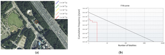
Figure 7.
Risk assessment results for the FAHRS system. (a) The risk analysis results and (b) the F-N curve.
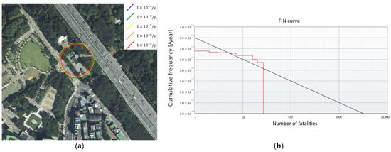
Figure 8.
Risk assessment results for the GHRS system. (a) The risk analysis results and (b) the F-N curve.
Table 5.
The societal risk values with respect to the scenarios for the FAHRS system.
For the GHRS, the individual risk contours are larger than for the FAHRS system, affecting the nearby parking lot (Figure 8a). As seen in Figure 8b, the F-N curve exceeds the upper limit for safe operation, indicating that additional safety mitigation is required. As opposed to the FAHRS case, the accident scenarios regarding tube trailers comprise more than 86% of the risk asserted by the GHRS system. The risk values of the buffer tank only contribute to 13% of the total risk. This is mainly due to the large amounts of hydrogen included within the tube trailer compared to the continuously operating buffer tank. Quantitatively, the risk value of the GHRS is shown to be ten times the risk value of the FAHRS. This shows that due to the difference in the hydrogen storage method, the FAHRS system poses much smaller risks compared to the GHRS system.
4.3. Risk Mitigation
Since the SR result of GHRS shown in Figure 8b indicates that the GHRS system exceeds the safety limit, mitigation measures must be applied for safe operation of the HRS. Among the various options available for risk mitigation, it is assumed that active safety systems are implemented, following the results of previous studies [20]. Active safety systems involve the installation of safety measurement systems capable of early detection and prevention of safety hazards. In this study, the installation of three safety barrier systems was considered: hydrogen detection sensors, detachable couplings, and emergency shutdown buttons. Implementation of these safety barrier systems mitigates the frequency of hazards by 1/10 each, reducing the occurrence of risks by a factor of . The results of applying the safety barrier systems are provided in Table 6. The resulting F-N curve obtained by applying the safety barrier systems for the GHRS is shown in Figure 9. While the GHRS retains much higher risks compared to the FAHRS, safe operation is possible with the aid of additional safety systems. Thus, when considering the implementation of an HRS, additional factors such as the economic potential and environmental effects must be considered in combination.
Table 6.
The risk values before and after applying safety mitigation measures with respect to the scenarios for the GHRS system.
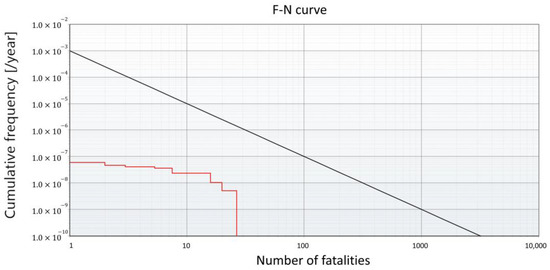
Figure 9.
F-N curve of the GHRS system after applying the active safety systems.
5. Conclusions
This study presents the safety assessment results for a FAHRS system in comparison with a commercialized GHRS system. By integrating a rigorous process model with systematic QRA, the potential risks of FAHRS and GHRS operation were thoroughly analyzed. The results show that, considering the various scenarios for the FAHRS and GHRS, including a fireball and VCE of the H2 buffer tank and the tube trailer, FAHRS retains less risk compared to GHRS. Since the operating conditions of formic acid storage and dehydrogenation are mild compared to gaseous hydrogen treatment, process units containing formic acid pose minimal risks considering the whole HRS. Thus, the largest risk factor of the FAHRS is the H2 buffer tank, but due to its small volume compared to the tube trailer of the GHRS, the consequences of implementing an FAHRS are minimal. The F-N curves show that while the FAHRS is safely operable without additional risk mitigation equipment, the GHRS requires the implementation of active safety systems to reduce the overall risk. Application of three different active safety systems allows the GHRS to be operable under safe conditions.
Author Contributions
Conceptualization, C.K. and Y.L.; methodology, Y.L.; software, Y.L.; writing—original draft preparation, C.K.; writing—review and editing, K.K. All authors have read and agreed to the published version of the manuscript.
Funding
This research was funded by the National Research Foundation of Korea (NRF-2022M3C1A309205), and by the C1 Gas Refinery Program through the National Research Foundation of Korea (NRF) (NRF-2015M3D3A1A01065435).
Data Availability Statement
The data presented in this study are available on request from the corresponding author.
Conflicts of Interest
The authors declare no conflict of interest.
References
- Bockris, J.O.M. The Hydrogen Economy: Its History. Int. J. Hydrogen Energy 2013, 38, 2579–2588. [Google Scholar] [CrossRef]
- Olah, G.A. Beyond Oil and Gas: The Methanol Economy. Angew. Chem. Int. Ed. 2005, 44, 2636–2639. [Google Scholar] [CrossRef] [PubMed]
- Byun, M.; Lee, A.; Cheon, S.; Kim, H.; Lim, H. Preliminary Feasibility Study for Hydrogen Storage Using Several Promising Liquid Organic Hydrogen Carriers: Technical, Economic, and Environmental Perspectives. Energy Convers. Manag. 2022, 268, 116001. [Google Scholar] [CrossRef]
- Wulf, C.; Reuß, M.; Grube, T.; Zapp, P.; Robinius, M.; Hake, J.F.; Stolten, D. Life Cycle Assessment of Hydrogen Transport and Distribution Options. J. Clean. Prod. 2018, 199, 431–443. [Google Scholar] [CrossRef]
- Wulf, C.; Zapp, P. Assessment of System Variations for Hydrogen Transport by Liquid Organic Hydrogen Carriers. Int. J. Hydrogen Energy 2018, 43, 11884–11895. [Google Scholar] [CrossRef]
- Niermann, M.; Drünert, S.; Kaltschmitt, M.; Bonhoff, K. Liquid Organic Hydrogen Carriers (LOHCs)-Techno-Economic Analysis of LOHCs in a Defined Process Chain. Energy Environ. Sci. 2019, 12, 290–307. [Google Scholar] [CrossRef]
- Kim, C.; Lee, Y.; Kim, K.; Lee, U. Implementation of Formic Acid as a Liquid Organic Hydrogen Carrier (LOHC): Techno-Economic Analysis and Life Cycle Assessment of Formic Acid Produced via CO2 Utilization. Catalysts 2022, 12, 1113. [Google Scholar] [CrossRef]
- Niermann, M.; Beckendorff, A.; Kaltschmitt, M.; Bonhoff, K. Liquid Organic Hydrogen Carrier (LOHC)–Assessment Based on Chemical and Economic Properties. Int. J. Hydrogen Energy 2019, 44, 6631–6654. [Google Scholar]
- Kwak, Y.; Kirk, J.; Moon, S.; Ohm, T.; Lee, Y.J.; Jang, M.; Park, L.H.; Ahn, C.-I.; Jeong, H.; Sohn, H.; et al. Hydrogen Production from Homocyclic Liquid Organic Hydrogen Carriers (LOHCs): Benchmarking Studies and Energy-Economic Analyses. Energy Convers. Manag. 2021, 239, 114124. [Google Scholar] [CrossRef]
- Van Putten, R.; Wissink, T.; Swinkels, T.; Pidko, E.A. Fuelling the Hydrogen Economy: Scale-up of an Integrated Formic Acid-to-Power System. Int. J. Hydrogen Energy 2019, 44, 28533–28541. [Google Scholar] [CrossRef]
- Akhtar, M.S.; Dickson, R.; Liu, J.J. Life Cycle Assessment of Inland Green Hydrogen Supply Chain Networks with Current Challenges and Future Prospects. ACS Sustain. Chem. Eng. 2021, 9, 17152–17163. [Google Scholar] [CrossRef]
- Crandall, B.S.; Brix, T.; Weber, R.S.; Jiao, F. Techno-Economic Assessment of Green H2Carrier Supply Chains. Energy Fuels 2022, 37, 1441–1450. [Google Scholar] [CrossRef]
- Dutta, I.; Chatterjee, S.; Cheng, H.; Parsapur, R.K.; Liu, Z.; Li, Z.; Ye, E.; Kawanami, H.; Low, J.S.C.; Lai, Z.; et al. Formic Acid to Power towards Low-Carbon Economy. Adv. Energy Mater. 2022, 12, 2103799. [Google Scholar] [CrossRef]
- Eppinger, J.; Huang, K.W. Formic Acid as a Hydrogen Energy Carrier. ACS Energy Lett. 2017, 2, 188–195. [Google Scholar] [CrossRef]
- Abohamzeh, E.; Salehi, F.; Sheikholeslami, M.; Abbassi, R.; Khan, F. Review of Hydrogen Safety during Storage, Transmission, and Applications Processes. J. Loss Prev. Process Ind. 2021, 72, 104569. [Google Scholar] [CrossRef]
- Kikukawa, S.; Mitsuhashi, H.; Miyake, A. Risk Assessment for Liquid Hydrogen Fueling Stations. Int. J. Hydrogen Energy 2009, 34, 1135–1141. [Google Scholar] [CrossRef]
- Kikukawa, S.; Yamaga, F.; Mitsuhashi, H. Risk Assessment of Hydrogen Fueling Stations for 70 MPa FCVs. Int. J. Hydrogen Energy 2008, 33, 7129–7136. [Google Scholar] [CrossRef]
- Suzuki, T.; Shiota, K.; Izato, Y.-I.; Komori, M.; Sato, K.; Takai, Y.; Ninomiya, T.; Miyake, A. Quantitative Risk Assessment Using a Japanese Hydrogen Refueling Station Model. Int. J. Hydrogen Energy 2021, 46, 8329–8343. [Google Scholar] [CrossRef]
- Hong, W.; Kitta, M.; Tsumori, N.; Himeda, Y.; Autrey, T.; Xu, Q. Immobilization of Highly Active Bimetallic PdAu Nanoparticles onto Nanocarbons for Dehydrogenation of Formic Acid. J. Mater. Chem. A Mater. 2019, 7, 18835–18839. [Google Scholar] [CrossRef]
- Yoo, B.H.; Wilailak, S.; Bae, S.H.; Gye, H.R.; Lee, C.J. Comparative Risk Assessment of Liquefied and Gaseous Hydrogen Refueling Stations. Int. J. Hydrogen Energy 2021, 46, 35511–35524. [Google Scholar] [CrossRef]
- Gye, H.R.; Seo, S.K.; Bach, Q.V.; Ha, D.; Lee, C.J. Quantitative Risk Assessment of an Urban Hydrogen Refueling Station. Int. J. Hydrogen Energy 2019, 44, 1288–1298. [Google Scholar] [CrossRef]
- Suzuki, T.; Izato, Y.-I.; Miyake, A. Identification of Accident Scenarios Caused by Internal Factors Using HAZOP to Assess an Organic Hydride Hydrogen Refueling Station Involving Methylcyclohexane. J. Loss Prev. Process Ind. 2021, 71, 104479. [Google Scholar] [CrossRef]
- Bae, S.H.; Lee, J.S.; Wilailak, S.; Lee, G.Y.; Lee, C.J. Design-Based Risk Assessment on an Ammonia-Derived Urban Hydrogen Refueling Station. Int. J. Energy Res. 2022, 46, 12660–12673. [Google Scholar] [CrossRef]
- Aspen Plus. Available online: https://www.aspentech.com/en/products/engineering/aspen-plus (accessed on 5 March 2023).
- Di Lullo, G.; Giwa, T.; Okunlola, A.; Davis, M.; Mehedi, T.; Oni, A.O.; Kumar, A. Large-Scale Long-Distance Land-Based Hydrogen Transportation Systems: A Comparative Techno-Economic and Greenhouse Gas Emission Assessment. Int. J. Hydrogen Energy 2022, 47, 35293–35319. [Google Scholar] [CrossRef]
- Zhu, X.; Shi, Y.; Li, S.; Cai, N. Elevated Temperature Pressure Swing Adsorption Process for Reactive Separation of CO/CO2 in H2-Rich Gas. Int. J. Hydrogen Energy 2018, 43, 13305–13317. [Google Scholar] [CrossRef]
- Groth, K.M.; Hecht, E.S. HyRAM: A Methodology and Toolkit for Quantitative Risk Assessment of Hydrogen Systems. Int. J. Hydrogen Energy 2017, 42, 7485–7493. [Google Scholar]
- Uijt de Haag, P.A.M.; Ale, B.J.M.; Post, J.G. T10-1—The ‘Purple Book’: Guideline for Quantitative Risk Assessment in the Netherlands. In Loss Prevention and Safety Promotion in the Process Industries; Pasman, H.J., Fredholm, O., Jacobsson, A., Eds.; Elsevier Science B.V.: Amsterdam, The Netherlands, 2001; pp. 1429–1438. ISBN 978-0-444-50699-3. [Google Scholar]
- Eisenberg, N.A.; Lynch, C.J.; Breeding, R.J. Vulnerability Model: A Simulation System for Assessing Damage Resulting from Marine Spills; Incorporated Prepared For Coast Guard; Final Report AD-A-015245; Enviro Control, Inc.: Rockville, MD, USA, 1975. [Google Scholar]
- Gexcon RISKCURVES. Available online: https://www.gexcon.com/software/riskcurves/ (accessed on 5 March 2023).
- Gexcon EFFECTS. Available online: https://www.gexcon.com/software/effects/ (accessed on 5 March 2023).
- Park, B.; Kim, Y.; Paik, S.; Kang, C. Numerical and Experimental Analysis of Jet Release and Jet Flame Length for Qualitative Risk Analysis at Hydrogen Refueling Station. Process Saf. Environ. Prot. 2021, 155, 145–154. [Google Scholar] [CrossRef]
- Bernechea, E.J.; Vílchez, J.A.; Arnaldos, J. A Model for Estimating the Impact of the Domino Effect on Accident Frequencies in Quantitative Risk Assessments of Storage Facilities. Process Saf. Environ. Prot. 2013, 91, 423–437. [Google Scholar] [CrossRef]
- Park, B.; Kim, Y.; Lee, K.; Paik, S.; Kang, C. Risk Assessment Method Combining Independent Protection Layers (Ipl) of Layer of Protection Analysis (Lopa) and Riskcurves Software: Case Study of Hydrogen Refueling Stations in Urban Areas. Energies 2021, 14, 4043. [Google Scholar] [CrossRef]


Disclaimer/Publisher’s Note: The statements, opinions and data contained in all publications are solely those of the individual author(s) and contributor(s) and not of MDPI and/or the editor(s). MDPI and/or the editor(s) disclaim responsibility for any injury to people or property resulting from any ideas, methods, instructions or products referred to in the content. |
© 2023 by the authors. Licensee MDPI, Basel, Switzerland. This article is an open access article distributed under the terms and conditions of the Creative Commons Attribution (CC BY) license (https://creativecommons.org/licenses/by/4.0/).