Article

Thermal Impact of 5G Antenna Systems in Sandwich Walls

1
Department of Electrical Engineering and Energy Technology, University of Vaasa, P.O. Box 700, FIN-65101 Vaasa, Finland
2
Department of Electronics and Nanoengineering, School of Electrical Engineering, Aalto University, FIN-00076 Espoo, Finland
3
Department of Civil Engineering, Aalto University, P.O. Box 11000, 02150 Espoo, Finland
*
Author to whom correspondence should be addressed.
Energies 2023, 16(6), 2657; https://doi.org/10.3390/en16062657
Submission received: 14 February 2023 / Revised: 8 March 2023 / Accepted: 9 March 2023 / Published: 12 March 2023

Abstract

:
The 5th generation (5G) cellular networks offer high speeds, low latency, and greater capacity, but they face greater penetration loss through buildings than 4G due to their higher frequency bands. To reduce this loss in energy-efficient buildings, a passive antenna system was developed and integrated into sandwich walls. However, the thermal effects of this system, which includes highly thermally conductive metals, require further study. In this research, three-dimensional heat transfer simulations were performed using COMSOL Multiphysics to determine the thermal transmittances (U-values) of 5G antenna walls. The results revealed that, using stainless steel as the connector material (current design), the U-value rose from 0.1496 (for the wall without antenna) to 0.156 W/m2K, leading to an additional heating loss per year of only 0.545 KWh/m2 in Helsinki. In contrast, with the previous design that used copper as the connector material, the U-value increased dramatically to 0.3 W/m2K, exceeding the National Building Code of Finland’s limit of 0.17 W/m2K and causing 12.8 KWh/m2 additional heat loss (23.5 times more than the current design). The current design significantly reduces thermal bridging effects. Additionally, three analytical methods were used to calculate antenna wall U-values: parallel paths, isothermal planes, and ISO 6946 combined. The isothermal planes method was found to be more accurate and reliable. The study also found that a wall unit cell with a single developed 5G antenna and a wall consisting of nine such cells arranged in a 3 × 3 grid pattern had the same U-values. Furthermore, areas affected by thermal bridging were typically smaller than the dimensions of a wall unit cell (150 mm × 150 mm).

1. Introduction

The 5G standard was established in late 2018, and 5G cellular networks were rolled out globally in 2019 [1]. Additionally, 5G offers numerous benefits, including higher bandwidth, uninterrupted connectivity, low latency services, interconnected devices (e.g., smart homes, medical devices), and advanced IoT systems, such as autonomous vehicles, precision agriculture, industrial machinery, and advanced robotics [2]. With the new radio (NR) frequency range 1 (FR1), where the frequencies are below 6 GHz, the capacity can be increased up to 20 times higher than 4G [3].
Additionally, 5G cellular networks use a broader bandwidth than 4G, which enables the fast transmission of large amounts of data with a small latency that users do not recognize. The need for a broader bandwidth necessitates a move-up in the carrier frequency, leading to a shorter wavelength of radio waves. However, these radio waves with short wavelengths can easily be blocked, especially in energy-efficient buildings that feature multiple layers of insulation, low-emission air-tight windows, and other signal barriers [4,5]. To ensure strong signal transmission through thick external walls, antennas must be positioned in optimal locations to take advantage of high-speed indoor wireless coverage. Both active and passive solutions have been extensively researched in recent years, such as indoor base stations [6,7] and repeaters [8,9,10] for active solutions, and low-emissivity windows with frequency-selective surfaces [11] or signal slots [12,13] for passive solutions. However, both solutions have limitations; for instance, active solutions often require an expensive radio-frequency-over-fiber network and consume additional energy. On the other hand, passive solutions are energy-efficient, but typically have limited radio frequency (RF) passbands. To the best of our knowledge, there is currently no commonly used passive solution that can operate effectively throughout the lifetime of a building [14,15]. The wide frequency band of the passive system in [15] ensures that the system is forward compatible. While with the active repeaters, the devices will have to be replaced when new radio systems emerge that use a different radio frequency from legacy systems.
The authors developed passive antenna systems embedded in a building wall known as the signal-transmissive wall to enhance 5G indoor coverage [14,15]. In [15], the signal-transmissive wall with a passive antenna system consisting of two spiral antennas connected back-to-back with stainless steel coaxial cable was analyzed for its electromagnetic transmission characteristics using analytical, numerical, and empirical methods. The embedded antenna system improved the electromagnetic transmission through the wall up to 17 dB compared to a bare wall at the wireless communication frequency of 8 GHz [15]. The U value of the signal-transmissive wall was reported to increase slightly, but no detailed thermal analysis was conducted in [15]. Passive antenna systems often include materials with high thermal conductivity, such as steel or copper, which can result in thermal bridging and negatively impact the building’s thermal performance. This paper aims to investigate the thermal impact of the passive antenna systems introduced in [15] on the thermal transmittance of the wall.
There are several methods to determine the thermal transmittance (U-value) of building components containing inhomogeneous layers, including measurement, numerical modeling, and analytical approaches. Measurement methods, such as the heat flow meter (HFM) [16], guarded hotplate (GHP) [17], and hot box (HB) [18], are often performed under laboratory conditions to achieve well-controlled environmental conditions, geometries, configurations, and materials [19]. However, these methods can be both time-consuming and costly. Numerical modeling provides detailed three-dimensional (3D) heat transfer analysis [20,21], enabling the comparison of different building components, configurations, and materials. It requires proficiency in using simulation software. The simplest method of determining the U-values of building components that contain inhomogeneous layers is to use analytical formulas. Several formulas have been introduced, including the ISO 6946 combined method [22], the parallel path method [23], the isothermal planes method [24], and the ASHRAE zone method [24]. Although these formulas are only applicable to simpler configurations and steady-state one-dimensional heat transfer [24], they still offer a straightforward and efficient way of evaluating the U-values of building components.
In the existing research, the majority of thermal studies on building components with inhomogeneous layers focus on wood- and steel-framed walls. For example, Christensen [25] used CosmosWorks 2008 to conduct three-dimensional thermal finite element simulations to estimate the thermal resistances of a series of wood-framed walls with framing factors ranging from 6% to 30%. The study aimed to evaluate the thermal effects of fasteners, including drywall screws and siding nails. The results showed that these fasteners had a considerable thermal impact on the overall thermal resistance of the walls, reducing them from 3.3% to 12%. This thermal impact became increasingly significant as the framing factor increased. Additionally, the study found that the calculated overall thermal resistances using the parallel path method required an adjustment factor to match the simulation results obtained by CosmosWorks [26]. Santos et al. [27] evaluated six different analytical approaches for calculating the U-values of 80 different lightweight steel-framed wall models. The analytical U-values obtained were then compared with numerical simulations using the THERM finite element method software. The results showed that all the evaluated analytical methods had good accuracy. The ISO 6946 combined method had better average precision than the ASHRAE modified zone method and the Gorgolewski Method 2, which were specifically developed for lightweight steel-framed walls. Muzzi et al. [28] used the isothermal planes method to calculate the thermal resistance and U-value of a lightweight steel-framed wall consisting of an outer layer of 10 mm of thick cement board, an inner layer of gypsum board with a thickness of 12.5 mm, interspersed by fiber glass and air, and a galvanized steel C-section profile (90 × 40) with a thickness of 0.95 mm. The obtained thermal resistance and U-value were then compared with numerical simulations conducted using ANSYS 15. The results showed that the isothermal planes method provided reliable results, and the difference between the results obtained using the isothermal planes and numerical solution methods was only 9% for the thermal resistance. Other similar works include references [20,21,23,29,30,31]. However, there is a scarcity of studies examining the thermal impact of 5G passive antenna systems embedded in building walls. This study aims to address this gap. The objectives of this study are:
  • To conduct 3D numerical modeling to determine the U-values of the developed signal-transmissive walls with stainless steel and copper used as connector materials.
  • To compare the calculated U-values of the signal-transmissive walls with the same wall without a 5G passive antenna and to determine the additional heat loss and cost per year under Finnish weather conditions.
  • To utilize analytical formulas to evaluate the U-values of the signal-transmissive walls, in order to identify a suitable and practical tool for future thermal studies of signal-transmissive walls.
This paper only focuses on thermal issues, and the study of the electromagnetic aspects of signal-transmissive walls is beyond the scope of this study and is covered in [15]. Hence, this paper can be seen as a continuation of [15] with respect to thermal issues.

2. Materials and Methods

2.1. The Wall Materials

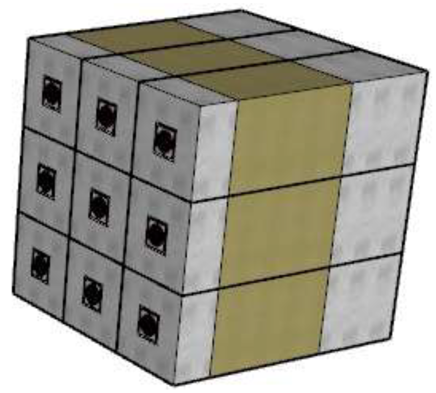
The wall component without 5G antenna in this study has a typical sandwich structure, as shown in Figure 1 below:
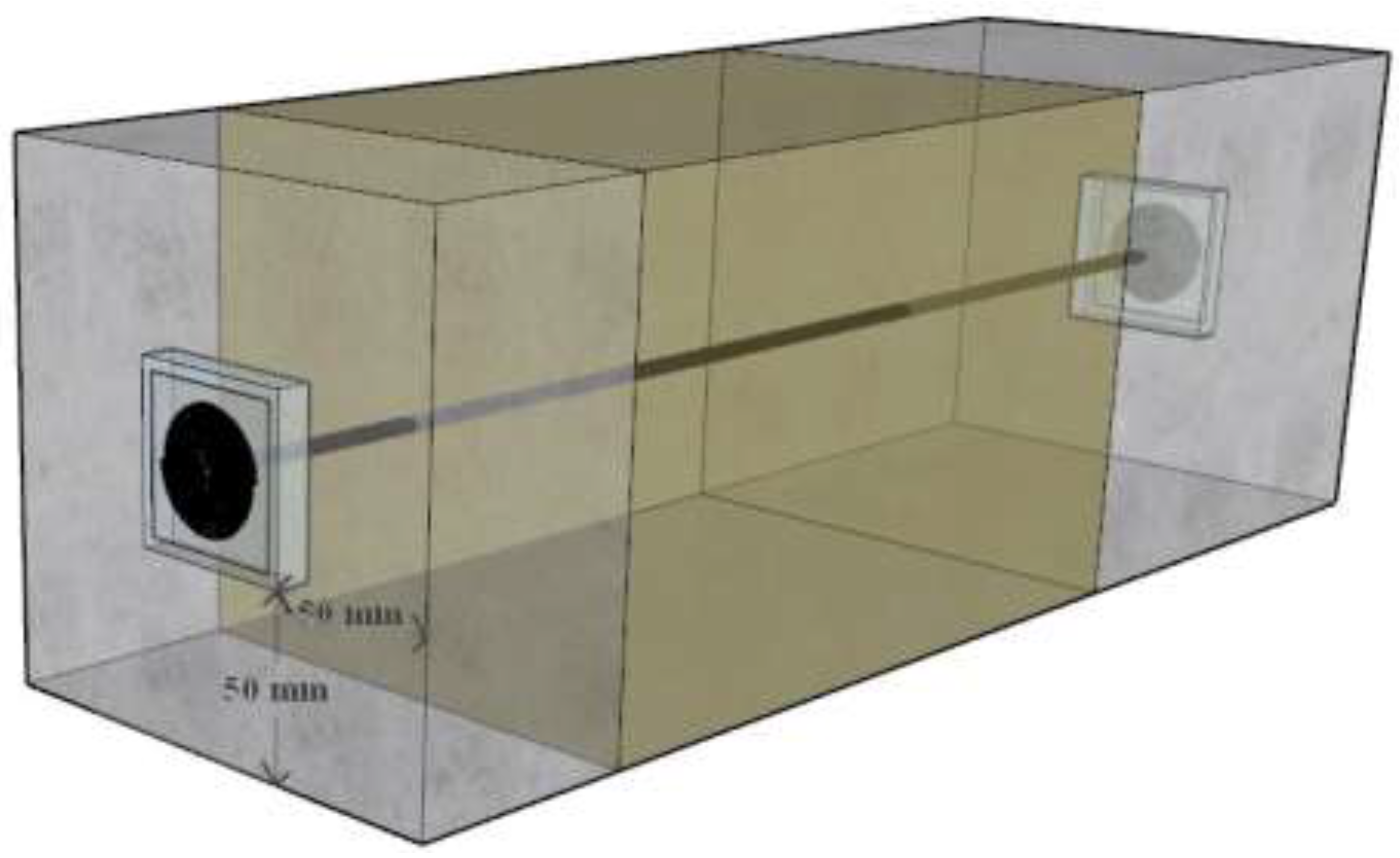
For simplicity, the wall component depicted in Figure 1 is referred to as the “sandwich wall” in this paper. The developed ultrawideband back-to-back spiral antenna system (Figure 2) was integrated into the sandwich wall (Figure 1) to create the “signal-transmissive wall” (Figure 3) [15].
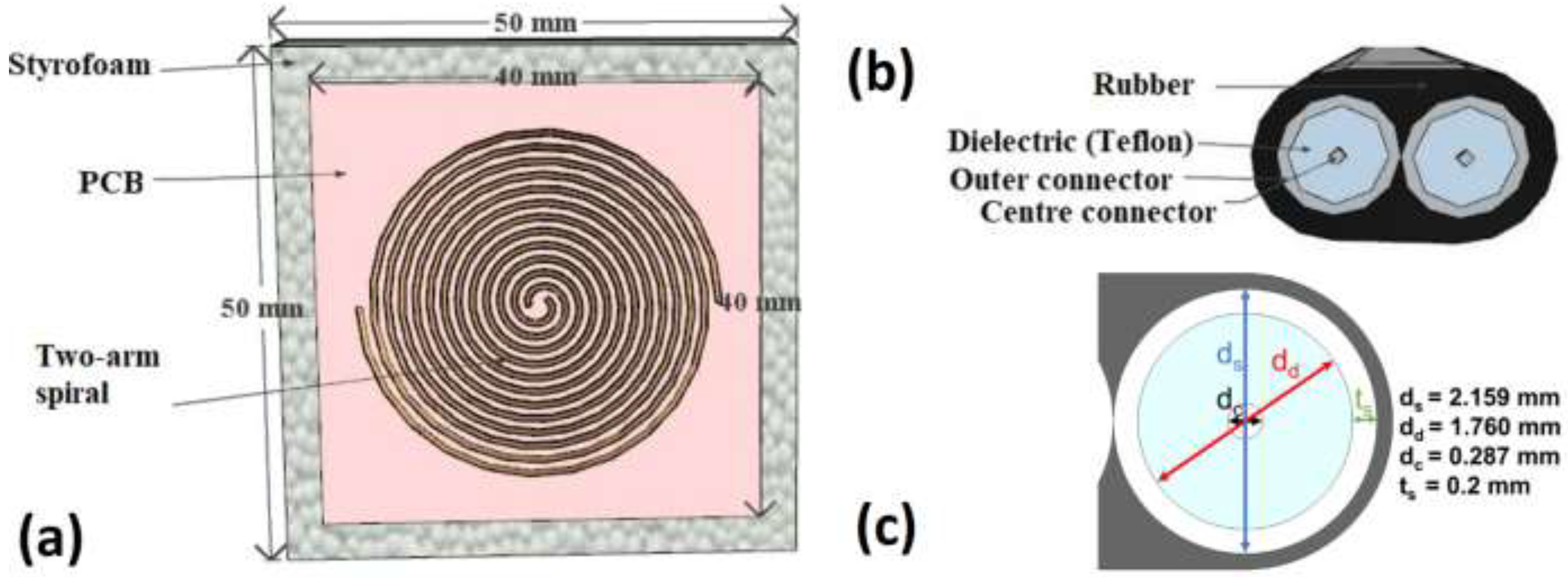
Figure 4 shows the cutaway of the ultrawideband back-to-back spiral antenna system (Figure 1).
A spiral antenna, shown in Figure 4, consists of a copper two-arm spiral (0.035 mm thick, outer radius 17.4 mm, and inner radius 1.08 mm), a Rogers RT/Duroid 5880 PCB (0.5 mm thick), and a Styrofoam board (10 mm thick). The semirigid dual coaxial cable is composed of a rubber block (6.5 mm2) and two coaxial cables. Each coaxial cable includes a stainless steel outer connector (0.2 mm thick and 2.159 mm diameter), a PTFE (Teflon) dielectric block (diameter 1.76 mm), and a stainless steel center connector (0.287 mm diameter). The two center connectors (440 mm long) are connected to the spiral arms, while the rest of the dual coaxial cable elements (439 mm long) touch the PCBs. The PCB is embedded in the Styrofoam board at the same level as the concrete (Figure 3). Table 1 lists the material properties of the sandwich and signal-transmissive walls.
This study did not take into account PCB finishes because their thermal impact is negligible due to their extremely thin layers. The illustration in Figure 3 shows that a 5G antenna should be placed in every 150 mm × 150 mm area within an external wall. However, the size can be increased to mitigate the thermal effects of the antennae on the wall, which is the subject of ongoing research.
In the building industry, the U-value of a wall is used to describe how well or how badly the wall transmits heat from the inside to the outside. In general, we expect a lower U-value, meaning that for every degree (K) of the temperature difference between the inside and outside, the wall loses less heat per square meter. Often, the heat flow through a wall is approximately one-dimensional [32]. However, the installation of a 5G antenna system in the sandwich wall (Figure 3) may cause a thermal bridging effect, which is a 3D heat flow and results in a higher U-value. To evaluate the thermal impact of the 5G antenna system on the sandwich wall, this study applied numerical modeling to estimate U-values primarily for three wall models: the sandwich wall (Figure 1), the signal-transmissive wall with outer and center connectors composed of stainless steel (i.e., the current design) (Figure 3 and Figure 4), and the signal-transmissive wall with outer and center connectors composed of copper (i.e., the previous design) (Figure 3 and Figure 4). Additionally, the study used three analytical methods, the parallel path, the isothermal planes, and the ISO 6946 combined methods, to calculate U-values for the three wall models, and the results were compared with the numerical results to determine a more reliable and accurate method to be used as a tool for future research. Section 2.2 and Section 2.3 describe the three analytical methods and 3D numerical modeling, while Section 3 presents their results.

2.2. Analytical Approaches

The U-value (W/m2K) of a building component is calculated using the following formula [22]:
U = 1 R T
where R T is the total thermal resistance of the building component (m2K/W). If the building component is constituted of homogeneous and parallel layers, R T is computed as [22]:
R T = R s i + j N R j + R s e = ( T i T o ) q
where R s i and R s e are the internal and external surface resistance (m2K/W), R j is the thermal resistance of layer j (m2K/W), T i and T o are the inside and outside temperatures (°C), and q is the heat flux through the building component (W/m2). R s i , R s e , and R j are given as:
R s i = 1 h s i , R s e = 1 h s e , R j = l j k j
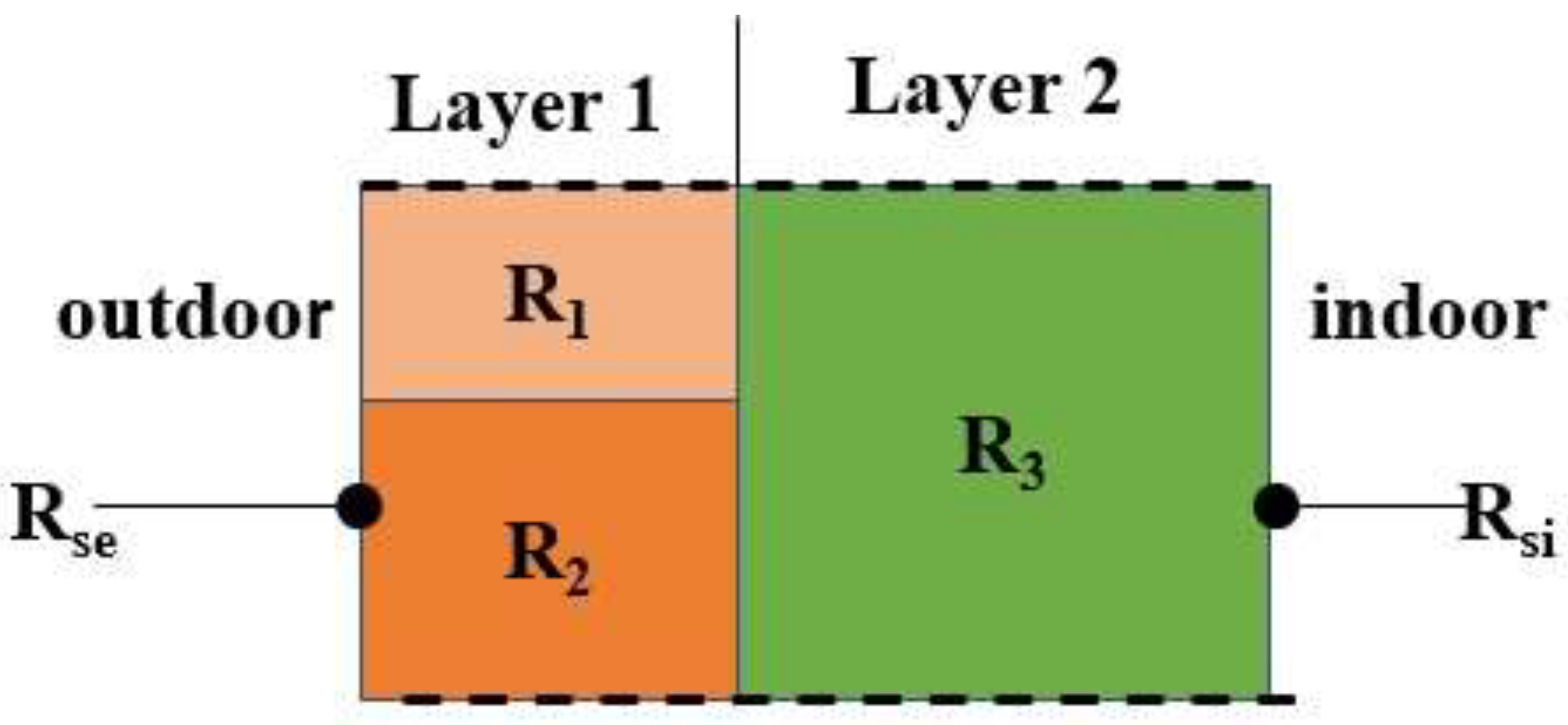
where h s i and h s e are the indoor and outdoor heat transfer coefficients (W/m2K), k j is the thermal conductivity of layer j (W/mK), and l j is the thickness of layer j (m). h s i and h s e are the normally set as 4 (W/m2K) and 25 (W/m2K) in Finland. There are several analytical methods available for calculating the U-values of building components with inhomogeneous layers [24]. In this study, we present three commonly used methods: the parallel path, the isothermal planes, and ISO 6946 combined methods. To illustrate the implementation of these methods, we use an example wall (as depicted in Figure 5) in the subsequent subsections.

2.2.1. Parallel Path Method

The parallel path method assumes that the heat transfer is perpendicular to the planes of building elements, meaning that the thermal network is composed of several parallel branches. This method is suitable for building components where the materials have close thermal conductivity values within the same layer [24]. For the sample wall in Figure 5, two flow paths can be identified (Figure 6).
In Figure 6, the total thermal resistance ( R T p a r a l l e l ) is:
U p a r a l l e l = 1 R T p a r a l l e l = f A ( R s e + R 1 + R 3 + R s i ) + f B ( R s e + R 2 + R 3 + R s i )
where U p a r a l l e l is the U-value (W/m2K), f A and f B are the fractions of the entire cross area occupied by sections A and B, respectively.

2.2.2. Isothermal Planes Method

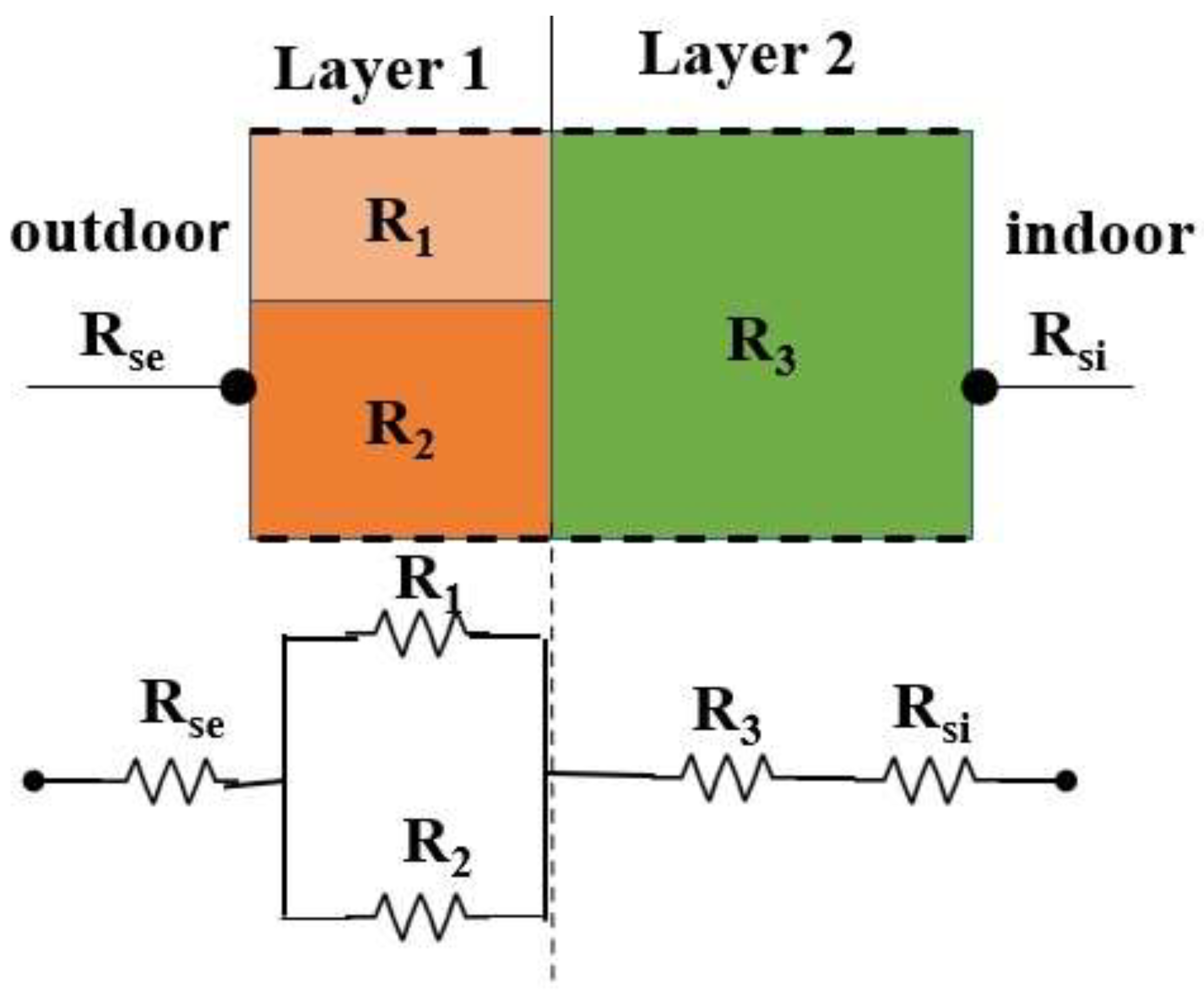
In the isothermal planes method, it is assumed that all surfaces parallel to the building element surfaces are isothermal, allowing heat to transfer laterally in any element. The thermal resistances of adjacent elements are combined in parallel, creating series-parallel paths [23]. This method is appropriate for situations where adjacent materials in the same layer have moderately differing conductivity [24]. Figure 7 illustrates the isothermal planes method for the sample wall (Figure 5).
The total thermal resistance ( R T i s o t h e r m a l ) is:
R T i s o t h e r m a l = R s e + 1 ( 1 R 1 + 1 R 2 ) + R 3 + R s i
Then the U-value ( U i s o t h e r m a l ) is:
U i s o t h e r m a l = 1 R T i s o t h e r m a l = 1 ( R s e + 1 ( 1 R 1 + 1 R 2 ) + R 3 + R s i )

2.2.3. ISO 6946 Combined Method

According to previous research, the overall thermal resistance calculated by the parallel path method is typically higher than that computed by the isothermal planes method, with the actual overall thermal resistance falling between the two [24]. The ISO 6946 combined method, which is described in the international standard ISO 6946 [22], calculates the overall thermal resistance as an arithmetic average of the thermal resistances computed by the parallel path and isothermal planes methods, namely:
R T I S O = R T p a r a l l e l + R T i s o t h e r m a l 2
where R T I S O , R T p a r a l l e l and R T i s o t h e r m a l are the calculated (overall) thermal resistances of the sample wall (Figure 5) by the ISO 6946 combined, parallel path, and isothermal planes methods, separately. The U-value ( U I S O ) is:
U I S O = 1 R T I S O = 2 R T p a r a l l e l + R T i s o t h e r m a l = 2 . U p a r a l l e l · U i s o t h e r m a l U p a r a l l e l + U i s o t h e r m a l
where U p a r a l l e l and U i s o t h e r m a l are the calculated U-values by the parallel path and isothermal planes methods, respectively.

2.3. Numerical Approach

COMSOL Multiphysics 6.1 was used to perform 3D thermal finite element simulations [33]. The “3D Heat Transfer in Solids” module was chosen to construct steady-state models for the sandwich wall (as shown in Figure 1) and the signal-transmissive walls (as shown in Figure 3, including both the current and previous designs). The boundary conditions were applied as depicted in Figure 8.
Convective heat transfer was selected for the exterior and interior surfaces, with outdoor and indoor temperatures set at −10 °C and 20 °C, respectively. In the U-value calculation for a wall sample, it is generally assumed that a steady-state condition exists [22]. Therefore, convective heat transfer coefficients were maintained constant in this study (see Figure 8). The edge faces (total of four) were treated as insulated. For each wall examined, the U-value was calculated, which is independent of the type of heat transfer and the temperature setting for the exterior and interior surfaces. The choice of convective heat transfer and ∆T = 30 °C (=20 °C–(−10 °C)) was for convenience. Equations (1) and (2) were utilized to compute the U-values of the walls. Swept meshing was used for meshing the two-arm spirals in the signal-transmissive walls, as their thickness was too small for traditional meshing methods [33]. The triangular meshes for the remaining elements in the signal-transmissive walls were created manually with different element size settings to accommodate thin areas. Automatic meshing with triangular elements was carried out for the sandwich wall. COMSOL provides a feature of adaptive mesh refinement, which enhances the mesh during simulation to minimize the global error in the model [33]. We utilized this feature for numerical modeling in this work.
In practice, a signal-transmissive wall (as illustrated in Figure 3) can be regarded as a cell of a 5G antenna external wall, and a 5G antenna external wall consists of numerous such cells. Apart from the three wall models examined in this paper (Section 2.1), we present an additional wall model to broaden our investigation to walls with multiple antennas. The additional wall model is a 5G antenna external wall made up of nine cells arranged in a 3 × 3 grid, as illustrated in Figure 9. We refer to this specific 5G antenna wall as a 3 × 3 signal-transmissive wall throughout this paper. On the other hand, a sandwich wall that features only one 5G antenna is commonly known as a “signal-transmissive wall” and is illustrated in Figure 3.
The boundary conditions applied to the 3 × 3 signal-transmissive walls in numerical modeling are identical to those used for sandwich and signal-transmissive walls.

3. Results and Discussion

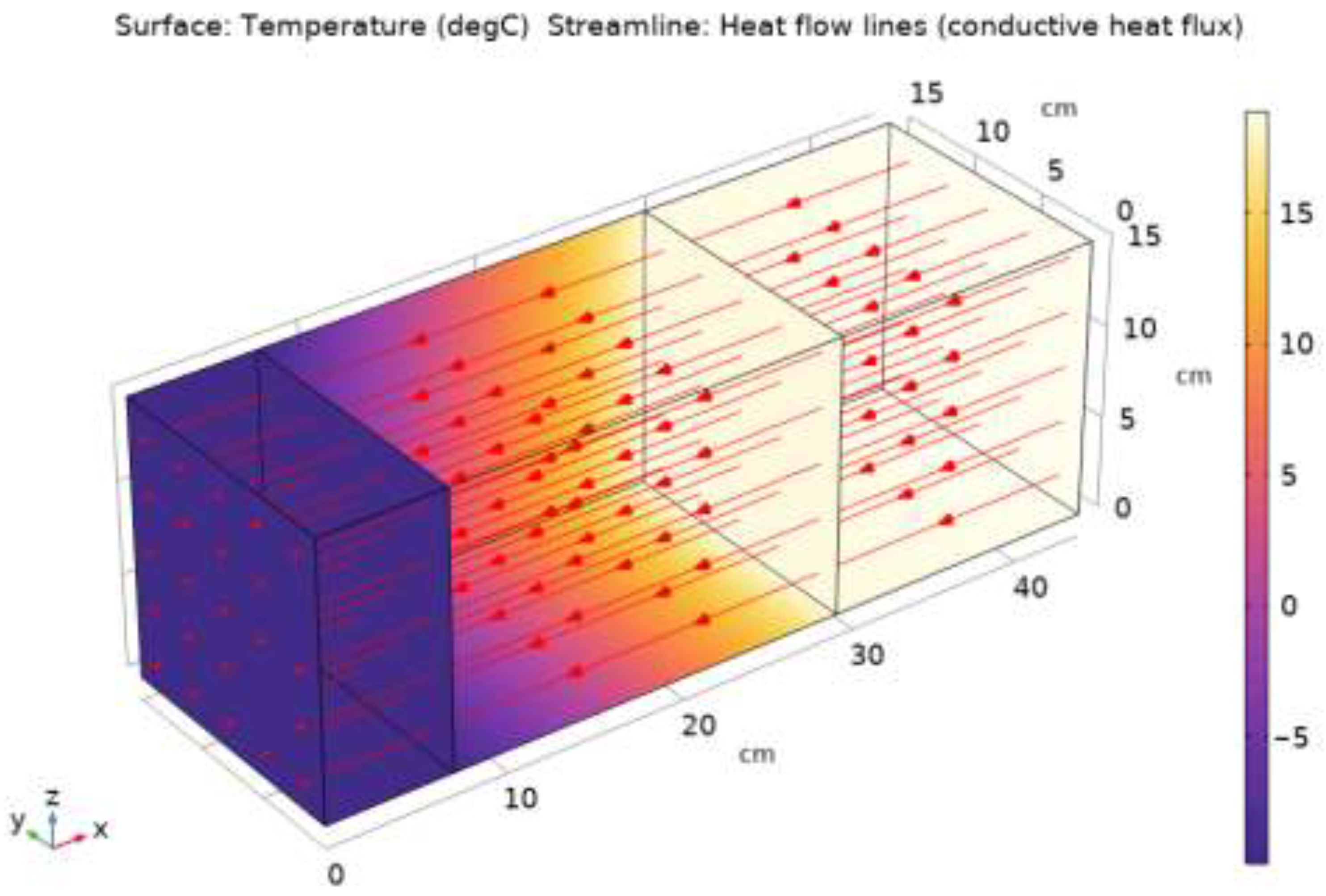
According to Table 1 and Equation (1)–(3), the U-value of the sandwich wall (Figure 1) was calculated to be 0.1496 W/m2K using the analytical approach. The numerical approach produced the same U-value of 0.1496 W/m2K, indicating that the simulation settings, including the boundary conditions, were appropriate for numerical modeling. Figure 10 displays the heat flow lines (i.e., heat flux) and temperature distribution of the sandwich wall in COMSOL Multiphysics.
As depicted in Figure 10, in the sandwich wall, the heat flow direction is perpendicular to the planes of the building elements, and these planes are almost isothermal.

3.1. Signal-Transmissive Walls

When using the parallel path and isothermal planes methods to compute the U-values of the signal-transmissive walls, the two-arm spirals were omitted due to their extremely small thickness (0.035 mm) and high thermal conductivity of copper (400 W/mK), resulting in an insignificant thermal resistance. Table 2 shows the comparison of U-values between the analytical and numerical approaches for the signal-transmissive walls. Copper is the most used connector material in coaxial cables, while other materials are not widely available. This is why we compare both copper and stainless-steel conductors in this work.
The 3D thermal finite element simulations in the steady state produced U-values of 1.56 W/m2K and 0.3 W/m2K for the current design (using stainless steel as connector materials) and previous design (using copper as connector materials), respectively, compared to the U-value of 0.1496 W/m2K for the sandwich wall. The previous work [15] reported a U-value of 0.16 W/m2K for a signal-transmissive wall with stainless-steel connectors, which is very similar to the current design discussed in this paper. This U-value was obtained through numerical modeling in a master’s thesis. The difference between the U-value reported in the previous work [15] and the U-value calculated in this study is only approximately +0.003 W/m2K, which is small and likely due to differences in thermal conductivity values for the same materials and differences in the internal convective heat transfer coefficient value. Furthermore, the U-values obtained from all three analytical methods employed in this study, namely the parallel path, isothermal planes, and ISO 6946 combined methods, were comparable to the U-value derived from numerical modeling for the current design, as demonstrated in Table 2. Most importantly, according to ASHRAE [24], the actual U-value for a building component containing inhomogeneous layers generally is some value between the U-values obtained using the parallel path and isothermal planes methods. For the current design, the actual U-value is expected to be between 1.53 and 1.57 W/m2K, and our estimation of U = 1.56 W/m2K using COMSOL Multiphysics falls exactly within this range, providing further validation for our numerical models of signal-transmissive walls.
In designing the signal-transmissive walls, copper was initially used as the connector material, but was later replaced by stainless steel in an effort to reduce thermal bridging effects caused by the 5G antenna. The results in Table 2 confirm the success of this change, as the U-value decreased to 0.156 W/m2K, which is below the maximum U-value recommended by the National Building Code of Finland (i.e., U = 0.17) [34] for external walls. The increase in U-value is a small amount, 0.0064 W/m2K (=0.156–0.1496). The heating degree day (HDD) method (as described in Equation (9)) was used to calculate the heat loss and cost associated with this increase in U-value (i.e., 0.0064 W/m2K).
Q w a l l _ h e a t _ l o s s = ( U . 24 . H D D ) / 1000
where Q w a l l _ h e a t _ l o s s is the heat loss through the wall per year (KWh/m2), U is the U-value (W/m2K), 24 is the conversion factor (h/d), and HDD are the heating degree days a year (Kd/a). Annual heating degree days and district heating price in Helsinki were assumed to be 3547 °C d/a (averaged value from 2008 to 2022; the effective indoor temperature is 17 °C) [35] and 11.35 cents/KWh [36]. The simulation results indicated that the current design requires only an additional 0.545 KWh/m2 of heating energy per year, resulting in a cost of approximately 0.062 EUR/m2 per year. This cost is considered negligible. On the other hand, the previous design had an additional heat loss of 12.8 KWh/m2 per year and a cost of 1.45 euros/m2 per year, which was 23.5 times greater than the current design. The current design has greatly reduced thermal bridging effects.
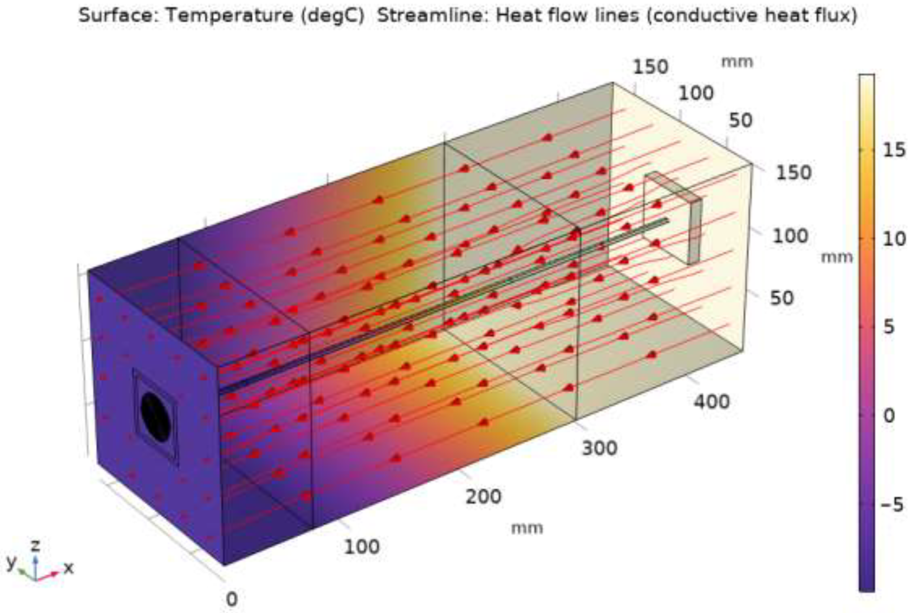
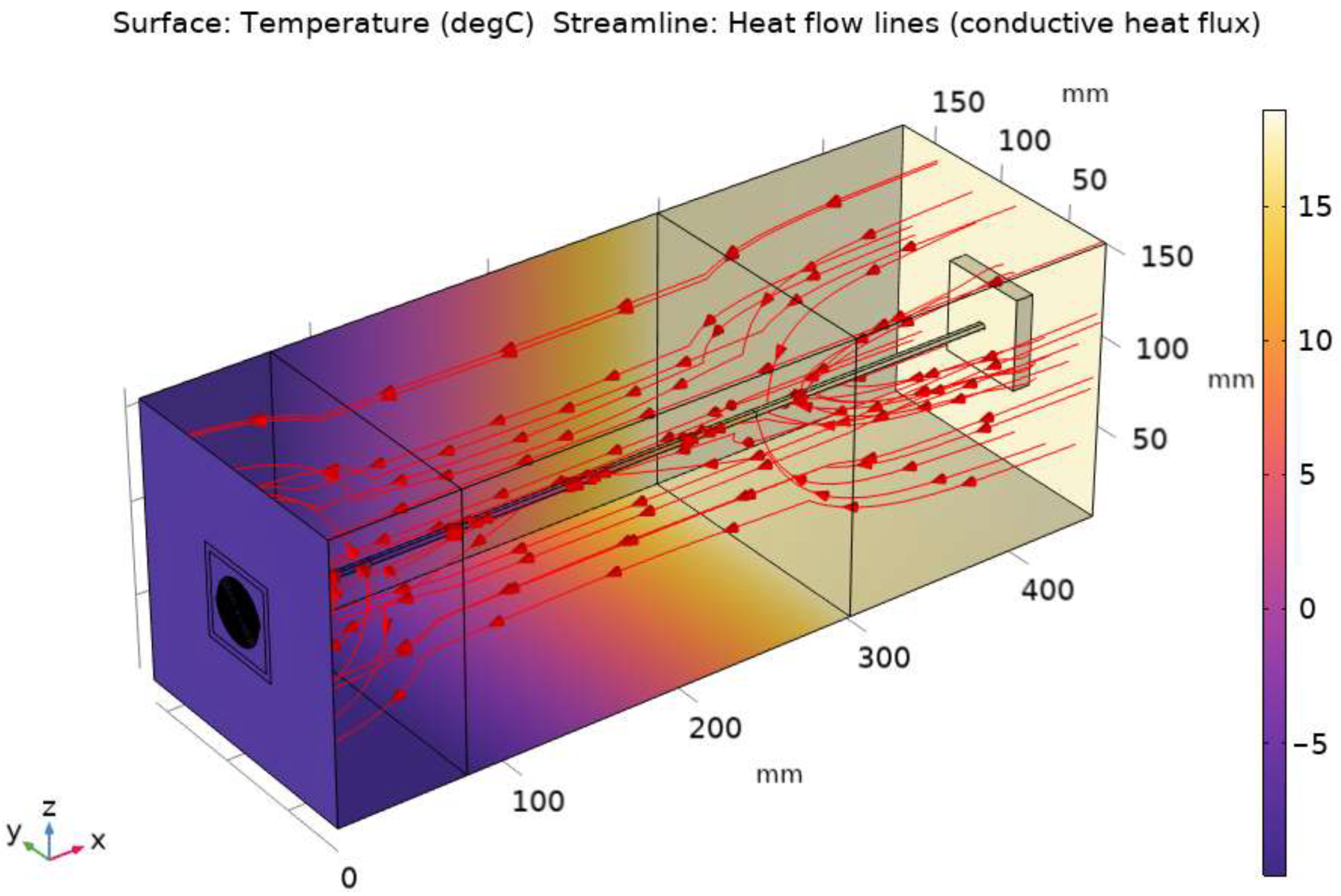
Figure 11 and Figure 12 display the results of heat flow lines and temperature distributions of signal-transmissive walls in COMSOL Multiphysics.
Compared to the heat flow lines in the sandwich wall (as shown in Figure 10), the observations from Figure 11 and Figure 12 are as follows:
  • In the current design, it can be assumed that the heat flows perpendicular to the planes of the building elements. However, in the previous design, the heat flow direction was no longer perpendicular to the planes of the building elements.
  • Unlike the current design, in the previous design (Figure 12), the distribution of heat flow lines varied between different layers. For instance, in the insulation layer, the heat flow lines are distributed closer to the dual coaxial cable compared to other layers. This is because the thermal resistance of rockwool is much higher than that of the dual coaxial cable, which used copper as a center connector material.
The above observations further confirm the previous conclusion that the current design minimizes the thermal bridging effect. Furthermore, the observations also suggest that the isothermal planes method is more appropriate than the parallel path method for determining the U-values of signal-transmissive walls. In an inhomogeneous layer, there can be significant changes in heat transfer paths if the thermal conductivity contrast between its materials is much higher than that of its adjacent layers (e.g., for the previous design). The parallel path method does not take this fact into account, while the isothermal planes method does. In the isothermal planes method, heat transfer paths are reallocated layer by layer. If the U-values estimated by COMSOL Multiphysics are taken as target values, the percentage errors generated by the three analytical methods are as follows (=(calculated U-value by analytical approach—U-value by COMSOL) * 100/U-value by COMSOL):
  • For the current design (Table 2): −1.9% (parallel path), +0.64% (isothermal planes), and −0.64% (ISO 6946 combined).
  • For the previous design (Table 2): −42.3% (parallel path), +6.7% (isothermal planes), and −25% (ISO 6946 combined).
For the current design, all three analytical methods produced good accuracies, with the isothermal planes and ISO 6946 combined methods slightly outperforming the parallel path method. However, for the previous design, the isothermal planes method significantly outperformed the other two methods. The National Building Code of Finland [34] employs the isothermal planes method in calculating the thermal resistances of inhomogeneous layers. Additionally, ASHRAE [24] and the National Building Code of Finland [34] provided more complex methods for situations where thermal bridging effects were substantial.

3.2. Three by Three Signal-Transmissive Walls

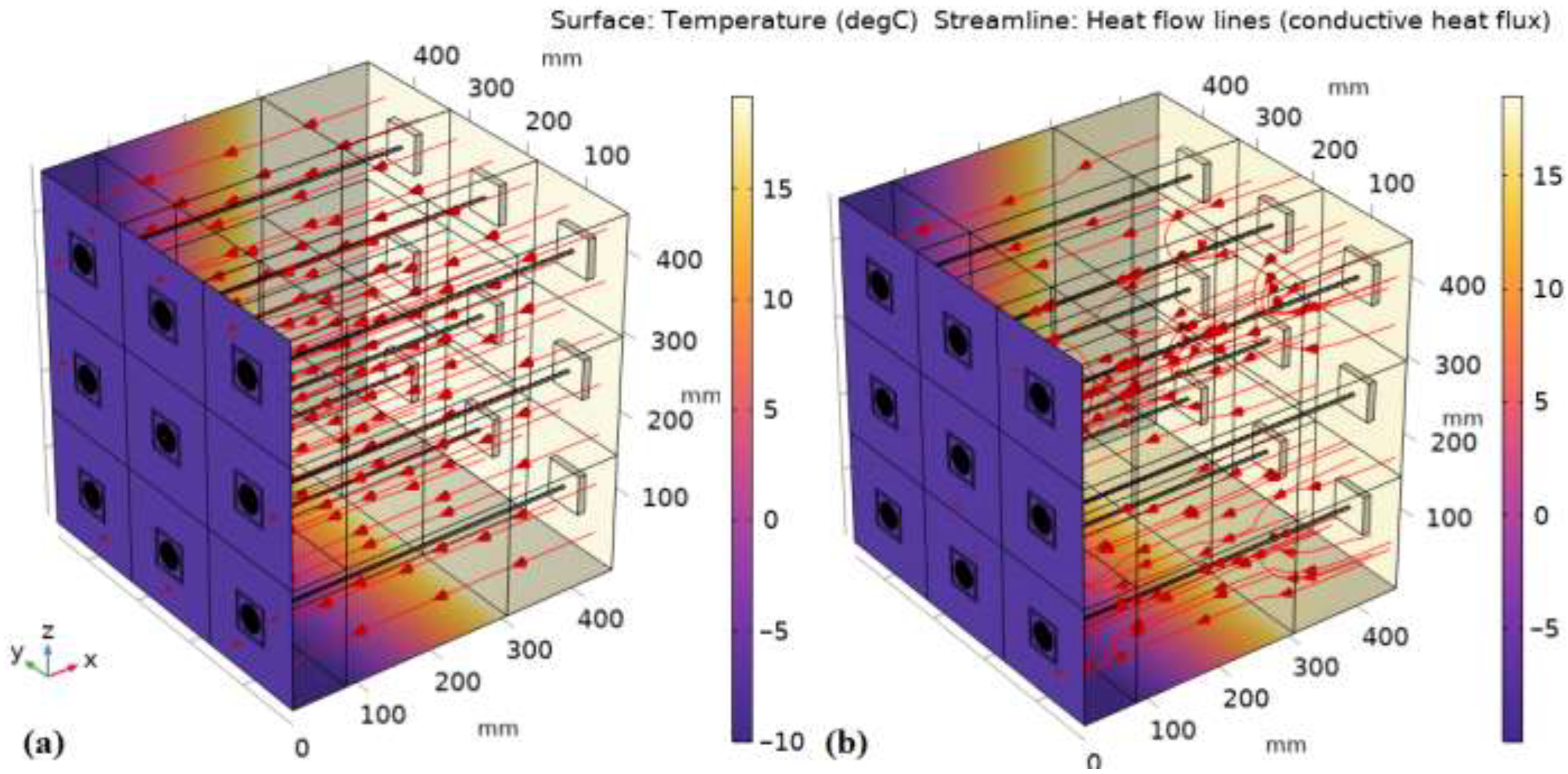
Figure 13 shows heat flow lines and temperature distributions of 3 × 3 signal-transmissive walls in COMSOL Multiphysics.
The heat flow patterns in 3 × 3 signal-transmissive walls exhibit comparable trends to those depicted in Figure 11 and Figure 12 for standalone signal-transmissive walls. Specifically, for the current design, heat flows in a direction almost perpendicular to the building element planes, unlike the previous design. Moreover, the results revealed that the heat flow patterns of individual cells (a cell is a signal-transmissive wall depicted in Figure 3) within 3 × 3 signal-transmissive walls remain consistent with those observed in standalone signal-transmissive walls. Using the numerical approach, the overall U-values for the 3 × 3 signal-transmissive walls, including all cells, were determined to be identical to those presented in Table 2, which were 0.156 and 0.3 W/m2K for the current and previous designs, respectively. The U-values calculated via theoretical approaches were also the same as those listed in Table 2. The average (normal) conductive heat fluxes on the interior surfaces of the nine cells ranged from 4.68 to 4.73 W/m for the current design, and from 8.83 to 8.90 W/m for the previous design, indicating proximity between the nine cells.
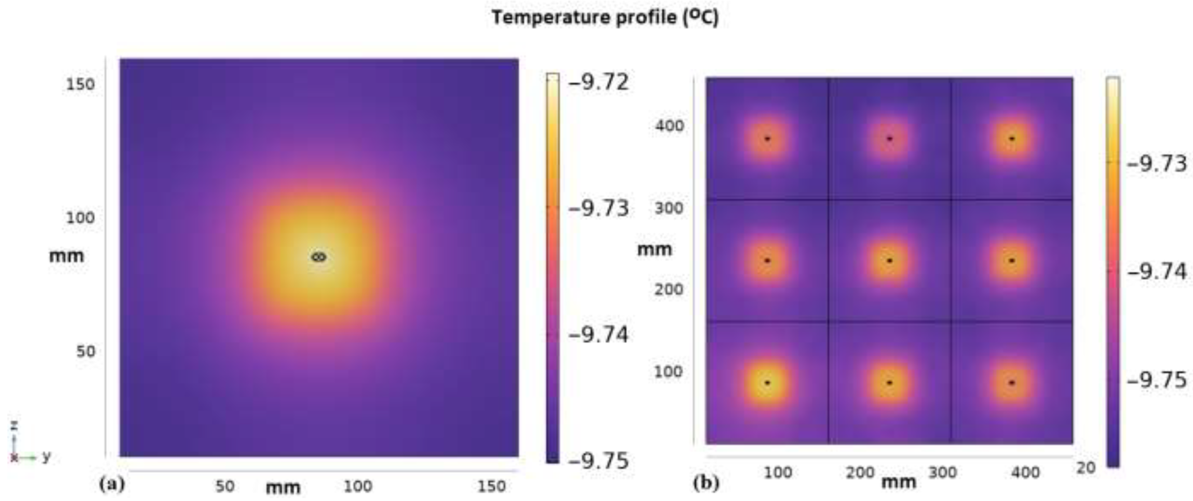
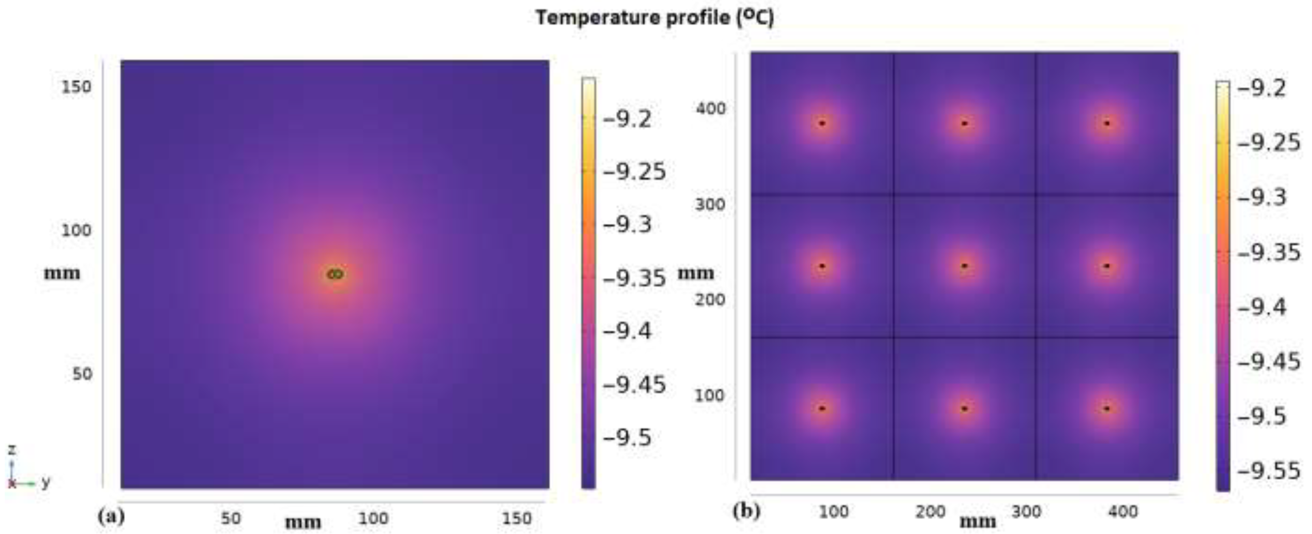
Figure 11, Figure 12 and Figure 13 do not display a temperature profile for any plane inside the walls, so to address this concern, we selected a cut plane that is situated 20 mm from the exterior surface of a wall to showcase the temperature profiles for signal-transmissive and 3 × 3 signal-transmissive walls (refer to Figure 14 and Figure 15). This cut-plane is positioned in the outer concrete layer. As evidenced by Figure 12 and Figure 13, the heat flow in the concrete layers is more disorderly than that in the insulation layer.
Some observations have been made from Figure 14 and Figure 15, as well as from analyzing temperature profiles from various cut planes situated in different layers (not shown here due to space limitations):
  • The current design (shown in Figure 14) has an insignificant thermal bridging effect, as the maximum temperature difference is less than 0.04 °C. However, the previous design exhibits clear thermal bridging effects with a maximum temperature difference of approximately 0.4 °C, as presented in Figure 15.
  • The thermal bridging effect, as depicted in Figure 15, affects an area larger than that of a dual coaxial cable but smaller than the cell size of 150 mm × 150 mm. This observation is probably applicable to all planes that are perpendicular to the building elements.
  • The thermal bridging effect, although small, cannot be disregarded in some planes of the current design.
  • There is no evidence to suggest that the thermal behavior of a cell is dependent on its location in the 3 × 3 signal-transmissive wall. This is supported by the fact that all nine cells in a 3 × 3 signal-transmissive wall were found to have similar average surface conductive heat fluxes (Figure 13), and their temperature profiles for cut planes are also very similar and closely resemble those of standalone signal-transmissive walls (as demonstrated in Figure 15).
However, more investigation is necessary to validate these findings (see Section 4 for future work).

4. Conclusions

In this work, the 3D finite element method was used to perform steady-state thermal analysis primarily on three types of walls: the sandwich wall, the signal-transmissive wall using stainless steel as connector material (the current design), and the signal-transmissive wall using copper as connector material (the previous design). Compared to the sandwich wall (with a U-value of 0.1496 W/m2K), the current design slightly increased the U-value to 0.156 W/m2K, which is below the maximum recommended U-value of 0.17 W/m2K for external walls specified by the National Building Code of Finland. The building energy simulation showed that in Helsinki, an increase in the U-value by 0.0064 W/m2K (from 0.1496 to 0.156), would result in only an additional external wall heat loss of 0.545 KWh/m2 per year (equivalent to approximately 0.062 euro/m2 per year if district heating is utilized). However, the previous design raised the U-value to 0.3 W/m2K, which greatly exceeded the U-value limit specified by the National Building Code of Finland, leading to an additional heat loss of 12.8 KWh/m2 per year (23.5 times that of the current design).
The 3D numerical models (Figure 11 and Figure 12) demonstrate a significant reduction in the thermal bridging effect from the previous design to the current design. Additionally, if a highly thermally conductive material, such as copper, is used for the center connectors in the signal-transmissive wall, heat flow may not always occur in a direction perpendicular to the building element planes. As a result, heat transfer paths could vary from layer to layer, leading to poor performance of the parallel path method. Furthermore, the results of comparing the U-values of signal-transmissive walls calculated using the parallel path, isothermal planes, and ISO 6946 combined methods showed that the isothermal planes method provided more accurate results.
In addition to the three wall models investigated in this work, thermal analysis was also conducted for a configuration of 3 × 3 signal-transmissive walls, consisting of nine signal-transmissive walls arranged in a 3 × 3 grid, using both numerical and theoretical methods. The calculated U-values for the 3 × 3 configuration were found to be the same as those for the standalone signal-transmissive walls. Additionally, it was observed that the areas affected by thermal bridging were generally smaller than the design dimensions of a signal-transmissive wall, which are 150 mm × 150 mm.
In the future, we plan to conduct a 3D transient heat transfer simulation for an apartment with partially signal-transmissive external walls. Currently, performing such a simulation is difficult due to the high computational demand, and it may require the use of supercomputing in the future.
Material choices affect both the thermal and electromagnetic properties of the signal-transmissive wall. The use of material with higher electrical conductivity would improve the electromagnetic transmission of the system. In the future, we need to study how materials, such as copper could be used in coaxial cable assemblies without compromising thermal insulation. Furthermore, the use of foldable coaxial cable assemblies should be studied. By folding the coaxial cable, the heat transfer should be smaller, which makes it possible to use other materials than stainless steel in the antenna system. Additionally, protecting antennas against changing operational conditions of weather, temperature, and humidity over the years of a building’s life cycle is an important future study. Holistic comparisons of active and passive antenna solutions will determine the actual solutions to be deployed in zero-energy buildings. The ability of building walls to keep thermal insulation while reducing electromagnetic insulation is one of the important key performance indicators of such antenna solutions.
Smart materials are embedded with sensors, electronics, or other technologies to enhance building performance by monitoring, controlling, and communicating with building systems and occupants [37]. The proposed antenna shows promise and could be included in smart material-based systems. Future research will also investigate the challenges related to smart antennas, including directional beamforming. By utilizing beamforming technology to focus the radiation pattern on the user’s device, the 5G antenna can maintain a stable and high-quality connection while delivering the signal more efficiently.

Author Contributions

Conceptualization, K.H. and L.V.-S.; methodology, T.L. and X.L.; software, T.L.; validation, T.L. and X.L.; formal analysis, T.L.; investigation, X.L., K.H. and L.V.-S.; resources, K.H. and X.L.; writing—original draft preparation, T.L.; writing—review and editing, K.H., L.V.-S. and X.L.; visualization, T.L.; supervision, X.L.; project administration, K.H. and X.L.; funding acquisition, K.H. and X.L. All authors have read and agreed to the published version of the manuscript.

Funding

This research was funded by the Academy of Finland, project STARCLUB, grant number 324023.

Data Availability Statement

Not applicable.

Acknowledgments

We thank Derek Clements-Croome for the editing assistance.

Conflicts of Interest

The authors declare no conflict of interest.

References

  1. Wikipedia. “5G”. Available online: https://en.wikipedia.org/wiki/5G (accessed on 1 February 2023).
  2. Gallagher, J.C.; DeVine, M.E. Fifth-Generation (5G) Telecommunications Technologies: Issues for Congress; CRS Report; Congressional Research Service: Washington, DC, USA, 2019.
  3. Nokia. 5G Deployment below 6 GHz Ubiquitous Coverage for Critical Communication and Massive IoT; White paper; Nokia: Espoo, Finland, 2018. [Google Scholar]
  4. Rodriguez, I.; Nguyen, H.C.; Jorgensen, N.T.K.; Sorensen, T.B.; Mogensen, P. Radio propagation into modern buildings: Attenuation measurements in the range from 800 MHz to 18 GHz. In Proceedings of the 2014 IEEE 80th Vehicular Technology Conference (VTC2014-Fall), Vancouver, BC, Canada, 14–17 September 2014; pp. 1–5. [Google Scholar]
  5. Haneda, K.; Zhang, J.; Tan, L.; Liu, G.; Zheng, Y.; Asplund, H.; Li, J.; Wang, Y.; Steer, D.; Li, C.; et al. 5G 3GPP-like channel models for outdoor urban microcellular and macrocellular environments. In Proceedings of the 2016 IEEE 83rd Vehicular Technology Conference (VTC Spring), Nanjing, China, 15–18 May 2016; pp. 1–7. [Google Scholar]
  6. Er-reguig, Z.; Ammor, H. Towards designing a microcell base station using a software-defined radio platform. In Proceedings of the 2019 7th Mediterranean Congress of Telecommunications (CMT), Fez, Morocco, 24–25 October 2019; pp. 1–4. [Google Scholar]
  7. Yunas, S.F. Capacity, Energy-Efficiency and Cost-Efficiency Aspects of Future Mobile Network Deployment Solutions. Ph.D. Thesis, Tampere University of Technology, Tampere, Finland, 2015. [Google Scholar]
  8. Haneda, K.; Kahra, E.; Wyne, S.; Icheln, C.; Vainikainen, P. Measurement of loop-back interference channels for outdoor-to-indoor fullduplex radio relays. In Proceedings of the Fourth European Conference on Antennas and Propagation, Barcelona, Spain, 12–16 April 2010; pp. 1–5. [Google Scholar]
  9. Rigelsford, J.M.; Ford, K.L.; Subrt, L. A passive system for increasing cellular coverage within energy efficient buildings. In Proceedings of the 8th European Conference on Antennas and Propagation (EuCAP 2014), The Hague, The Netherlands, 6–11 April 2014; pp. 614–615. [Google Scholar]
  10. Ntontin, K.; Verikoukis, C. Relay-aided outdoor-to-indoor communication in millimeter-wave cellular networks. IEEE Syst. J. 2020, 14, 2473–2484. [Google Scholar] [CrossRef]
  11. Asp, A.; Baniya, A.; Yunas, S.F.; Niemelae, J.; Valkama, M. Applicability of frequency selective surfaces to enhance mobile network coverage in future energy-efficient built environments. In Proceedings of the European Wireless 2015, 21th European Wireless Conference, Budapest, Hungary, 20–22 May 2015; pp. 1–8. [Google Scholar]
  12. Lammin Windows & Doors. “Signal Window.”. Available online: http://signal-window.com (accessed on 1 February 2023).
  13. Lilja, J. Mobile-friendly glass –comparing solutions from the end user viewpoint. In Proceedings of the Glass Performance Days 2019 (GPD2019), Tampere, Finland, 26–28 June 2019. [Google Scholar]
  14. Vähä-Savo, L.; Atienza, A.G.; Cziezerski, C.; Heino, M.; Haneda, K.; Icheln, C.; Lü, X.; Viljanen, K. Passive antenna systems embedded into a load bearing wall for improved radio transparency. In Proceedings of the 2020 50th European Microwave Conference (EuMC), Utrecht, The Netherlands, 12–14 January 2021; pp. 424–427. [Google Scholar]
  15. Vähä-Savo, L.; Haneda, K.; Icheln, C.; Lü, X. Electromagnetic-Thermal Analyses of Distributed Antennas Embedded into a Load Bearing Wall. arXiv 2022, arXiv:2207.06185. [Google Scholar]
  16. ISO 9869; Thermal Insulation—Buildings Elements—In-Situ Measurement of Thermal Resistance and Thermal Transmittance—Part 1: Heat Flow Meter Method. ISO—International Organization for Standardization: Geneva, Switzerland, 2014.
  17. Salmon, D. Thermal conductivity of insulations using guarded hot plates including recent developments and sources of reference materials. Meas. Sci. Technol. 2001, 12, R89. [Google Scholar] [CrossRef]
  18. ISO 8990; Thermal Insulation—Determination of Steady-State Thermal Transmission Properties—Calibrated and Guarded Hot Box. ISO—International Organization for Standardization: Geneva, Switzerland, 1994.
  19. Soares, N.; Martins, C.; Gonçalves, M.; Santos, P.; da Silva, L.S.; Costa, J.J. Laboratory and in-situ non-destructive methods to evaluate the thermal transmittance and behaviour of walls, windows, and construction elements with innovative materials: A review. Energy Build. 2019, 182, 88–110. [Google Scholar] [CrossRef]
  20. Martins, C.; Santos, P.; da Silva, L.S. Lightweight steel-framed thermal bridges mitigation strategies: A parametric study. J. Build. Phys. 2016, 39, 342–372. [Google Scholar] [CrossRef]
  21. Santos, P.; Martins, C.; da Silva, L.S.; Bragança, L. Thermal performance of lightweight steel framed wall: The importance of flanking thermal losses. J. Build. Phys. 2014, 38, 81–98. [Google Scholar] [CrossRef] [Green Version]
  22. ISO 6946; Building Components and Building Elements—Thermal Resistance and Thermal Transmittance—Calculation Methods. ISO—International Organization for Standardization: Geneva, Switzerland, 2017.
  23. Kosny, J.; Christian, J.E.; Barbour, E.; Goodrow, J. Thermal Performance of Steel-Framed Walls; ORNL report; Oak Ridge National Laboratory: Oak Ridge, TN, USA, 1994.
  24. ASHRAE. Handbook of Fundamentals (SI Edition); ASHRAE—American Society of Heating, Refrigerating and Air-Conditioning Engineers: Atlanta, GA, USA, 2017. [Google Scholar]
  25. Christensen, D. Thermal Impact of Fasteners in High-Performance Wood-Framed Walls; National Renewable Energy Lab. (NREL): Golden, CO, USA, 2010.
  26. SolidWorks. Introducing COSMOSWorks; Structural Research and Analysis Corporation (SRAC): Los Angeles, CA, USA, 2003. [Google Scholar]
  27. Santos, P.; Lemes, G.; Mateus, D. Analytical Methods to Estimate the Thermal Transmittance of LSF Walls: Calculation Procedures Review and Accuracy Comparison. Energies 2020, 13, 840. [Google Scholar] [CrossRef] [Green Version]
  28. Muzzi, T.A.; Souza, H.A.; Gomes, A.P. Heat transfer analysis of the vertical closing system in light steel framing using the isothermal planes method and finite element method. REM Int. Eng. J. 2021, 74, 425–431. [Google Scholar] [CrossRef]
  29. Kosny, J.; Yarbrough, D.; Childs, P.; Mohiuddin, A. Effects of Framing on the Thermal Performance of Wood and Steel-Framed Walls. In Proceedings of the Fifteenth Symposium on Improving Building Systems in Hot and Humid Climates, Orlando, FL, USA, 24–26 July 2006. [Google Scholar]
  30. Gorgolewski, M. Developing a simplified method of calculating U-values in light steel framing. Build. Environ. 2007, 42, 230–236. [Google Scholar] [CrossRef]
  31. Atsonios, I.A.; Mandilaras, I.D.; Kontogeorgos, D.A.; Founti, M.A. Two new methods for the in-situ measurement of the overall thermal transmittance of cold frame lightweight steel-framed walls. Energy Build. 2018, 170, 183–194. [Google Scholar] [CrossRef]
  32. Hagentoft, C.E. Introduction to Building Physics; Studentlitteratur: Lund, Sweden, 2001. [Google Scholar]
  33. COMSOL. Heat Transfer Module User’s Guide; COMSOL Inc.: Stockholm, Sweden, 2022. [Google Scholar]
  34. Ministry of the Environment of Finland. Decree of the Ministry of the Environment on Thermal Insulation; Ministry of the Environment of Finland: Helsinki, Finland, 2003. [Google Scholar]
  35. Finnish Meteorological Institute. Heating Degree Days. Available online: https://en.ilmatieteenlaitos.fi/heating-degree-days (accessed on 2 February 2023).
  36. Helen. District Heating Prices. Available online: https://www.helen.fi/en/heating-and-cooling/district-heat/district-heat-prices (accessed on 2 February 2023).
  37. Fortuna, L.; Buscarino, A. Smart Materials. Materials 2022, 15, 6307. [Google Scholar] [CrossRef] [PubMed]
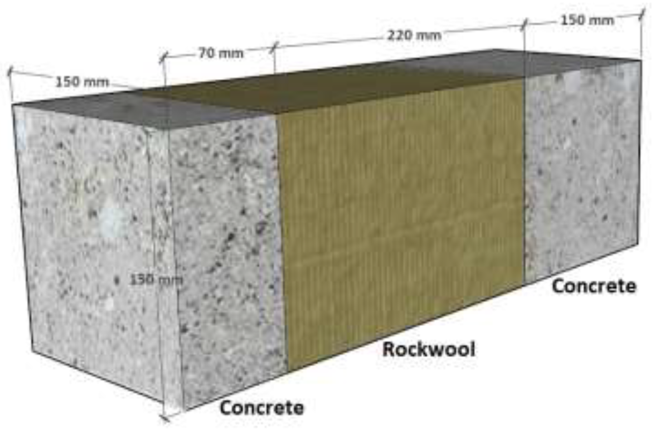
Figure 1. Sandwich wall: 70 mm concrete (outer layer), 220 mm rockwool (insulation layer), and 150 mm concrete (inner layer). The dimension is 150 mm × 150 mm.
Energies 16 02657 g001
Figure 2. Ultrawideband back-to-back spiral antenna system developed by the authors. The antenna system contains two identical spiral antennas and a semi-rigid dual coaxial cable.
Energies 16 02657 g002
Figure 3. Signal-transmissive wall.
Energies 16 02657 g003
Figure 4. (a) Spiral antenna; (b) semirigid dual coaxial cable (two coaxial cables are wrapped into a rubber tube); (c) dimensions of coaxial cable.
Energies 16 02657 g004
Figure 5. Two-layer wall. Layer 1 contains two different materials.
Energies 16 02657 g005
Figure 6. Illustration of parallel path method (left: thermal network; right: identified paths).
Energies 16 02657 g006
Figure 7. Illustration of isothermal planes method (bottom: the series-parallel thermal network obtained using the isothermal planes method).
Energies 16 02657 g007
Figure 8. Boundary conditions for 3D thermal finite element simulations (left: the sandwich wall: right: signal-transmissive wall). To and Ti are outdoor and indoor temperatures, while hse and hsi are indoor and outdoor heat transfer coefficients.
Energies 16 02657 g008
Figure 9. Illustrated is 3 × 3 signal-transmissive wall.
Energies 16 02657 g009
Figure 10. Heat flow lines generated by numerical modeling (COMSOL Multiphysics) for the sandwich wall.
Energies 16 02657 g010
Figure 11. Heat flow lines generated by numerical modeling (COMSOL Multiphysics) for the signal-transmissive wall with stainless steel as connector materials (current design).
Energies 16 02657 g011
Figure 12. Heat flow lines generated by numerical modeling (COMSOL Multiphysics) for the signal-transmissive wall with copper as connector materials (previous design).
Energies 16 02657 g012
Figure 13. Heat flow lines generated by numerical modeling (COMSOL Multiphysics) for (a) the 3 × 3 signal-transmissive wall with stainless steel as connector materials (current design), and (b) the 3 × 3 signal-transmissive wall with copper as connector materials (previous design).
Energies 16 02657 g013
Figure 14. Temperature profile for the cut plane, which is 20 mm away from the exterior surface: (a) Signal-transmissive wall (current design); (b) 3 × 3 signal-transmissive wall (current design).
Energies 16 02657 g014
Figure 15. Temperature profile for the cut plane, which is 22 mm away from the exterior surfaces: (a) Signal-transmissive wall (previous design); (b) 3 × 3 signal-transmissive wall (previous design).
Energies 16 02657 g015
Table 1. Wall and antenna material properties.
MaterialDensity (kg/m3)Thermal Conductivity
(W/mK)
Specific Heat
(J/kgK)
Concrete240021000
Rockwool1400.035840
Styrofoam150.041500
PCB22000.2960
Rubber8500.21900
Stainless steel800015.2500
PTFE (Teflon)20000.241500
Copper8960400385
Table 2. Calculated U-values for signal-transmissive walls.
Materials of ConnectorsU-Value (W/m2K)
COMSOL MultiphysicsStainless steel (current design) *0.156
Copper (previous design) **0.3
Parallel pathStainless steel (current design) *0.153
Copper (previous design) **0.173
Isothermal planesStainless steel (current design) *0.157
Copper (previous design) **0.32
ISO 6946 combinedStainless steel (current design) *0.155
Copper (previous design) **0.225
* Center and outer connectors were composed of stainless steel (Figure 4b). ** Center and outer connectors were composed of copper (Figure 4b).
Disclaimer/Publisher’s Note: The statements, opinions and data contained in all publications are solely those of the individual author(s) and contributor(s) and not of MDPI and/or the editor(s). MDPI and/or the editor(s) disclaim responsibility for any injury to people or property resulting from any ideas, methods, instructions or products referred to in the content.