Abstract
The integration of distributed generation (DG) into a power distribution network allows the establishment of a microgrid (MG) system when the main grid experiences a malfunction or is undergoing maintenance. In this case, the power-generating capacity of distributed generators may be less than the load demand. This study presents a strategy for the effective utilization of deployed active and reactive power sources under power mismatch conditions in the islanded distribution networks. Initially, the DGs’ and capacitors’ optimal placement and capacity were identified using the Jaya algorithm (JA) with the aim to reduce power losses in the grid-connected mode. Later, the DG and capacitor combination’s optimal power factor was determined to withstand the islanded distribution network’s highest possible power demand in the event of a power mismatch. To assess the optimal value of the DG–capacitor pair’s operating power factor () for the islanded operation, an analytical approach has been proposed that determines the best trade-off between power losses and the under-utilization of accessible generation. The test results on 33-bus and 69-bus IEEE distribution networks demonstrate that holding the islanded network’s load power factor () equal to during the power imbalance conditions allows the installed distributed sources to effectively operate at full capacity. As expected, the proposed strategy will assist the utility companies in designing efficient energy management or load shedding schemes to effectively cope with the power mismatch conditions.
1. Introduction
Obtaining favorable results by introducing distributed generation (DG) and capacitors into distribution networks necessitates a well-thought-out design strategy. The optimal positioning and sizing of capacitors and DGs potentially result in improved voltage stability, reliability, power quality, reduced power losses, and eliminating or deferring the upgrades of the electrical power networks. In addition, DGs’ and capacitors’ joint presence allows the distribution networks to be operated as autonomous grids whenever the primary grid faces a fault or is being serviced. In the recent literature, heuristic and meta-heuristic techniques have been commonly used to optimize the capacity and placement of DGs and capacitor units in the distribution networks. However, the literature focuses on identifying the DGs’ and capacitors’ simultaneous allocation for grid-integrated distribution networks.
Among the examined papers, two studies [1,2] in the literature have retrieved the pivotal option of microgrid (MG) formation, while allocating the DGs and capacitors in on-grid radial distribution networks. Gholami et al. [1] optimally allocated the capacitor units in DG-integrated power distribution networks for both on-grid and off-grid operation modes. Under islanded operation, the authors assumed that a section of the distribution system was operated with accessible energy. Nevertheless, they did not entail any method for fully operating the installed sources. Wang and Zhong [2] optimally allocate the capacitor and DG units both on the grid and in the islanded mode of the distribution system in order to boost voltage levels at network buses. However, the authors chose different DG and capacitor banks for both operation modes, and their placements changed when the operation mode switched, which is an unrealistic strategy. In one study, Yazdavar et al. [3] optimize the capacitor and DG sizes, locations, and types for a standalone MG that is not the part of central grid. Thus, the authors ignored both the grid-integrated and islanded modes of operation. In addition, while optimally allocating the DGs alone, a method for determining the best DG locations and sizes for islanded networks has been reported in a few studies [4,5,6]. However, the mentioned studies hypothesized that the DG units’ capacity was more than the total energy consumption (power losses and demand) and hence used the isolated operation approach to address islanded distribution networks.
Although islanded and isolated networks have nearly identical control and operational needs, they differ in planning, owing to the islanded mode’s short interval of MG operation [7]. The on-grid distribution networks typically operate in autonomous mode for a brief time when the primary grid experiences a fault or is undergoing maintenance. Therefore, the installation of larger DGs can ensure the sustainable operation of the electric grid. However, it will raise the overall cost of the power system, making the electric grid more complicated. Therefore, a mechanism must be developed to utilize the same installed DGs as a standby power source till the grid’s supply is restored. It will be possible if the installed DGs supply power to a specific distribution network section by dividing the entire network into several zones. Alternatively, if distribution system operators (DSOs) can persuade consumers to limit their electricity consumption, then at least a portion of each consumer’s load demand can be met with available energy. Hence, it is necessary to create a mechanism to fully utilize the installed DG and capacitor units to serve a significant part of the islanded network’s total load demand under supply–demand mismatch conditions. Such an approach will also allow the utilities to design effective energy conservation, load shedding, and demand-side management (DSM) schemes to improve the reliability of the islanded distribution networks when there is a supply–demand disparity (Figure 1). The systematic literature findings have been compiled in Table 1. In addition, in [8], the authors of this paper presented a detailed critical review of the studies that have been especially undertaken in the domain of simultaneous DG and capacitor allocation in the power distribution networks.
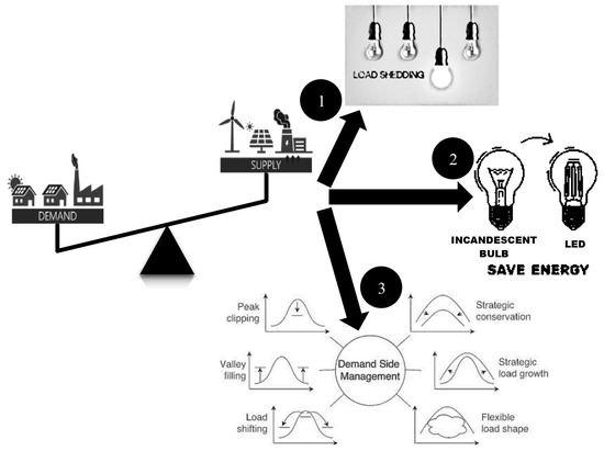
Figure 1.
Strategies to handle the supply–demand imbalance (Pdemand ≥ Psupply) condition.
Furthermore, in the literature, various studies [9,10] emphasize the risk of a total blackout and suggest restoration techniques that leverage distributed generation to restore critical loads, especially since shedding load is a critical method for handling power imbalance conditions when the power supply is less than the demand. Load shedding enables DSOs to allocate available energy to critical loads and discard the remaining load. However, an analysis of how the distributed sources’ available power generation capacity can be optimized to serve the maximum possible share of the total network load while minimizing load shedding is necessary to make an informed decision.

Table 1.
A literature review summary on optimal DG and capacitor placements in distribution systems.
Table 1.
A literature review summary on optimal DG and capacitor placements in distribution systems.
| Ref# | Author(s)/Year | Objective Function(s) | Optimization Technique(s) | Operation Mode(s) |
|---|---|---|---|---|
| [11] | Ahmad Eid (2022) | Active and reactive power loss, voltage deviation, and stability | Jellyfish search algorithm | Grid-connected |
| [12] | Mouwaf et al. (2022) | Active power loss, voltage deviation, and stability | Chaotic bat algorithm | Grid-connected |
| [13] | Leghari et al. (2022) | Active power loss and voltage deviation | Best–worst optimizers | Grid-connected |
| [14] | Naderipour et al. (2021) | Costs of energy loss, installation, and maintenance | Spotted hyena optimizer | Grid-connected |
| [15] | Malik et al. (2020) | Active power loss, voltage deviation, and voltage stability index | Multiobjective particle swarm optimization | Grid-connected |
| [16] | Tolabi et al. (2020) | Active power loss, voltage stability, and operational cost | Thief and police algorithm | Grid-connected |
| [17] | Almabsout et al. (2020) | Active power loss | Enhanced genetic algorithm | Grid-connected |
| [18] | Manikanta et al. (2019) | Active power loss | Quantum-inspired evaluation algorithm | Grid-connected |
| [19] | Sambaiah and Jayabarathi (2019) | Active power loss, voltage deviation, voltage stability index, installation and maintenance costs of DGs and capacitors, and gas emissions | Salp swarm algorithm | Grid-connected |
| [20] | Lotfi et al. (2018) | Active power loss | Particle swarm optimization and genetic algorithm | Grid-connected |
| [21] | Mehmood et al. (2018) | Energy loss index, voltage enhancement index, and investment cost index | Elitist speciation-based genetic algorithm | Grid-connected |
| [22] | Dixit et al. (2017) | Active power loss | Gbest-guided artificial bee colony | Grid-connected |
| [23] | Biswas et al. (2017) | Active and reactive power loss | Multiobjective evolutionary algorithm based on the decomposition | Grid-connected |
| [24] | Ghanegaonkar and Pande (2017) | Active power loss, energy loss, and capacitor switching events | Particle swarm optimization | Grid-connected |
| [25] | Kumar et al. (2017) | Active power loss, voltage deviation, and voltage stability index | Multiobjective particle swarm optimization | Grid-connected |
| [26] | Muthukumar and Jayalalitha (2016) | Active power loss | Hybrid harmony search—particle artificial bee colony algorithm | Grid-connected |
| [27] | Khodabakhshian and Andisghae (2016) | Cost of losses | Intersect mutation differential evolution | Grid-connected |
| [28] | Jannat and Savic (2016) | Voltage deviation and installed reactive power capacity | Non–dominated sorting genetic algorithm | Grid-connected |
| [29] | Lalitha et al. (2016) | Active power loss and voltage deviation | Symbiotic organisms search | Grid-connected |
| [30] | Andebili (2016) | Investment and maintenance costs of DGs and capacitors, cost of energy loss, and risk cost | Genetic algorithm | Grid-connected |
| [31] | Ghaffarzadeh and Sadeghi (2016) | The benefit of reductions in active power loss, reactive power loss, and power purchased from the grid | Biogeography-based optimization algorithm | Grid-connected |
| [32] | Pereira et al. (2016) | Investment costs of DGs and capacitors and system’s operation costs | Hybrid Tabu search-Chu-Beasly genetic algorithm | Grid-connected |
| [33] | Kayal and Chanda (2016) | Active power loss, voltage stability factor, network security index, economic index, and annual carbon dioxide emission | Non-dominated sorting multiobjective particle swarm optimization | Grid-connected |
| [34] | Khan et al. (2015) | Active power loss and voltage deviation | Binary collective animal behavior optimization algorithm | Grid-connected |
| [35] | Zeinalzadeh et al. (2015) | Active power loss, voltage stability index, and sections current index | Genetic algorithm | Grid-connected |
| [1] | Gholami et al. (2015) | Costs of energy loss, peak power loss, and capacitors | Genetic algorithm | Grid-connected and islanded |
| [36] | Jain et al. (2014) | Active power loss, reactive power loss, voltage profile, and gas emissions | Modified particle swarm optimization | Grid-connected |
| [37] | Mahari and Mahari (2014) | Active power loss | Discrete imperialistic competition algorithm | Grid-connected |
| [38] | Syed and Injeti (2014) | Active power loss | Backtracking search algorithm | Grid-connected |
| [39] | Hosseinzadehdehkordi et al. (2014) | Investment and operation costs of capacitors and cost of power/energy loss | Differential evolution | Grid-connected |
| [40] | Aman et al. (2013) | Active power loss | Particle swarm optimization | Grid-connected |
| [41] | Musa et al. (2013) | Active power loss | Particle swarm optimization | Grid-connected |
| [42] | Manafi et al. (2013) | Active power loss | Differential evolution and particle swarm optimization | Grid-connected |
| [43] | Karimi et al. (2012) | Investment and operation costs of capacitors and cost of power/energy loss | Differential evolution | Grid-connected |
| [2] | Wang and Zhong (2011) | Voltage profile | Optimal power flow | Grid-connected and islanded |
| [44] | Zou et al. (2009) | Investment costs for DG and capacitors | Particle swarm optimization | Grid-connected |
| [45] | Zou et al. (2008) | Costs of DG units, capacitors, energy loss, and distribution system reliability | Particle swarm optimization | Grid-connected |
Considering this fact, this study proposes a dual-stage strategy for optimally placing DGs and capacitors during the grid-integrated mode of distribution networks and efficiently operating them for islanded operation. The optimal DG and capacitor allocation for grid-integrated operation is determined in the first part using the Jaya algorithm (JA) to decrease losses while keeping voltage deviation (VD) at buses within safe ranges. The second part determines the DG and capacitor combination’s optimal operating point for carrying the maximum power demand of the islanded distribution network in the event of power deficiency conditions. The second part of this study proposes an analytical approach to determine the optimum power factor of the DG–capacitor combination, evaluating power losses and under-utilization of the mounted distributed power sources.
The main contributions of this study are listed below:
- A methodology correlating the effective utilization of the DG and capacitor units under autonomous operation mode is proposed for the scenario where the power supply is less than the power demand;
- A bi-objective minimization function, incorporating the accessible power generation’s under-utilization and active power loss reduction, is established to optimize the islanded distribution network’s operation during power supply and demand imbalance events.
2. Problem Formulation
The primary goal of this study was to efficiently utilize the installed DGs and capacitors to their full capacity so that the mounted devices can carry the highest potential share of the networks’ entire load during the autonomous operation. In this context, a multi-criterion function was formulated considering the objectives of power loss minimization and reduced under-utilized capacity of the accessible active–reactive power generation. The details of the proposed objective functions are presented below.
2.1. Power Loss
Because of the greater line resistance to reactance ratio, high current flows, and radial configuration, the distribution system is the most unreliable. It has the highest power losses among the three components of the power system: generation, transmission, and distribution [46]. It has been noted that about 13 percent of the total generated power is wasted as the real power loss () in the distribution networks [47,48]. As per the statistics, the distribution system is responsible for over 70 percent of the total power system losses [49]. According to the study [50], these losses range between 33.7 percent and 64.9 percent. In this condition, the inappropriate selection of the DGs and capacitor sizes and locations will further add to the system losses. Therefore, this study’s first objective is to minimize the power loss with simultaneous DG and capacitor placements.
Consider the single-line diagram of a simple two-bus radial distribution system depicted in Figure 2. Radial distribution systems use series impedances to represent power distribution lines and constant loads to establish a symmetrical system. The power flow solution for such networks may be computed by using Equations (1)–(3).
where and are the branch’s active and reactive powers that flows between buses and ; and are the real and reactive loads connected at bus ; and are the real and reactive power losses of branch ; and are the voltages across and buses, respectively; and are the branch resistance and reactance; and is the branch current flowing between buses to .
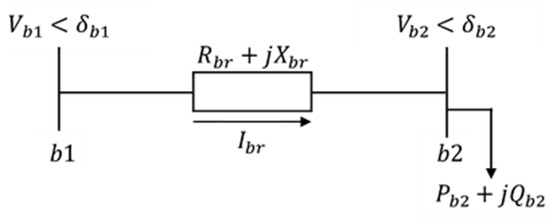
Figure 2.
Single-line diagram of two-bus distribution network.
Equations (4) and (5) can be used to compute power losses encountered across each distribution system’s branch, whereas Equation (6) can be used to calculate the amount of power dissipated over the entire distribution system.
where is the distribution network’s total loss, including both active and reactive power losses, and represents the total number of buses in the distribution network.
The power flow for the radial distribution networks incorporated with DG–capacitor units in Figure 3 can be computed using Equations (7) and (8). The active and reactive power flows at the terminal node of the branch can be mathematically stated as
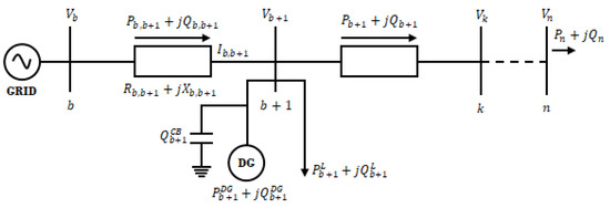
Figure 3.
Radial distribution system with DG and capacitor banks equipped on a bus.
Since the resistance to reactance ratio in distribution networks is so high, active power losses dominate in these networks. For this reason, the active power loss minimization is chosen as a first objective for this study rather than the total loss function. In a distribution network, the branch connecting buses and results in a power loss that can be computed as given in Equation (9).
The current flow through that branch (between buses b and b + 1) can be calculated as Equation (10).
The cumulative real power loss of distribution system is the sum of power losses across branches of the distribution network, as shown in Equation (11).
The mathematical expression of the first objective of the considered optimization problem minimizing the power loss function is presented in Equation (12).
2.2. Accessible Generation Capacity’s Utilization
In the event of a grid failure, DGs can fulfill the distribution network’s energy needs. The deployed capacitors can aid DGs in fulfilling the reactive power demand of load. Since the installed power-generating capacity of the DGs and capacitors is typically less than the load demand, the electricity injected into the autonomous distribution network is less than the energy needs. In this instance, the electric utility can address the supply–demand disparity by lowering the electricity consumption, shedding the load, or executing a demand-side management (DSM) scheme.
However, it is critical to figure out how much of the network’s load share can be supplied with the available DG and capacitor powers to employ any of these solutions. The problem is to find out how the installed DG and capacitor units can be used so as to maximize the supplied load share during islanded distribution network operation.
Power-generating sources generally operate at high power factors to minimize power losses and optimize the distribution networks’ utilization capacity. Furthermore, the utilization factor of the DGs, which is the ratio of the device’s actual output to the maximum achievable output (or rated capacity), can alter significantly as the operational power factor varies. However, the amount of active and reactive power generated is usually determined by the load. To put it in another way, the load on the distribution network should be assigned a quantity that allows the coupled DGs and capacitors to run at the required power factor and serve the maximum amount of energy to the load with minimal system losses. Therefore, the second minimization function chosen for this study is the under-utilization of accessible power generation, which evaluates whether or not a resource is being used to its maximum potential. The proposed objective function’s mathematical formulation is given in Equations (13)–(18).
where is the function of , which can be computed as Equation (15):
The values of and at any value of source power factor can be calculated as Equations (16) and (17), respectively.
Here the Sunder-utilization value might be anywhere between 0 and Savailable. A value of 0 for Sunder-utilization implies that the installed DGs/capacitors are fully operational. In contrast, Sunder-utilization > 0 indicates that the DGs–capacitors’ power is less than their installed capacity. As a result, the mathematical description of the proposed multi-criteria optimization problem is given as Equation (18) using a weighted sum approach:
2.3. Constraints
To evade undesired results in the proposed optimization problem, some constraints are imposed that must be satisfied in order to solve the problem successfully. As there is no power supply from the central grid during the islanded operation of the distribution network, only the mounted DGs and capacitors are responsible for meeting the load’s energy requirements. Since the installed units’ power output often is less than the load requirement, the first constraint posed for the islanded distribution network is the maximum active and reactive power flows across the network that must be equal to or less than the installed generation capacity of the installed DG and capacitor units (Equations (19) and (20)). In addition, each bus in the distribution network must have a voltage () that should be within 5% of the rated voltage () (Equation (21)). The assumed for this study is 1 p.u.
2.4. Decision Variables
For the studied optimization problem, the chosen decision (design) variable is the power factor of the DG–capacitor combination (pfsource) at which they are functioning. The upper and lower bounds set for pfsource are 0.8 and 0.93, respectively.
2.5. Modeling of DGs’ Power Output
For this study, the DGs’ power output is assumed as deterministic. The literature has classified the DGs into four types. Type 1 DG can inject only active power, including solar photovoltaic panels, fuel cells, and battery energy storage. DGs of type 2 only supply reactive power either using capacitors or D-STATCOM. Type 3 DG usually involves the synchronous generator, which can generate both active and reactive powers. Finally, type 4 DG includes an induction generator that can generate active power while absorbing the reactive power. This study assumes a type 1 DG, such as photovoltaic panels paired with batteries, to generate controlled active power output.
2.6. Modeling of Capacitors’ Power Output
Capacitor banks are devices that produce reactive power. They are currently available in the markets as fixed discrete types. Therefore, this paper considers the capacitors of discrete size for the optimal simultaneous allocation of capacitor and DG units in the distribution system. The capacitors available in the market are smaller units (50 kVAR), which are further integer multiples of factor k. Hence, the required amount of capacitor size can be determined using Equation (22).
where is an integer. The required amount of kVAR can be assessed such as [, 2, 3,…, ].
3. Proposed Methodological Framework to Optimize the Autonomous Network’s Operation
It is worth recalling that the distribution networks operate in grid-connected mode except when the grid has a fault or is being maintained. For this reason, the sizing and placement of capacitors and DGs must be chosen considering a grid-connected operation. Therefore, the first part of the proposed methodology is to obtain the optimal capacity and placement of the DGs and capacitors for grid-integrated distribution networks. In order to determine the optimal location and sizing for the DG and capacitor units, the Jaya algorithm (JA) was used. The JA, developed by Rao [51], is a stochastic heuristic optimization algorithm that only involves a single recombination step. In addition, the JA is different from most population-based optimization approaches as it uses no parameters, chosen by the user, in its execution. Only the maximum number of iterations (MaxItr) and population size (nPop) are to be specified for the JA [52,53]. In the recent literature, the efficiency of the JA has been demonstrated in various studies [54,55,56,57,58].
To mathematically describe the JA’s implementation cycle, let z be the real valued vector of decision variables composing one solution. The and indicate the best and worst so far solutions. The candidate’s jth decision variable in the iteration is represented as . Then, at the iteration, the numerical equation used to update the candidate solution is given as represented in Equation (23).
where and are random numbers selected with uniform probability between 0 and 1 at the kth iteration. The objective function value decides whether the updated solution can be preferred or not over the current solution .
The update procedure is repeated for each solution vector of the current population at iteration k. The outputs of all updates are the input population to the subsequent iteration. The termination conditions can be either a maximum number of iterations or a convergence to the desired outcome. The flowchart presented in Figure 4 elaborates the execution cycle of the JA.
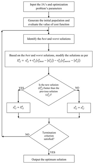
Figure 4.
Execution cycle of the Jaya algorithm.
Once the DGs and capacitors have been installed for the on-grid distribution network operation, replacing or relocating them for the short interval of the network’s autonomous operation is not viable. Hence, it is not feasible to repeatedly optimize the power-generating equipment’s size and location to enhance the functioning of distribution network under the autonomous operation mode. Therefore, this study considers the DG–capacitor combination’s power factor (pfsource) as the decision variable to achieve the desired goal of efficient and maximum utilization of the mounted devices under the distribution networks’ independent operation.
To evaluate the effect of pfsource on the autonomous distribution network’s functioning, a detailed framework is presented whose stepwise elaboration is explained as follows.
- Step 1.
- Define the base power, base voltage, load data, and line data for the selected distribution network.
- Step 2.
- Calculate the starting values of the objective functions, the active power loss in this case, by running the base case load flow for all the solutions of the starting population.
- Step 3.
- Set the JA’s parameters, nPop and MaxItr, and the parameters of the optimization problem, n (number of design variables) and Ud and Ld (upper and lower bounds).
- Step 4.
- Initialize the starting population with random values of the design variables.
- Step 5.
- Execute the power flow to compute the value of the objective function for each search agent of the starting population.
- Step 6.
- Find out the cost function values to determine the best and worst solutions.
- Step 7.
- Update the solutions of the current population, based on known best and worst solutions, as per Equation (23).
- Step 8.
- Carry out the power flow for each new solution vector and determine the cost function’s updated values.
- Step 9.
- Compare the new updated cost function values with the previous values for each solution. Adopt the new solution if it is superior to the old one; else, stick with the old solution. Create the new population replacing the old one.
- Step 10.
- Stop the optimization process if the maximum iteration count is completed. Otherwise, repeat steps 6 to 9. Finally, report the obtained final optimum solutions of DG–capacitor sizes and locations.
- Step 11.
- Disconnect the distribution network from the grid and identify the available maximum active and reactive power generations for the autonomous distribution network.
- Step 12.
- Specify a value for the DG–capacitor combination’s working power factor, (Equation (24)).
- Step 13.
- Gradually increase the active and reactive power demands of the load while keeping the source power factor constant at .Let Po,i, Qo,i be the initial active and reactive power demands of load connected at bus i, which are assumed as 50% of PDG,available and QCap,available.
Raise the load’s active and reactive power demands gradually, ΔPload,i and ΔQload,i, s.t. Equation (25) holds:
⇒ ∃ ΔPload,i and ΔQload,i:
where and are the active and reactive powers generated by the DG and capacitor, respectively.
- Step 14.
- Stop adding to the load demand, ifwhere is the voltage deviation at any bus b.
Output the values of and :
- Step 15.
- Compute the cost function value as Equation (18).
- Step 16.
- For the next value, repeat steps 12 to 15.
- Step 17.
- Compare the values of the cost function acquired at each and display the best solution value of .
A summary of the proposed methodological framework is presented in Figure 5.
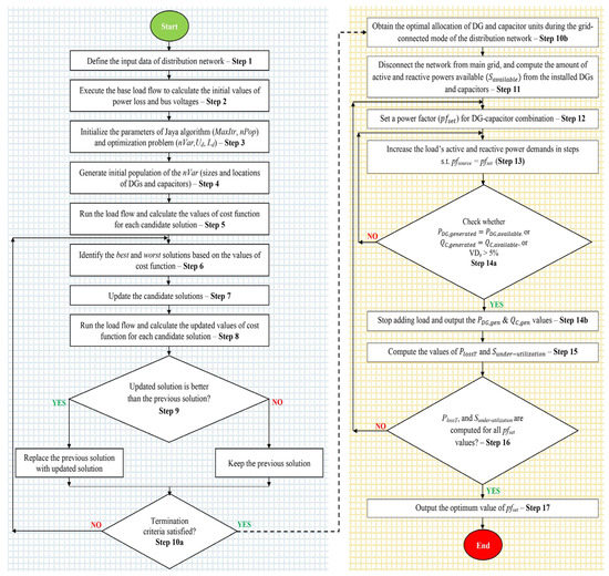
Figure 5.
The proposed methodology to efficiently utilize the mounted distributed sources in islanded distribution networks under the power mismatch condition.
4. Results and Discussion
For this study, the IEEE 33- and 69-bus networks were used to implement the proposed methodological framework. Due to their limited size, these test systems have been widely employed in the literature. The detailed data of the 33-bus and 69-bus test systems are provided in [40,59]. The value was calibrated between 0.8 and 0.93 to investigate the effect of the source power factor on the operation of the off-grid islanded distribution network. However, the comprehensive examination of the power factor effect has been provided for four specific cases, as follows:
- Case 1:
- DG–capacitor couple supplying power at a power factor of 0.93 (i.e., at the maximum bound).
- Case 1:
- DG–capacitor couple supplying power at (also termed as ).
- Case 3:
- DG–capacitor couple supplying power to the load at the load power factor ().
- Case 4:
- DG–capacitor couple supplying power at a power factor of 0.8 (i.e., at the minimum bound).
4.1. Optimal DG and Capacitor Unit Allocation for Grid-Integrated 33-Bus and 69-Bus Distribution Networks
The first part of the proposed methodology is to optimize the siting and sizing of active and reactive power sources in the grid-integrated distribution networks. The obtained results for the simultaneous DG–capacitor allotment in the 33-bus and 69-bus systems are presented in Table 2. After running JA 30 times, starting from randomly generated populations, the best optimal sizes and locations of the DG and capacitor units were determined and reported. In the 33-bus test system, the optimal allocations for the DG and capacitor units were found to be 2.54 MW at bus 6 and 1.26 MVAR at bus 30. Similarly, for the 69-bus test system, bus 61 was identified as the optimal location for both the DG and capacitor units, with a capacity of 1.8285 MW and 1.3 MVAR.
Table 2.
The results of simultaneous DG–capacitor allocation in 33-bus and 69-bus test systems.
The active power loss minimization (f1) is considered the primary objective function to attain the optimal DG and capacitor values (sizing and siting). The voltage magnitude at the network buses (Equation (21)) and the power flow limit through the wires (Equations (26) and (27)) are the non-equality and equality constraints posed for this optimization problem.
where are the sub-station’s active and reactive power supplies; is the DG’s active power injected into the distribution network; is the capacitor’s reactive injected into the distribution network; are the active and reactive power loads connected to each bus of the distribution network; and are the active and reactive power losses encountered across each network branch.
The four decision variables chosen for this complex optimization problem are DG size and location () and capacitor size and location (). These decision variables’ lower and upper bounds are set as and , except for bus 1 (i.e., the slack bus), DGs and capacitors can be located on any of the network buses, , and .
4.2. 33-Bus Autonomous Distribution Network
The 33-bus network’s total load is 4.369 MVA with a 0.85 power factor (), whereas the total power available from the mounted DG and capacitor is 2.835 MVA with a 0.896 power factor (). According to the data shown above, the available power of the attached DG and capacitor is 64.90 percent of the total need for electricity. It is important to note that the value is dependent on the mounted DG and capacitor units’ rated outputs; thus, it may differ accordingly. In the studies that focus solely on the optimal DG placement, the value will be defined by the stated optimal real and reactive power values produced by DG alone. The optimal allocation of the DG and capacitor units in the off-grid 33-bus islanded distribution network is shown in Figure 6.
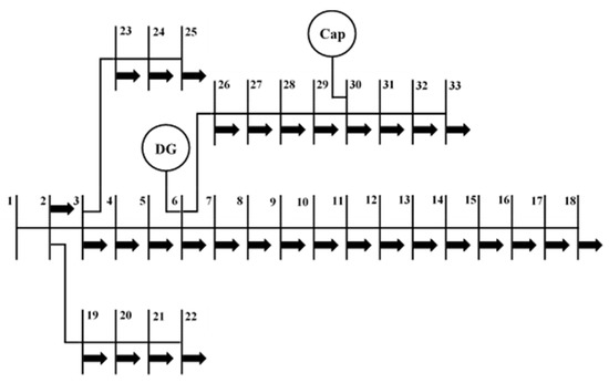
Figure 6.
The 33-bus autonomous network with mounted DGs.
In the first case, the DG and capacitor combination’s operating power factor is set to 0.93 . In this situation, the total load handled by the DG–capacitor pair is just 2.677 MVA or 61.27 percent of the distribution system’s entire load demand. The aggregate active power losses of 0.047 MW are reported under this situation, with bus 18 having the lowest bus voltage of 0.975 p.u. The DG and capacitor collectively produce 2.731 MVA power, which is 62.3 percent of the total power demand of the 33-bus network. As a result, assuming the installed DG and capacitor run at a power factor of 0.93, they can produce enough energy to meet 62.3 percent of the network’s total load in autonomous mode. The accessible generation capacity of 3.99 percent remains unutilized in this situation, whereas the operating efficiency evaluated in this case is 98.35 percent.
In case 2, the DG–capacitor combination’s operating power factor is set to 0.896, based on the installed units’ rated values (2.54 MW and 1.26 MVAR). The DG and capacitor operate at full capacity in this state, and no electricity generation is left over. The DG and the capacitor collectively carry 2.782 MVA of load, accounting for 63.68 percent of the total demand of the islanded network. With a minimum bus voltage of 0.974 p.u. obtained at bus 18, an active power loss of 0.045 MW is recorded in this case. The power output produced by the DG and capacitor in this scenario is 2.835 MVA or 64.90 percent of the total load. In this case, the network’s operating efficiency is assessed to be 98.13 percent, which is somewhat higher than in the prior case. In addition, in case 2, the power output obtained from the mounted power-generating units is higher.
In the third case, the was kept at 0.85, which was the same as . The load capacity collectively supplied by the DG and capacitor in this state is 2.352 MVA or 53.83 percent of the entire network load. In this circumstance, the power loss accounted in the islanded network is 0.034 MW, and bus 18 has the lowest voltage of 0.979 p.u. The total generated power is obtained as 2.392 MVA that is 54.75 percent of the 33-bus distribution network’s peak demand. As a result, 15.63 percent of the generation capacity is under-utilized, with an operating efficiency of 98.33 percent in this situation. However, unlike prior cases, the installed units offer less power that is marginally more than 50% of the whole power demand.
For the proposed case 4, the is tuned to the minimum 0.8 value that is lower than both and . In this circumstance, the combined load handled by the DG and capacitor is 2.067 MVA or 47.31 percent of the overall load. With a minimum voltage of 0.981 p.u., this arrangement produces a real power loss of 0.028 MW. Bus 18 observed the minimal bus voltage once again, just like in previous cases. The total electricity produced by the DG and capacitor, in this case, is 2.1 MVA, 48.07 percent of the total demand, and the network’s operating efficiency is 98.43 percent. It is the worst-case scenario among the four proposed cases, as the under-utilization of the power-generating devices reaches 25.93 percent, i.e., during the independent functioning of the distribution network, more than a quarter of the available power-producing capacity is left unused. Table 3 presents the statistical summary of the four cases examined; moreover, the graphical representation of the comparative analysis is provided in Figure 7 and Figure 8.
Table 3.
Results for the 33-bus autonomous distribution network.
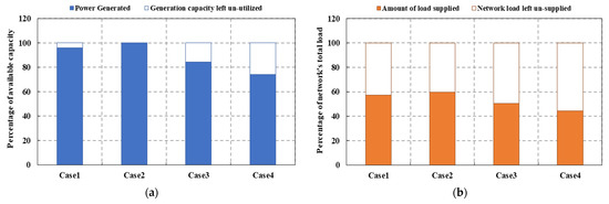
Figure 7.
Performance comparison of the 33-bus autonomous distribution network at different pfsource. (a) Installed power generation capacity’s % utilization and (b) network’s % load share delivered with accessible power.
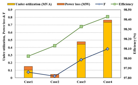
Figure 8.
The observed efficiency (%), under-utilization (MVA), power losses (MW), and objective function (F) values in four cases for 33-bus autonomous distribution network.
The findings illustrate that keeping the DG–capacitor combination’s power factor close to is the most efficient approach to operate the islanded distribution networks. The value can be computed from the DG and capacitor’s optimal ratings obtained during the grid-integrated network operation. At this power factor, both the DG and capacitor supply power to their full potentials. It can be seen from the results that the operating efficiency of the islanded distributed network achieved in cases 3 and 4 is marginally higher than that obtained in cases 1 and 2 because the mounted active and reactive power-generating components are not utilized to their full capability in the latter two cases. Therefore, the reduced power flows through the distribution lines cause a considerable reduction in power loss. While these cases have lower power losses than cases 1 and 2, the difference is insignificant compared with the additional power delivered by the mounted units in the first two cases. In addition to the distribution network’s operating efficiency, the impact of the DG–capacitor pair’s operational power factor on the voltage profile of the islanded distribution networks has also been analyzed, as shown in Figure 8. Since the distribution network is less loaded in cases 3 and 4 due to the opted values, the bus voltages attained for these cases show a modest enhancement. In four cases, the minimum bus voltages for the 33-bus islanded network were recorded at bus 18, ranging from 0.974 to 0.981. Despite the fact that the power grid was not feeding energy during the islanded operation, the bus voltages remained within the defined limits even when the mounted devices were fully loaded. This is owing to the optimum DG and capacitor positions attained during on-grid operation, with the DG located at the central position of bus 6 and the capacitor’s placement at bus 30 near the end point buses, which allows the voltage to be maintained within a set margin (i.e., ±5% of ) on the weakest buses. Furthermore, even though the installed power-generating units can carry more load, the proposed strategic approach’s operating mechanism prevents the islanded network from being loaded beyond the limit that drops the voltage below the predefined margin, as specified in step 14 of Section 3. For this reason, the end buses (buses 18, 25, and 33) have voltages that are well within the operational limits, as seen in Figure 9.
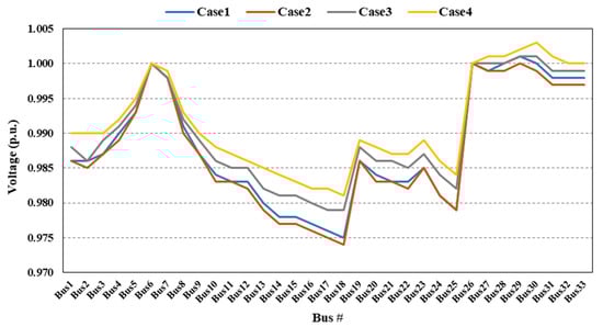
Figure 9.
Voltage profiles of the 33-bus autonomous distribution network attained in each case.
4.3. 69-Bus Autonomous Distribution Network
For the 69-bus distribution network, the optimal siting and sizing of the single DG and single capacitor units determined during the grid-integrated mode using JA were 1.8285 MW (at bus 61) and 1.3 MVAR (at bus 61), respectively. Hence, the total accessible electricity from the mounted distributed resources is 2.244 MVA with a power factor of 0.815 (). The optimal allocation of the distributed active–reactive power units in the 69-bus autonomous distribution network is shown in Figure 10. The IEEE 69-bus radial distribution network’s active power load is 3.80219 MW, and the reactive power load is j2.6946 MVAR (total 4.66 MVA) with a of 0.816. The computed percentage of the power generation share is 48.15% of the total demand from the presented DG and capacitor values. To examine how this accessible power can be utilized to the maximum potential, the studied four power factor values for the 69-bus network are 0.93, 0.815 (pfsource), 0.816 (pfload), and 0.8. It must be noted that unlike the 33-bus distribution network, the pfsource value for the 69-bus network is less than the pfload. Here the pfsource value is close to the minimum bound of the opted range of power factors, i.e., 0.8. For the 33-bus network, the pfsource value was close to the upper limit (0.93) of the selected range of the operating power factors. Hence, the 69-bus distribution network’s power factor values also offer the sensitivity analysis of the proposed methodology for the autonomous distribution networks by examining their performance under uncertain input conditions. The quantities measured for the 69-bus distribution system are presented in Table 4.
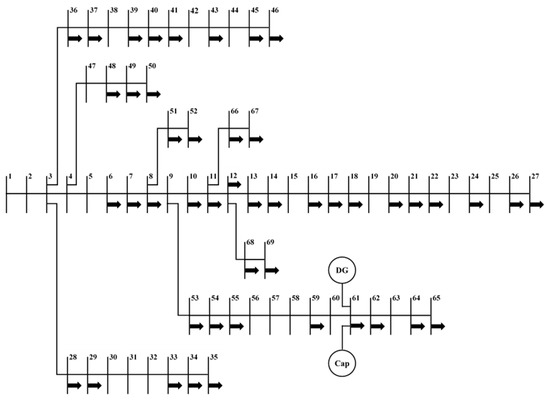
Figure 10.
The 69-bus autonomous distribution network with installed distributed sources.
Table 4.
Results for the 69-bus autonomous distribution network.
For the 69-bus autonomous network, although the DG–capacitor pair’s operating rated power factor is low, the results revealed that the installed devices produce maximum power when operating at or close to the rated pfsource. Dissimilar to the 33-bus network, where the minimum power generation was observed in case4, the minimum amount of generated power is acquired in case 1 when the mounted DG and capacitor were generating power at the 0.93 pfsource (Figure 11). This clearly shows that the best power factor for the autonomous distribution networks lies close to the pfsource. Any other power factor farther from this range will cause a significant dip in the under-utilization of the mounted devices’ power-generating potential.
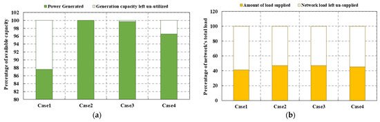
Figure 11.
Performance comparison of the 69-bus autonomous distribution network at different pfsource. (a) Installed power generation capacity’s percent utilization. (b) Network’s percent load share delivered with accessible power.
Conversely, for the 33-bus and 69-bus independent distribution networks, the highest power losses were produced at the power factors close to the pfsource. Undoubtedly, this is because of the maximum power that flows at the pfsource values. The graphical illustration of the obtained results in the studied four cases for the 69-bus autonomous distribution network is presented in Figure 12. In addition, the graphical illustration of the network’s voltage profiles obtained in four cases is presented in Figure 13. The voltage profiles show that the voltages at bus 61 and neighboring buses lie close to the rated value of 1 p.u., which are due to the DG and capacitor units’ allocation at bus 61. In addition, because of the tactically placed DG–capacitor modules and proposed mechanism of the methodological framework, the voltage profiles lie within acceptable bounds in all cases, even if the DG–capacitor operates to its full capacity. Unlike the 33-bus distribution network, where the lowest voltage value was observed at a single bus, the minimum bus voltages for the 69-bus islanded network were observed across several buses (from bus 17 to bus 27), ranging from 0.954 to 0.958 in four cases.
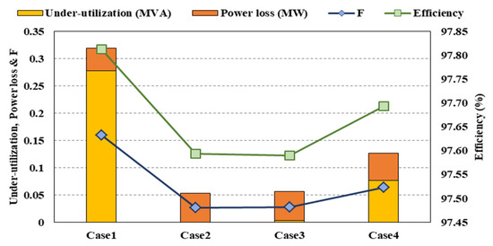
Figure 12.
The observed efficiency (%), under-utilization (MVA), power losses (MW), and function F values in four cases for the 69-bus autonomous distribution network.
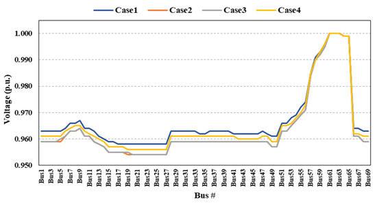
Figure 13.
Voltage profiles of autonomous 69-bus distribution network.
5. Conclusions and Future Work
This paper introduces a strategic planning methodology for the efficient utilization of installed distributed generation units in distribution networks’ during their islanded operation, due to a fault. Unlike the existing studies, the event of power supply–demand mismatch has been considered to analyze the extent to which the energy needs of the islanded network can be fulfilled by mounting dispersed power-generating units.
A multi-criterion bi-objective function has been developed, including minimization objectives of active power loss reduction and decrement in accessible power generation’s under-utilization.
Four cases were devised to see how much of the available DG-capacitor capacity was under-utilized at the different operational power factor values of the DG-capacitor combination.
The study found that the non-utilization of available power generation capacity in the 33-bus distribution network can vary by up to 25.93% across power factors ranging from 0.8 to 0.93. Similarly, the under-utilization in the 69-bus distribution network can deviate up to 12.23%. Furthermore, the obtained results show that deployed DGs and capacitors operating at a source power factor (i.e., power factor incurred from their optimal capacities) can meet the energy requirements of a larger portion of the network load.
This is because the load demand handled by DGs and capacitors is less than the highest possible share at any other power factor. Conversely, operating the DG-capacitor combination close to the source power factor causes an increase in power loss. However, compared with the increased load served with the available generation, the increase in power loss is negligible.
The efficient employment of the active and reactive power sources in autonomous mode during power deficit events necessitates developing effective demand-side management (DSM) schemes for the electrical power systems. The establishment of any such comprehensive plan is beyond the scope of this study. However, this research will pave the way for such future investigations. Henceforward, the proposed methodological framework can also be applied to different DGs, evaluating the uncertainties of power generation.
Author Contributions
Conceptualization, Z.H.L., M.Y.H. and D.M.S.; data curation, Z.H.L., M.Y.H., D.M.S. and L.K.; writing—original draft preparation, Z.H.L., M.Y.H., D.M.S., M.K., Q.T.T. and E.R.S.; writing—review and editing, Z.H.L., M.Y.H., D.M.S., M.K., Q.T.T. and E.R.S.; supervision, M.Y.H. and D.M.S. All authors have read and agreed to the published version of the manuscript.
Funding
This research received no external funding.
Data Availability Statement
Data is contained within the article in the form of results provided in tables. No new data were created or analyzed in this study. Therefore, data sharing is not applicable to this article.
Acknowledgments
The first author wishes to express his gratitude to the HEC (Higher Education Commission), Pakistan, and MUET (Mehran University of Engineering & Technology), Jamshoro, Sindh, Pakistan, for providing financial assistance in pursuing higher education. Furthermore, all authors wish to extend their appreciation to the UTM (Universiti Teknologi Malaysia) for its technical services.
Conflicts of Interest
The authors declare no conflict of interest.
References
- Gholami, R.; Shahabi, M.; Haghifam, M. An efficient optimal capacitor allocation in DG embedded distribution networks with islanding operation capability of micro-grid using a new genetic based algorithm. Int. J. Electr. Power Energy Syst. 2015, 71, 335–343. [Google Scholar] [CrossRef]
- Wang, M.; Zhong, J. A novel method for distributed generation and capacitor optimal placement considering voltage profiles. In Proceedings of the 2011 IEEE Power and Energy Society General Meeting, Detroit, MI, USA, 24–28 July 2011; pp. 1–6. [Google Scholar]
- Yazdavar, A.H.; Shaaban, M.F.; El-Saadany, E.F.; Salama, M.M.A.; Zeineldin, H.H. Optimal planning of distributed generators and shunt capacitors in isolated microgrids with nonlinear loads. IEEE Trans. Sustain. Energy 2020, 11, 2732–2744. [Google Scholar] [CrossRef]
- Kirthiga, M.V.; Daniel, S.A.; Gurunathan, S. A methodology for transforming an existing distribution network into a sustainable autonomous micro-grid. IEEE Trans. Sustain. Energy 2013, 4, 31–41. [Google Scholar] [CrossRef]
- Anand, M.P.; Ongsakul, W.; Singh, J.G.; Sudhesh, K.M. Optimal allocation and sizing of distributed generators in autonomous microgrids based on LSF and PSO. In Proceedings of the 2015 International Conference on Energy Economics and Environment (ICEEE), Greater Noida, India, 27–28 March 2015; pp. 1–6. [Google Scholar]
- Jamian, J.J.; Mustafa, M.W.; Mokhlis, H.; Baharudin, M.A.; Abdilahi, A.M. Gravitational search algorithm for optimal distributed generation operation in autonomous network. Arab. J. Sci. Eng. 2014, 39, 7183–7188. [Google Scholar] [CrossRef]
- Farag, H.E.Z.; El-Saadany, E.F. Optimum shunt capacitor placement in multimicrogrid systems with consideration of islanded mode of operation. IEEE Trans. Sustain. Energy 2015, 6, 1435–1446. [Google Scholar] [CrossRef]
- Leghari, Z.H.; Kumar, M.; Shaikh, P.H.; Kumar, L.; Tran, Q.T. A Critical Review of Optimization Strategies for Simultaneous Integration of Distributed Generation and Capacitor Banks in Power Distribution Networks. Energies. 2022, 15, 8258. [Google Scholar] [CrossRef]
- Vita, V.; Fotis, G.; Pavlatos, C.; Mladenov, V. A New Restoration Strategy in Microgrids after a Blackout with Priority in Critical Loads. Sustainability 2023, 15, 1974. [Google Scholar] [CrossRef]
- Fotis, G.; Vita, V.; Maris, T.I. Risks in the European Transmission System and a Novel Restoration Strategy for a Power System after a Major Blackout. Appl. Sci. 2023, 13, 83. [Google Scholar] [CrossRef]
- Eid, A. Cost-based analysis and optimization of distributed generations and shunt capacitors incorporated into distribution systems with nonlinear demand modeling. Expert Syst. Appl. 2022, 198, 116844. [Google Scholar] [CrossRef]
- Mouwafi, M.T.; El-sehiemy, R.A.; El-ela, A.A.A. A two-stage method for optimal placement of distributed generation units and capacitors in distribution systems. Appl. Energy 2022, 307, 118188. [Google Scholar] [CrossRef]
- Leghari, Z.H.; Hussain, S.; Memon, A.; Memon, A.H.; Baloch, A.A. Parameter-Free Improved Best-Worst Optimizers and Their Application for Simultaneous Distributed Generation and Shunt Capacitors Allocation in Distribution Networks. Int. Trans. Electr. Energy Syst. 2022, 2022, 1–31. [Google Scholar] [CrossRef]
- Naderipour, A.; Malek, Z.A.; Hajivand, M. Spotted hyena optimizer algorithm for capacitor allocation in radial distribution system with distributed generation and microgrid operation considering different load types. Sci. Rep. 2021, 11, 2728. [Google Scholar] [CrossRef] [PubMed]
- Malik, M.Z.; Kumar, M.; Soomro, A.M.; Baloch, M.; Gul, M.; Farhan, M.; Kaloi, G.S. Strategic planning of renewable distributed generation in radial distribution system using advanced MOPSO method. Energy Rep. 2020, 6, 2872–2886. [Google Scholar] [CrossRef]
- Tolabi, H.B.; Ara, A.L.; Hosseini, R. A new thief and police algorithm and its application in simultaneous reconfiguration with optimal allocation of capacitor and distributed generation units. Energy 2020, 203, 117911. [Google Scholar] [CrossRef]
- Almabsout, E.; El-Sehiemy, R.; An, O.; Bayat, O. A hybrid local search-genetic algorithm for simultaneous placement of DG units and shunt capacitors in radial distribution systems. IEEE Access 2020, 8, 54465–54481. [Google Scholar] [CrossRef]
- Manikanta, G.; Mani, A.; Singh, H.P.; Chaturvedi, D.K. Simultaneous placement and sizing of DG and capacitor to minimize the power losses in radial distribution network. In Soft Computing: Theories and Applications; Springer: Berlin/Heidelberg, Germany, 2019; pp. 605–618. [Google Scholar]
- Sambaiah, K.S.; Jayabarathi, T. Optimal allocation of renewable distributed generation and capacitor banks in distribution systems using salp swarm algorithm. Int. J. Renew. Energy Res. 2019, 9, 96–107. [Google Scholar]
- Lotfi, H.; Elmi, M.B.; Saghravanian, S. Simultaneous placement of capacitor and DG in distribution networks using particle swarm optimization algorithm. Int. J. Smart Electr. Eng. 2018, 7, 35–41. [Google Scholar]
- Mehmood, K.K.; Kim, C.-H.; Khan, S.U.; Haider, Z. Unified Planning of Wind Generators and Switched Capacitor Banks: A Multiagent Clustering-Based Distributed Approach. IEEE Trans. Power Syst. 2018, 33, 6978–6988. [Google Scholar] [CrossRef]
- Dixit, M.; Kundu, P.; Jariwala, H.R. Incorporation of distributed generation and shunt capacitor in radial distribution system for techno-economic benefits. Eng. Sci. Technol. Int. J. 2017, 20, 482–493. [Google Scholar] [CrossRef]
- Biswas, P.P.; Mallipeddi, R.; Suganthan, P.N.; Amaratunga, G.A.J. A multiobjective approach for optimal placement and sizing of distributed generators and capacitors in distribution network. Appl. Soft Comput. J. 2017, 60, 268–280. [Google Scholar] [CrossRef]
- Ghanegaonkar, S.P.; Pande, V.N. Optimal hourly scheduling of distributed generation and capacitors for minimisation of energy loss and reduction in capacitors switching operations. IET Gener. Transm. Distrib. 2017, 11, 2244–2250. [Google Scholar] [CrossRef]
- Mahesh, K.; Nallagownden, P.; Elamvazuthi, I. Optimal placement and sizing of renewable distributed generations and capacitor banks into radial distribution systems. Energies 2017, 10, 1–24. [Google Scholar]
- Muthukumar, K.; Jayalalitha, S. Integrated approach of network reconfiguration with distributed generation and shunt capacitors placement for power loss minimization in radial distribution networks. Appl. Soft Comput. J. 2017, 52, 1262–1284. [Google Scholar]
- Khodabakhshian, A.; Andishgar, M.H. Simultaneous placement and sizing of DGs and shunt capacitors in distribution systems by using IMDE algorithm. Int. J. Electr. Power Energy Syst. 2016, 82, 599–607. [Google Scholar] [CrossRef]
- Jannat, M.B.; Savić, A.S. Optimal capacitor placement in distribution networks regarding uncertainty in active power load and distributed generation units production. IET Gener. Transm. Distrib. 2016, 10, 3060–3067. [Google Scholar] [CrossRef]
- Lalitha, M.P.; Babu, P.S.; Adivesh, B. Optimal distributed generation and capacitor placement for loss minimization and voltage profile improvement using symbiotic organisms search algorithm. Int. J. Electr. Eng. 2016, 9, 249–261. [Google Scholar]
- Rahmani-Andebili, M. Simultaneous placement of DG and capacitor in distribution network. Electr. Power Syst. Res. 2016, 131, 1–10. [Google Scholar] [CrossRef]
- Ghaffarzadeh, N.; Sadeghi, H. A new efficient BBO based method for simultaneous placement of inverter-based DG units and capacitors considering harmonic limits. Int. J. Electr. Power Energy Syst. 2016, 80, 37–45. [Google Scholar] [CrossRef]
- Pereira, B.R.; Martins Da Costa, G.R.M.; Contreras, J.; Mantovani, J.R.S. Optimal distributed generation and reactive power allocation in electrical distribution systems. IEEE Trans. Sustain. Energy 2016, 7, 975–984. [Google Scholar] [CrossRef]
- Kayal, P.; Chanda, C.K. Strategic approach for reinforcement of intermittent renewable energy sources and capacitor bank for sustainable electric power distribution system. Int. J. Electr. Power Energy Syst. 2016, 83, 335–351. [Google Scholar] [CrossRef]
- Khan, N.; Ghoshal, S.; Ghosh, S. Optimal allocation of distributed generation and shunt capacitors for the reduction of total voltage deviation and total line loss in radial distribution systems using binary collective animal behavior optimization algorithm. Electr. Power Compon. Syst. 2015, 43, 119–133. [Google Scholar] [CrossRef]
- Zeinalzadeh, A.; Mohammadi, Y.; Moradi, M.H. Optimal multi objective placement and sizing of multiple DGs and shunt capacitor banks simultaneously considering load uncertainty via MOPSO approach. Int. J. Electr. Power Energy Syst. 2015, 67, 336–349. [Google Scholar] [CrossRef]
- Jain, N.; Singh, S.; Srivastava, S. PSO based placement of multiple wind DGs and capacitors utilizing probabilistic load flow model. Swarm Evol. Comput. 2014, 19, 15–24. [Google Scholar] [CrossRef]
- Mahari, A.; Mahari, A. Optimal DG and capacitor allocation in distribution systems using DICA. J. Eng. Sci. Technol. 2014, 9, 641–656. [Google Scholar]
- Syed, M.S.; Injeti, S. Simultaneous optimal placement of DGs and fixed capacitor banks in radial distribution systems using BSA optimization. Int. J. Comput. Appl. 2014, 108, 28–35. [Google Scholar]
- Hosseinzadehdehkordi, R.; Nasab, M.E.; Hossein, S.; Karimi, M.; Farhadi, P. Optimal sizing and siting of shunt capacitor banks by a new improved differential evolutionary algorithm. Int. Trans. Electr. Energy Syst. 2013, 24, 1089–1102. [Google Scholar] [CrossRef]
- Aman, M.M.; Jasmon, G.B.; Solangi, K.H.; Bakar, A.H.A.; Mokhlis, H. Optimum simultaneous DG and capacitor placement on the basis of minimization of power losses. Int. J. Comput. Electr. Eng. 2013, 5, 516–522. [Google Scholar] [CrossRef]
- Musa, I.; Zahawi, B.; Gadoue, S.M. Integration of induction generator based distributed generation and shunt compensation capacitors in power distribution networks. In Proceedings of the 4th International Conference on Power Engineering, Energy and Electrical Drives, Istanbul, Turkey, 13–17 May 2013; pp. 1105–1109. [Google Scholar]
- Manafi, H.; Ghadimi, N.; Ojaroudi, M.; Farhadi, P. Optimal Placement of Distributed Generations in Radial Distribution Systems Using Various PSO and DE Algorithms. Electron. Electr. Eng. 2013, 19, 53–57. [Google Scholar] [CrossRef]
- Karimi, M.; Shayeghi, H.; Banki, T.; Farhadi, P.; Ghadimi, N. Solving optimal capacitor allocation problem using DE algorithm in practical distribution networks. Prz. Elektrotechniczny 2012, 88, 90–93. [Google Scholar]
- Zou, K.; Agalgaonkar, A.P.; Muttaqi, K.M.; Perera, S. Voltage support by distributed generation units and shunt capacitors in distribution systems. In Proceedings of the 2009 IEEE Power & Energy Society General Meeting, Calgary, AB, Canada, 26–30 July 2009; pp. 1–8. [Google Scholar]
- Zou, K.; Agalgaonkar, A.; Muttaqi, K.; Perera, S. Optimisation of Distributed Generation Units and shunt capacitors for economic operation of distribution systems. In Proceedings of the2008 Australasian Universities Power Engineering Conference, Sydney, NSW, Australia, 14–17 December 2008; pp. 1–7. [Google Scholar]
- Sultana, S.; Roy, P.K. Optimal capacitor placement in radial distribution systems using teaching learning based optimization. Int. J. Electr. Power Energy Syst. 2014, 54, 387–398. [Google Scholar] [CrossRef]
- Rashtchi, V.; Darabian, M.; Molaei, S. A robust technique for optimal placement of distribution generation. In Proceedings of the International Conference on Advanced Computer Science, Information Technology, Electronics Engineering & Communication, Hangzhou, China, 23–25 March 2012; pp. 31–35. [Google Scholar]
- Nekooei, K.; Farsangi, M.M.; Nezamabadi-pour, H.; Lee, K. An improved multi-objective harmony search for optimal placement of DGs in distribution systems. IEEE Trans. Smart Grid 2013, 4, 557–567. [Google Scholar] [CrossRef]
- Nojavan, S.; Jalali, M.; Zare, K. Optimal allocation of capacitors in radial/mesh distribution systems using mixed integer nonlinear programming approach. Electr. Power Syst. Res. 2014, 107, 119–124. [Google Scholar] [CrossRef]
- Singh, H.; Hao, S.A. Papalexopoulos, Transmission congestion management in competitive electricity markets. IEEE Trans. Power Syst. 1998, 13, 672–680. [Google Scholar] [CrossRef]
- Rao, R.V. Jaya: A simple and new optimization algorithm for solving constrained and unconstrained optimization problems. Int. J. Ind. Eng. Comput. 2016, 7, 19–34. [Google Scholar]
- Demircali, A.; Koroglu, S. Jaya algorithm-based energy management system for battery- and ultracapacitor-powered ultralight electric vehicle. Int. J. Energy Res. 2020, 44, 4977–4985. [Google Scholar] [CrossRef]
- Leghari, Z.H.; Hassan, M.; Said, D.; Memon, Z.A.; Hussain, S. An efficient framework for integrating distributed generation and capacitor units for simultaneous grid- connected and islanded network operations. Int. J. Energy Res. 2021, 45, 1–39. [Google Scholar] [CrossRef]
- Jumani, T.A.; Mustafa, M.W.; Hussain, Z.; Rasid, M.M.; Saeed, M.S.; Memon, M.M.; Khan, K.S. Nisar, Jaya optimization algorithm for transient response and stability enhancement of a fractional-order PID based automatic voltage regulator system. Alexandria Eng. J. 2020, 59, 2429–2440. [Google Scholar] [CrossRef]
- Abhishek, K.; Kumar, V.R.; Datta, S.; Mahapatra, S. Application of Jaya algorithm for the optimization of machining performance characteristics during the turning of CFRP (epoxy) composites: Comparison with TLBO, GA, and ICA. Eng. Comput. 2017, 33, 457–475. [Google Scholar] [CrossRef]
- Du, D.C.; Vinh, H.H.; Trung, V.D.; Hong Quyen, N.T.; Trung, N.T. Efficiency of Jaya algorithm for solving the optimization-based structural damage identification problem based on a hybrid objective function. Eng. Optim. 2018, 50, 1233–1251. [Google Scholar] [CrossRef]
- Rao, R.; Saroj, A. Economic optimization of shell-and-tube heat exchanger using Jaya algorithm with maintenance consideration. Appl. Therm. Eng. 2017, 116, 473–487. [Google Scholar] [CrossRef]
- Jin, R.V.; Wang, L.; Huang, C.; Jiang, S. Wind turbine generation performance monitoring with Jaya algorithm. Int. J. Energy Res. 2019, 43, 1604–1611. [Google Scholar] [CrossRef]
- Aman, M.M.; Jasmon, G.B.; Bakar, A.H.A.; Mokhlis, H. Optimum network reconfiguration based on maximization of system loadability using continuation power flow theorem. Int. J. Electr. Power Energy Syst. 2014, 54, 123–133. [Google Scholar] [CrossRef]


Disclaimer/Publisher’s Note: The statements, opinions and data contained in all publications are solely those of the individual author(s) and contributor(s) and not of MDPI and/or the editor(s). MDPI and/or the editor(s) disclaim responsibility for any injury to people or property resulting from any ideas, methods, instructions or products referred to in the content. |
© 2023 by the authors. Licensee MDPI, Basel, Switzerland. This article is an open access article distributed under the terms and conditions of the Creative Commons Attribution (CC BY) license (https://creativecommons.org/licenses/by/4.0/).