
State of the Art in Designing Fish-Friendly Turbines: Concepts and Performance Indicators


Abstract
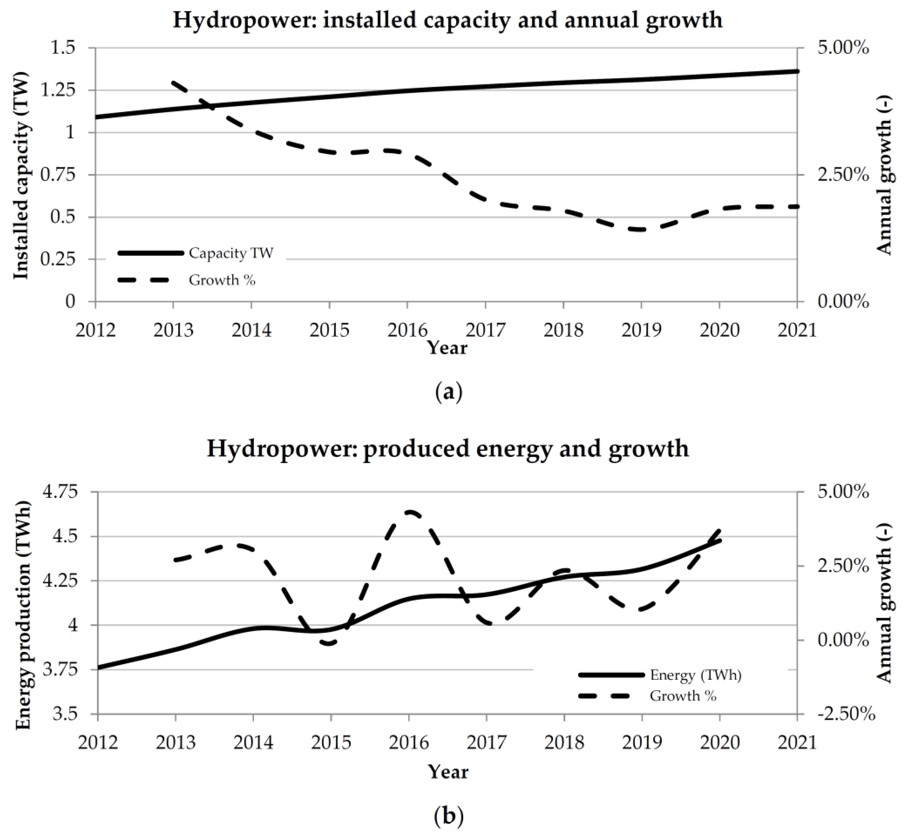
:1. Introduction
- -
- The direct destruction of fauna and flora habitats, by changing the use of land and by submerging large areas, to achieve the formation of a reservoir;
- -
- Indirect disturbance to local life, due to building infrastructure (e.g., roads, electrical grid, etc.) and gaining access to previously inaccessible areas. This can also involve induced disturbance due to population living in the reservoir area being resettled to formerly natural areas;
- -
- Disruption of the natural flow of a water stream, by forming a reservoir. Inherently, the construction of any sort of dam implies a partial or total impedance of free migration of aquatic species, the blocking of sediments that would replenish downstream ecosystems and the change in the downstream flow patterns of the river.
- -
- Artificial fishways incorporate artificial flow reduction elements such as baffles (also known as Denil fishways) or steps (e.g., pool-and-weir, vertical-slot fishways or fish-ladders, see Figure 3a,b, respectively);
- -
- Nature-like fishways contain natural features that increase bottom roughness such as cobble and boulders (see, e.g., Figure 4a), although they may incorporate some engineered elements such as anchored concrete blocks or other artificial elements that may be found in technical fishways.
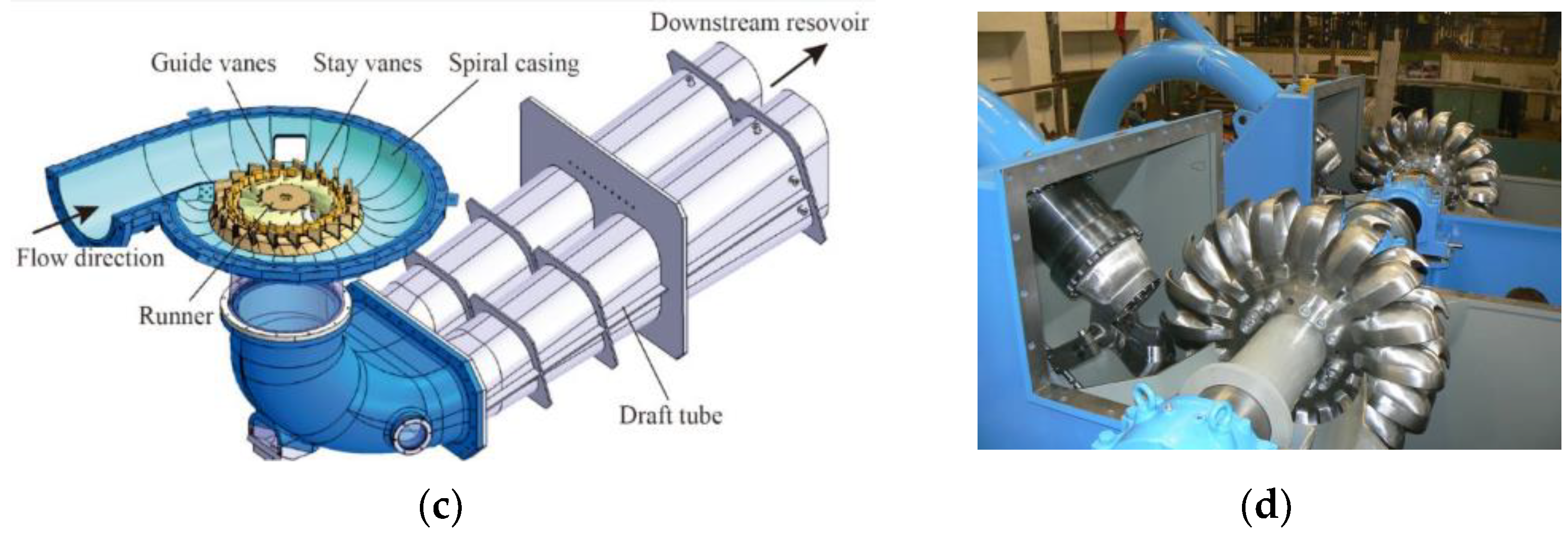
2. Structure of Hydropower Station

3. Mechanisms of Fish Damage and Mortality during Passage through a Turbine
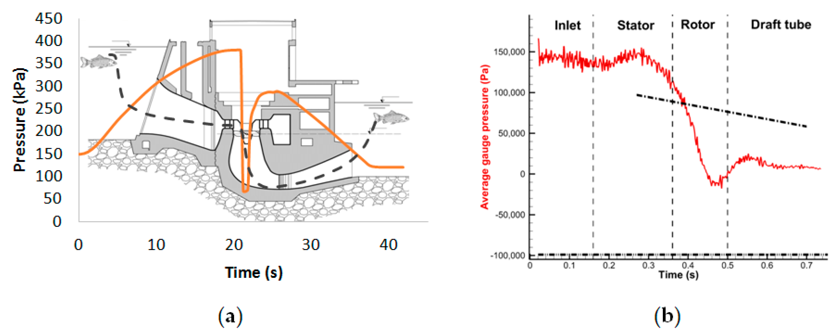
3.1. Pressure Changes
3.2. Mechanical Damage
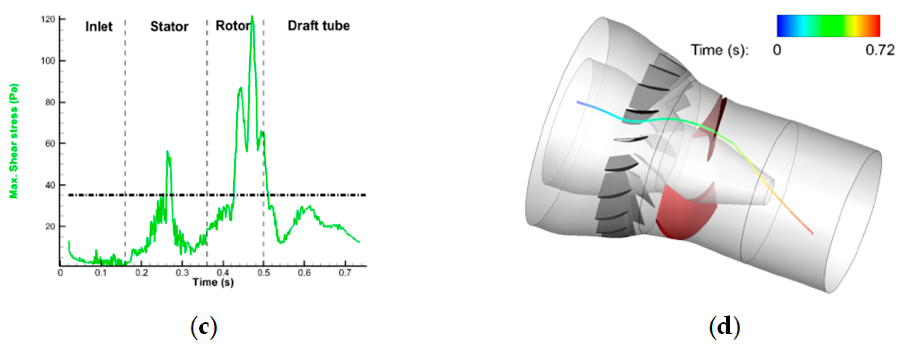
3.3. Shear Stresses
3.4. Vorticity and Turbulence
4. Assessing Fish Damage
4.1. Experimental Methods
4.2. Assessing Fish Damage—Numerical Methods
4.2.1. Early Attempts
4.2.2. Particle-Based Methods
4.2.3. Fully Coupled 6-Degrees-of-Freedom (6-DoF); Overset Meshes
4.2.4. Fully Coupled 6-Degrees-of-Freedom (6-DoF); Immersed Boundaries
4.2.5. Uncoupled 6-Degrees-of-Freedom (6-DoF)
4.2.6. Summary of Computational Methods
5. Derivation of Indices/Metrics to Assess the Fish-Friendliness of Hydro-Turbines
6. Fish-Friendly Hydropower Design Concepts
- -
- -
- Low rotational speed of the turbine runner;
- -
- Large passages;
- -
- Few blades;
- -
- No exposed gaps.
- -
- Oxygen deficiency in the water of reservoirs of hydropower plants, which can cause damage to downstream ecosystems. Hence, artificial aeration of the flowing water is a consideration that needs to be taken into account for successful fish-friendly turbines [129];
- -
- Oil leaks; oil is used both as a means of lubrication and as a means of actuation of turbine blades (e.g., in the case of Kaplan turbines). To date, several Kaplan–Bulb and Francis turbines have been upgraded so as to make them work free from oil, and new materials and lubricants are being developed.
7. Conclusions and Future Perspectives
Author Contributions
Funding

Data Availability Statement
Conflicts of Interest
References
- BP p.l.c. Bp Statistical Review of World Energy; BP Plc: London, UK, 2022. [Google Scholar]
- IRENA. Renewable Energy Statistics 2022; International Renewable Energy Agency: Abu Dhabi, United Arab Emirates, 2022. [Google Scholar]
- International Energy Agency. Hydropower; International Energy Agency: Paris, France, 2021.
- Jager, H.I.; De Silva, T.; Uria-Martinez, R.; Pracheil, B.M.; Macknick, J. Shifts in Hydropower Operation to Balance Wind and Solar Will Modify Effects on Aquatic Biota. Water Biol. Secur. 2022, 1, 100060. [Google Scholar] [CrossRef]
- Murdock, H.; Duncan, G.; Thomas, A. Renewables Global Status Report; International Nuclear Information System: Vienna, Austria, 2021. [Google Scholar]
- International Energy Agency. How Rapidly Will the Global Electricity Storage Market Grow by 2026? International Energy Agency: Paris, France, 2021.
- Killingtveit, Å. 15—Hydroelectric Power; Elsevier Ltd.: Amsterdam, The Netherlands, 2020; ISBN 9780081028865. [Google Scholar]
- Breeze, P. The Hydropower Resource, Hydropower Sites and Types of Hydropower Plants. In Hydropower; Elsevier: Amsterdam, The Netherlands, 2018; pp. 13–21. [Google Scholar]
- World Energy Council. World Energy Resources, 2013 Survey; World Energy Council: London, UK, 2013. [Google Scholar]
- Zwahlen, R. Assessing the Environmental Impacts of Hydropower Projects; Environmental Earth Sciences; Springer International Publishing: Cham, Switzerland, 2022; ISBN 978-3-030-91184-3. [Google Scholar]
- Reid, A.J.; Carlson, A.K.; Creed, I.F.; Eliason, E.J.; Gell, P.A.; Johnson, P.T.J.; Kidd, K.A.; MacCormack, T.J.; Olden, J.D.; Ormerod, S.J.; et al. Emerging Threats and Persistent Conservation Challenges for Freshwater Biodiversity. Biol. Rev. 2019, 94, 849–873. [Google Scholar] [CrossRef] [PubMed]
- Dudgeon, D.; Arthington, A.H.; Gessner, M.O.; Kawabata, Z.-I.; Knowler, D.J.; Lévêque, C.; Naiman, R.J.; Prieur-Richard, A.-H.; Soto, D.; Stiassny, M.L.J.; et al. Freshwater Biodiversity: Importance, Threats, Status and Conservation Challenges. Biol. Rev. 2006, 81, 163. [Google Scholar] [CrossRef]
- Twardek, W.M.; Cowx, I.G.; Lapointe, N.W.R.; Paukert, C.; Beard, T.D.; Bennett, E.M.; Browne, D.; Carlson, A.K.; Clarke, K.D.; Hogan, Z.; et al. Bright Spots for Inland Fish and Fisheries to Guide Future Hydropower Development. Water Biol. Secur. 2022, 1, 100009. [Google Scholar] [CrossRef]
- Almond, R.E.A.; Grooten, M.; Petersen, T. Living Planet Report 2020—Bending the Curve of Biodiversity Loss; World Wildlife Fund: Gland, Switzerland, 2020. [Google Scholar]
- Radinger, J.; van Treeck, R.; Wolter, C. Evident but Context-dependent Mortality of Fish Passing Hydroelectric Turbines. Conserv. Biol. 2022, 36, e13870. [Google Scholar] [CrossRef]
- Algera, D.A.; Rytwinski, T.; Taylor, J.J.; Bennett, J.R.; Smokorowski, K.E.; Harrison, P.M.; Clarke, K.D.; Enders, E.C.; Power, M.; Bevelhimer, M.S.; et al. What Are the Relative Risks of Mortality and Injury for Fish during Downstream Passage at Hydroelectric Dams in Temperate Regions? A Systematic Review. Environ. Evid. 2020, 9, 3. [Google Scholar] [CrossRef]
- Van Treeck, R.; Radinger, J.; Smialek, N.; Pander, J.; Geist, J.; Mueller, M.; Wolter, C. Comparative Assessment of Hydropower Risks for Fishes Using the Novel European Fish Hazard Index. Sustain. Energy Technol. Assess. 2022, 51, 101906. [Google Scholar] [CrossRef]
- Geiger, F.; Stoltz, U. Guidelines for Application of Different Analysis Methods of Fish Passage Through Turbines—Impact Assessment of Fish Behavioural Aspects. In Novel Developments for Sustainable Hydropower; Springer International Publishing: Cham, Switzerland, 2022; pp. 105–115. [Google Scholar]
- Richmond, M.C.; Serkowski, J.A.; Rakowski, C.L.; Strickler, B.; Weisbeck, M.; Dotson, C.L. Computational Tools to Assess Turbine Biological Performance. Hydro Rev. 2014, 33, 88–97. [Google Scholar]
- Knott, J.; Mueller, M.; Pander, J.; Geist, J. Bigger than Expected: Species- and Size-Specific Passage of Fish through Hydropower Screens. Ecol. Eng. 2023, 188, 106883. [Google Scholar] [CrossRef]
- Wolter, C.; Bernotat, D.; Gessner, J.; Brüning, A.; Lackemann, J.; Radinger, J. Fachplanerische Bewertung Der Mortalität von Fischen an Wasserkraftanlagen. Leibniz-Institut für Gewässerökologie und Binnenfischerei: Berlin, Germany, 2000; Volume 561, ISBN 9783896242990. [Google Scholar]
- Ploskey, G.R.; Carlson, T.J. Comparison of Blade Strike Modeling Results with Empirical Data; EERE Publication and Product Library: Richland, WA, USA, 2004. [Google Scholar]
- Dadswell, M. Macrotidal Estuaries: A Region of Collision between Migratory Marine Animals and Tidal Power Development. Biol. J. Linn. Soc. 1994, 51, 93–113. [Google Scholar] [CrossRef]
- Coutant, C.C.; Whitney, R.R. Fish Behavior in Relation to Passage through Hydropower Turbines: A Review. Trans. Am. Fish. Soc. 2000, 129, 351–380. [Google Scholar] [CrossRef]
- Richmond, M.C.; Romero-Gomez, P.; Serkowski, J.A.; Rakowski, C.L.; Graf, M.J. Comparative Study of Barotrauma Risk during Fish Passage through Kaplan Turbines; Pacific Northwest National Lab.: Richland, WA, USA, 2015. [Google Scholar]
- IEA Hydropower Annex XVI—Hidden Hydro. Available online: https://www.ieahydro.org/work-programme/annex-xvi-hidden-hydro (accessed on 11 January 2023).
- Hydropower Europe What Research and Innovation are Needed to Tap More Hidden Hydro Opportunities in the Future? Available online: https://hydropower-europe.eu/latest-news/webinar-28-february-2022-what-research-and-innovation-are-needed-to-tap-more-hidden-hydro-opportunities-in-the-future/ (accessed on 11 January 2023).
- Quaranta, E.; Bódis, K.; Kasiulis, E.; McNabola, A.; Pistocchi, A. Is There a Residual and Hidden Potential for Small and Micro Hydropower in Europe? A Screening-Level Regional Assessment. Water Resour. Manag. 2022, 36, 1745–1762. [Google Scholar] [CrossRef]
- European Commision Development of Hydropower Equipment for Hidden Hydropower, TOPIC ID: HORIZON-CL5-2021-D3-03-11. Available online: https://ec.europa.eu/info/funding-tenders/opportunities/portal/screen/opportunities/topic-details/horizon-cl5-2021-d3-03-11 (accessed on 11 January 2023).
- Schmutz, S.; Sendzimir, J. Riverine Ecosystem Management; Schmutz, S., Sendzimir, J., Eds.; Springer International Publishing: Cham, Switzerland, 2018; ISBN 978-3-319-73249-7. [Google Scholar]
- Gøtske, E.K.; Victoria, M. Future Operation of Hydropower in Europe under High Renewable Penetration and Climate Change. iScience 2021, 24, 102999. [Google Scholar] [CrossRef]
- Kougias, I.; Aggidis, G.; Avellan, F.; Deniz, S.; Lundin, U.; Moro, A.; Muntean, S.; Novara, D.; Pérez-Díaz, J.I.; Quaranta, E.; et al. Analysis of Emerging Technologies in the Hydropower Sector. Renew. Sustain. Energy Rev. 2019, 113, 109257. [Google Scholar] [CrossRef]
- Yang, C.; Zheng, Y.; Zhang, Y.; Luo, H. A Review of Research on the Design of Fish-Friendly Hydraulic Turbines. Chin. J. Eng. Sci. 2018, 20, 96. [Google Scholar] [CrossRef]
- Pereira, G.M. Design of Hydroelectric Power Plants—Step by Step; CRC Press: Boca Raton, FL, USA, 2021; ISBN 978-0367751722. [Google Scholar]
- Kim, J.; Mandrak, N.E. Effects of a Vertical Electric Barrier on the Behaviour of Rainbow Trout. Aquat. Ecosyst. Health Manag. 2019, 22, 183–192. [Google Scholar] [CrossRef]
- Tutzer, R.; Röck, S.; Walde, J.; Haug, J.; Brinkmeier, B.; Aufleger, M.; Unfer, G.; Führer, S.; Zeiringer, B. A Physical and Behavioral Barrier for Enhancing Fish Downstream Migration at Hydropower Dams: The Flexible Fish Protector. Water 2022, 14, 378. [Google Scholar] [CrossRef]
- Tulio, C.; Faria, M.; Maria, F.; Viana, E.; Martinez, C.B. Model Development of a Fish Electromechanical Barrier for Hydraulic Turbines. Int. J. Ecosyst. 2014, 4, 159–164. [Google Scholar] [CrossRef]
- Larinier, M. Fish Passage Experience at Small-Scale Hydro-Electric Power Plants in France. Hydrobiologia 2008, 609, 97–108. [Google Scholar] [CrossRef]
- US DOE Office of Energy Efficiency and Renewables Types of Hydropower Plants. Available online: https://www.energy.gov/eere/water/types-hydropower-plants (accessed on 14 January 2023).
- Wang, L.; Cui, J.; Shu, L.; Jiang, D.; Xiang, C.; Li, L.; Zhou, P. Research on the Vortex Rope Control Techniques in Draft Tube of Francis Turbines. Energies 2022, 15, 9280. [Google Scholar] [CrossRef]
- Intenational Renewable Energy Agency (IRENA). Innovation Landscape Brief: Innovative Operation of Pumped Hydropower Storage; IRENA: Abu Dhabi, United Arab Emirates, 2020. [Google Scholar]
- Sale, M.J.; Cada, G.F.; Carlson, T.J.; Dauble, D.D.; Hunt, R.T.; Sommers, G.L.; Rinehart, B.N.; Flynn, J.V.; Brookshier, P.A. DOE Hydropower Program Annual Report for FY 2001; EERE Publication and Product Library: Washington, DC, USA, 2002. [Google Scholar]
- Cada, G.F.; Coutant, C.C.; Whitney, R.R.; Washington, L. Development of Biological Criteria for the Design of Advanced Hydropower Turbines; EERE Publication and Product Library: Washington, DC, USA, 1997. [Google Scholar]
- Cooke, S.J.; Hatry, C.; Hasler, C.T.; Smokorowksi, K.E. Literature Review, Synthesis and Proposed Guidelines Related to the Biological Evaluation of “Fish Friendly” Very Low Head Turbine Technology; Department of Fisheries and Oceans: Ottawa, ON, Canada, 2011. [Google Scholar]
- Sale, M.J.; Cada, G.F.; Carlson, T.J.; Hunt, R.T.; Sommers, G.L.; Rinehart, B.N. DOE Hydropower Program Annual Report for FY 2002, DOE/ID-11107; Idaho National Lab.: Idaho Falls, ID, USA, 2003. [Google Scholar]
- Stephenson, J.R.; Gingerich, A.J.; Brown, R.S.; Pflugrath, B.D.; Deng, Z.; Carlson, T.J.; Langeslay, M.J.; Ahmann, M.L.; Johnson, R.L.; Seaburg, A.G. Assessing Barotrauma in Neutrally and Negatively Buoyant Juvenile Salmonids Exposed to Simulated Hydro-Turbine Passage Using a Mobile Aquatic Barotrauma Laboratory. Fish. Res. 2010, 106, 271–278. [Google Scholar] [CrossRef]
- Guo, T.; Zhang, J.; Luo, Z. Analysis of Channel Vortex and Cavitation Performance of the Francis Turbine under Partial Flow Conditions. Processes 2021, 9, 1385. [Google Scholar] [CrossRef]
- Kumar, P.; Saini, R.P. Study of Cavitation in Hydro Turbines—A Review. Renew. Sustain. Energy Rev. 2010, 14, 374–383. [Google Scholar] [CrossRef]
- Brijkishore; Khare, R.; Prasad, V. Prediction of Cavitation and Its Mitigation Techniques in Hydraulic Turbines—A Review. Ocean Eng. 2021, 221, 108512. [Google Scholar] [CrossRef]
- Zhu, L.; Zhang, R.; Yu, A.; Lu, L.; Luo, X. Suppression of Vortex Rope Oscillation and Pressure Vibrations in Francis Turbine Draft Tube Using Various Strategies. J. Hydrodyn. 2021, 33, 534–545. [Google Scholar] [CrossRef]
- Rajan, G.K.; Cimbala, J.M. Computational and Theoretical Analyses of the Precessing Vortex Rope in a Simplified Draft Tube of a Scaled Model of a Francis Turbine. J. Fluids Eng. 2017, 139, 021102. [Google Scholar] [CrossRef]
- Goyal, R.; Cervantes, M.J.; Gandhi, B.K. Vortex Rope Formation in a High Head Model Francis Turbine. J. Fluids Eng. 2017, 139, 041102. [Google Scholar] [CrossRef]
- Kumar, S.; Cervantes, M.J.; Gandhi, B.K. Rotating Vortex Rope Formation and Mitigation in Draft Tube of Hydro Turbines—A Review from Experimental Perspective. Renew. Sustain. Energy Rev. 2021, 136, 110354. [Google Scholar] [CrossRef]
- Tsvetkov, V.I.; Pavlov, D.S.; Nezdoliy, V.K. Changes of Hydrostatic Pressure Lethal to Young of Some Freshwater Fish. J. Ichthyol. 1972, 12, 307–318. [Google Scholar]
- Morgan, R.P.; Ulanowicz, R.E.; Rasin, V.J.; Noe, L.A.; Gray, G.B. Effects of Shear on Eggs and Larvae of Striped Bass, Morone Saxatilis, and White Perch, M. Americana. Trans. Am. Fish. Soc. 1976, 105, 149–154. [Google Scholar] [CrossRef]
- Lampert, W. Experiments on the Resistance of Fish to Rapid Increase in Hydrostatic Pressure. J. Fish Biol. 1976, 8, 381–383. [Google Scholar] [CrossRef]
- Harvey, H.H. Pressure in the Early Life History of Sockeye Salmon. Ph.D. Thesis, University of British Columbia, Vancouver, BC, Canada, 1963. [Google Scholar]
- Foye, R.E.; Scott, M. Effects of Pressure on Survival of Six Species of Fish. Trans. Am. Fish. Soc. 1965, 94, 88–91. [Google Scholar] [CrossRef]
- Feathers, M.G.; Knable, A.E. Effects of Depressurization Upon Largemouth Bass. North Am. J. Fish. Manag. 1983, 3, 86–90. [Google Scholar] [CrossRef]
- Brown, R.S.; Pflugrath, B.D.; Colotelo, A.H.; Brauner, C.J.; Carlson, T.J.; Deng, Z.D.; Seaburg, A.G. Pathways of Barotrauma in Juvenile Salmonids Exposed to Simulated Hydroturbine Passage: Boyle ’ s Law vs. Henry ’ s Law. Fish. Res. 2012, 121–122, 43–50. [Google Scholar] [CrossRef]
- Brown, R.S.; Carlson, T.J.; Welch, A.E.; Stephenson, J.R.; Abernethy, C.S.; Ebberts, B.D.; Langeslay, M.J.; Ahmann, M.L.; Feil, D.H.; Skalski, J.R.; et al. Assessment of Barotrauma from Rapid Decompression of Depth-Acclimated Juvenile Chinook Salmon Bearing Radiotelemetry Transmitters. Trans. Am. Fish. Soc. 2009, 138, 1285–1301. [Google Scholar] [CrossRef]
- Franc, J.-P.; Michel, J.-M. Fundamentals of Cavitation; Kluwer Academic Publishers: Dordrecht, The Netherlands, 2005. [Google Scholar]
- Krizek, J.; Delrot, P.; Moser, C. Repetitive Regime of Highly Focused Liquid Microjets for Needle-Free Injection. Sci. Rep. 2020, 10, 5067. [Google Scholar] [CrossRef]
- Reuter, F.; Deiter, C.; Ohl, C.-D. Cavitation Erosion by Shockwave Self-Focusing of a Single Bubble. Ultrason. Sonochem. 2022, 90, 106131. [Google Scholar] [CrossRef]
- Koukouvinis, P.; Bruecker, C.; Gavaises, M. Unveiling the Physical Mechanism behind Pistol Shrimp Cavitation. Sci. Rep. 2017, 7, 13994. [Google Scholar] [CrossRef]
- Muir, J.F. Passage of Young Fish Through Turbines. J. Power Div. 1959, 85, 23–46. [Google Scholar] [CrossRef]
- van Esch, B.P.M.; Spierts, I.L.Y. Validation of a Model to Predict Fish Passage Mortality in Pumping Stations. Can. J. Fish. Aquat. Sci. 2014, 71, 1910–1923. [Google Scholar] [CrossRef]
- Vikström, L.; Leonardsson, K.; Leander, J.; Shry, S.; Calles, O.; Hellström, G. Validation of Francis–Kaplan Turbine Blade Strike Models for Adult and Juvenile Atlantic Salmon (Salmo salar, L.) and Anadromous Brown Trout (Salmo trutta, L.) Passing High Head Turbines. Sustainability 2020, 12, 6384. [Google Scholar] [CrossRef]
- Deng, Z.; Carlson, T.J.; Ploskey, G.R.; Richmond, M.C.; Dauble, D.D. Evaluation of Blade-Strike Models for Estimating the Biological Performance of Kaplan Turbines. Ecol. Model. 2007, 208, 165–176. [Google Scholar] [CrossRef]
- Turnpenny, A.W.; Davis, M.H.; Fleming, J.M.; Davies, J.K. Experimental Studies Relating to the Passage of Fish and Shrimps Through Tidal Power Turbines; University of Massachusetts: Amherst, MA, USA, 1992. [Google Scholar]
- Amaral, S.V.; Watson, S.M.; Schneider, A.D.; Rackovan, J.; Baumgartner, A. Improving Survival: Injury and Mortality of Fish Struck by Blades with Slanted, Blunt Leading Edges. J. Ecohydraulics 2020, 5, 175–183. [Google Scholar] [CrossRef]
- Cook, T.; Hecker, G.; Faulkner, H.; Jiansem, W. Development of a More Fish Tolerant Turbine Runner. In Technical Memorandum #2: Development of Biological Design Criteria, DOE/ID-10571; Alden Research Lab.: Holden, MA, USA, 1997. [Google Scholar]
- Colotelo, A.; Cooke, S.; Smokorowski, K. Application of Forensic Techniques to Enhance Fish Conservation and Management: Injury Detection Using Presumptive Tests for Blood. Endanger. Species Res. 2009, 9, 169–178. [Google Scholar] [CrossRef]
- Odeh, M. A Summary of Environmentally Friendly Turbine Design Concepts; US Department of Energy Idaho Operations Office: Idaho Falls, ID, USA, 1999.
- Harding, S.F.; Mueller, R.P.; Richmond, M.C.; Romero-Gomez, P.; Colotelo, A.H. Fish Response to Turbulence Generated Using Multiple Randomly Actuated Synthetic Jet Arrays. Water 2019, 11, 1715. [Google Scholar] [CrossRef]
- Pflugrath, B.D.; Saylor, R.K.; Engbrecht, K.; Mueller, R.P.; Stephenson, J.R.; Bevelhimer, M.; Pracheil, B.M.; Colotelo, A.H. Biological Response Models: Predicting Injury and Mortality of Fish During Downstream Passage through Hydropower Facilities; Pacific Northwest National Lab. (PNNL): Richland, WA, USA, 2020. [Google Scholar]
- Čada, G.; Loar, J.; Garrison, L.; Fisher, R.; Neitzel, D. Efforts to Reduce Mortality to Hydroelectric Turbine-Passed Fish: Locating and Quantifying Damaging Shear Stresses. Environ. Manag. 2006, 37, 898–906. [Google Scholar] [CrossRef]
- Cada, G.F. Determining the Effect of Shear Stress on Fish Mortality during Turbine Passage. Hydro Rev. 2007, 26. [Google Scholar]
- Groves, A.B. Effects of Hydraulic Shearing Actions on Juvenile Salmon: Summary Report; National Marine Fisheries Service: Seattle, WA, USA, 1972.
- Johnson, R.L. Fingerling Fish Research, High-Velocity Flow Through Four-Inch Nozzle; U.S. Army Corps of Engineers: Portland, OR, USA, 1972.
- Garrison, L.A.; Fisher, R.K.; Sale, M.J.; Cada, G.F. Application of Biological Design Criteria and Computational Fluid Dynamics to Investigate Fish Survival in Kaplan Turbines. In HydroVision 2002 Technical Papers; HCI Publications: Kansas City, MO, USA, 2002. [Google Scholar]
- Cada, G.F. Shaken, Not Stirred: The Recipe for a Fish-Friendly Turbine. Proc. Int. Conf. Hydropower—Waterpower 1997, 1, 374–382. [Google Scholar]
- Killgore, K.J.; Miller, A.C.; Conley, K.C. Effects of Turbulence on Yolk-Sac Larvae of Paddlefish. Trans. Am. Fish. Soc. 1987, 116, 670–673. [Google Scholar] [CrossRef]
- Økland, F.; Teichert, M.A.K.; Havn, T.T.B.; Thorstad, E.B.E.; Heermann, L.; Saether, S.A.; Tambets, M.; Borcherding, J.; Sæther, S.A.; Tambets, M.; et al. Downstream Migration of European Eel at Three German Hydropower Stations; Norwegian Institute for Nature Research (NINA): Trondheim, Norway, 2017; ISBN 9788242630667. [Google Scholar]
- Heisey, P.G.; Mathur, D.; Rineer, T. A Reliable Tag–Recapture Technique For Estimating Turbine Passage Survival: Application to Young-of-the-Year American Shad (Alosa sapidissima). Can. J. Fish. Aquat. Sci. 1992, 49, 1826–1834. [Google Scholar] [CrossRef]
- Mathur, D.; Heisey, P.G.; Euston, E.T.; Skalski, J.R.; Hays, S. Turbine Passage Survival Estimation for Chinook Salmon Smolts (Oncorhynchus tshawytscha) at a Large Dam on the Columbia River. Can. J. Fish. Aquat. Sci. 1996, 53, 542–549. [Google Scholar] [CrossRef]
- Haraldstad, T.; Höglund, E.; Kroglund, F.; Haugen, T.O.; Forseth, T. Common Mechanisms for Guidance Efficiency of Descending Atlantic Salmon Smolts in Small and Large Hydroelectric Power Plants. River Res. Appl. 2018, 34, 1179–1185. [Google Scholar] [CrossRef]
- McMichael, G.A.; Eppard, M.B.; Carlson, T.J.; Carter, J.A.; Ebberts, B.D.; Brown, R.S.; Weiland, M.; Ploskey, G.R.; Harnish, R.A.; Deng, Z.D. The Juvenile Salmon Acoustic Telemetry System: A New Tool. Fisheries 2010, 35, 9–22. [Google Scholar] [CrossRef]
- Martinez, J.; Fu, T.; Li, X.; Hou, H.; Wang, J.; Eppard, M.B.; Deng, Z.D. A Large Dataset of Detection and Submeter-Accurate 3-D Trajectories of Juvenile Chinook Salmon. Sci. Data 2021, 8, 211. [Google Scholar] [CrossRef]
- Mueller, M.; Pander, J.; Geist, J. Evaluation of External Fish Injury Caused by Hydropower Plants Based on a Novel Field-Based Protocol. Fish. Manag. Ecol. 2017, 24, 240–255. [Google Scholar] [CrossRef]
- Deng, Z.D.; Lu, J.; Myjak, M.J.; Martinez, J.J.; Tian, C.; Morris, S.J.; Carlson, T.J.; Zhou, D.; Hou, H. Design and Implementation of a New Autonomous Sensor Fish to Support Advanced Hydropower Development. Rev. Sci. Instrum. 2014, 85, 115001. [Google Scholar] [CrossRef] [PubMed]
- Deng, Z.; Carlson, T.; Duncan, J.P.; Richmond, M. Six-Degree-of-Freedom Sensor Fish Design and Instrumentation. Sensors 2007, 7, 3399–3415. [Google Scholar] [CrossRef] [PubMed]
- Fu, T.; Deng, Z.D.; Duncan, J.P.; Zhou, D.; Carlson, T.J.; Johnson, G.E.; Hou, H. Assessing Hydraulic Conditions through Francis Turbines Using an Autonomous Sensor Device. Renew. Energy 2016, 99, 1244–1252. [Google Scholar] [CrossRef]
- Martinez, J.J.; Deng, Z.D.; Titzler, P.S.; Duncan, J.P.; Lu, J.; Mueller, R.P.; Tian, C.; Trumbo, B.A.; Ahmann, M.L.; Renholds, J.F. Hydraulic and Biological Characterization of a Large Kaplan Turbine. Renew. Energy 2019, 131, 240–249. [Google Scholar] [CrossRef]
- Ventikos, Y.; Sotiropoulos, F.; Patel, V.C. Modelling Complex Draft-Tube Flows Using Near-Wall Turbulence Closures. In Hydraulic Machinery and Cavitation; Springer: Dordrecht, The Netherlands, 1996; pp. 140–149. [Google Scholar]
- Keller, M.; Sick, M.; Grunder, R.; Grafenberger, P. CFD Based Assessment of Fish-Friendliness of the Time Dependent Flow Field in a Kaplan Runner. In HydroVision 2006; HCI Publications: Kansas City, MO, USA, 2006. [Google Scholar]
- Brown, R.S.; Ahmann, M.L.; Trumbo, B.A.; Foust, J. Fish Protection: Cooperative Research Advances Fish-Friendly Turbine Design; Pacific Northwest National Lab. (PNNL): Richland, WA, USA, 2012. [Google Scholar]
- Richmond, M.C.; Serkowski, J.A.; Ebner, L.L.; Sick, M.; Brown, R.S.; Carlson, T.J. Quantifying Barotrauma Risk to Juvenile Fish during Hydro-Turbine Passage. Fish. Res. 2014, 154, 152–164. [Google Scholar] [CrossRef]
- Romero-Gomez, P.; Salalila, A.; Deng, D.Z.; Peyreder, R. Evaluation of Fish-Related Properties of Kaplan Turbines at the Design Phase: Simulation-Based Outcomes vs. Experimental Data. IOP Conf. Ser. Earth Environ. Sci. 2022, 1079, 012016. [Google Scholar] [CrossRef]
- Romero-Gomez, P.; Lang, M.; Michelcic, J.; Weissenberger, S. Particle-Based Evaluations of Fish-Friendliness in Kaplan Turbine Operations. IOP Conf. Ser. Earth Environ. Sci. 2019, 240, 042016. [Google Scholar] [CrossRef]
- Richmond, M.C.; Romero-Gomez, P. Fish Passage through Hydropower Turbines: Simulating Blade Strike Using the Discrete Element Method. IOP Conf. Ser. Earth Environ. Sci. 2014, 22, 62010. [Google Scholar] [CrossRef]
- Pan, Q.; Zhang, D.; Shi, W.; van Esch, B.P.M. Fish Damage Assessment during the Passage through Traditional and Fish-Friendly Axial-Flow Pumps with Lagrangian Tracking Approach. Ocean Eng. 2022, 253, 111188. [Google Scholar] [CrossRef]
- Benigni, H.; Schneider, J.; Reckendorfer, W.; Jaberg, H.; Zenz, G.; Tuhtan, J. Numerical Simulation and Experimental Verification of Downstream Fish Migration in a Kaplan Turbine. IOP Conf. Ser. Earth Environ. Sci. 2021, 774, 012149. [Google Scholar] [CrossRef]
- Sharma, A.; Ananthan, S.; Sitaraman, J.; Thomas, S.; Sprague, M.A. Overset Meshes for Incompressible Flows: On Preserving Accuracy of Underlying Discretizations. J. Comput. Phys. 2021, 428, 109987. [Google Scholar] [CrossRef]
- Koukouvinis, P.K.; Anagnostopoulos, J. A Fast 6-DoF Tracking Method for Submerged Bodies: Application to Fish Passage through a Turbine. In Proceedings of the 20th International Conference of Numerical Analysis and Applied Mathematics, Heraklion, Greece, 19–25 September 2022. [Google Scholar]
- Kim, W.; Choi, H. Immersed Boundary Methods for Fluid-Structure Interaction: A Review. Int. J. Heat Fluid Flow 2019, 75, 301–309. [Google Scholar] [CrossRef]
- Huang, Z.; Cheng, Y.; Wu, J.; Diao, W.; Huai, W. FSI Simulation of Dynamics of Fish Passing through a Tubular Turbine Based on the Immersed Boundary-Lattice Boltzmann Coupling Scheme. J. Hydrodyn. 2022, 34, 135–147. [Google Scholar] [CrossRef]
- Koukouvinis, P.F.; Anagnostopoulos, J. Simulating Fish Motion through a Diagonal Reversible Turbine. Energies 2023, 16, 810. [Google Scholar] [CrossRef]
- Kassanos, I.; Alexopoulos, V.; Anagnostopoulos, J. Numerical Design Methodology for Reversible Deriaz Turbine with High Energy Performance and Reduced Fish Impacts. IOP Conf. Ser. Earth Environ. Sci. 2022, 1079, 012076. [Google Scholar] [CrossRef]
- Ferguson, J.W.; Ploskey, G.R.; Leonardsson, K.; Zabel, R.W.; Lundqvist, H. Combining Turbine Blade-Strike and Life Cycle Models to Assess Mitigation Strategies for Fish Passing Dams. Can. J. Fish. Aquat. Sci. 2008, 65, 1568–1585. [Google Scholar] [CrossRef]
- Hecker, G.E.; Allen, G.S. Approach to Predicting Fish Survival for Advanced Technology Turbines. In Hydro Review; HCI Publications, Inc.: St. Louis, MO, USA, 2005. [Google Scholar]
- Čada, G.F. The Development of Advanced Hydroelectric Turbines to Improve Fish Passage Survival. Fisheries 2001, 26, 14–23. [Google Scholar] [CrossRef]
- Hogan, T.W.; Cada, G.F.; Amaral, S.V. The Status of Environmentally Enhanced Hydropower Turbines. Fisheries 2014, 39, 164–172. [Google Scholar] [CrossRef]
- Normandeau Associates; Skalski, J.R.; Mid-Columbia Consulting, I. Direct Passage Survival and Condition of Juvenile Chinook Salmon Passed through an Existing and New Minimum Gap Runner Turbines at Bonneville Dam, First Powerhouse, Columbia River; U.S. Army Corps of Engineers: Portland, OR, USA, 2000.
- Quaranta, E.; Bahreini, A.; Riasi, A.; Revelli, R. The Very Low Head Turbine for Hydropower Generation in Existing Hydraulic Infrastructures: State of the Art and Future Challenges. Sustain. Energy Technol. Assess. 2022, 51, 101924. [Google Scholar] [CrossRef]
- Airody, A.; De Montmorency, D.; Peterson, S.D. Design Optimization of a Vaneless “Fish-Friendly” Swirl Injector for Small Water Turbines. J. Fluids Eng. 2017, 139, 091105. [Google Scholar] [CrossRef]
- Cook, T.; Hecker, G.E.; Amaral, S.V.; Stacy, P.S.; Lin, F.; Taft, E.P. Final Report—Pilot Scale Tests Alden/Concepts NREC Turbine U.S.; Prepared for US Department of Energy: Holden, MA, USA, 2003; Volume 224-03/E63.
- Erinofiardi, E.; Koirala, R.; Shiwakoti, N.; Date, A. Sustainable Power Generation Using Archimedean Screw Turbine: Influence of Blade Number on Flow and Performance. Sustainability 2022, 14, 15948. [Google Scholar] [CrossRef]
- YoosefDoost, A.; Lubitz, W. Archimedes Screw Turbines: A Sustainable Development Solution for Green and Renewable Energy Generation—A Review of Potential and Design Procedures. Sustainability 2020, 12, 7352. [Google Scholar] [CrossRef]
- Havn, T.; Sæther, S.; Thorstad, E.; Teichert, M.A.K.; Heermann, L.; Diserud, O.H.; Borcherding, J.; Tambets, M.; Økland, F. Downstream Migration of Atlantic Salmon Smolts Past a Low Head Hydropower Station Equippped with Archimedes Screw and Francis Turbines. Ecol. Eng. 2017, 105, 262–275. [Google Scholar] [CrossRef]
- Pauwels, I.S.; Baeyens, R.; Toming, G.; Schneider, M.; Buysse, D.; Coeck, J.; Tuhtan, J.A. Multi-Species Assessment of Injury, Mortality, and Physical Conditions during Downstream Passage through a Large Archimedes Hydrodynamic Screw (Albert Canal, Belgium). Sustainability 2020, 12, 8722. [Google Scholar] [CrossRef]
- Piper, A.T.; Rosewarne, P.J.; Wright, R.M.; Kemp, P.S. The Impact of an Archimedes Screw Hydropower Turbine on Fish Migration in a Lowland River. Ecol. Eng. 2018, 118, 31–42. [Google Scholar] [CrossRef]
- Müller, S.; Cleynen, O.; Hoerner, S.; Lichtenberg, N.; Thévenin, D. Numerical Analysis of the Compromise between Power Output and Fish-Friendliness in a Vortex Power Plant. J. Ecohydraulics 2018, 3, 86–98. [Google Scholar] [CrossRef]
- Haryadi; Subarjah, A.M. Sugianto Experimental Study on 3D Vortex Gravitational Turbine Runner; AIP Publishing LLC: Melville, NY, USA, 2020; p. 020025. [Google Scholar]
- Brown, E.; Sulaeman, S.; Quispe-Abad, R.; Müller, N.; Moran, E. Safe Passage for Fish: The Case for in-Stream Turbines. Renew. Sustain. Energy Rev. 2023, 173, 113034. [Google Scholar] [CrossRef]
- Torresi, M.; Fortunato, B.; Camporeale, S.M. Numerical Investigation of a Darrieus Rotor for Low-Head Hydropower Generation. Procedia Comput. Sci. 2013, 19, 728–735. [Google Scholar] [CrossRef]
- Jacobson, P.; Amaral, S.; Castro-Santos, T.; Giza, D.; Haro, A.; Hecker, G.; McMahon, B.; Perkins, N.; Pioppi, N. Environmental Effects of Hydrokinetic Turbines on Fish: Desktop and Laboratory Flume Studies; Electric Power Research Institute: Washington, DC, USA, 2012. [Google Scholar]
- Quaranta, E.; Pérez-Díaz, J.I.; Romero–Gomez, P.; Pistocchi, A. Environmentally Enhanced Turbines for Hydropower Plants: Current Technology and Future Perspective. Front. Energy Res. 2021, 9, 1–6. [Google Scholar] [CrossRef]
- March, P.; Jacobson, P. Industry Experience with Aerating Turbines. In Proceedings of the HydroVision, Moscow, Russia, 3–5 March 2015; p. 33. [Google Scholar]


| Method | Accuracy | Computational Cost | Collision Detection |
|---|---|---|---|
| Volume-based criteria | − | ++++ | − |
| Streamlines | ++ | ++++ | − |
| Particle-based | +++ | + | + |
| Fully coupled-overset | +++++ | − | −/(not by default) |
| Fully coupled immersed boundary | +++++ | − | −/(not by default) |
| Uncoupled 6-DoF | ++++ | +++ | + |
Disclaimer/Publisher’s Note: The statements, opinions and data contained in all publications are solely those of the individual author(s) and contributor(s) and not of MDPI and/or the editor(s). MDPI and/or the editor(s) disclaim responsibility for any injury to people or property resulting from any ideas, methods, instructions or products referred to in the content. |
© 2023 by the authors. Licensee MDPI, Basel, Switzerland. This article is an open access article distributed under the terms and conditions of the Creative Commons Attribution (CC BY) license (https://creativecommons.org/licenses/by/4.0/).
Share and Cite
Koukouvinis, P.; Anagnostopoulos, J. State of the Art in Designing Fish-Friendly Turbines: Concepts and Performance Indicators. Energies 2023, 16, 2661. https://doi.org/10.3390/en16062661
Koukouvinis P, Anagnostopoulos J. State of the Art in Designing Fish-Friendly Turbines: Concepts and Performance Indicators. Energies. 2023; 16(6):2661. https://doi.org/10.3390/en16062661
Chicago/Turabian StyleKoukouvinis, Phoevos (Foivos), and John Anagnostopoulos. 2023. "State of the Art in Designing Fish-Friendly Turbines: Concepts and Performance Indicators" Energies 16, no. 6: 2661. https://doi.org/10.3390/en16062661
APA StyleKoukouvinis, P., & Anagnostopoulos, J. (2023). State of the Art in Designing Fish-Friendly Turbines: Concepts and Performance Indicators. Energies, 16(6), 2661. https://doi.org/10.3390/en16062661