Article

Electricity Production from Yeast Wastewater in Membrane-Less Microbial Fuel Cell with Cu-Ag Cathode

by
Barbara Włodarczyk
* and
Paweł P. Włodarczyk
*
Institute of Environmental Engineering and Biotechnology, University of Opole, ul. Kominka 6a, 45-032 Opole, Poland
*
Authors to whom correspondence should be addressed.
Energies 2023, 16(6), 2734; https://doi.org/10.3390/en16062734
Submission received: 30 December 2022 / Revised: 6 March 2023 / Accepted: 13 March 2023 / Published: 15 March 2023
(This article belongs to the Section B2: Clean Energy)

Abstract

:
Wastewater has high potential as an energy source. Therefore, it is important to recover even the smallest part of this energy, e.g., in microbial fuel cells (MFCs). The obtained electricity production depends on the process rate of the electrodes. In MFC, the microorganisms are the catalyst, and the cathode is usually made of carbon material (e.g., with the addition of Pt). To increase the MFC efficiency (and reduce costs by reducing use of the noble metals), it is necessary to search the new cathode materials. In this work, the electricity production from yeast wastewater in membrane-less microbial fuel cells with Cu-Ag cathode was analyzed. In the first place, the measurements of the stationary potential of the electrodes (with Cu-Ag catalyst obtained by the electrochemical deposition technique) were performed. Because the cathode is constantly oxidized during the operation of ML-MFC, it was necessary to pre-oxidize the cathodes. Without pre-oxidation, there is a risk of changing the catalytic properties of the electrodes (along with the level of oxidation of the cathodes’ surface) throughout their operation in the ML-MFC. These measurements allowed to assess the oxidation activity of the Cu-Ag cathodes. Additionally, the influence of anodic charge on the catalytic activity of the Cu-Ag cathodes was measured. Next, the analysis of the electric energy production during the operation of the membrane-less microbial fuel cell (ML-MFC) fed by process yeast wastewater was performed. The highest parameters (the power of 6.38 mW and the cell voltage of 1.09 V) were obtained for a Cu-Ag catalyst with 5% of Ag, which was oxidized over 6 h, and after 3 anodic charges. This research proved that it is feasible to obtain the bio-electricity in the ML-MFC with Cu-Ag cathode (fed by yeast wastewater).

1. Introduction

In today’s world, more attention is paid to reusing waste. It is more common to treat waste as by-products for further use. One of such wastes is also liquid waste, e.g., wastewater. Currently, wastewater is most often neutralized in wastewater treatment plants. This applies to both municipal wastewater [1,2] and industrial wastewater [3]. However, wastewater contains much more (about nine times) energy than is needed for its disposal [4]. Therefore, due to the huge amount of wastewater production, it is important to recover each part of this energy which, on a large scale, will allow to obtain a significant recovery of lost energy. Moreover, the obtained energy of these sources (e.g., wastewater) using new methods of energy producing (without combustion) will allow lowering the CO2 (which allows avoiding exacerbate environmental damage) and slow down global climate change. The development of a whole new energy platform that produces sufficient energy while at the same time reducing CO2 emissions is necessary. Achieving carbon neutrality by 2050 while meeting energy demand is the goal [4,5,6]. The infrastructure changes needed to address the global energy needs will be far more extensive in the future and will likely require changes not only to the infrastructure but also in the lifestyle. The cost of energy and how much energy we use will come to dominate the economy and the lifestyle in the coming decades [4].
One of the devices that can recover energy from wastewater is a microbial fuel cell (MFC) [3,4,5,6]. Such cells can provide manners of generating electricity directly from biodegradable raw materials (such as wastewater) using microorganisms (bacterial or/and fungal cells) [7]. MFCs enable direct electricity production without intermediate processes such as combustion [4,5,6]. MFCs are systems (combining issues in the field of biology and electrochemistry) in which microorganisms are used as catalysts for organic (or inorganic) matter oxidation. The microorganisms that can produce electrons during wastewater treatment play a key role in MFCs [4,8,9]. Examples of such microorganisms include bacteria from the groups of Clostridia, Bacteroidetes, Alfaproteobacteria, Flavobacteria, Nitrospirales, Sphingobacteria, Deferribacteres, Spirochaetes, Betaproteobacteria, Gammaproteobacteria, Deltaproteobacteria, Planctomycetes, and fungi from Saccharomyces or Pichia [10,11,12,13,14,15,16,17]. An example of a summary reaction is the one with the use of pure glucose in MFC. As a result of this reaction, electricity along with H2O and CO2 are obtained [4,5,6]. The oxidation of organic material (e.g., wastewater) occurs on the anode with microorganisms (and the results of this reaction include e, H+ ions, and CO2), while the reduction of oxygen occurs on the cathode (and the result of this reaction is water formation). The reactions on the electrodes can be defined as follows [4,6].
MFCs allow both to generate electricity and to pre-treat wastewater [4,18,19]. Thus, they can be both a source of energy and a supporting element of wastewater treatment in wastewater treatment plants [4,8,18,19,20]. An example is the reduction of chemical oxygen demand (COD) [21,22]. Another use of MFC can be the production of peroxide from wastewater [23].
Both municipal wastewater and industrial wastewater are the examples of wastewater types used as the organic material for providing fuel for the MFCs [7,24,25,26,27,28]. The examples of industrial wastewater used in MFCs are, e.g., tannery wastewater [29] or electroplating industry wastewater [30], but the wastewater from the food industry is the most frequently used kind [31], and it includes waste from fruits and vegetables processing, e.g., waste of papaya [24], golden berry [32], blueberry [33], banana [34], and onion [35], as well as brewery wastewater [36,37] and yeast wastewater [38].
Moreover, the MFCs technology as an additional technology (for wastewater pre-treatment) can accelerate the main wastewater treatment. Consequently, such action will allow to accelerate the recovery of clean water (in subsequent water treatment processes). This is especially important in times of scarcity of drinking water in the world.
Due to the duality of operation and the possibility of using various types of wastewaters in them, the development of MFCs is extremely important. However, to enable this development, it is necessary to increase their efficiency.
As mentioned above, in the MFC, the microorganisms fulfill the role of the anode catalyst. However, the operating of the MFC depends on both electrodes (anode and cathode). Cathodes most often (as in the case of anodes) are made of carbon fiber or carbon cloth (often with the addition of, e.g., platinum or other materials) [4,6,39,40,41,42,43]. Sometimes, pure platinum is used as an excellent catalyst [44,45]. However, to lower the costs of catalysts (and so the construction costs of the MFC, the cost of electricity production, or of wastewater pretreatment), the catalysts without noble metals are still sought [46,47,48,49]. To address the drawback of oxygen diffusion of the air-cathode MFC design, different solutions are analyzed in various research works, e.g., the application of microbial patch on cathodes [50]. Cathode material can have a significant impact on MFC operation performance [51,52,53,54,55]. Therefore, various catalysts are sought, including metal (metal alloys) catalysts [56,57,58] including Mn2O3, Fe2O3, Ni-Co, or other alloys [22,25,26,46,47,48,49,50,59,60]. Copper and copper alloys are also investigated as metals with a potential application for the oxygen electrodes (cathodes) [21,24,61].
In this work, the research of the feasibility of electricity production from yeast wastewater (PYWW) in a membrane-less microbial fuel cell (ML-MFC) with Cu-Ag cathode was presented.

2. Materials and Methods

2.1. Preparation of a Cathode for ML-MFC

The Cu-Ag catalyst (applied on the electrode) was obtained by the electrochemical deposition technique. Foam copper (100 PPI) was used as a carrier for the Cu-Ag alloy (catalyst). The cathodes’ dimensions were 80 mm × 80 mm × 5 mm.
Before the deposition of the catalyst, the electrode (copper foam) was washed with an aqueous solution of KOH (25%). This operation allowed us to ensure the adequate wettability of the electrode for deposition. Next, the electrode was washed in acetic acid and next in alcohol [62,63,64]. The calculation based on the lattice parameters (obtained by the XRD method) to selection the electrodes (for measurements in ML-MFC) was used [65,66,67,68].
The Cu-Ag alloys were deposited from a mixture of mainly CuSO4 and AgNO3 [69,70,71]. The alloys were obtained at a current density of 1–3 A·dm−2 and at temperatures of 355–365 K. Table 1 shows the composition of the mixture applied for Cu-Ag catalyst deposition.
To obtain different contents of Ag in the alloys, the temperature and current density were also selected experimentally. During electrodeposition, the Cu-Ag alloys with 3, 4, and 5% (mass percentage) Ag content were obtained.

2.2. Selection of the Electrodes with Cu-Ag Catalyst for Use in the ML-MFC

To assess the oxidation activity of the Cu-Ag cathodes, the measurements of the stationary potential of the electrodes were performed. Because the cathode is constantly oxidized during the ML-MFC operation, it was necessary to pre-oxidize it. Without pre-oxidation, there is a risk of changing the catalytic properties of the electrodes (depending on the surface oxidation level) throughout their operation in the ML-MFC.
The cathodes oxidized at a temperature of 673 K. The time of electrode oxidation ranged from 1 to 8 h. The oxidation was performed with a laboratory furnace. Next, the influence of the anodic charge on the catalytic activity of the Cu-Ag cathodes was measured. These measurements were carried in a glass half-cell (250 mL3). An aqueous solution of KOH (2 M) [22,63] was used as the electrolyte, and a saturated calomel electrode (SCE) was used as the reference electrode [22,25,63,72]. The measurements were carried with the use of a potentiostat [22,63].

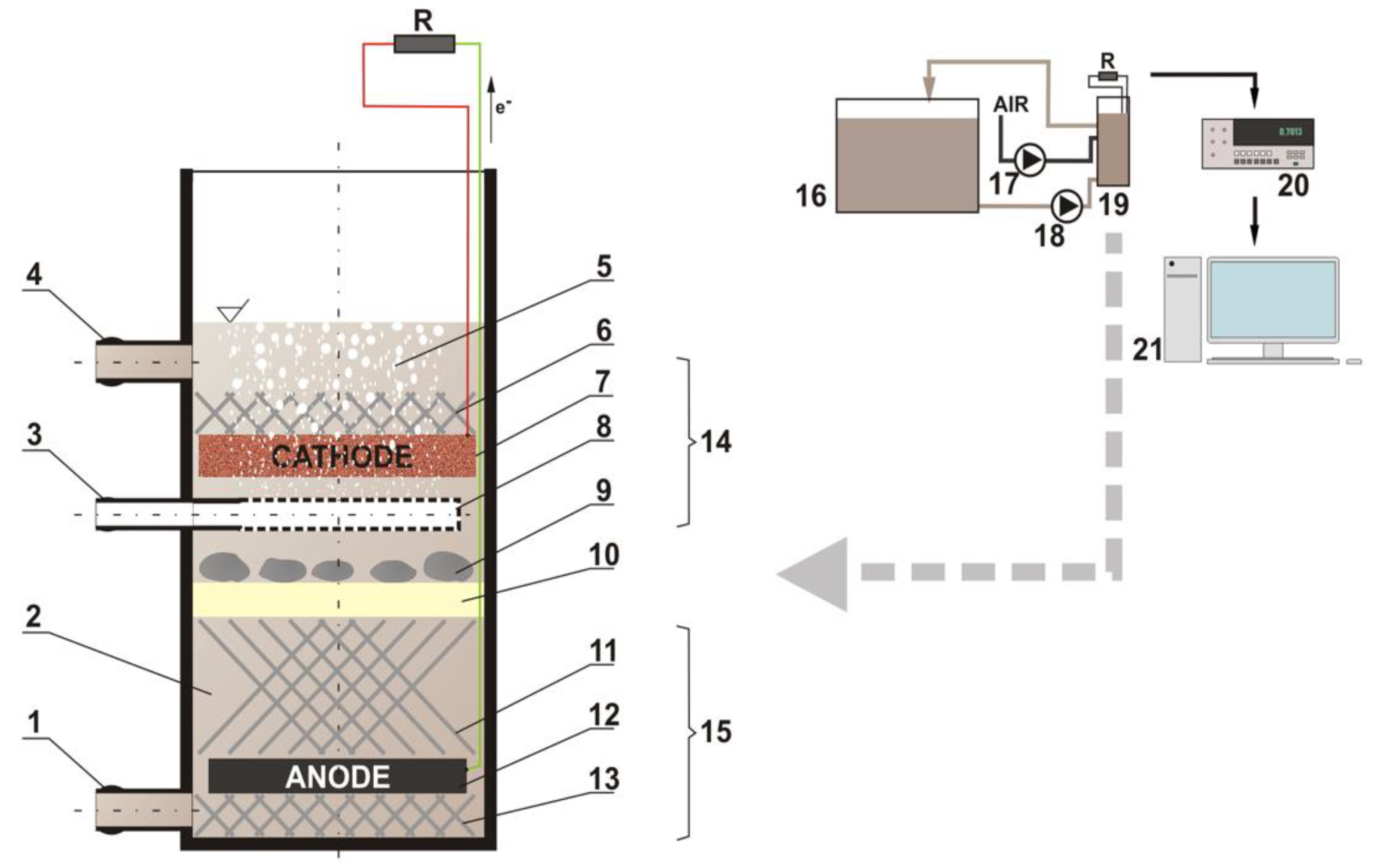
2.3. Measurements of Voltage and Power during the Operation of ML-MFC

In the measurements of the ML-MFC operation, the prepared alloys (copper-based) as cathodes were used. The research included electric energy production during the operation of the MFC.
In the measurements, the ML-MFC was used. Figure 1 shows the diagram (with components) of the ML-MFC applied in the measurements.
The used ML-MFC was the shape of a pipe with dimensions of 120 mm × 250 mm (diameter × height) with intake and outflow of the wastewater. The housing of the ML-MFC was printed with 3D printing technology. The elements for supporting electrodes and glass wool were also printed with 3D printing technology (6, 11, and 13 in Figure 1). The anode section was placed above the cathode section, and an air bubbler (8 in Figure 1) was placed in between. This arrangement ensures oxygenation of the cathode, and, at the same time, limits the oxygenation of wastewater in the anode section. Additionally, glass wool was used between the anode and the cathode (10 in Figure 1), which, in addition, separates the anode section from the cathode section. The stones (9 in Figure 1) hold the glass wool at a constant height.
Moreover, in ML-MFC, the slow circulation of wastewater in the direction from the anode to the cathode is ensured. This wastewater flow also prevents the oxygenation of the anode. ML-MFC was combined with the external wastewater tank (16 in Figure 1). Wastewater was circulated in a closed loop. The rate of circulating was low (0.05 L·h−1) to ensure stable conditions for the functioning of microorganisms in anaerobic conditions. The volume of wastewater in the entire system was 15 L (including an external tank).
The dimensions of the cathode (Cu-Ag) were 80 mm × 80 mm × 5 mm. The dimensions of the anode (carbon cloth) were similar to the dimensions of the cathode. The cathode was aerated (10 L·h−1) [63]. The ML-MFCs were constantly connected with a 10 Ω resistor [5,20,73,74].
For the present research process, yeast wastewater (PYWW) derived from yeast production was applied. For measurements, PYWW sourced from the averaging tank was used. In the averaging tank, the process effluents (from the first, second, and third centrifuges, vacuum filters, and molasses clarification) were mixed [75].
The microorganisms were obtained from activated sludge from a wastewater treatment plant. The time of microorganisms acclimatization was 5 days [4,18,63,76].
A Zortrax M200 3D printer was used to obtain the 3D printout and to prepare the 3D printouts for printing the Z-Suite software (Zortrax S.A, Olsztyn, Poland). For the experiments of the electroless potential and influence of anodic charge on the catalyst catalytic activity, an Amel System 500 potentiostat (Amel S.l.r., Milano, Italy) was used, and for the electrical measurements of ML-MFC, a Fluke 8840A multimeter (Fluke Corporation, Everett, WA, USA) was used. For the potentiostat controlling, a CorrWare software (Scribner Associates Inc., Southern Pines, NC, USA) was used. To deposit the catalyst onto the electrodes, PowerLab 305D-II was used. For the electrode preparation, an X-ray diffractometer (Xcalibur, Oxford Diffraction, Oxford, UK) and an LAC LH06/12 furnace (LAC s.r.o., Židlochovice, Czech Republic) were used (diffractometer: the electrodes selection; furnace: electrodes oxidation).

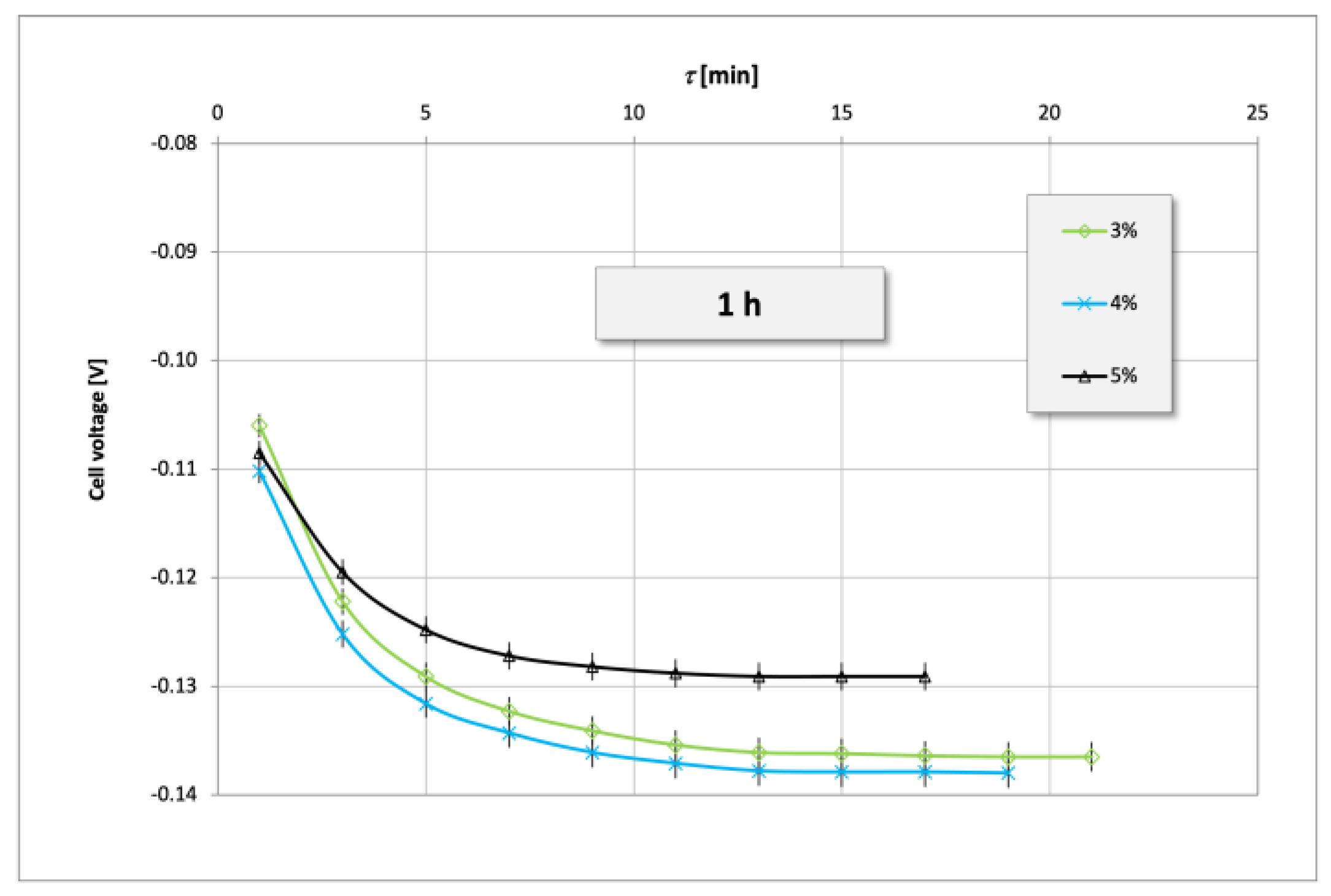
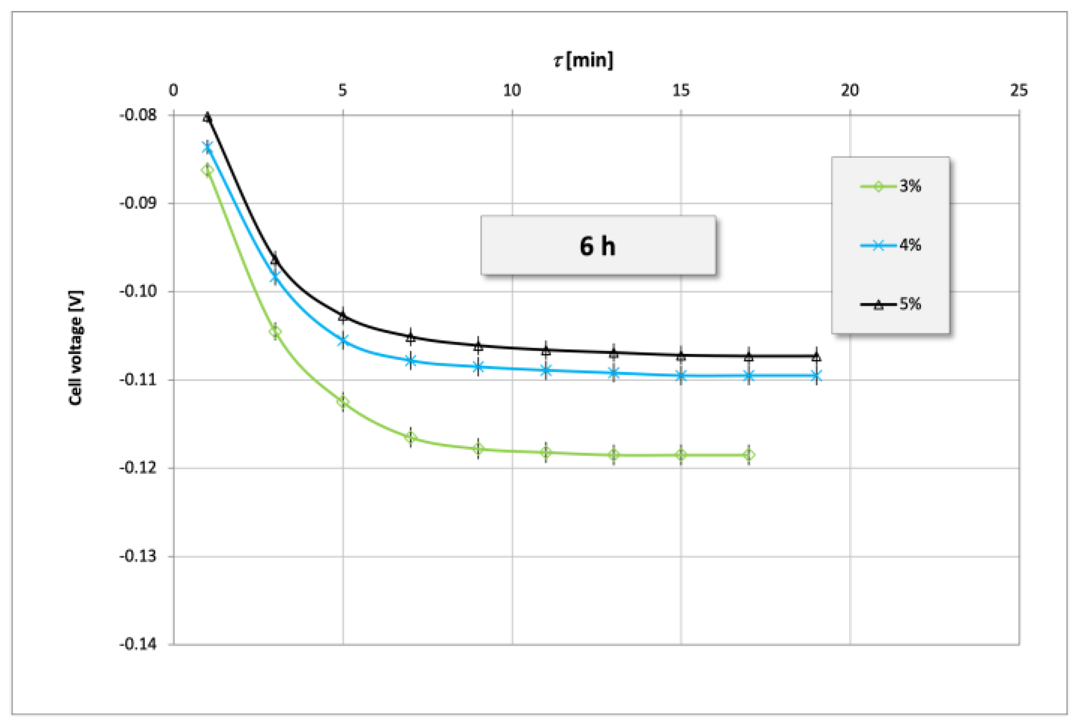
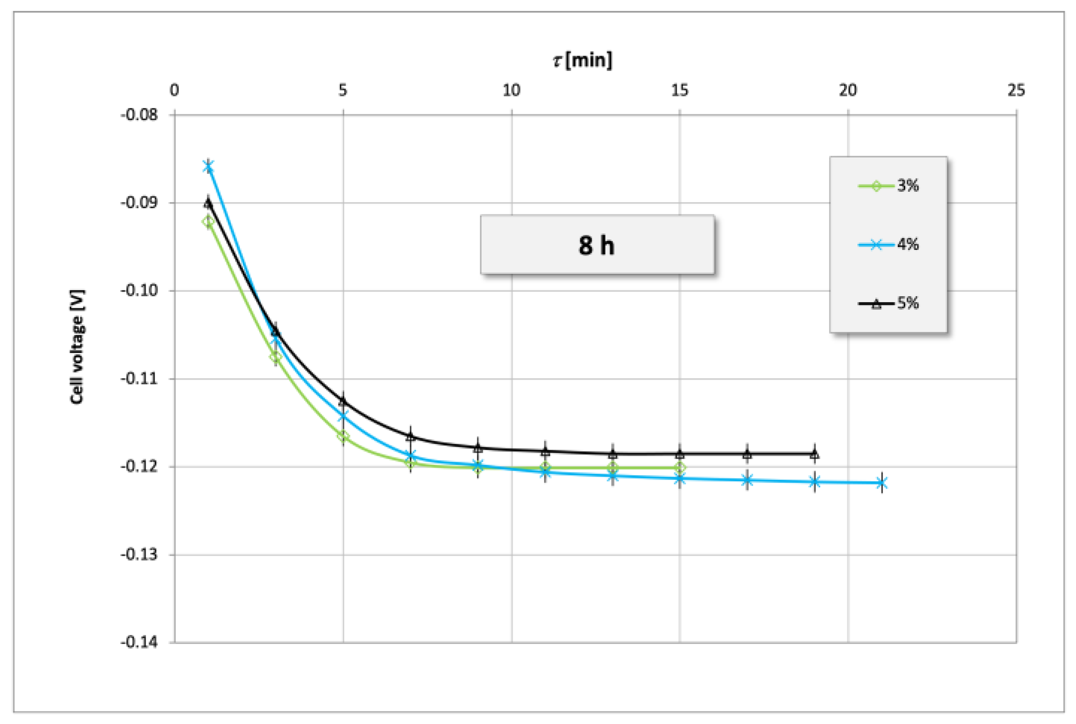
3. Results and Discussion

The first measurements were the measurements of the stationary potential of the oxidized cathodes. Figure 2, Figure 3, Figure 4 and Figure 5 show the electroless potential of Cu-Ag cathode oxidized for 1 (Figure 2), 3 (Figure 3), 6 (Figure 4), and 8 (Figure 5) h.
Next, the measurements of the influence of an anodic charge on the catalytic activity of the electrode (cathode) after 1st, 2nd, 3rd, and 4th anodic charging were taken.
Figure 6 shows the influence of an anodic charge on the voltage of a half-cell with Cu-Ag cathode with 3% of Ag. Figure 7 shows the influence of an anodic charge on the voltage of a half-cell with Cu-Ag cathode with 4% of Ag. Figure 8 shows the influence of an anodic charge on the voltage of a half-cell with Cu-Ag cathode with 5% of Ag.
The last step was to perform the measurements of the power and voltage obtained in ML-MFC (powered with PYWW) with copper-based cathodes (Table 2 and Table 3).
With the use of the Cu-Ag (with 3, 4, and 5% of Ag) cathode (oxidized for 1–8 h and without an anodic charge) used in the ML-MFC, the power and voltage were measured (Table 1). Table 2 shows the power and voltage obtained in ML-MFC with Cu cathode oxidized for 6 h and after an anodic charge (after 1, 2, 3, and 4 times of charging).
Table 3 shows the power and voltage obtained in ML-MFC with Cu-Ag cathode oxidized for 8 h, and after an anodic charge (after 1, 2, 3, 4 times of charging).
The curves of cell voltage in time and power of the ML-MFC for the highest values (data from Table 2 and Table 3) are presented in Figure 9 (cell voltage) and Figure 10 (power). Moreover, for comparison, Figure 9 and Figure 10 also cover the curves using the Cu-B catalysts. Results for the Cu-B alloys were obtained during previous research [26,58].
During the deposition, the Cu-Ag alloys with the share of 3, 4, and 5% of Ag were obtained. It was not possible to obtain alloys with a higher concentration of Ag. In the Cu-Ag alloy, the concentration of Ag was low because higher concentrations could not be obtained during deposition, probably mainly due to the depletion of Cu2+ and Ag+ ions in the bath, since these ions were not replenished as the samples were plated.
In the measurements of the electroless potential in all cases, the highest values were obtained for alloys with 5% content of Ag (Figure 2, Figure 3, Figure 4 and Figure 5). In the case of cathode oxidation in 1 and 3 hours, there is a large difference in the potential value for the 5% Ag electrode compared to the other 2 electrodes (3 and 4%) (Figure 2 and Figure 3). However, in the case of cathode oxidation in 6 hours, the potential of the electrode with 5% content of Ag was close to the potential of the electrode with 4% content of Ag (Figure 4). For the cathode oxidation in 8 hours, the electroless potential was similar for all electrodes (3, 4, and 5% of Ag) (Figure 5). However, the highest electroless potential of the Cu-Ag cathode without the anodic charge was obtained for the content of 5% of Ag and 6 h of oxidation time (Figure 4). After 8 hours of oxidation, all electrodes obtained similar electrode potential values (Figure 5) but much lower than in the case of 5% Ag content after 6 h of oxidation (Figure 4). This is due to the high oxidation of the electrode thus lowering the catalytic properties of the alloy. The oxidation of electrodes slightly decreases the electroless potential. However, due to the constant electrode (cathode) oxygenation, the catalyst is constantly, slowly oxidized. Without preliminary electrodes oxidation, the cell voltage drops over time. The pre-oxidized cathode retains its performance over time.
In the case of the influence of the anodic charge on cell potential, it was noted that the cell potential is changing with subsequent anodic charging (Figure 6, Figure 7 and Figure 8). In all cases, the best parameters were obtained after the third anodic charge (the darkest blue line in Figure 6, Figure 7 and Figure 8). For the Cu-Ag alloy with 3% content of Ag, the difference between the third and the other anodic charges is the largest (Figure 6). For the Cu-Ag alloy with 4% content of Ag, the subsequent anodic charge evenly improved the parameters of the cathode (Figure 7). However, the characteristic of the curve (for the Cu-Ag alloy with 4% content of Ag) after the first anodic charge is the least favorable (Figure 7). For the Cu-Ag alloy with 5% content of Ag, the difference between the third and fourth anodic charges is insignificant (Figure 8). However, the highest parameters were obtained for the content of 5% of Ag and after the third anodic charge (Figure 8). The charge causes those formations to result in worse catalytic properties; as result of increasing the anode charge, larger oxide layers are formed.
All the elements for the construction of the ML-MFC were printed with 3D printing technology. First, the various types of materials (in the form of a filament) were experimented. PLA (polylactic acid), ABS (acrylonitrile butadiene styrene), and HIPS (high impact polystyrene) were used for 3D printout tests. The 3D printouts quality varied. The PLA printout was characterized by very visible print layers (high surface roughness). The HIPS printout was peeling off the heated bed. This caused changes in the geometry in relation to the design. Finally, ABS was chosen as the material for printing the housing and support elements of the MFC. The thickness of the print layer was 90 μm. The ML-MFC (built for the purpose of this study) allowed to measure the power and voltage of this cell. In all cases, the analyzed ML-MFC generated the bio-electricity. The minimum cell power generated without an anodic charge was 3.98 mW (for 4% of Ag in alloy), while the lowest cell voltage was 0.72 V (for 5% of Ag in alloy) (Table 2). The minimum cell power generated after an anodic charge (for 5% of Ag in alloy) was 4.99 mW (for electrode after the first anodic charge), while the lowest cell voltage was 0.84 V (for electrode also after the first anodic charge) (Table 3). The average power obtained in the ML-MFC (for all contents of Ag in the catalyst and electrodes oxidized for 1–8 h) was 4.38 mW, while the average cell voltage was 0.83 mW (Table 2). In the case of the measurements after an anodic charge, the average power obtained in ML-MFC was 5.67 mW, whereas the average cell voltage was 0.93 mW (Table 3).
The highest power (5.11 mW) and cell voltage (0.89 V) for the Cu-Ag cathode with 5% of Ag and without an anodic charge were obtained for electrodes oxidized for 6 h (Table 2). In the case of the power and cell voltage obtained in the ML-MFC with electrodes after anodic charging, some changes were observed. The highest power (6.38 mW) and cell voltage (1.09 V) for the Cu-Ag cathode with 5% of Ag and without an anodic charge were obtained for electrodes oxidized for 6 h and after 4 times of anodic charging (Table 3).
It was noted that oxidation and anodic charge influence the catalytic activity of Cu-Ag electrodes. The results were compared with earlier studies of Cu-B electrodes (Figure 9) [26,63]. On this basis, it was observed that during the operation of the ML-MFC (fed with PYWW) for both electrodes (Cu-Ag and Cu-B), no significant voltage drops over time were observed. However, the obtained cell power is higher in the case of using the Cu-Ag cathode than in the case of the Cu-B cathode (Figure 10). However, it should be noted that the increase in power (compared to the Cu-B cathode) is not significant.

4. Conclusions

It should be noted that the development of any technologies which allow the recovery of energy from waste products is necessary as a part of the circular economy. The wider use of MFCs technology will make it possible to treat wastewater as a potential renewable energy source and not just a nuisance factor generating only the costs necessary for their disposal. In the era of the energy crisis, the depletion of fossil resources, and increasing public awareness regarding the interests of future generations, such an approach to use the potential of wastewater is rational and necessary.
This paper presents the results of a study regarding bio-electricity production in the ML-MFC (with Cu-Ag cathode) fed by PYWW. For all cases and for all alloys (all concentration of Ag), electricity was generated in the ML-MFC. The measurements showed that the Cu-Ag alloy containing 5% Ag (which was oxidized over 6 h and after 3 times of anodic charge) has the most favorable catalytic parameters. The ML-MFC powered by PYWW with such a catalyst obtained the power of 6.38 mW and the cell voltage of 1.09 V. The obtained parameters (e.g., cell voltage or power) were slightly higher than those obtained in the previous research of the bio-electricity production in the MFC with Cu-B cathode [26,58]. This research demonstrated that it is feasible to obtain the electricity in the ML-MFC with Cu-Ag cathode (fed by PYWW). This work showed that the right direction of research has been taken. However, further research of the deep analysis of the alloys, used as a catalyst of the cathode in MFC, is needed. Therefore, further work in wider scope is planned.

Author Contributions

Data curation, B.W.; investigation, P.P.W. and B.W.; methodology, P.P.W.; writing—original draft, B.W. and P.P.W.; writing—review and editing, B.W. and P.P.W.; supervision, B.W. and P.P.W. All authors have read and agreed to the published version of the manuscript.

Funding

This research received no external funding.

Conflicts of Interest

The authors declare no conflict of interest.

References

  1. Sadecka, Z. Podstawy Biologicznego Oczyszczania Ścieków; Wydawnictwo Seidel-Przywecki: Józefosław, Poland, 2010. [Google Scholar]
  2. Sikora, J.; Miksch, K. Biotechnologia Ścieków; Wydawnictwa Naukowe PWN: Warszawa, Poland, 2010. [Google Scholar]
  3. Bartkiewicz, B.; Umiejewska, K. Oczyszczanie Ścieków Przemysłowych; Wydawnictwa Naukowe PWN: Warszawa, Poland, 2020. [Google Scholar]
  4. Logan, B. Microbial Fuel Cells; Wiley: Hoboken, NJ, USA, 2008. [Google Scholar]
  5. Rabaey, K.; Verstraete, W. Microbial fuel cells: Novel biotechnology for energy generation. Trends Biotechnol. 2005, 23, 291–298. [Google Scholar] [CrossRef]
  6. Franks, A.E.; Nevin, K.P. Microbial fuel cells, a current review. Energies 2010, 3, 899–919. [Google Scholar] [CrossRef] [Green Version]
  7. Selihin, N.M.; Tay, M.G. A review on future wastewater treatment technologies: Micro-nanobubbles, hybrid electro-Fenton processes, photocatalytic fuel cells, and microbial fuel cells. Water Sci. Technol. 2022, 85, 319–341. [Google Scholar] [CrossRef] [PubMed]
  8. Min, B.; Logan, B.E. Continuous electricity generation from domestic wastewater and organic substrates in a flat plate microbial fuel cell. Environ. Sci. Technol. 2004, 38, 5809–5814. [Google Scholar] [CrossRef] [PubMed]
  9. Potter, M.C. Electrical effects accompanying the decomposition organic compounds. Proc. R. Soc. Lond. Ser. B 1911, 84, 260–276. [Google Scholar] [CrossRef]
  10. Bond, D.R.; Lovley, D.R. Electricity production by Geobacter sulfurreducens attached to electrodes. Appl. Environ. Microbiol. 2003, 69, 1548–1555. [Google Scholar] [CrossRef] [Green Version]
  11. Bond, D.R.; Lovley, D.R. Evidence for involvement of an electron shuttle in electricity generation by Geothrix fermentans. Appl. Environ. Microbiol. 2005, 71, 2186–2189. [Google Scholar] [CrossRef] [Green Version]
  12. Park, H.S.; Kim, B.H.; Kim, H.S.; Kim, H.J.; Kim, G.T.; Kim, M.; Chang, I.S.; Park, Y.K.; Chang, H.I. A novel electrochemically active and Fe(III)-reducing bacterium phylogenetically related to Clostridium butyricum isolated from a microbial fuel cell. Anaerobe 2001, 7, 297–306. [Google Scholar] [CrossRef]
  13. Kim, H.J.; Park, H.S.; Hyun, M.S.; Chang, I.S.; Kim, M.; Kim, B.H. A Mediator-Less Microbial Fuel Cell Using a Metal Reducing Bacterium, Shewanella putrefaciens. Enzym. Microb. Technol. 2002, 30, 145–152. [Google Scholar] [CrossRef]
  14. Reguera, G.; Nevin, K.P.; Nicoll, J.S.; Covalla, S.F.; Woodard, T.L.; Lovley, D.R. Biofilm and nanowire production leads to incre- ased current in Geobacter sulfurreducens fuel cells. Appl. Environ. Microbiol. 2006, 72, 7345–7348. [Google Scholar] [CrossRef] [Green Version]
  15. Chaudhuri, S.K.; Lovley, D.R. Electricity generation by direct oxidation of glucose in mediatorless microbial fuel cells. Nat. Biotechnol. 2003, 21, 1229–1232. [Google Scholar] [CrossRef]
  16. Reguera, G.; McCarthy, K.D.; Mehta, T.; Nicoll, J.S.; Tuominen, M.T.; Lovley, D.R. Extracellular electron transfer via microbial nanowires. Nature 2005, 435, 1098–1101. [Google Scholar] [CrossRef]
  17. Pham, C.A.; Jung, S.J.; Phung, N.T.; Lee, J.; Chang, I.S.; Kim, B.H.; Yi, H.; Chun, J. A novel electrochemically active and Fe(III)-reducing bacterium phylogenetically related to Aeromonas hydrophila, isolated from a microbial fuel cell. FEMS Microbiol. Lett. 2003, 223, 129–134. [Google Scholar] [CrossRef] [PubMed] [Green Version]
  18. Logan, B.E.; Hamelers, B.; Rozendal, R.; Schroder, U.; Keller, J.; Verstraete, W.; Rabaey, K. Microbial fuel cells:  Methodology and technology. Environ. Sci. Technol. 2006, 40, 5181–5192. [Google Scholar] [CrossRef]
  19. Saha, T.C.; Protity, A.T.; Zohora, F.T.; Shaha, M.; Ahmed, I.; Barua, E.; Sarker, P.K.; Mukherjee, S.K.; Barua, A.; Salimullah, M.; et al. Microbial Fuel Cell (MFC) Application for Generation of Electricity from Dumping Rubbish and Identification of Potential Electrogenic Bacteria. Adv. Ind. Biotechnol. 2019, 2, 1–8. [Google Scholar] [CrossRef]
  20. Halim, M.A.; Rahman, M.O.; Eti, I.A.; Shefa, N.R.; Ibrahim, M.; Alam, M.J. Electricity generation in different cell connections with optimized anodic materials in microbial fuel cells. Energy Sources Part A Recovery Util. Environ. Eff. 2020. [Google Scholar] [CrossRef]
  21. Sharan, S.; Khare, P.; Shankar, R.; Patel Ratnesh, K.; Mondal, P. Simultaneous removal of organics and bioenergy production by microbial fuel cell: Modeling approach. Int. J. Chem. React. Eng. 2021, 19, 1351–1362. [Google Scholar] [CrossRef]
  22. Włodarczyk, P.P.; Włodarczyk, B. Preparation and Analysis of Ni–Co Catalyst Use for Electricity Production and COD Reduction in Microbial Fuel Cells. Catalysts 2019, 9, 1042. [Google Scholar] [CrossRef] [Green Version]
  23. Chang, C.; Gupta, P. Economical and sustainable microbial peroxide-producing cell utilizing domestic sewage water and its contemporaneous treatment. Fuel Cells 2022, 22, 186–196. [Google Scholar] [CrossRef]
  24. Rojas-Flores, S.; De La Cruz-Noriega, M.; Benites, S.M.; Delfín-Narciso, D.; Luis, A.-S.; Díaz, F.; Luis, C.-C.; Moises, G.C. Electric Current Generation by Increasing Sucrose in Papaya Waste in Microbial Fuel Cells. Molecules 2022, 27, 5198. [Google Scholar] [CrossRef]
  25. Włodarczyk, P.P.; Włodarczyk, B. Microbial Fuel Cell with Ni–Co Cathode Powered with Yeast Wastewater. Energies 2018, 11, 3194. [Google Scholar] [CrossRef] [Green Version]
  26. Włodarczyk, B.; Włodarczyk, P.P. The Membrane-Less Microbial Fuel Cell (ML-MFC) with Ni-Co and Cu-B Cathode Powered by the Process Wastewater from Yeast Production. Energies 2020, 13, 3976. [Google Scholar] [CrossRef]
  27. Abubackar, H.N.; Biryol, I.; Ayol, A. Yeast industry wastewater treatment with microbial fuel cells: Effect of electrode materials and reactor configurations. Int. J. Hydrog. Energy 2022, in press. [CrossRef]
  28. Wilberforce, T.; Sayed, E.T.; Abdelkareem, M.A.; Elsaid, K.; Olabi, A.G. Value added products from wastewater using bioelectrochemical systems: Current trends and perspectives. J. Water Process Eng. 2021, 39, 101737. [Google Scholar] [CrossRef]
  29. Urbina-Suarez, N.A.; Machuca-Martínez, F.; Barajas-Solano, A.F. Advanced Oxidation Processes and Biotechnological Alternatives for the Treatment of Tannery Wastewater. Molecules 2021, 26, 3222. [Google Scholar] [CrossRef] [PubMed]
  30. Karuppiah, T.; Uthirakrishnan, U.; Sivakumar, S.V.; Authilingam, S.; Arun, J.; Sivaramakrishnan, R.; Pugazhendhi, A. Processing of electroplating industry wastewater through dual chambered microbial fuel cells (MFC) for simultaneous treatment of wastewater and green fuel production. Int. J. Hydrog. Energy 2022, 47, 37569–37576. [Google Scholar] [CrossRef]
  31. Rojas-Flores, S.; De La Cruz Noriega, M.; Benites, S.M.; Gonzales, G.A.; Salinas, A.S.; Palacios, F.S. Generation of bioelectricity from fruit waste. Energy Rep. 2020, 6, 37–42. [Google Scholar] [CrossRef]
  32. Segundo, R.-F.; De La Cruz-Noriega, M.; Nazario-Naveda, R.; Benites, S.M.; Delfín-Narciso, D.; Angelats-Silva, L.; Díaz, F. Golden Berry Waste for Electricity Generation. Fermentation 2022, 8, 256. [Google Scholar] [CrossRef]
  33. Rojas-Flores, S.; Benites, S.M.; De La Cruz-Noriega, M.; Cabanillas-Chirinos, L.; Valdiviezo-Dominguez, F.; Quezada Álvarez, M.A.; Vega-Ybañez, V.; Angelats-Silva, L. Bioelectricity Production from Blueberry Waste. Processes 2021, 9, 1301. [Google Scholar] [CrossRef]
  34. Rojas-Flores, S.; De La Cruz-Noriega, M.; Nazario-Naveda, R.; Benites, S.M.; Delfín-Narciso, D.; Angelats-Silva, L.; Murga-Torres, E. Use of Banana Waste as a Source for Bioelectricity Generation. Processes 2022, 10, 942. [Google Scholar] [CrossRef]
  35. Segundo, R.-F.; De La Cruz-Noriega, M.; Milly Otiniano, N.; Benites, S.M.; Esparza, M.; Nazario-Naveda, R. Use of Onion Waste as Fuel for the Generation of Bioelectricity. Molecules 2022, 27, 625. [Google Scholar] [CrossRef]
  36. Feng, Y.; Wang, X.; Logan, B.E.; Lee, H. Brewery wastewater treatment using air-cathode microbial fuel cells. Appl. Microbiol. Biotechnol. 2008, 78, 873–880. [Google Scholar] [CrossRef] [PubMed]
  37. Wen, Q.; Wu, Y.; Cao, D.; Zhao, L.; Sun, Q. Electricity generation and modeling of microbial fuel cell from continuous beer brewery wastewater. Bioresour. Technol. 2009, 100, 4171–4175. [Google Scholar] [CrossRef] [PubMed]
  38. Munoz-Cupa, C.; Hu, Y.; Xu, C.; Bassi, A. An overview of microbial fuel cell usage in wastewater treatment, resource recovery and energy production. Sci. Total Environ. 2021, 754, 142429. [Google Scholar] [CrossRef] [PubMed]
  39. Yuan, Y.; Zhou, S.; Zhuang, L. Polypyrrole/carbon black composite as a novel oxygen reduction catalyst for microbial fuel cells. J. Power Sources 2010, 195, 3490–3493. [Google Scholar] [CrossRef]
  40. Zuo, K.; Liang, S.; Liang, P.; Zhou, X.; Sun, D.; Zhang, X.; Huang, X. Carbon filtration cathode in microbial fuel cell to enhance wastewater treatment. Bioresour. Technol. 2015, 185, 426–430. [Google Scholar] [CrossRef]
  41. Liu, Y.; Harnisch, F.; Fricke, K.; Schroeder, U.; Climent, V.; Feliu, J.M. The study of electrochemically active microbial biofilms on different carbon-based anode materials in microbial fuel cells. Biosens. Bioelectron. 2010, 25, 2167–2171. [Google Scholar] [CrossRef]
  42. Sanchez, D.V.P.; Huynh, P.; Kozlov, M.E.; Baughman, R.H.; Vidic, R.D.; Yun, M. Carbon Nanotube/Platinum (Pt) Sheet as an Improved Cathode for Microbial Fuel Cells. Energy Fuels 2010, 24, 5897–5902. [Google Scholar] [CrossRef]
  43. Kosimaningrum, W.E.; Ouis, M.; Holade, Y.; Buchari, B.; Noviandri, I.; Kameche, M.; Cretin, M.; Innocent, C. Platinum Nanoarrays Directly Grown onto a 3D-Carbon Felt Electrode as a Bifunctional Material for Garden Compost Microbial Fuel Cell. J. Electrochem. Soc. 2021, 168, 025501. [Google Scholar] [CrossRef]
  44. Santoro, C.; Kodali, M.; Herrera, S.; Serov, A.; Ieropoulos, I.; Atanassov, P. Power generation in microbial fuel cells using platinum group metal-free cathode catalyst: Effect of the catalyst loading on performance and costs. J. Power Sources 2018, 378, 169–175. [Google Scholar] [CrossRef]
  45. Park, H.I.; Mushtaq, U.; Perello, D.; Lee, I.; Cho, S.K.; Star, A.; Yun, M. Effective and Low-Cost Platinum Electrodes for Microbial Fuel Cells Deposited by Electron Beam Evaporation. Energy Fuels 2007, 21, 2984–2990. [Google Scholar] [CrossRef]
  46. Liew, K.B.; Daud, W.R.W.; Ghasemia, M.; Leong, J.X.; Lim, S.S.; Ismail, M. Non-Pt catalyst as oxygen reduction reaction in microbial fuel cells: A review. Int. J. Hydrogen Energy 2014, 39, 4870–4883. [Google Scholar] [CrossRef]
  47. Morris, J.M.; Jin, S.; Wang, J.; Zhu, C.; Urynowiczcz, M.A. Lead dioxide as an alternative catalyst to platinum in microbial fuel cells. Electrochem. Commun. 2007, 9, 1730–1734. [Google Scholar] [CrossRef]
  48. Zhang, L.; Liu, C.; Zhuang, L.; Li, W.; Zhou, S.; Zhang, J. Manganese dioxide as an alternative cathodic catalyst to platinum in microbial fuel cells. Biosens. Bioelectron. 2009, 24, 2825–2829. [Google Scholar] [CrossRef]
  49. Santoro, C.; Lei, Y.; Li, B.; Cristianid, P. Power generation from wastewater using single chamber microbial fuel cells (MFCs) with platinum-free cathodes and pre-colonized anodes. Biochem. Eng. J. 2012, 62, 8–16. [Google Scholar] [CrossRef]
  50. Arkatkar, A.; Mungray, A.M.; Sharma, P. Biological modification in air-cathode microbial fuel cell: Effect on oxygen diffusion, current generation and wastewater degradation. Chemosphere 2021, 284, 131243. [Google Scholar] [CrossRef] [PubMed]
  51. Zhang, F.; Cheng, S.; Pant, D.; Van Bogaert, G.; Logan, B.E. Power generation using an activated carbon and metal mesh cathode in a microbial fuel cell. Electrochem. Commun. 2009, 11, 2177–2179. [Google Scholar] [CrossRef]
  52. Taşkan, B. Increased power generation from a new sandwich-type microbial fuel cell (ST-MFC) with a membrane-aerated cathode. Biomass Bioenergy 2020, 142, 105781. [Google Scholar] [CrossRef]
  53. Cheng, S.; Liu, H.; Logan, B.E. Power Densities Using Different Cathode Catalysts (Pt and CoTMPP) and Polymer Binders (Nafion and PTFE) in Single Chamber Microbial Fuel Cells. Environ. Sci. Technol. 2006, 40, 364–369. [Google Scholar] [CrossRef]
  54. Lilloja, J.; Mooste, M.; Kibena-Põldsepp, E.; Sarapuu, A.; Kikas, A.; Kisand, V.; Käärik, M.; Kozlova, J.; Treshchalov, A.; Paiste, P.; et al. Cobalt-, iron- and nitrogen-containing ordered mesoporous carbon-based catalysts for anion-exchange membrane fuel cell cathode. Electrochim. Acta 2023, 439, 141676. [Google Scholar] [CrossRef]
  55. Li, M.; Zhou, S.; Xu, M. Graphene oxide supported magnesium oxide as an efficient cathode catalyst for power generation and wastewater treatment in single chamber microbial fuel cells. Chem. Eng. J. 2017, 328, 106–116. [Google Scholar] [CrossRef]
  56. Kodali, M.; Gokhale, R.; Santoro, C.; Serov, A.; Artyushkova, K.; Atanassov, P. High Performance Platinum Group Metal-Free Cathode Catalysts for Microbial Fuel Cell (MFC). J. Electrochem. Soc. 2017, 164, H3041–H3046. [Google Scholar] [CrossRef]
  57. Li, S.; Hu, Y.; Xu, Q.; Sun, J.; Hou, B.; Zhang, Y. Iron- and nitrogen-functionalized graphene as a non-precious metal catalyst for enhanced oxygen reduction in an air-cathode microbial fuel cell. J. Power Sources 2012, 213, 265–269. [Google Scholar] [CrossRef]
  58. Wang, W.; Zhao, Q.; Ding, J.; Wang, K.; Jiang, J. Development of an MFC-powered BEF system with novel Fe-Mn-Mg/CF composite cathode to degrade refractory pollutants. J. Clean. Prod. 2021, 326, 129348. [Google Scholar] [CrossRef]
  59. Martin, E.; Tartakovsky, B.; Savadogo, O. Cathode materials evaluation in microbial fuel cells: A comparison of carbon, Mn2O3, Fe2O3 and platinum materials. Electrochim. Acta 2011, 58, 58–66. [Google Scholar] [CrossRef] [Green Version]
  60. Parveen, N.; Hiep Han, T.; Ali Ansari, S.; Lee, M. Sustainable Bio-Energy Production in Microbial Fuel Cell Using MnO2 Nanoparticle-Decorated Hollow Carbon Nanofibers as Active Cathode Materials. J. Nanoelectron. Optoelectron. 2021, 16, 127–135. [Google Scholar] [CrossRef]
  61. Włodarczyk, B.; Włodarczyk, P.P. Comparsion of Cu-B alloy and stainless steel as electrode material for microbial fuel cell. In Renewable Energy Sources: Engineering, Technology, Innovation ICORES 2018; Wróbel, M., Jewiarz, M., Szlęk, A., Eds.; Springer Nature Switzerland AG: Basel, Switzerland, 2020; pp. 1057–1063. [Google Scholar] [CrossRef]
  62. Włodarczyk, B.; Włodarczyk, P.P. Methanol electrooxidation with Cu-B catalyst. Infrastruct. Ecol. Rural Areas (Polish Acad. Sci. Crac.) 2016, 4, 1483–1492. [Google Scholar] [CrossRef]
  63. Włodarczyk, P.P.; Włodarczyk, B. Wastewater Treatment and Electricity Production in a Microbial Fuel Cell with Cu-B Alloy as the Cathode Catalyst. Catalysts 2019, 9, 572. [Google Scholar] [CrossRef] [Green Version]
  64. Włodarczyk, P.P.; Włodarczyk, B. Feasibility of Waste Engine Oil Electrooxidation with Ni-Co and Cu-B Catalysts. Energies 2022, 15, 7686. [Google Scholar] [CrossRef]
  65. Antolini, E.; Cardellini, F. Formation of carbon supported Pt-Ru alloys: An XRD analysis. J. Alloys Compd. 2001, 315, 118–122. [Google Scholar] [CrossRef]
  66. Motl, N.E.; Ewusi-Annan, E.; Sines, I.T.; Jensen, L.; Schaak, R.E. Au-Cu Alloy Nanoparticles with Tunable Compositions and Plasmonic Properties: Experimental Determination of Composition and Correlation with Theory. J. Phys. Chem. C 2010, 114, 19263–19269. [Google Scholar] [CrossRef]
  67. Antolini, E.; Giorgi, L.; Cardellini, F.; Passalacqua, E. Physical and morphological characteristics and electrochemical behaviour in PEM fuel cells of PtRu/C catalysts. J. Solid State Electrochem. 2001, 5, 131–140. [Google Scholar] [CrossRef] [Green Version]
  68. Antolini, E.; Cardellini, F.; Giorgi, L. Effect of Me (Pt + Ru) content in Me/C catalysts on PtRu alloy formation: An XRD analysis. J. Mater. Sci. Lett. 2000, 19, 2099–2103. [Google Scholar] [CrossRef]
  69. Tench, D.M.; White, J.T. A New Periodic Displacement Method Applied to Electrodeposition of Cu-Ag Alloys. J. Electrochem. Soc. 1992, 139, 443. [Google Scholar] [CrossRef]
  70. Bernasconi, R.; Hart, J.L.; Lang, A.C.; Magagnin, L.; Nobili, L.; Taheri, M.L. Structural properties of electrodeposited Cu-Ag alloys. Electrochim. Acta 2017, 251, 475–481. [Google Scholar] [CrossRef]
  71. Shao, W.; Sun, Y.; Zangari, G. Electrodeposition of Cu-Ag Alloy Films at n-Si(001) and Polycrystalline Ru Substrates. Coatings 2021, 11, 1563. [Google Scholar] [CrossRef]
  72. Holtzer, M.; Staronka, A. Chemia fizyczna: Wprowadzenie; Wydawnictwa AGH: Cracow, Poland, 2000. [Google Scholar]
  73. Permana, D. Performance of Single Chamber Microbial Fuel Cell (SCMFC) for biological treatment of tofu wastewater. Proc. IOP Conf. Ser. Earth Environ. Sci. 2019, 277, 012008. [Google Scholar] [CrossRef]
  74. Pham, T.H.; Rabaey, K.; Aelterman, P.; Clauwaert, P.; De Schamphelaire, L.; Boon, N.; Verstraete, W. Microbial Fuel Cells in Relation to Conventional Anaerobic Digestion Technology. Eng. Life Sci. 2006, 6, 285–292. [Google Scholar] [CrossRef]
  75. Włodarczyk, B.; Włodarczyk, P.P. Analysis of the Potential of an Increase in Yeast Output Resulting from the Application of Additional Process Wastewater in the Evaporator Station. Appl. Sci. 2019, 9, 2282. [Google Scholar] [CrossRef] [Green Version]
  76. Huggins, T.; Fallgren, P.H.; Jin, S.; Ren, Z.J. Energy and performance comparison of microbial fuel cell and conventional aeration treating of wastewater. J. Microb. Biochem. Technol. 2013, S6, 1–5. [Google Scholar] [CrossRef] [Green Version]
Figure 1. Scheme of the membrane-less microbial fuel cell (ML-MFC) and measuring setup for measuring electrical parameters during operation of ML-MFC: 1—wastewater intake (from wastewater tank); 2—process yeast wastewater; 3—air intake for the cathode aeration; 4—wastewater outflow (to external wastewater tank); 5—air bubbles; 6—cathode support element; 7—cathode; 8—pipe with holes (bubbler); 9—stones; 10—glass wool; 11—anode and glass wool support element; 12—anode; 13—anode support element; 14—cathode section; 15—anode section; 16—wastewater tank; 17—air pump; 18—wastewater pump; 19—membrane-less microbial fuel cell (ML-MFC); 20—multimeter; 21—computer; and R—load.
Energies 16 02734 g001
Figure 2. Cu-Ag cathode oxidized for 1 h—the electroless potential of cathode.
Energies 16 02734 g002
Figure 3. Cu-Ag cathode oxidized for 3 h—the electroless potential of cathode.
Energies 16 02734 g003
Figure 4. Cu-Ag cathode oxidized for 6 h—the electroless potential of cathode.
Energies 16 02734 g004
Figure 5. Cu-Ag cathode oxidized for 8 h—the electroless potential of cathode.
Energies 16 02734 g005
Figure 6. Influence of an anodic charge on the voltage of a half-cell with Cu-Ag (3% of Ag) electrode—influence on the catalytic activity of electrode (lines 1–4 corresponding with 1st, 2nd, 3rd, and 4th anodic charge).
Energies 16 02734 g006
Figure 7. Influence of an anodic charge on the voltage of a half-cell with Cu-Ag (4% of Ag) electrode—influence on the catalytic activity of electrode (lines 1–4 corresponding with 1st, 2nd, 3rd, and 4th anodic charge).
Energies 16 02734 g007
Figure 8. Influence of an anodic charge on the voltage of a half-cell with Cu-Ag (5% of Ag) electrode—influence on the catalytic activity of electrode (lines 1–4 corresponding with 1st, 2nd, 3rd, and 4th anodic charge).
Energies 16 02734 g008
Figure 9. Curves of cell voltage in time (obtained during the ML-MFC operation). Cathode: Cu-Ag (5% of Ag, after 6 h of oxidizing and after 3 times of anodic charge); and Cu-B (9% of B, after 8 h of oxidizing and after 3 times of anodic charge) for comparison [26,63].
Energies 16 02734 g009
Figure 10. Power curves obtained during the ML-MFC operation. Cathode: Cu-Ag (5% of AG, after 6 h of oxidizing and after 3 times of anodic charge); and Cu-B (9% of B, after 8 h of oxidizing and after 3 times of anodic charge) for comparison [26,63].
Energies 16 02734 g010
Table 1. Composition of the mixture applied for catalyst deposition (Cu-Ag alloy).
ComponentVolume
AgNO30.02 mol·L−1
CuSO4·7H2O0.05 mol·L−1
Trilon B0.12 mol·L−1
NaOH1.00 mol·L−1
Table 2. Power and voltage (maximum value) obtained in ML-MFC (powered with PYWW). Cathode: Cu-Ag (foam form) oxidized for 1–8 h.
Oxidizing Time of the Cu-Ag
[h]
Max Power Obtained in ML-MFC
[mW]
Average Voltage of the ML-MFC
[V]
Content of Ag in the Alloy (%)Content of Ag in the Alloy (%)
345345
14.013.984.030.820.810.72
34.054.164.310.840.830.78
64.114.465.110.860.850.89
84.265.035.010.870.880.81
Table 3. Power and voltage (maximum value) obtained in ML-MFC (powered with PYWW). Cathode: Cu-Ag (foam form) oxidized for 6 h, and after an anodic charge (after 1, 2, 3, 4 times of charging).
Content of Ag
[%]
Max Power Obtained in ML-MFC
[mW]
Average Voltage of the ML-MFC
[V]
Number of Anodic ChargeNumber of Anodic Charge
12341234
34.995.155.495.120.840.850.870.91
45.655.815.995.460.910.920.990.94
55.795.956.385.920.910.911.090.98
Disclaimer/Publisher’s Note: The statements, opinions and data contained in all publications are solely those of the individual author(s) and contributor(s) and not of MDPI and/or the editor(s). MDPI and/or the editor(s) disclaim responsibility for any injury to people or property resulting from any ideas, methods, instructions or products referred to in the content.

