Review

Latent Heat Storage Systems for Thermal Management of Electric Vehicle Batteries: Thermal Performance Enhancement and Modulation of the Phase Transition Process Dynamics: A Literature Review

Faculty of Engineering, Constantin Brâncuși University of Târgu-Jiu, 210185 Târgu Jiu, Romania
*
Author to whom correspondence should be addressed.
Energies 2023, 16(6), 2745; https://doi.org/10.3390/en16062745
Submission received: 7 February 2023 / Revised: 27 February 2023 / Accepted: 13 March 2023 / Published: 15 March 2023
(This article belongs to the Special Issue A Themed Issue Dedicated to Professor Luisa F. Cabeza)

Abstract

:
Electric vehicles battery systems (EVBS) are subject to complex charging/discharging processes that produce various amount of stress and cause significant temperature fluctuations. Due to the variable heat generation regimes, latent heat storage systems that can absorb significant amounts of thermal energy with little temperature variation are an interesting thermal management solution. A major drawback of organic phase change materials is their low thermal conductivity, which limits the material charging/discharging capacity. This review paper covers recent studies on thermal performance enhancement of PCM thermal management for electric vehicles batteries. A special focus is placed on the constraints related to electric vehicles battery systems, such as mass/volume minimization, integration with other battery thermal management systems, operational temperature range, adaptability to extreme regimes and modulation of the melting/solidification behavior. The main research outcomes are as follows: quantitative/comparative assessment of common enhancement technique in terms of performance; approaches to deal with special constraints related to EVBS from the thermal control point of view.

1. Introduction

Thermal management for EV battery systems.
The transportation sector contributes a considerable share of total carbon emissions. Approximately 49% of the world oil resources are directed to the transportation sector, Amjad et al. [1]. Efforts to reduce the impact of transportation on climate change has resulted in the rapid development of electric mobility technologies. Electric vehicle requirements in terms of power supply include high voltage, high specific energy, portability, low rate of self-discharge, tolerance to temperature fluctuations, and long operational life, Aneke and Wang [2]. Lithium-ion battery systems satisfy these requirements to the highest degree for plug-in hybrid and pure electric vehicles. However, they have other issues such as sensitivity to temperature, Goutam et al. [3] and vibration, Andwari et al. [4]. The battery thermal management system (BTMS) is a key component of the overall battery system, which must ensure the optimum operating conditions for the battery system. It is also a critical EV system, since its failure can result in irreversible damage of the battery system or even fire. Several review papers report the main technology challenges that need to be resolved. Wang et al. [5] conducted a literature review addressing various battery system models and existing thermal management strategies. Jaguemont and Van Mierlo [6] reviewed traditional BTMS as well as novel hybrid systems, focusing on identifying advantages/disadvantages of each type. Thakur et al. [7] reviewed the current and experimental methods for cooling the EV battery systems. The cooling techniques were analyzed in the context of (1) heat generation governing models and (2) thermal issues emerging from improper thermal management.
Increasing the thermal performance of BTMSs is a matter of utmost concern. Since the EV battery system is a key component and a Single Point of Failure with considerable weight in the vehicle mass, it is critical to ensure the operational conditions specified by the manufacturer in order to obtain the overall performance of the vehicle. Various BTMS thermal performance enhancement techniques exist:
Shukla et al. [8] investigated experimentally the effect of vibrations on EV battery systems temperature. It was reported that the heat transfer was intensified at vibration frequencies of 20 and 30 Hz, and no noticeable influence was observed at 10 Hz. For a fixed frequency, a more intense heat exchange was observed at the increase of the vibration amplitude.
Lai et al. [9] proposed a novel interlayer BTMS employing Tesla-valve mini-channels to remove the heat dissipated in high-power density cell-pack bodies. The effect of the cold plate position and the Tesla-valve geometric parameters were investigated in order to optimize the battery performance by means of numerical simulation.
Shen et al. [10] presented a modified Z-shaped air-cooling system with an oblique structure and investigated numerically the thermal behavior of a lithium iron phosphate power battery. A tilted arrangement of the battery pack with various angles was used, forming a non-vertical flow channel. It was reported that in comparison with the conventional Z-shaped air-cooling system, the maximum temperature of the battery pack decreased from 38.15 °C to 34.14 °C (10.5%). The temperature difference (the maximum difference between various cells) decreased from 2.59 °C to 1.97 °C (23.9%).
From a thermal point of view, EV batteries are multiple-constraint systems. In addition to the optimum temperature range for Li-ion batteries, which is between 20 and 50 °C (Jilte et al. [11] Jilte et al. [12]), constraints related to mass/volume, heat storage capacity, and dynamic heat storage/release regimes must be considered in the proper thermal design of such systems. Two more factors add further complications to the EV BTMS: the highly variable and unpredictable operation regime and exposure to large environmental temperature excursions. BTMSs based on PCMs take advantage of the heat storage/release during the phase transition process, which occurs at a nearly constant temperature. Thus, a significant amount of thermal energy can be stored/released with a temperature variation as low as a few degrees.
Verma et al. [13] presented a numerical study in which a PCM-based thermal regulation system was employed to control an EV battery temperature under two ambient temperature conditions, 294 K and 323 K. Capric Acid (CA) was used as PCM with the melting temperature range 302–305 K and latent heat 152.7 kJ/kg. It was reported that a 3 mm PCM layer applied on the battery surface was able to reduce the battery temperature within 7 deg. of the ambient temperature 294 K. At the ambient temperature 323 K, the PCM alone did not manage to maintain the battery temperature within operational limits. It was concluded that a liquid-based active cooling system was required.
Several recent review studies on the topic of BTMS performance improvement are: Zhao et al. [14] conducted a review on optimization of BTMSs based on active liquid cooling; Weragoda et al. [15] carried out a review on BTMS performance enhancement techniques employing heat pipes; Ghaeminezhad et al. [16] presented from a control-oriented perspective a review paper classifying the recent BTMS methods for the Li-ion battery packs, introducing the concepts of feedback-based and non-feedback-based approaches; Li et al. [17] reviewed machine learning techniques employed in the study and optimization of BTMSs.
This review paper discusses the techniques used to enhance the thermal conductivity of PCMs used in BTMSs in the context of the unique requirements and constraints for such applications: low mass and occupied space, stability, reliability, containment, low energy requirements, and circular economy. A considerable number of techniques and studies exist on the enhancement of the PCM-based latent heat storage systems. However, not all techniques are applicable to the BTMSs given the special constraints of such thermal systems. Therefore, enhancement techniques must be properly adapted considering the specific issues of the BTMSs.
To our knowledge, this is the first review study discussing the modulation of PCMs thermal behavior to increase the flexibility of the BTMS to a wide range of operation regimes. Tuning the thermo-physical properties of PCMs (mainly the melting point and the latent heat) is a new concept and research direction; a literature survey on this particular topic was carried out in this review paper.
This review paper first presents general battery systems issues. This introductory discussion is necessary to set the context for the actual topic, which is the thermal performance enhancement of the BTMSs based on latent heat storage. In the second part of the paper, passive and then active enhancement techniques for PCM-based BTMSs are reviewed. A dedicated section discusses tuning and modulation of the PCMs phase transition behavior and its benefits in the context of BTMSs applications.
The literature search methodology was adapted to the objective of the paper. Thus, a number of search terms and search Boolean expressions were considered. Recent review articles were also an important source of information.
1.
A two-stage literature survey process was conducted as described below:
1.1.
Recent studies related to thermal behavior, thermal regime requirements and thermal issues for EV battery systems were identified. These issues were shortly covered in the Introduction and they are essential to understanding the challenges for the BTMSs. Search terms and Boolean expressions employed were:
1.1.1.
“Electric vehicle battery system”
1.1.2.
“Battery system” + “capacity degradation”
1.1.3.
“Battery system” + “thermal runaway”
1.1.4.
“Electric vehicle” + “cold startup”
1.2.
Relevant BTMSs studies were identified, both review and research articles. The terms and Boolean expressions used were as follows:
1.2.1.
“Battery thermal management system”
1.2.2.
“Battery thermal control”
2.
Research and review articles related to BTMSs based on latent heat storage. The main focus was identification of thermal performance enhancement techniques and their adequacy for EV battery systems. The search expressions employed were the following:
2.1.
“Electric vehicle battery system” + “phase change material”
2.2.
“Electric vehicle battery system” + “phase change material” + “enhancement”
2.3.
“Electric vehicle battery system” + “phase change material” + “fin”
2.4.
“Electric vehicle battery system” + “phase change material” + “additives”
2.5.
“Electric vehicle battery system” + “phase change material” + “heat pipe”
2.6.
“Electric vehicle battery system” + “phase change material” + “enhancement”
2.7.
“Electric vehicle battery system” + “phase change material” + “metal foam”
2.8.
“Electric vehicle battery system” + “phase change material” + “active enhancement”
2.9.
“Electric vehicle battery system” + “phase change material” + “field”
2.10.
“Electric vehicle battery system” + “phase change material” + “vibration”
2.11.
“Phase change material” + “enhancement” + “modulation”
2.12.
“Phase change material” + “tuning”
The search process was limited to the five most important scientific literature data bases: Scopus, Web of Science, IEEE Xplore, ScienceDirect, and DOAJ. Selection criteria for references were as follows:
-
The main topic of the article was a BTMS;
-
The BTMSs were based on PCMs;
-
A thermal performance enhancement effect was reported (no matter what the reporting form was);
-
Preference was given to references from 2019 and later; older references were included, however, provided that they reported results worth further investigation.

2. Battery Systems Thermal Issues

The EV battery generates heat during charging/discharging cycles. The positive electrode generates the highest amount of heat (higher than the rest of the battery components) [7]. With the increase of the temperature, the following irreversible effects occur [18]:
  • Chemical reactions between electrolyte and cathode are initiated;
  • film forms on the electrode interface;
  • decomposition of anode and electrolyte occurs.

2.1. Power/Capacity Degradation

Power/capacity loss results in short life cycle, self-discharge, and autonomy losses. No established procedure exists yet to understand and predict the power and capacity losses in batteries due to the usage of various electrode materials.
The most important role in heat generation is the battery electrical internal resistance. The increase in temperature causes the following effects [7]: (1) the dissolution of a carbon-based anode; (2) development of solid electrolyte interface along with active material dissolution; (3) crystal structure becomes volatile; (4) formation of solid electrolyte interface on the cathode material. All these effects lead to an increase of the internal electrical resistance, which in turn accelerates the heat dissipation and temperature increase. Capacity degradation may also occur during storage at elevated temperatures, and surrounding high temperature at high charge state may further increase the power losses. During the first couple of weeks of storage, power losses mainly depend on surrounding temperature, which may cause self-discharging. This type of self-discharging is reversible.

2.2. Thermal Runaway

Thermal runaway is caused in general by short-circuit or exothermic reactions during improper charging or discharging. This condition results in generation of a large amount of heat and gases [19] Solid electrolytes which contain metastable components may decompose releasing considerable amounts of heat once the temperature reaches approximately 90 °C [7]. When the electrode of graphite is directly exposed through a partial solid electrolyte interface, then graphite may reach a temperature of 200 °C due to the reaction with the solvent at 100 °C exothermically, but this reaction is prevented from occurring due to the inhibitory effect of LiPF6 salt.

2.3. Electrical Imbalance

Electrical imbalance is defined as the capacity difference between various cells of the battery pack. When a cell is charged under electrically unbalanced conditions, the weakest cell is overcharged and significant power loss along with temperature rise occurs [7]. As the cell capacity is significantly influenced by the temperature, the temperature difference in the battery pack can result in electrical imbalance.

2.4. BS Behavior at Sub-Zero Temperatures

Li-ion batteries with carbon-based anodes perform poorly at low temperatures due to the following effects:
Reduced conductivity of electrolyte and solid-electrolyte interface, Ratnakumar et al. [20].
Reduced solid-state lithium diffusion rate, Senyshyn et al. [21].
High polarization of the carbon-based anode, Lin et al. [22].
Higher charge-transfer resistance at the electrolyte-electrode interface, Zhang et al. [23].
Zhang et al. [23] reported that the internal battery resistance increased significantly at temperatures below −20 °C. The plating of lithium at the surface of the anode occurs when the battery is charged at extremely low temperatures; the effect is a significant capacity loss, and even internal short-circuits may occur once the lithium dendrites grow and penetrate the battery separator, Waldmann et al. [24]. In the case of a cold start-up after parking the EV for a lengthy period at a low temperature, the performance degradation of Li-ion batteries leads to a significant reduction of the driving range, Hu et al. [25].

2.5. Battery Thermal Management Systems (BTMS)

2.5.1. General Issues of BTMSs

Thermal management of batteries is a critical component of the EV power supply systems, which not only ensures the normal operation conditions of the battery packs but prevents effects such as thermal runaway, which can irreversibly damage the battery system or can even have fatal consequences.
The BTMSs are categorized in internal management and external management systems. The internal management systems consist of components arrangements that result in less heat generated: selection of the material and thickness of the electrode, increasing the contact surface area between electrodes and electrolyte, etc. The external management systems consist of using latent heat storage, air cooling circuits and multi-phase cooling loops. These systems are complex, expensive and have reliability issues. Moreover, the operation of such systems require energy, which contributes to reducing the EV autonomy.

2.5.2. BTMSs Based on Latent Heat Storage

The latent heat storage category of interest for BTMSs consists of Phase Change Materials (PCMs), which absorb/release significant amounts of heat during melting and solidification, respectively, with a relatively small temperature variation. The key properties of PCMs in regulating the temperature are the melting point and the latent heat. The melting point must be close to the set point temperature and the latent heat must be high. The PCMs range of applications is developing continually. A recent review paper, Lawag and Muhammad Ali [26], discusses some new applications of PCMs such as thermal control in data centers and biomedical applications. A detailed classification of PCMs is also provided in [26].
The PCMs applications in vehicles were reviewed by Ugurlu and Gokol [27]. Al-Hallaj and Selman [28] proposed first using PCMs for BTMSs. A recent comprehensive review of BTMSs based on PCMs has been conducted by Zhao et al. [29].
The key condition for a PCM to be suitable in a BTMS application is the melting point value, which must be between the battery system operational limits (from 20 to 50 °C). This condition is met by a relatively wide range of PCMs, both organic and inorganic, such as (1) paraffins, fatty acids, polyethylene glycol and (2) hydrated salts. A comparative analysis of organic and inorganic PCMs from the advantages/disadvantages point of view is presented in Table 1. A comprehensive list of commonly used PCMs and their main thermo-physical properties is provided in Agyenmi et al. [30].
A key property of the PCMs is the thermal conductivity. The thermal conductivity determines the dynamics of the heat transfer process during the transient regimes of charging and discharging, which translates to effectiveness of the temperature control process. The problem of PCMs thermal conductivity is critical in thermal regulation systems with high rates of heat transfer. Improper choice of the thermal conductivity can result in (1) PCM system inability to limit the temperature increase or (2) failure to fully release the stored heat during the discharge phase and consequently, the system not being ready for the storage phase (this phenomenon is known as saturation).

3. Passive Techniques for Heat Transfer Enhancement in BTMSs Based on PCMs

3.1. Heat Transfer Area Extension

A wide range of techniques are covered by this category, from various high-conductivity additives (Expanded Graphite, Graphene, etc.) to fins/pins and nanoparticles attached to the heat exchange surface and porous structures.

3.1.1. Nanocarbon Materials

This category includes carbon nanofibers and nanotubes, graphite nano-powder and Graphene nanosheets.
The effectiveness of this technique depends considerably on the thermal conductivity of the material from which the TCE is fabricated. From this point of view, it is important to employ materials with high thermal conductivity. Expanded Graphite (EG) is such a material with a thermal conductivity coefficient similar to the pure graphite (~100 W/m-K, Balandin [31]), due to the identical in-plane structure. Compared to other TCEs, EG has a porous structure similar to a network with a high ratio surface area-to-volume. The impregnation of PCM into the porous structure of EG enhances the thermal conductivity and prevents leakage of the molten phase during melting-solidification cycles [32].
The thermal conductivity of composite PCMs can be predicted by Maxwell-Eucke’s model:
k C P C M = k P C M 2 k P C M ( 1 φ d ) + k d ( 1 + 2 φ d ) k P C M ( 2 + φ d ) + k d ( 1 φ d )
where k P C M and k d are the thermal conductivities of the PCM and disperse phase, respectively, and φ d is the volumetric concentration of the disperse phase.
Jiang et al. [33] conducted an experimental study in an attempt to optimize the EG volume fraction in a composite PCM consisting of paraffin as PCM (RT44HC) and EG. The composite PCM was prepared by absorbing the molten PCM into the porous EG. The composite PCM was used as a heat sink for a Li-ion battery. For EG mass fraction 30%, the thermal conductivity of the CPCM reached 13.85 W/m-K. The phase change latent heat of CPCM is almost equal to the calculated value based on the mass fraction of the PCM. In addition, the melting point was close to that of pure PCM. An interesting conclusion of this study can be derived from Figure 1, where the Li-ion volume-averaged temperature is plotted against the EG mass fraction. An optimum value of the EG mass fraction exists for which the Li-ion battery temperature is the minimum.
The existence of an optimum value of the EG mass fraction for which the battery temperature reached a minimum value can be explained by the fact that although the thermal conductivity increases continuously with the EG mass fraction, the heat storage capacity decreases due to the much lower EG specific heat capacity.
Ling et al. [34] investigated experimentally the thermal management performance of two composite PCMs based on paraffin RT44HC. The first composite PCM was prepared with 60 wt% EG and the second one with 60 wt% fumed silica. A 20-cell Li-ion battery pack operated at 5 and −10 °C. The experiments were carried out on the setup presented in Figure 2 and consisted of 20 charge-discharge cycles at 0.5 C, 1 C, 1.5 C and 2 C (1 C rate means a constant discharge current value, which will discharge the entire battery in 1 h).
The temperature distribution in the Li-ion battery pack for the discharge rates considered with and without PCM is presented in Figure 3a,b, respectively. For the highest discharge rate (2 C), the battery pack with PCM was able to reduce the temperature with approximately 13 deg.
The following conclusions were reported:
  • The RT44HC/fumed silica composite, which has a lower thermal conductivity, extended the cooling period to a greater extent than the RT44HC/EG composite;
  • The RT44HC/fumed silica composite was deemed unsuitable for the thermal management of a multi-cell battery pack. Due to the low thermal conductivity, an extremely high temperature difference (>12 °C) in the battery pack occurred. The highly uneven temperature distribution led to a high voltage difference between the cells, which triggered an early stop of the 20-cycle test of this pack at −10 °C and led to a loss of capacity;
  • Compared with the no-PCM case, the RT44HC/EG composite prevented battery overheating during the single-discharge test and suppressed the battery temperature fluctuation in the 20-cycle test. In both tests, the RT44HC/EG composite improved the temperature uniformity in the battery pack. The maximum temperature difference was reduced by up to 6 °C. The more uniform temperature distribution reduced the voltage differences between the battery cells, especially when the ambient temperature was dropped from 5 to −10 °C.
Liu et al. [35] conducted an experimental study on a stable and flexible composite PCM based on paraffin (PA) as PCM, Ethylene-ethylene-butadiene-styrene (SEBS) block copolymers as support material, polyethylene octene (POE) co-elastomers as flexibility enhancer, and EG as TCE.
The new FCPCM was developed in order to resolve the containment/stability (prevent leakage during molten phase) and to ensure flexibility of the FCPCM element. A schematic of the preparation procedure is presented in Figure 4.
The testing platform described in [35] is presented in Figure 5. The battery module was tested with 50% discharge depth for 1C and 3C constant current charge/discharge cycles. The experimental environment was at 28 °C. After 30 cycles, compared to the NO PCM battery module, the temperature of FCPCM battery module could be reduced by about 11.56 °C. The temperature variation of the FCPCM battery module was significantly smaller than that of NO PCM and it was more obvious at 3C cycles.
A selection of experimental studies in which the thermal conductivity of the PCMs was enhanced by means of various additives is presented in Table 2.
Zhang et al. [43] conducted an experimental study on a PCM-based BTMS considering the complementary objective of protecting the battery body against collisions with rigid bodies. The preparation process is presented schematically in Figure 6—left: molten paraffin wax (PW) at 80 °C (MP 46 °C) was mixed with EG (mass ratio 9:1). The additive used to achieve mechanical strength was hexagonal boron nitride (h-BN).
The thermal conductivity increased significantly as the EG ratio increased. Adding h-BN supplemented the increase of the thermal conductivity. The phase transition temperature range varied slightly, especially with addition of h-BN. The latent heat decreased considerably, from 235 kJ/kg (pure PW) to 191 kJ/kg (EG/PW) and 63 kJ/kg (PCM-4@BN). It was reported that using PCM-4@BN for BTMS, the maximum battery temperature under 3C and 4C discharge was 45.7 °C and 53.4 °C, respectively (14.6 °C. and 20.9 °C lower than the natural cooling condition). The battery drop experiment demonstrated that the flexible PCM-4@BN could adhere tightly to the surface of the battery during the entire falling process. No deformation or other damage occurred as a result of the drop test.
Taghilou and Mohammadi [44] investigated numerically the thermal regimes of a Li-ion battery during four stages of charging and discharging. The physical system consisted of a cylindrical battery placed in the axis of a cylindrical enclosure, creating an annular space filled with a PCM with the external surface exposed to the environmental air. The momentum and energy equations were solved using the lattice Boltzmann method with two relaxation times to prevent numerical diffusion in the solid-liquid interface. CuO nanoparticles with the mass ratios 1% and 5% were used to enhance the PCM thermal conductivity. It is reported that in the absence of PCM, when the ambient temperature changed from −20 °C to 50 °C, the maximum temperature of the battery increased by 17%, while in the presence of the PCM, this increase was only 1.7%. This study considered an important detail, not discussed in most similar studies, that is, the contact thermal resistance at the interface between the battery and the PCM. Increasing the thermal contact resistance at the interface of the battery and PCM increased the battery temperature and reduced the PCM temperature. This caused a temperature step at the interface. This temperature step for the contact resistance of 0.0052 (K-m2/W) was 5.4 °C. Adding CuO nanoparticles to the PCM increased the liquid fraction up to 15.17%; the battery temperature changes were negligible. This was explained by the fact that nanoparticles caused the reduction of latent heat of PCM at the same time with increasing the thermal conductivity and melting rate of the PCM.
The effect of nano-additives in enhancing the thermal conductivity of PCMs for BTMS can be even further boosted by using combined techniques, such as metal/carbon foams and nano-additives. Hussain et al. [45] developed a novel additive for PCMs for BTMS consisting of a Graphene-coated nickel foam impregnated with paraffin. The nickel foam with porosity 0.9 and pore density 0.5 mm (12.7 PPM) was cut to the exact size to match the size of individual battery cells. The graphene coating was achieved by heating the furnace to graphene growth conditions. The two main findings reported in [45] were (1) the Graphene coated nickel foam improved the thermal conductivity of the pure paraffin approximately 23 times, while the nickel foam enhanced the thermal conductivity of pure paraffin only six times, and (2) the battery surface temperature rise was 17% lower after using Graphene coated nickel foam impregnated with paraffin wax under 1.7 A discharge current compared to nickel foam.
Karimi et al. [46] conducted an experimental study attempting to compare two enhancement techniques, nano-additives and a structure in the form of a metal matrix. The PCM consisted of a mixture of paraffins with the phase transition temperature range 39–45 °C, thermal conductivity coefficient 0.22 W/m-K, and latent heat 239 kJ/kg. The nano-additives considered in this study were Cu (70 nm, SSA 6–8 m2/g), Ag (80–100 nm, SSA 5.37 m2/g) and Fe3O4 (20–30 nm, SSA 40–60 m2/g) nanoparticles. The nanoparticles-enhanced PCM was prepared by heating up the paraffin at a temperature higher than the MP then adding nanoparticles (2%) and mixing by means of ultrasonication. The metal matrix/PCM composite was prepared by heating both the metal matrix and the PCM simultaneously to a temperature higher than the MP. The molten PCM was then poured into the metal matrix. A battery simulator dissipating 2 W was used in each experiment. The baseline was obtained by exposing the battery to air in the container without PCM. Then PCM and PCM composites including nano-enhanced materials and macro-doped materials were added. The maximum temperature difference between simulator surface and composite PCMs is presented in Figure 7.
It was reported that the metal matrix structure was the most effective in reducing the battery simulator surface temperature. This paper also discussed cost-related issues. It was argued that preparation of a uniform and stable composite based on a metal matrix may be considerably more expensive than preparation of a nanoparticles-enhanced composite PCM.
Behi et al. [47] investigated experimentally and numerically the thermal performance of several passive BTMS for the Li-ion batteries. Six configurations were considered, as follows: (1) no heat dissipation method (thermal insulation was applied to the battery), (2) natural convection, (3, 4) Al and Cu (respectively) meshes wrapping the battery tightly, (5) battery immersed in PCM with phase transition temperature range 25–32 °C and thermal conductivity 0.25–0.4 W/m-K, heat storage capacity 220 kJ/kg, and (6) PCM—graphite composite with the same MP value and thermal conductivity 0.5–1 W/m-K and heat storage capacity 210 kJ/kg. At 8C discharge rate the average temperature of the cell was 57.24 (1), 53.52 (2), 52.96 (3), 52.18 (4), 39.98 (5) and 34.71 °C (6).
Jilte et al. [48] proposed a novel BTMS for 18650 Li-ion batteries using two different PCMs, as shown in Figure 8.
It was reported that the trans-radial arrangement was more efficient in limiting the battery temperature. In a trans-radial arrangement, placing the PCM with lower MP next to the battery results in a more efficient temperature control.
As a general, concluding observation, nano-additives such as EG and graphite contribute considerably to the heat transfer enhancement in PCMs for BTMSs. In case of battery systems, a major issue is the electrical imbalance caused by the temperature difference between the cells of the same group. Several studies reviewed tackled this issue and demonstrated that nano-additives contribute to a more uniform temperature distribution in the battery cell groups. However, no relevant information supported by experimental data exists on the alteration of the heat storage capacity caused by nano-additives. Other significant issues that were not properly addressed in the studies reviewed are the following:
  • The optimum nano-additive mass ratio;
  • Preparation methods and prevention of particles clogging and agglomeration;
  • Long term stability.

3.1.2. Nanoparticles

The use of nanoparticles is a popular technique to enhance the heat transfer in single phase systems, as reviewed by Muhammad Azim et al. [49], Ismail et al. [50]. Nanoparticles are an effective mean of heat transfer enhancement in two-phase systems. Tariq et al. [51] conducted a comprehensive review on the effects of adding nanoparticles to PCMs. Materials and preparation methods were covered as well as the effects of nanoparticles on the thermos-physical properties of the PCM.
Ma et al. [52] developed an anti-leakage composite PCM of n-Docosane/EG/copper nanoparticle (CN) with enhanced thermal conductivity for the thermal management of 18650 Li-ion batteries. A two-step preparation method was employed by melting the n-Docosane in a 70 °C water bath and adding the CN into an ultrasonic oscillator at 40 °C. In the second step, ultrasonic oscillation was conducted for 2 h, and EG was added. Mechanical stirring for 2 h was the last step. At 1C and 2C the maximum temperature during discharge was reduced by 2.6 °C and 7.2 °C, respectively. The cyclic charge–discharge experiments demonstrated that the composite PCM battery pack was able to maintain a long cooling time under 1C cyclic discharge. However, at 2C cyclic charge and discharge, the cooling effect of the composite PCM could only be maintained for a period of time, and then it failed to control the temperature. It was reported that the abeyance time was critical to recover the latent heat of composite PCM. When the abeyance time was more than 20 min, the battery pack could be kept in a safe temperature range under multi-cycle conditions.
Taghilou and Mohammadi [44] conducted a numerical study on a PCM-based BTMS with paraffin as PCM and CuO nanoparticles. The physical setup consisted of a rectangular battery immersed in n-Octadecane. A simulation was performed with 210 s charging/discharging cycles. It was reported that adding CuO nanoparticles accelerates the melting process in such a way that the LF was higher with 15.17% compared to the pure PCM case. However, the CuO nanoparticles did not reduce the battery temperature. This was explained by the fact that nanoparticles significantly reduce the heat storage capacity.
Li et al. [53] conducted a numerical a nanoparticle/PCM composite for an underwater autonomous vehicle BTMS. The physical system consisted of a cylindrical battery cell with horizontal axis (due to the vehicle position) immersed in a PCM (RT35), forming a symmetrical annulus. The annulus space was loaded partially with Al2O3 nanoparticles varying the loading percentage (5, 10, and 15%) and the nanoparticle filling range (α = 30, 60, 90, and 120°. The filling range is defined as the angle of the circular sector filled with nanoparticles with the bisector pointing vertically downwards). The effects of nanoparticle loading percentage and nanoparticle filling range on the battery temperature and PCM melting were investigated numerically. Compared with the temperature of the EV battery without PCM, the battery with PCM decreases by 38.2 °C. at the end of discharge under specific working conditions, which is equivalent to a 49.78% reduction. It was reported that a higher nanoparticles volume fraction enhances the effective thermal conductivity of the PCM; however, on the other hand, the overall effective latent heat is reduced as well. Another effect reported in [53] was the suppression of the natural convection. However, the mechanism and the rationale behind this assertion were not properly discussed. The optimal nanoparticle filling range was found α = 60°. Compared with those of the BTMS with the pure PCM, the temperature control performance (TCP) rate and TCP density were increased by 14.56% and 26.75% at α = 60°, respectively.

3.1.3. Fins and Complex Structures

Fins, pins, and other extended surface area techniques are a class of important TCEs not only for PCM-based systems, but in general for heat transfer enhancement. A large variety of fin geometry and layouts for PCMs thermal conductivity enhancement exists. However, in the case of BTMS based on PCMs, constraints related to the mass and volume of the assembly must be considered. Metal fins are effective TCEs but at the same time they add considerably to the BTMS mass. The right choice of fin material, geometry, and layout is essential in ensuring a balance between thermal performance enhancement and mass/volume penalties.
Fan et al. [54] conducted a numerical and experimental study to assess the effect of vertical fins on Li-ion batteries thermal management. The experimental set up system consisted of a rectangular container in which a single cylindrical battery cell was placed centrally. The container was filled with PCM (paraffin OP64) and four metal vertical fins consisting of two parts: a circular section in contact with the battery cell and a planar section extending from the circular section to the container wall. The thermal cycling test consisted of three discharging stages (a–b, c–d and e–f) at various rates for 1000 s, with each stage followed by a natural convection cooling stage for another 1000 s (b–c, d–e and f–h). The surface temperature of the battery cell is presented in Figure 9.
The evolution of the phase transition process was visualized, and the results are presented in Figure 10.
The effect of the fin layout was assessed numerically, considering a set of 3 × 3 battery cell modules placed at equal distance of each other. Four different layouts as presented in Figure 11 were considered.
The results of the numerical simulation are presented in Figure 12. It was reported that the fin layout (4)—Figure 11 resulted in the highest value of the working time (discharge at constant rate until the maximum allowed temperature was reached). Fin layout (4) increased the working time by 15.2% compared to the baseline layout (B). The fin length influenced considerably the heat dissipation process. When the fin length increased from 7.5 to 13.5 mm, the working time increased by 8.3%. For high ambient temperature, the PCM-fins system extended the safe operation time by 1.48, 1.49, and 1.81 times compared to the pure PCM heat dissipation system for ambient temperatures 20, 30 and 40°C, respectively.
Lv et al. [55] conducted an experimental study in which a BTMS based on ternary composite materials EG (mean particle size 150 mm, expansion ration 220 mL/g), PA (industrial grade, MP 44 °C) and low-density polyethylene (LDPE) coupled with low-length fins. The composite PCM was prepared by mixing the molten PA with EG at 60 °C with the mass ratio (1:9). At the end of the stirring process a predetermined amount of LDPE was added to the mixture (the mass ratio LDPE/EG/PA composite was 7:3), and the temperature of the oil bat was increased to 135 °C for 2 h. The battery system consisted of 24 commercial 18650 Li-ion with capacity 2 Ah connected 6S × 4P with the symmetry axes in the same plane. The heat dissipation system consisted of four Al fins placed symmetrically around the battery system, as shown in Figure 13. It was found that the fins significantly improved the heat dissipation and maintained the maximum temperature of the battery pack below the safe limit 50 °C at the discharge rate 3.5C. The battery pack with PCM and without fins, at the same discharge rate, reached a temperature of 52.6 °C. Thermal cycling tests performed by charging at 1C for 1.5 h and then rest for 5 min, followed by discharge at 2C and rest for 45 min before the next sequence. For a 16 h duration, it was found that the temperature of the battery pack with PCM only has a continuous increasing tendency while adding fins limits with the maximum temperature at approximately 43 °C.
Chen et al. [56] proposed an innovative dual BTMS with PCM and adjustable fins, presented in Figure 14.
A ternary Li-ion battery was placed at the center of an aluminum container. The internal and external walls of the container form a closed channel to store the PCM. A number of fins were evenly distributed along the long side of the container, each of which was installed on the external walls by a hinge and extended into the PCM pool. The top surfaces of the fins on each side were connected to an aluminum pole, driven by a hybrid stepping motor, which could move the fins at desired frequencies and amplitudes. The fins were operational only during the periods when the PCM was molten and produced forced convection to enhance the heat transfer from the PCM to the heat dissipation system. It was reported that compared to the conventional PCM cooling with air forced convection, the mobile-fins/PCM BTMS reduced the average temperature at the end of discharge by 2% and reduced the peak value of the maximum temperature difference by 21%, at the same cost of power input.
Various fin shapes and layouts used in improving the thermal performance of the PCM-based BTMSs and the effects in improving the thermal performance are presented in Table 3.
Fin layout and geometry optimization studies.
Fins for heat transfer enhancement in PCM-based systems cause contradictory effects: (1) metallic fins extend the heat transfer surface area and accelerate considerably the heat transfer rate in the PCM mass; (2) the PCM volume replaced by the fins volume reduces the heat storage capacity of the system, due to the low specific heat of the metallic material; (3) depending on the layout, the fins can interfere with the formation of the buoyancy flows as the molten fraction progresses; (4) fins can add significantly to the system mass due to the high density of the metal. It is therefore essential to select properly the fin type, dimensions, and layout in order to achieve a tradeoff between the various system constraints.
Sun et al. [65] proposed a fin structure consisting of a longitudinal, rectangular section coupled with a cylindrical ring section along its generatrix, presented in Figure 15.
The optimization study reported in [65] assessed the following:
The effect of the position of the cylindrical ring considering one ring at four typical positions d * = 0 ,   0.1 ,   0.2 ,   0.3 . The corresponding working times for the four cases are 2710 s, 2730 s, 2880 s, and 2480 s, respectively. As the distance increased, a ring with a larger radius was applied, which results in the longer working time and lower temperature of the battery, suggesting that a larger radius ring resulted in a higher thermal management performance. However, as the dimensionless distance increased to 0.3, the working time of the battery reduced considerably. The possible reasons reported in [48] were the following: (1) the volume of the ring increased as a larger ring was used, which in turn decreased the PCM mass in the BTMS. (2) reduction of the heat transfer area of the ring as the ring radius increased. For the cases of d * = 0.1 and 0.2, the heat transfer area includes both sides of the ring, while for the case of d * = 0.3, only one side of the ring was active, which decreased the heat transfer area of the ring. Considering both the working time and the average temperature of the battery during the melting process, the case of d * = 0.2 demonstrated the optimum thermal management performance over the other cases. The temperature and LF are presented in Figure 16.
The effect of the number of longitudinal fins. The number of longitudinal fins (N) was set to 0, 4, 8, and 12, respectively, and the other parameters were the same as those as for the case of d * = 0.2. The working times for N = 0, N = 4, N = 8 and N = 12 fins are 1500 s, 2880 s, 2900 s, 2860 s, respectively. It was reported that the working time of the BTMS was considerably reduced when no longitudinal fin was used. The reason is that conducting paths could not be formed within the PCM without longitudinal fins, and heat generated within the battery could not be transferred to the PCM in time without the aid of the conducting paths. With the increment of the number of longitudinal fins, the working time tends to increase, but the amplitude of increase was limited as the number increased from 4 to 8, indicating that the conducting paths were already sufficient for dissipating the heat generated within the battery to the PCM. A further increment in the number of longitudinal fins contributes little to the enhancement of the heat transfer performance but in turn shortens the working time of the BTMS, which is due to the reduction of the PCM.
Sun et al. [66] conducted a numerical study verified experimentally on a setup similar to the one presented in Figure 15. Four axial arc-shaped sections with the radius equal to the battery radius were used. Each section subtended angle was 90°. Four longitudinal rectangular-shape fins with fixed positions were used. The position of the arc fins was varied, first attaching them on the battery body and then moving them further away in order to investigate the effects. It was reported that an increase in the radial distance and length of arc fins and the use of the fin material with high thermal conductivity contributed to the extension of the network for thermal conduction, resulting in the extending of the working time. The recommended radial distance and length of arc fins were 6 mm and 27.21 mm, respectively, and Cu was recommended for application in terms of the working time. It was reported that the proposed fin structures could increase the working time by 157%, 189%, and 238% compared to those of the PCM system under the ambient temperature of 20 °C, 30 °C, and 40 °C, respectively.
Shahsavar et al. [67] conducted a numerical study with the objective of optimizing the radial fins tip clearance (TC) defined as the distance from the fin tip to the container wall. The setup consisted of a cylindrical battery mounted with the vertical axis in a cylindrical container, as shown in Figure 17.
It was theorized that two contradictory effects existed when the fin radial dimension was varied: increasing the fin length, resulted in a larger heat transfer surface area between the fin and the PCM mass; on the other hand, a larger radial dimension would inhibit the development of buoyancy-driven flow. It was reported that the optimum value of the TC was 0.5 mm. The PCM temperature, LF, and heat storage capacity for the setup with optimum TC were 0.29% lower, 4.21% higher, and 3.82% higher than that without TC, respectively. The absence of the TC resulted, however, in a secondary effect: a fraction of the battery rejected heat was transferred through the conduction along the fin to the alumina enclosure resulting in a higher melting rate near the enclosure wall.
Qi et al. [68] conducted a numerical study with the objective of optimizing the fin system for a Li-ion 18,650 battery pack. The assembly battery—fins is presented in Figure 18.
The multivariate optimization study included as variables the height of the fins and the distance between the fins and the optimization criteria was the battery temperature. For a battery pack consisting of 4 × 5 cells, it was found that in the case of the optimum layout, the LF at the end of the charging process was 57%.
The positive effect of fins in enhancing the heat transfer in PCM-based BTMSs was clearly demonstrated in all the studies reviewed. The effect depends considerably on the fin geometry, layout, and dimensions. Several issues must be properly addressed in designing a fin system for improving the performance of PCM-based BTMSs:
  • The fin material replaces an equivalent volume of PCM; this results in decreasing the thermal storage capacity of the enhanced system;
  • An enhancement limit exists given by the fin efficiency; increasing the fin length/height beyond this limit does not result in further heat transfer enhancement;
  • Some fin layouts can prevent the development of buoyancy driven flows, thus inhibiting the natural convection of the molten fraction;
  • Most studies reviewed discuss the melting process; the effect of fins on the solidification process was not properly addressed;
  • For EVs the mass systems could be an important constraint; it is important to assess the tradeoff between thermal performance of the BTMS and the mass penalty.

3.2. Porous Media

Materials consisting of a solid matrix integrating a large number of voids, interconnected or not, are generally classified as porous media. Porous media are distinguished by other structured materials by the fact that the voids’ shape, size, and distribution are random. However, if the voids size differs by several orders of magnitude, the structure can no longer be categorized as porous media. PCM integration into porous media is a cost effective and technologically-straightforward technique to obtain form-stable PCMs.
Composite porous media—PCMs, in addition to ensuring the PCM stability and retention, contribute to heat transfer enhancement. The heat transfer mechanism enhancement in the presence of porous media is complex and depends mainly on the porous structure morphology and material. The main effect of the porous structure is the extension of the heat transfer surface area. However, on the other side, the porous structures present some issues: (1) inhibit almost completely the formation of buoyancy-driven flows, cancelling the natural convection during the molten phase; (2) substitution of the PCM volume with an equivalent porous material volume reduces the heat storage capacity of the resulting composite; (3) the most important challenge in fabrication of composite PCM-porous materials is the complete filling of voids. If air or other gases are trapped in the voids of the porous structure, a significant drop in the thermal conductivity of the composite structure will occur.
A recent comprehensive review on the porous material types, properties, and integration into PCM-based systems was conducted by Liu et al. [69]. Form-stable PCMs obtained by integration into porous media improve simultaneously the form instability, low thermal conductivity, and supercooling issues [69,70]. The mechanism by which the form instability of PCMs is resolved were discussed by Liu et al. [69]. If the main purpose of PCM—porous media integration is improving the low thermal conductivity of the PCM, then the porous media material choice is essential. From this point of view, metal foams are the porous structures that ensure a considerable enhancement of the thermal conductivity. A review on metal foams applications to heat transfer enhancement for PCMs was conducted by Cui et al. [71]. The review paper covers the MF materials, MFs structure and morphology, PCM impregnation methods, and applications of PCM—MFs.
Situ et al. [72] conducted an experimental study on a novel composite PCM consisting of EG-enhanced paraffin, low-density polyethylene (LDPE) and a Cu mesh. The PCM with the MP 50 °C was melted and heated up to 100 °C. Then a predetermined amount of LDPE was added with continuous mixing. After further increasing the temperature at 155 °C, EG was added and the mixture in the molten state was poured into a mold containing the copper mesh. In order to assess the effect of the copper structure, two more samples were prepared, one without the copper mesh and one with two copper meshes. The battery considered in this study was a prismatic LiFePO4 with the nominal capacity and voltage 12 Ah and 3.2 V, respectively, maximum charging and discharging current 100 A and 200 A, respectively. The battery specifications regarding the operational temperature range were 0–45 °C during charging and −20–60 °C during discharging. The physical system consists of a layered composite PCM—batteries structure presented in Figure 19—left. The effect of the various additives on the thermal conductivity of the composite PCM is presented in Figure 19—right (DCM-PCMP: composite PCM with two copper meshes; SCM-PCMP: composite PCM with a single copper mesh; WCM-PCMP: composite PCM without copper mesh; EG/PA-PCMP: composite PCM with EG and PCM only; PA: pure PCM). An interesting observation can be made regarding Figure 19—right: while the pure PCM thermal conductivity does not vary significantly with the temperature, the additives (EG, LDPE and the copper mesh) produce a peak in the phase transition temperature range.
Thermal cycling test results are presented in Figure 20.
Compared to air natural convection (abbreviated as ANC in Figure 20), the composite PCM with double copper mesh is significantly more effective in limiting the battery temperature.
In a similar experimental study, Wu et al. [73] investigated the effect of air velocity in forced convection for a physical system similar to the one presented in Figure 19—left. When the copper mesh end sections were exposed to the forced air flow, a supplementary path for heat evacuation was created. It was reported that composite PCM with one copper mesh layer was able to maintain the battery temperature below 60 °C at a discharge rate of 5C. The composite PCM with copper mesh significantly reduced the temperature difference between the battery cells.
Zhao et al. [74] developed a hybrid BTMS for Li-ion batteries consisting of a Cu metal foam matrix with 92% porosity with cylindrical holes for the batteries and forced cooling with a HTF circulated through a pipe embedded into the MF (Figure 21). NCR18650B batteries with nominal capacity, voltage, and current 3.35 Ah, 3.6 V, and 3.2 A, respectively, connected 4S × 5P. The PCM used in this work was RT35HC with the peak melting temperature 36 °C and the peak solidification temperature 34 °C.
Active cooling contributed to lowering the maximum battery temperature with the negative effect of increasing the maximum temperature difference between battery cells. Under 2C discharge rate, as the Reynolds number increased from 0 to 112, the maximum temperature was reduced by 6 °C, which required 59 W of pump power consumption; the maximum temperature difference between top and bottom of the same cell was 2 °C. The maximum temperature difference between different cells was 4 °C.
Pan and Zhong [75] conducted an experimental and numerical study for a Li-ion BTMS consisting of a PCM and cutting copper fiber sintered skeleton. The battery pack considered of 15 NCR18650PF cells connected 3S × 5P. The copper foam was fabricated by cutting copper rods with the diameter 50 mm. The copper fibers were pressed into the sintering mold prior to sintering and the pressed mold was placed into an air resistance furnace for sintering. Two different samples were obtained with the porosity values 96.1% and 91.9%. As a baseline for comparison, a BTMS with a commercial Cu foam and a BTMS with pure paraffin were used, Figure 22.
It was reported that the sintered copper fibers/paraffin composite PCM improved the heat transfer performance and the battery temperature differences remained within 5 °C. The increase in the MF PPI parameter and the convective heat transfer coefficient reduced the heating rate of the battery pack. The heating rate of the battery pack decreased, and the duration of the phase change process increased with the increase in the spacing between the cells. However, the increase in the battery spacing increased the volume and the weight of the battery pack.
Alipanah and Li [76] conducted a numerical study with the objective of assessing the influence of MF parameters and various PCM in a BTMS. The thermal performance BTMS was assessed by comparing the battery surface temperature and its uniformity using (1) pure octadecane, (2) pure gallium and (3) octadecane–Al foam composite materials. A 2D computational domain with the thickness of 12.5 and height 200 mm was considered. Initially, PCM was in the solid phase and at the temperature of 301.15 K. The PCM (octadecane or gallium) was approximated as a non-compressible Newtonian fluid. The battery dissipated heat at a uniform rate of 400, 600 and 800 W/m2. It was reported that the diffusivity had a significant effect on the battery surface temperature and its uniformity: higher diffusivity caused lower surface temperature and better uniformity. The gallium and Octadecane–Al foam BTMS was able to dissipate heat more effectively than pure Octadecane. The MF significantly increased the discharge time and reduced the battery surface temperature. The battery surface temperature was more uniform when MF was used due to the increase in the thermal conductivity. Simulations carried out with different values of the porosity demonstrated that the Al foam with the porosity of 0.88 produced the lowest battery surface temperature and a more uniform temperature distribution.
Wang et al. [77] conducted an experimental study on a BMTS for Li-ion batteries consisting of composite material PCM—Al foam. A number of four samples with porosity values 73.3, 71.1, 82.5, and 88.9% were prepared. The thermal conductivity of the PCM (paraffin) was 0.21 W/m-K (liquid) and 0.29 W/m-K (solid). It was reported that effective thermal conductivity of the composite PCM was almost 218 times higher than that of pure paraffin. The phase transition process was reduced by 26.4% and 25.6% at heat flux values of 7000 W/m2 and 12,000 W/m2, respectively. These values suggest that the increase of the thermal conductivity is counteracted to some extent by the drastic inhibition of natural convection.
Heyat et al. [78] conducted a numerical study comparing the thermal performance of three enhancement techniques for a PCM-based BTMS: (1) nanoparticles, (2) fins, and (3) metal foam. The physical system consisted of a Li-ion battery 18650 type located in the axis of a cylindrical container with a diameter and height of 31 mm and 70 mm, respectively. The annular space between the battery and the container was filled with n-Eicosane with the phase transition temperature range 309.55–309.65 K. The material of the fins, nanoparticles, and MF was Cu. Nanoparticles volume fraction were 3, 5, and 7%, and the MF porosity values were 85, 90 and 95%. Three cases of BTMSs with fins were considered, with one fin placed at the middle of the battery height, three fins (one placed at the middle of the battery height, the other two symmetrically at 14.7 mm above and below the central fin) and five fins (layout similar to the one with three fins). Two values of the heat generation rate were considered, 4.6 W and 9.2 W. The following conclusions were reported: (i) Nanoparticles had a negligible effect on heat dissipation for both values of the heat generation rate; (ii) fins at 4.6 W and 9.2 W had the effect of battery mean temperature reduction of 2 and 4 K, respectively. The layout with three fins was more efficient than the one with five fins; (iii) MF BTMS led to a battery mean temperature reduction of 4 and 6 K, at 4.6 W and 9.2 W, respectively. (iv) The change in porosity from 95% to 85% did not lead to significant change in thermal management system performance; (v) For the same volume of copper, using metal foam was more efficient for thermal management system improvement.
The studies reviewed above focus almost exclusively on heat transfer enhancement and do not discuss the impact of MFs on other BTMS specifications, such as mass and volume. Another possible issue insufficiently investigated is the decrease of the heat storage capacity caused by replacing a PCM volume with an equivalent metal volume. The effect of the MF morphology parameters was also insufficiently investigated. In this respect, both pore density and pore size are expected to significantly influence the heat transfer in the PCM—MF composite.

3.3. Heat Pipes

Heat pipes are passive devices with high thermal conductivity based on two-phase heat transfer and thermosyphon principle. The HPs structure and operation principle were extensively addressed in review studies, Pandey et al. [79], and Muhammad Ali [80]. Using HPs for BTMSs is widely used, as discussed extensively in review studies, Boonma et al. [81] and Bernagozzi et al. [82]. These reviews cover HPs types, principles, and applications in electric mobility applications, thermal performance, and compatibility with other EV sub-systems.
Karimi et al. [83] conducted an experimental study on a BTMS based on air-cooling system assisted PCM, heat pipes, and a heat sink for an LiC module under a load of 150 A (DC). As a TCE, a thin Al heat sink and six flat HPs (length 125 mm, sintered type, working fluid water, k = 8212 W/m-K) were used to enhance the thermal conductivity of the PCM (paraffin, phase transition temperature range 32–44 °C, thermal conductivity 0.2 W/m-K). The parameters of the LiC cell were as follows: capacity 2300 mAh, voltage 2.2–3.9 V, maximum current 1000 A. It was reported that the maximum temperature of the module under natural convection in the absence of any cooling system reached approximately 59.8 °C. With the BTMS in operation, the highest and lowest temperatures were 36.18 °C and 35.54 °C, respectively. With PCM only, the maximum temperature of a single cell reached 40.8 °C. Therefore, the HP BTMS had a 17.6% better performance than the one with PCM only.
Putra et al. [84] conducted an experimental study on a BTMS consisting of two battery simulators placed in a container filled with a PCM and two finned L-shaped HPs (presented in Figure 23). Two PCMs were considered: RT44HC and beeswax.
It was reported that the maximum reduction in the battery surface temperature was 26.6 °C for a heat load of 60 W. The combination of heat pipes with beeswax or RT 44 HC could reduce the battery simulator surface temperature by 31.9 °C or 33.2 °C, respectively. In addition, the RT 44 HC absorbed more heat from the battery simulator than the beeswax, thereby resulting in a greater reduction in the battery temperature. The superior performance of the RT 44 HC was attributed to its melting temperature, which is within the range of the battery working temperature.
Hu et al. [85] developed a PCM-based BTMS using Eicosane and a flat heat pipe, presented in Figure 24.
The horizontal line at 313.15 K in Figure 25 marks the upper operational limit. Notably, the BTMS with PCM and HP is capable of maintaining the battery temperature for the highest discharge rate, 3C. At the same time, the temperature uniformity was considerably improved: the maximum temperature difference between cells did not exceed 0.5 K (for the discharge rate 3C).
Various HP—battery systems layouts exist as presented in Table 4. In general, HPs have some form of fins for efficient dissipation of heat.

4. Combined Passive Techniques

Two or more passive techniques can be combined in order to achieve a more significant enhancement effect. Several experimental and numerical studies exist in the literature. Khademi et al. [94] conducted a recent, comprehensive review on combined techniques for thermal performance enhancement in latent storage systems. A number of relevant studies on combined techniques (although not necessarily applicable to BTMSs) are presented in the following section.
Bianco et al. [95] proposed a combined fins and MF system to enhance the performance of a PCM-based heat sink. It was reported that the operation time of the device decreased with lower porosity, higher fin thickness, and lower device height.
Huang et al. [96] carried out an experimental study on the thermal performance of the finned MF heat sink with PCMs. The influence of the porosity and pore density on the thermal performance of the finned MF heat sink were analyzed. The results indicate that the thermal conduction enhancement caused by the addition of metal foam exceeds the heat transfer loss arising from the suppression of natural convection.
Keshteli et al. [97] investigated numerically several combined techniques to enhance the thermal performance of a PCM-based triplex tube heat exchanger: (A) MF with different porosity values and nanoparticles with 5% volume fraction; (B) pure multilayer PCM; (C) finned surface with nanoparticles and MF. For case A, the melting time decreased by 69.25% compared to the pure PCM. MFs and nanoparticles reduced the melting time by 83.48% compared to the pure PCM. The best performance was achieved for case C: the melting time decreased by 53.17% compared to case A.
Rahmanian et al. [98] conducted a numerical study of a thermal control system for a concentrator photovoltaic. As a thermal conductivity enhancement technique, nanoparticles and MF were used. It was reported that the MF-PCM sink reduced the complete melting process and average photovoltaic concentrator temperature by 13.6% and 10.7%, respectively, compared to the pure PCM. However, the nanoparticle-enhanced PCM did not significantly improve the melting time and the concentrator temperature.
Li et al. [99] conducted a numerical study on combining nanoparticles and fins in a PCM-based system with the objective of reducing the solidification time. The optimum fin length and nanoparticles mass concentration were identified.
Wang et al. [100] investigated numerically a sinusoidal tank with radial fins and CuO nanoparticles. The optimum nanoparticles size and mass fraction and the optimum fin length were identified.

5. Hybrid and Combined Systems

The special thermal control specifications for EV batteries may require highly efficient temperature management techniques, especially if mass/volume constraints are in place. In such cases, advanced BTMSs may be required involving two or even more thermal performance enhancement techniques. Due to the nature of the operational regimes of EV batteries, passive PCM-based BTMSs could reach their limits and no longer ensure the battery operational temperature limits. For example, in a continuous discharge regime, continuous dissipation of heat would eventually drive a PCM-based BTMS into failure (heat is stored as sensible heat upon complete melting and the PCM no longer limits the temperature increase). For such cases, it is necessary to ensure efficient heat dissipation by other techniques.
Weng et al. [101] conducted an experimental study combining a PCM-based sub-system with liquid cooling. The system consisted of cylindrical 18650-13Q cells with the capacity 1300 mAh and cutoff voltages for charge and discharge 4.2 and 2.5 V, respectively, a composite PCM (paraffin/EG with stabilizing agents) and a copper serpentine in contact with the outer surface of the PCM, as shown in Figure 26—Left.
The battery load cycle is presented in Figure 26—Middle. The cycle started with discharge of the fully charged cell. By the time the battery voltage reached the lower cutoff voltage of 2.5 V, the second stage of the cycle followed—5 min abeyance. From Figure 26—Right it can be observed that the system with liquid cooling reduces considerably both the maximum battery temperature and the maximum temperature variation.
Mousavi et al. [102] conducted a numerical and experimental study on a hybrid cooling system consisting of PCMs and liquid cooling to achieve high thermal performance and safe operation conditions for a pack of prismatic batteries. Four battery cells were grouped as a module and placed between cooled plates with mini-channels oriented vertically. PCM plates were also placed horizontally between the battery cells. At 2C and 3C discharge rates, the maximum battery temperatures in the hybrid system with three PCM plates were 5.6 K and 16.2 K lower than in the case without PCM plates. Adding three PCM plates reduced the temperature difference by up to 33% at 3C discharge rate. At 3C discharge rate, by using three PCM plates simultaneously and decreasing the fluid inlet velocity, the power consumption per battery cell is reduced by 68% (from 1.187 mW to 0.0375 mW). Furthermore, considering the PCM plates as the emergency backup, the time to reach the critical temperature increased by 38% and 105% in the systems with one and three PCM plates, respectively. The study conducted by Mousavi et al. [102] is one of the few which tested the system under realistic conditions. The volumetric battery heat generation rate presented in Figure 27—Left was determined based on the data provided for the generated heat in a Li-ion type battery in the driving cycle WLTP class 3 at T = 298.15 K.
For the heat generation profile presented in Figure 27—Left, the maximum battery temperature is presented in Figure 27—Middle. The BTMS with three PCM plates is more effective in limiting the battery temperature.
Hekmat et al. [103] proposed a hybrid BTMS with PCM and liquid cooling channels, with the main objective of achieving a uniform temperature distribution in a battery module consisting of prismatic cells. The BTMSs considered in [103] are presented in Figure 28. The flow directions in the two cooling channels (shown by dark blue and light blue in Figure 28) are opposites.
The BTMS with PCM only had the largest temperature difference between cells during discharge. No significant changes in the average temperature of the battery module were observed when two methods of parallel flow liquid cooling and counter-flow liquid cooling were applied. A significant improvement in the maximum temperature difference among the cells (a reduction from 5.1 °C to 2.8 °C for 2C and the water inlet velocity of 0.0125 m/s) for the two counter-flow streams (i.e., the hybrid BTMS 3).
Singh et al. [104] conducted a numerical study investigating the performance of a hybrid air-PCM BTMS for a lithium-ion battery module. The physical system consisted of 25 battery cells (type 18650) arranged in a 5 × 5 matrix with cells spacing 27 mm. An n-Octadecane layer was applied over each cell with three thickness values, 1, 2, and 3 mm. The case without a PCM layer was considered as well. Four values of the air velocity were considered: 0, 0.01, 0.05, and 0.1 m/s. In order to investigate the effect of the air velocity vector angle, different orientations (the angle between the air velocity vector and a reference cells matrix edge) were used: 0, 22.5°, 45° and 90°. The following conclusions were reported:
In the absence of air cooling (air velocity 0 m/s), the maximum cell temperature reached 335 K, 348 K, and 370 K for the case with PCM thickness 0 (no PCM) at discharge rates of 1C, 2C and 5C, respectively.
A reduction of the maximum battery temperature of approximately 20 K was observed when the air velocity changed from 0 to 0.1 m/s. However, the cooling capacity of air was less effective when the discharge rate increased.
A 1 mm PCM layer reduced the cell temperature with approximately 30 K at 1C and 45 K at 5C.
At a low discharge rate and high air velocity, the diamond cell arrangement (orientation 45°) demonstrated better cooling performance than the square cell arrangement and reduced the battery temperature by approximately 3 K without PCM.
At discharge rate 1C, no considerable difference was observed in heat dissipation when the PCM layer was thicker than 1 mm.
A PCM layer thickness threshold exists for each combination of air inflow velocity and discharge rate beyond which the effect of PCM layer thickness and cell arrangement vanishes.
Abbas et al. [105] proposed two types of hybrid BTMSs with PCM (paraffin) and flat plate HPs combined with active water cooling, as presented in Figure 29. A number of 36 Li-ion cells (type 18650) simulators were arranged in a matrix form and embedded in paraffin, as shown in Figure 29. Five flat HPs were inserted between the cell columns; in Figure 29a, a gap existed between the HP and the adjacent cells (DHP); in Figure 29b, there was no gap between the HP and the adjacent cells (AHP). Experiments and simulations were carried out for both AHP and DHP systems. In Figure 30 (top), a comparison between experiments and simulations is presented, for heat dissipation rate values 2, 4, and 6 W.
It was reported that at the heat generation rate 6 W, the AHP mode indicated a reduction of 31% in terms of the maximum temperature of the entire module compared with the DHP mode. Compared to the DHP, the AHP ensured a more uniform temperature distribution. The direct thermal conduction path developed HP—cells caused a uniform temperature distribution within the module, with an overall reduction of 76% in terms of temperature difference within the module in the AHP compared to the DHP system.
Liu et al. [106] presented a hybrid active & passive BTMS for a LiFePO4 battery using fins to improve the thermal performance of a combined system consisting of a TEC and a PCM. The structure of the BTMS is presented in Figure 31—Left:
At the battery discharge rate 2C, the comparison results of two models (no fins and 4 mm fins) were compared and are presented in Figure 31—Middle. Notably, the system with fins ensured a considerably longer operation time than the system without fins. A comparison of the temperature differences is shown in Figure 31—Right, the 4 mm-fins temperature curve has a considerable flat section, unlike the non-fin model. The increase of the input current of the TECs extended the temperature control time; at the same time, TECs had a stronger cooling power, but the COP value dropped. At the battery discharge rate 2C, the input current of the TEC increased from 1 A to 6 A, and the temperature control time was extended by 87.42%. However, as the input current increased, the COP decreased, and the temperature non-uniformity increased.

6. Modulation of PCMs Thermo-Physical Properties and Phase Transition Behavior

EV batteries are a special case of a thermal system, due to the following specific characteristics:
  • The optimum operational temperature range is 20 to 40 °C. Outside this range, the battery performance is reduced, and RUL degradation occurs;
  • The heat dissipation profile is random: no periodicity or amplitude can be predicted;
  • The battery can be exposed to extreme temperatures, depending on the environmental temperature. Thus, not only heat dissipation during discharge can be an issue but also heating up of the battery from temperatures below the minimum operational temperature.
Gharehghani et al. [107] conducted a numerical study investigating the behavior of an EV battery in a cold climate at −20 °C. It was reported that discharging at 0.1C was not enough to heat up the battery from −20 °C. The solution proposed in [90] was a bottom plate with 15 embedded flow ducts in each battery set through which a hot fluid was circulated. A comprehensive review on thermal energy storage for EVs at low temperatures was conducted by Xie et al. [108]. A section discussing the issues of EV batteries at low temperatures mentioned that the engine start may not be possible at extremely low temperatures due to a severe reduction in the battery power.
BTMSs with adaptive behavior can handle variable heat dissipation regimes and can retain thermal energy preventing excessive cooling during extended periods with the EV unused. In the opposite case, for extended discharging periods, the BTMS must be capable of dissipating heat continuously (as opposed to cyclically), in which case the PCMs no longer have the opportunity to regenerate and prepare for a new cycle. In such a case, coupling with an active BTMS is necessary.
Reports discussing tuning of the PCMs thermo-physical properties (mostly, MP and latent heat) are relatively scarce. A recent commentary [109] on five thermal energy major challenges for decarbonization highlighted the development of a tunable melting point as one of its challenges.
Lau et al. [110] developed a method to modulate the MP of a PCM using ions. A phase transition temperature tunability up to 6 °C was reported by using the salt lithium oxalatodifluoroborate (LiODBF) for application of a low voltage (2.5 V) across a PCM container.
Other techniques to modulate the phase transition behavior (rate) exist, such as mechanical vibrations or electric/magnetic fields. A review of the effects of various types of fields on the phase transition process and on the heat transfer enhancement was conducted by Wu et al. [111] The three types of external stimulation techniques reported in [94] were electric and magnetic fields and mechanical vibration.

6.1. Magnetic Fields

Dai et al. [112] conducted a numerical study on the effect of magnetic fields on the parameters of a PCM melting process. The physical system consisted of a PCM contained in a square cavity with two isothermal (hot and cold) lateral (vertical) walls and the other walls thermally insulated. The magnetic field was generated by means of a coil placed in various positions, as shown in Figure 32.
It was reported that that when coils were set on different sides of the cavity, the angle between the temperature gradient and the magnetic induction varies, resulting in enhancement when the angle increased, or inhibition, otherwise.
Mehryan et al. [113] conducted a numerical study investigating the effects of two non-uniform magnetic fields on the melting process of a PCM. The physical system consisted of a PCM in a rectangular cavity with two opposing vertical walls maintained at two different temperatures (hot and cold). The magnetic fields were generated by two punctiform sources placed outside the cavity, next to the hot wall. The sources’ positions were symmetrical with the symmetry plane being the horizontal plane crossing the center of the cavity. Only the intensity of the magnetic field generated by the punctiform sources was varied, maintaining the spatial position of the sources. It was reported that the magnetic field intensity significantly influenced the advance of the melting front.
Kumar et al. [114] conducted a numerical study investigating the effect of a magnetic field on a rectangular cavity filled with paraffin wax with 2% Cu nanoparticles. In this study, two different configurations were considered: (A) left and right enclosure walls, isothermal: left wall hot, right wall cold; top and bottom walls, adiabatic; (B) top and bottom enclosure walls, isothermal: bottom wall hot, top wall cold; left and right walls, adiabatic. The magnetic field intensity vector direction was always the same (horizontal, from left to right). It was reported that in the case (B) the magnetic field suppressed the buoyancy driven convective flow and caused a decrease of the heat storage capacity of the unit.
Xu et al. [115] developed a numerical model with the objective of explaining the regulation mechanism of magnetic field on the melting process and energy storage performance of composite PCM with nanoparticles. Thermochromic liquid crystal thermometry experiments were conducted to verify the model. The physical model consisted of a rectangular cavity filled with the composite PCM and two Helmholtz coils placed symmetrically on the left and right sides of the cavity creating a magnetic field. It was reported that the magnetic field reduced the advance rate of the melting front.

6.2. Electric Fields

An experimental study investigating the effect of an electric field on the melting characteristics of a PCM was conducted by Sun et al. [116]. The experimental set up consisted of a rectangular cavity filled with n-Octadecane with two opposite vertical walls maintained at controlled temperatures by means of circulating an HTF fluid through metallic plates. The metallic plates were used as electrodes, applying a DC voltage from 0 to 20 kV on the hot plate and grounding the cold plate. It was reported that the influence of the electric field becomes increasingly noticeable as the melting process progresses, in the sense of suppressing the phase transition process. An interesting effect was noticed when the polarity of the electrodes was inverted: an intensification of the melting process was observed but only for voltage values higher than 10 kV.
Sun et al. [117] conducted an experimental study for a set up consisting of a cubic enclosure with a cylindrical cavity with a horizontal axis penetrating the enclosure wall from left to right. The PCM (n-Octadecane) was contained in the enclosure and the surface of the cylinder was subject to simultaneous actions of electric potential and heating. The experiments were performed with the bottom wall grounded and with positive or negative voltage applied to the cylinder. It was reported that during the first 30 minutes, the electric field accelerated the melting process and then it started to inhibit it to an increasing extent towards the end of the monitoring time. As the voltage values exceeded 15 kV, significant changes were observed: the negative polarity applied on the cylinder cavity accelerated the melting process compared to the positive polarity; the electric field intensity changed (i) the dynamics of the melting process and (ii) the shape of the liquid-solid interface. The fastest melting process was observed for the highest negative voltage with the configuration of four grounded sidewalls.
In another experimental study based on the set up presented in [117], Sun et al. [118] added a horizontal internal fin, as presented in Figure 33.
It was reported that the internal fin reduced the melting time by 40.0% compared to the case without a fin. The effect of the electric field was not significant in the presence of the fin when the direction of electric field and the temperature gradient were the same. The melting was inhibited when the directions of the temperature gradient and the electric field were opposite.

6.3. Mechanical Vibration

Zhou et al. [119] conducted a numerical study, investigating the effects of mechanical vibrations on the heat transfer performance of a shell-and-tube LHS system, consisting of two coaxial cylinders with a horizontal axis. The annular space was filled with a PCM (paraffin with the melting range 325 to 328 K). The objective of the study was to assess the effect of the inclination angle (the angle between the axis of vibration and the gravity vector) and vibration frequency on the dynamics of the phase transition process. It was reported that the inclination angle had a significant effect on the melting time: thus, the lowest value of the melting time was reached for the inclination angle value 30°. At 90°, the vibration had a negative effect on the melting time, increasing it significantly compared to the case with no vibration.
Zhang et al. [120] conducted an experimental study investigating the effect of mechanical vibrations on the performance of a BTMS for a Li-ion. Experiments with pure paraffin and three composite PCM with a mass fraction of EG or graphene from 0 to 20% were carried out. The vibration amplitudes of 2–4 mm and frequencies of 10–30 Hz were generated by means of an electrodynamic shaker driven by a signal generator and a power amplifier. No significant effect of the vibration was observed until the temperature reached the MP value. The fastest melting time was reached for the vibration frequency 20 Hz. The influence of the vibrations on the heat transfer enhancement was different depending on the additive. The composite PCM with 20% EG was influenced by vibrations to the most significant extent.
Joshy et al. [121] conducted an experimental study on a BTMS subject to single axis mechanical vibrations with adjustable amplitude and frequency. The battery was put in discharge mode with discharging rates of 3C and 5C. The vibration frequency and amplitude varied from 20 to 50 Hz and 30 to 50 mm, respectively. It was reported that the discharge rate had the most significant influence on the temperature of the battery, while the frequency and amplitude influences were variable and dependent on the discharge rate. The effect of frequency was more significant on temperature rise as the discharge rate decreased. At higher discharge rates, both frequency and amplitude had a significant effect on the temperature rise.
The reports on electric/magnetic fields and vibrations on the PCMs melting/solidification characteristics are scarce, but they converge in the conclusion that the phase transition process can be (to a limited extent) modulated. Both acceleration and inhibition of the phase transition process could provide a limited benefit, extending the operational limits of BTMSs based on PCMs. However, all these techniques require some form of energy. The studies reviewed in this section do not discuss the energy expenditure required to create the fields. On the other hand, hybrid BTMSs integrating PCMs and active cooling techniques also require some form of energy consumption.
Tuning of the thermo-physical PCM properties is a different issue than modulating the dynamics of the phase transition process. Only one study (Lau et al. [93]) was identified in the literature that discussed a way to modulate the MP according to the requirements.

7. Conclusions

EV batteries are thermal systems with a complex and difficult-to-predict heat dissipation profile. The necessity to limit the volume occupied by the battery system results in a low area-to-volume ratio, with direct implication on the battery temperature variation rate. Passive BTMSs based on PCMs offer an important advantage—they do not require energy expenditure and can store/release significant amounts of thermal energy with little temperature variation. However, their low thermal conductivity limits:
  • The capacity of handling high rates of heat dissipation. This may result in the incapacity of the BTMS to limit the battery temperature, and eventually in thermal runaway;
  • The capacity to remove the heat accumulated before the beginning of a new cycle. The PCM is not regenerated before the beginning of the next accumulation cycle, leading eventually to thermal runaway.
In cold environments, when the EV is not used for an extended period of time, reducing the rate at which the BTMS dissipates heat in the environment could extend the battery cooling down duration, which can be a beneficial effect.
Passive heat transfer enhancement techniques for BTMSs discussed in this review contribute to variable extents to the improvement of the thermal performance; however, several issues and research gaps were identified. Further investigation is required in the following matters:
  • No reports were identified in the analyzed articles discussing the BTMSs tests in real life (with EV under typical usage scenarios);
  • If PCM-based passive techniques are used in hybrid BTMSs, it would be interesting to assess the energy savings that an enhancement technique produces.

Author Contributions

Conceptualization, B.D.; methodology, B.D.; formal analysis, B.D.; investigation, M.C. and L.A.; resources, M.C. and L.A.; data curation, C.R., C.P. and M.I.; writing—original draft preparation, A.T. and C.R.; writing—review and editing, A.T. and C.P.; supervision, B.D. All authors have read and agreed to the published version of the manuscript.

Funding

This research received no external funding.

Data Availability Statement

Not applicable.

Conflicts of Interest

The author declares no conflict of interest.

Nomenclature

BTMSBattery Thermal Management System
CMCCarboxymethyl Cellulose
CPCMComposite Phase Change Material
COPCoefficient of Performance
DADecanoic Acid
DHPDDisodium Hydrogen Phosphate Dodecahydrate
DSCDifferential Scanning Calorimeter
EGExpanded Graphite
EVElectric Vehicle
HTFHeat Transfer Fluid
LFLiquid Fraction
MFMetal Foam
MPMelting Point
OBCOlefin Block Copolymer
PAParaffin
PWParaffin Wax
PCMPhase Change Material
PEGPolyethylene Glycol
RULRemaining Useful Life
SATSodium Acetate Trihydrate
TCThermal Conductivity (Coefficient)
TCEThermal Conductivity Enhancer
TECThermoelectric Cooler

References

  1. Amjad, S.; Neelakrishnan, S.; Rudramoorthy, R. Review of design considerations and technological challenges for successful development and deployment of plug-in hybrid electric vehicles. Renew. Sustain. Energy Rev. 2010, 14, 1104–1110. [Google Scholar] [CrossRef]
  2. Aneke, M.; Wang, M. Energy storage technologies and real life applications—A state of the art review. Appl. Energy 2016, 179, 350–377. [Google Scholar] [CrossRef] [Green Version]
  3. Goutam, S.; Timmermans, J.-M.; Omar, N.; Van den Bossche, P.; Mierlo, J.M. Comparative Study of Surface Temperature Behavior of Commercial Li-Ion Pouch Cells of Different Chemistries and Capacities by Infrared Thermography. Energies 2015, 8, 8175–8192. [Google Scholar] [CrossRef] [Green Version]
  4. Andwari, A.M.; Pesiridis, A.; Rajoo, S.; Martinez-Botas, R.; Esfahanian, V. A review of Battery Electric Vehicle technology and readiness levels. Renew. Sustain. Energy Rev. 2017, 78, 414–430. [Google Scholar] [CrossRef]
  5. Wang, Q.; Jiang, B.; Li, B.; Yan, Y. A critical review of thermal management models and solutions of lithium-ion batteries for the development of pure electric vehicles. Renew. Sustain. Energy Rev. 2016, 64, 106–128. [Google Scholar] [CrossRef]
  6. Jaguemont, J.; Van Mierlo, J. A comprehensive review of future thermal management systems for battery-electrified vehicles. J. Energy Storage 2020, 31, 101551. [Google Scholar] [CrossRef]
  7. Thakur, A.K.; Prabakaran, R.; Elkadeem, M.; Sharshir, S.W.; Arıcı, M.; Wang, C.; Zhao, W.; Hwang, J.-Y.; Saidur, R. A state of art review and future viewpoint on advance cooling techniques for Lithium–ion battery system of electric vehicles. J. Energy Storage 2020, 32, 101771. [Google Scholar] [CrossRef]
  8. Shukla, K.; Mohammad Siddique, A.R.; Venkateshwar, K.; Mohaghegh, M.R.; Tasnim, S.H.; Mahmud, S. Experimental investigation on thermal field measurement of lithium-ion batteries under vibration. J. Energy Storage 2022, 53, 105110. [Google Scholar] [CrossRef]
  9. Lai, C.; Shan, S.; Feng, S.; Chen, Y.; Zeng, J.; Song, J.; Fu, L. Numerical investigations on heat transfer enhancement and energy flow distribution for interlayer battery thermal management system using Tesla-valve mini-channel cooling. Energy Convers. Manag. 2023, 280, 116812. [Google Scholar] [CrossRef]
  10. Shen, X.; Cai, T.; He, C.; Yang, Y.; Chen, M. Thermal analysis of modified Z-shaped air-cooled battery thermal management system for electric vehicles. J. Energy Storage 2023, 58, 106356. [Google Scholar] [CrossRef]
  11. Jilte, R.; Afzal, A.; Islam, T.; Manokar, A.M. Hybrid cooling of cylindrical battery with liquid channels in phase change material. Int. J. Energy Res. 2021, 45, 11065–11083. [Google Scholar] [CrossRef]
  12. Jilte, R.; Kumar, R.; Ahmadi, M.H.; Chen, L. Battery thermal management system employing phase change material with cell-to-cell air cooling. Appl. Therm. Eng. 2019, 161, 114199. [Google Scholar] [CrossRef]
  13. Verma, A.; Shashidhara, S.; Rakshit, D. A comparative study on battery thermal management using phase change material (PCM). Therm. Sci. Eng. Prog. 2019, 11, 74–83. [Google Scholar] [CrossRef]
  14. Zhao, G.; Wang, X.; Negnevitsky, M.; Li, C. An up-to-date review on the design improvement and optimization of the liquid-cooling battery thermal management system for electric vehicles. Appl. Therm. Eng. 2023, 219, 119626. [Google Scholar] [CrossRef]
  15. Weragoda, D.M.; Tian, G.; Burkitbayev, A.; Lo, K.-H.; Zhang, T. A comprehensive review on heat pipe based battery thermal management systems. Appl. Therm. Eng. 2023, 224, 120070. [Google Scholar] [CrossRef]
  16. Ghaeminezhad, N.; Wang, Z.; Ouyang, Q. A Review on lithium-ion battery thermal management system techniques: A control-oriented analysis. Appl. Therm. Eng. 2023, 219, 119497. [Google Scholar] [CrossRef]
  17. Li, A.; Weng, J.; Yuen, A.C.Y.; Wang, W.; Liu, H.; Lee, E.W.M.; Wang, J.; Kook, S.; Yeoh, G.H. Machine learning assisted advanced battery thermal management system: A state-of-the-art review. J. Energy Storage 2023, 60, 106688. [Google Scholar] [CrossRef]
  18. Zhang, Z.; Fouchard, D.; Rea, J.R. Differential scanning calorimetry material studies: Implications for the safety of lithium-ion cells. J. Power Sources 1998, 70, 16–20. [Google Scholar] [CrossRef]
  19. Lamb, J.; Orendorff, C.J.; Steele, L.A.; Spangler, S.W. Failure propagation in multi-cell lithium ion batteries. J. Power Sources 2015, 283, 517–523. [Google Scholar] [CrossRef] [Green Version]
  20. Ratnakumar, B.V.; Smart, M.C.; Surampudi, S. Effects of SEI on the kinetics of lithium intercalation. J. Power Sources 2001, 97-98, 137–139. [Google Scholar] [CrossRef]
  21. Senyshyn, A.; Mühlbauer, M.J.; Dolotko, O.; Ehrenberg, H. Low-temperature performance of Li-ion batteries: The behavior of lithiated graphite. J. Power Sources 2015, 282, 235–240. [Google Scholar] [CrossRef]
  22. Lin, H.P.; Chua, D.; Salomon, M.; Shiao, H.-C.; Hendrickson, M.; Plichta, E.; Slane, S. Low-Temperature Behavior of Li-Ion Cells. Electrochem. Solid-State Lett. 2001, 4, A71–A73. [Google Scholar] [CrossRef]
  23. Zhang, S.S.; Xu, K.; Jow, T.R. Charge and discharge characteristics of a commercial LiCoO2-based 18650 Li-ion battery. J. Power Sources 2006, 160, 1403–1409. [Google Scholar] [CrossRef]
  24. Waldmann, T.; Hogg, B.-I.; Wohlfahrt-Mehrens, M. Li plating as unwanted side reaction in commercial Li-ion cells—A review. J. Power Sources 2018, 384, 107–124. [Google Scholar] [CrossRef]
  25. Hu, X.; Zheng, Y.; Howey, D.A.; Perez, H.; Foley, A.; Pecht, M. Battery warm-up methodologies at subzero temperatures for automotive applications: Recent advances and perspectives. Prog. Energy Combust. Sci. 2020, 77, 100806. [Google Scholar] [CrossRef]
  26. Lawag, R.A.; Muhammad Ali, H. Phase change materials for thermal management and energy storage: A review. J. Energy Storage 2022, 55, 105602. [Google Scholar] [CrossRef]
  27. Ugurlu, A.; Gokcol, C. A review on thermal energy storage systems with phase change materials in vehicles. Electron. J. Vocat. Coll. 2012, 2, 1–14. [Google Scholar]
  28. Al Hallaj, S.; Selman, J. A novel thermal management system for electric vehicle batteries using phase-change Material. J. Electrochem. Soc. 2000, 147, 3231–3236. [Google Scholar] [CrossRef]
  29. Zhao, Y.; Zou, B.; Zhang, T.; Jiang, Z.; Ding, J.; Ding, Y. A comprehensive review of composite phase change material based thermal management system for lithium-ion batteries. Renew. Sustain. Energy Rev. 2022, 167, 112667. [Google Scholar] [CrossRef]
  30. Agyenim, F.; Hewit, N.; Eames, P.; Smyth, M. A review of materials, heat transfer and phase change problem formulation for latent heat thermal energy storage systems (LHTESS). Renew. Sustain. Energy Rev. 2010, 14, 615–628. [Google Scholar] [CrossRef]
  31. Balandin, A.A. Thermal properties of graphene and nanostructured carbon materials. Nat. Mater. 2011, 10, 569–581. [Google Scholar] [CrossRef] [Green Version]
  32. Sari, A.; Karaipekli, A. Thermal conductivity and latent heat thermal energy storage characteristics of paraffin/expanded graphite composite as phase change material. Appl. Therm. Eng. 2007, 27, 1271–1277. [Google Scholar] [CrossRef]
  33. Jiang, G.; Huang, J.; Fu, Y.; Cao, M.; Liu, M. Thermal optimization of composite phase change material/expanded graphite for Li-ion battery thermal management. Appl. Therm. Eng. 2016, 108, 1119–1125. [Google Scholar] [CrossRef]
  34. Ling, Z.; Wen, X.; Zhang, Z.; Fang, X.; Gao, X. Thermal management performance of phase change materials with different thermal conductivities for Li-ion battery packs operated at low temperatures. Energy 2018, 144, 977–983. [Google Scholar] [CrossRef]
  35. Liu, X.; Wang, C.; Wu, T.; Li, Z.; Wu, C. A novel stable and flexible composite phase change materials for battery thermal management. Appl. Therm. Eng. 2022, 212, 118510. [Google Scholar] [CrossRef]
  36. Goli, P.; Legedza, S.; Dhar, A.; Salgado, R.; Renteria, J.; Balandin, A.A. Graphene-enhanced hybrid phase change materials for thermal management of Li-ion batteries. J. Power Sources 2014, 248, 37–43. [Google Scholar] [CrossRef] [Green Version]
  37. Wang, Z.; Du, C.; Qi, R.; Wang, Y. Experimental study on thermal management of lithium-ion battery with graphite powder based composite phase change materials covering the whole climatic range. Appl. Therm. Eng. 2022, 216, 119072. [Google Scholar] [CrossRef]
  38. Yang, H.; Zhang, G.; Yan, X.; Dou, B.; Zhang, D.; Cui, G.; Yang, Q. Composite phase change materials with carbon foam and fibre combination for efficient battery thermal management: Dual modulation roles of interfacial heat transfer. J. Mater. Res. Technol. 2023, 23, 551–563. [Google Scholar] [CrossRef]
  39. Zhao, Y.; Lin, X.; Hu, M.; Xu, L.; Ding, J.; Ding, Y. Development and investigation of form-stable and cyclable decanoic acid-based composite phase change materials for efficient battery thermal management. J. Power Sources 2023, 558, 232615. [Google Scholar] [CrossRef]
  40. Zhou, D.; Luo, Y.; Bi, C.; Li, X.; Deng, J.; Yang, W.; Li, C. Experimental and simulative investigation on battery thermal management system with structural optimization of composite phase change material. J. Energy Storage 2023, 60, 106613. [Google Scholar] [CrossRef]
  41. Behi, H.; Karimi, D.; Behi, M.; Nargesi, N.; Aminian, M.; Ghanbarpour, A.; Mirmohseni, F.; Van Mierlo, J.; Berecibar, M. An Enhanced Phase Change Material Composite for Electrical Vehicle Thermal Management. Designs 2022, 6, 70. [Google Scholar] [CrossRef]
  42. Zhang, J.; Li, X.; He, F.; He, J.; Zhong, Z.; Zhang, G. Experimental Investigation on Thermal Management of Electric Vehicle Battery Module with Paraffin/Expanded Graphite Composite Phase Change Material. Int. J. Photoenergy 2017, 2017, 2929473. [Google Scholar] [CrossRef] [Green Version]
  43. Zhang, Y.; Huang, J.; Cao, M.; Liu, Z.; Chen, Q. A novel flexible phase change material with well thermal and mechanical properties for lithium batteries application. J. Energy Storage 2021, 44, 103433. [Google Scholar] [CrossRef]
  44. Taghilou, M.; Mohammadi, M.S. Thermal management of lithium-ion battery in the presence of phase change material with nanoparticles considering thermal contact resistance. J. Energy Storage 2022, 56, 106029. [Google Scholar] [CrossRef]
  45. Hussain, A.; Abidi, I.H.; Tso, C.Y.; Chan, K.C.; Luo, Z.; Chao, C.Y. Thermal management of lithium ion batteries using graphene coated nickel foam saturated with phase change materials. Int. J. Therm. Sci. 2018, 124, 23–35. [Google Scholar] [CrossRef]
  46. Karimi, G.; Azizi, M.; Babapoor, A. Experimental study of a cylindrical lithium ion battery thermal management using phase change material composites. J. Energy Storage 2016, 8, 168–174. [Google Scholar] [CrossRef]
  47. Behi, H.; Karimi, D.; Youssef, R.; Suresh Patil, M.; Van Mierlo, J.; Berecibar, M. Comprehensive Passive Thermal Management Systems for Electric Vehicles. Energies 2021, 14, 3881. [Google Scholar] [CrossRef]
  48. Jilte, R.; Afzal, A.; Panchal, S. A novel battery thermal management system using nano-enhanced phase change materials. Energy 2021, 219, 119564. [Google Scholar] [CrossRef]
  49. Muhammad Azim, M.K.; Arifutzzaman, A.; Saidur, R.; Khandaker, M.U.; Bradley, D.A. Recent progress in emerging hybrid nanomaterials towards the energy storage and heat transfer applications: A review. J. Mol. Liq. 2022, 360, 119443. [Google Scholar] [CrossRef]
  50. Ismail, K.A.R.; Lino, F.A.M.; Machado, P.L.O.; Teggar, M.; Arıcı, M.; Alves, T.A.; Teles, M.P. New potential applications of phase change materials: A review. J. Energy Storage 2022, 53, 105202. [Google Scholar] [CrossRef]
  51. Tariq, S.L.; Muhammad Ali, H.; Akram, M.A.; Janjua, M.M.; Ahmadlouydarab, M. Nanoparticles enhanced phase change materials (NePCMs)-A recent review. Appl. Therm. Eng. 2020, 176, 115305. [Google Scholar] [CrossRef]
  52. Ma, C.; Zhang, Y.; Hu, S.; Liu, X.; He, S. A copper nanoparticle enhanced phase change material with high thermal conductivity and latent heat for battery thermal management. J. Loss Prev. Process. Ind. 2022, 78, 104814. [Google Scholar] [CrossRef]
  53. Li, B.; Mao, Z.; Song, B.; Chen, P.; Wang, H.; Sunden, B.; Wang, Y.-F. Enhancement of phase change materials by nanoparticles to improve battery thermal management for autonomous underwater vehicles. Int. Commun. Heat Mass Transf. 2022, 137, 106301. [Google Scholar] [CrossRef]
  54. Fan, R.; Zheng, N.; Sun, Z. Evaluation of fin intensified phase change material systems for thermal management of Li-ion battery modules. Int. J. Heat Mass Transf. 2021, 166, 120753. [Google Scholar] [CrossRef]
  55. Lv, Y.; Yang, X.; Li, X.; Zhang, G.; Wang, Z.; Yang, C. Experimental study on a novel battery thermal management technology based on low density polyethylene-enhanced composite phase change materials coupled with low fins. Appl. Energy 2016, 178, 376–382. [Google Scholar] [CrossRef]
  56. Chen, G.; Shi, Y.; Ye, H.; Kang, H. Experimental study on phase change material based thermal management design with adjustable fins for lithium-ion battery. Appl. Therm. Eng. 2023, 221, 119808. [Google Scholar] [CrossRef]
  57. Ping, P.; Peng, R.; Kong, D.; Chen, G.; Wen, J. Investigation on thermal management performance of PCM-fin structure for Li-ion battery module in high-temperature environment. Energy Convers. Manag. 2018, 176, 131–146. [Google Scholar] [CrossRef]
  58. Chen, H.; Abidi, A.; Hussein, A.K.; Younis, O.; Degani, M.; Heidarshenas, B. Investigation of the use of extended surfaces in paraffin wax phase change material in thermal management of a cylindrical lithium-ion battery: Applicable in the aerospace industry. J. Energy Storage 2022, 45, 103685. [Google Scholar] [CrossRef]
  59. Fan, Z.; Fu, Y.; Gao, R.; Liu, S. Investigation on heat transfer enhancement of phase change material for battery thermal energy storage system based on composite triply periodic minimal surface. J. Energy Storage 2023, 57, 106222. [Google Scholar] [CrossRef]
  60. Mei, J.; Shi, G.; Liu, H.; Wang, Z.; Chen, M. Investigation on the optimization strategy of phase change material thermal management system for lithium-ion battery. J. Energy Storage 2022, 55, 105365. [Google Scholar] [CrossRef]
  61. Choudhari, V.G.; Dhoble, A.S.; Panchal, S. Numerical analysis of different fin structures in phase change material module for battery thermal management system and its optimization. Int. J. Heat Mass Transf. 2020, 163, 120434. [Google Scholar] [CrossRef]
  62. Choudhari, V.G.; Dhoble, A.S.; Panchal, S.; Fowler, M.; Fraser, R. Numerical investigation on thermal behaviour of 5 × 5 cell configured battery pack using phase change material and fin structure layout. J. Energy Storage 2021, 43, 103234. [Google Scholar] [CrossRef]
  63. Weng, J.; Ouyang, D.; Yang, X.; Chen, M.; Zhang, G.; Wang, J. Optimization of the internal fin in a phase-change-material module for battery thermal management. Appl. Therm. Eng. 2020, 167, 114698. [Google Scholar] [CrossRef]
  64. Liu, F.; Wang, J.; Liu, Y.; Wang, F.; Yang, N.; Liu, X.; Liu, H.; Li, W.; Liu, H.; Huang, B. Performance analysis of phase change material in battery thermal management with biomimetic honeycomb fin. Appl. Therm. Eng. 2021, 196, 117296. [Google Scholar] [CrossRef]
  65. Sun, Z.; Fan, R.; Yan, F.; Zhou, T.; Zheng, N. Thermal management of the lithium-ion battery by the composite PCM-Fin structures. Int. J. Heat Mass Transf. 2019, 145, 118739. [Google Scholar] [CrossRef]
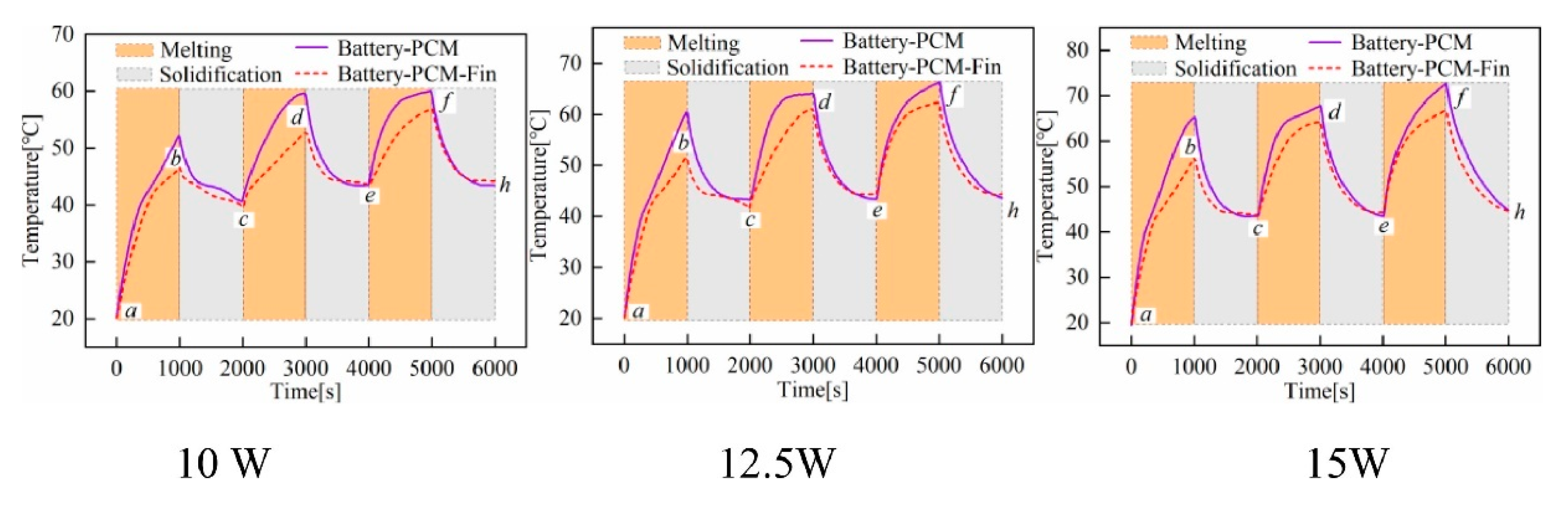
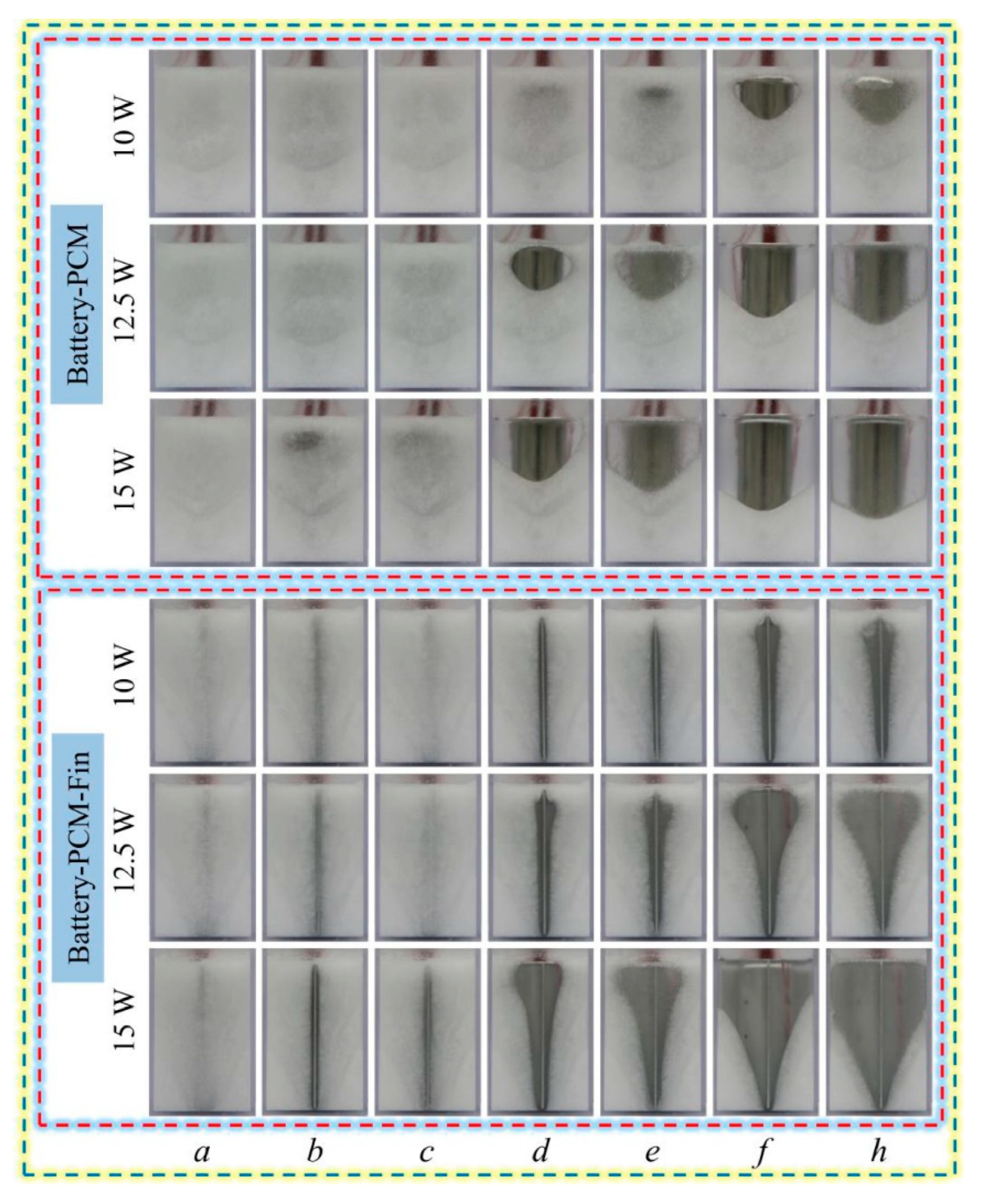
  66. Sun, Z.; Fan, R.; Zheng, N. Thermal management of a simulated battery with the compound use of phase change material and fins: Experimental and numerical investigations. Int. J. Therm. Sci. 2021, 165, 106945. [Google Scholar] [CrossRef]
  67. Shahsavar, A.; Goodarzi, A.; Askari, I.B.; Jamei, M.; Karbasi, M.; Afrand, M. The entropy generation analysis of the influence of using fins with tip clearance on the thermal management of the batteries with phase change material: Application a new gradient-based ensemble machine learning approach. Eng. Anal. Bound. Elem. 2022, 140, 432–446. [Google Scholar] [CrossRef]
  68. Qi, X.; Sidi, M.O.; Tlili, I.; Ibrahim, T.K.; Elkotb, M.A.; El-Shorbagy, M.A.; Li, Z. Optimization and sensitivity analysis of extended surfaces during melting and freezing of phase changing materials in cylindrical Lithium-ion battery cooling. J. Energy Storage 2022, 51, 104545. [Google Scholar] [CrossRef]
  69. Liu, Y.; Zheng, J.; Deng, Y.; Wu, F.; Wang, H. Effect of functional modification of porous medium on phase change behavior and heat storage characteristics of form-stable composite phase change materials: A critical review. J. Energy Storage 2021, 44, 103637. [Google Scholar] [CrossRef]
  70. Zhang, P.; Cui, Y.; Zhang, K.; Wu, S.; Chen, D.; Gao, Y. Enhanced thermal storage capacity of paraffin/diatomite composite using oleophobic modification. J. Clean. Prod. 2021, 279, 123211. [Google Scholar] [CrossRef]
  71. Cui, W.; Si, T.; Li, X.; Li, X.; Lu, L.; Ma, T.; Wang, Q. Heat transfer enhancement of phase change materials embedded with metal foam for thermal energy storage: A review. Renew. Sustain. Energy Rev. 2022, 169, 112912. [Google Scholar] [CrossRef]
  72. Situ, W.; Zhang, G.; Li, X.; Yang, X.; Wei, C.; Rao, M.; Wang, Z.; Wang, C.; Wu, W. A thermal management system for rectangular LiFePO4 battery module using novel double copper mesh-enhanced phase change material plates. Energy 2017, 141, 613–623. [Google Scholar] [CrossRef]
  73. Wu, W.; Yang, X.; Zhang, G.; Ke, X.; Wang, Z.; Situ, W.; Li, X.; Zhang, J. An experimental study of thermal management system using copper mesh-enhanced composite phase change materials for power battery pack. Energy 2016, 113, 909–916. [Google Scholar] [CrossRef]
  74. Zhao, Y.; Zou, B.; Ding, J.; Ding, Y. Experimental and numerical investigation of a hybrid battery thermal management system based on copper foam-paraffin composite phase change material and liquid cooling. Appl. Therm. Eng. 2023, 218, 119312. [Google Scholar] [CrossRef]
  75. Pan, M.; Zhong, Y. Experimental and numerical investigation of a thermal management system for a Li-ion battery pack using cutting copper fiber sintered skeleton/paraffin composite phase change materials. Int. J. Heat Mass Transf. 2018, 126, 531–543. [Google Scholar] [CrossRef]
  76. Alipanah, M.; Li, X. Numerical studies of lithium-ion battery thermal management systems using phase change materials and metal foams. Int. J. Heat Mass Transf. 2016, 102, 1159–1168. [Google Scholar] [CrossRef]
  77. Wang, Z.; Zhang, Z.; Jia, L.; Yang, L. Paraffin and paraffin/aluminum foam composite phase change material heat storage experimental study based on thermal management of Li-ion battery. Appl. Therm. Eng. 2015, 78, 428–436. [Google Scholar] [CrossRef]
  78. Heyhat, M.M.; Mousavi, S.; Siavashi, M. Battery thermal management with thermal energy storage composites of PCM, metal foam, fin and nanoparticle. J. Energy Storage 2020, 28, 101235. [Google Scholar] [CrossRef]
  79. Pandey, H.; Gupta, N.K. A descriptive review of the thermal transport mechanisms in mono and hybrid nanofluid-filled heat pipes and current developments. Therm. Sci. Eng. Prog. 2022, 31, 101281. [Google Scholar] [CrossRef]
  80. Muhammad Ali, H. Applications of combined/hybrid use of heat pipe and phase change materials in energy storage and cooling systems: A recent review. J. Energy Storage 2019, 26, 100986. [Google Scholar] [CrossRef]
  81. Boonma, K.; Patimaporntap, N.; Mbulu, H.; Trinuruk, P.; Ruangjirakit, K.; Laoonual, Y.; Wongwises, S. A Review of the Parameters Affecting a Heat Pipe Thermal Management System for Lithium-Ion Batteries. Energies 2022, 15, 8534. [Google Scholar] [CrossRef]
  82. Bernagozzi, M.; Georgoulas, A.; Miche, N.; Marengo, M. Heat pipes in battery thermal management systems for electric vehicles: A critical review. Appl. Therm. Eng. 2023, 219, 119495. [Google Scholar] [CrossRef]
  83. Karimi, D.; Behi, H.; Van Mierlo, J.; Berecibar, M. Novel Hybrid Thermal Management System for High-Power Lithium-Ion Module for Electric Vehicles: Fast Charging Applications. World Electr. Veh. J. 2022, 13, 86. [Google Scholar] [CrossRef]
  84. Putra, N.; Sandi, A.F.; Ariantara, B.; Abdullah, N.; Indra Mahlia, T.M. Performance of beeswax phase change material (PCM) and heat pipe as passive battery cooling system for electric vehicles. Case Stud. Therm. Eng. 2020, 21, 100655. [Google Scholar] [CrossRef]
  85. Hu, C.; Li, H.; Wang, Y.; Hu, X.; Tang, D. Experimental and numerical investigations of lithium-ion battery thermal management using flat heat pipe and phase change material. J. Energy Storage 2022, 55, 105743. [Google Scholar] [CrossRef]
  86. Zhao, J.; Lv, P.; Rao, Z. Experimental study on the thermal management performance of phase change material coupled with heat pipe for cylindrical power battery pack. Exp. Therm. Fluid Sci. 2017, 82, 182–188. [Google Scholar] [CrossRef]
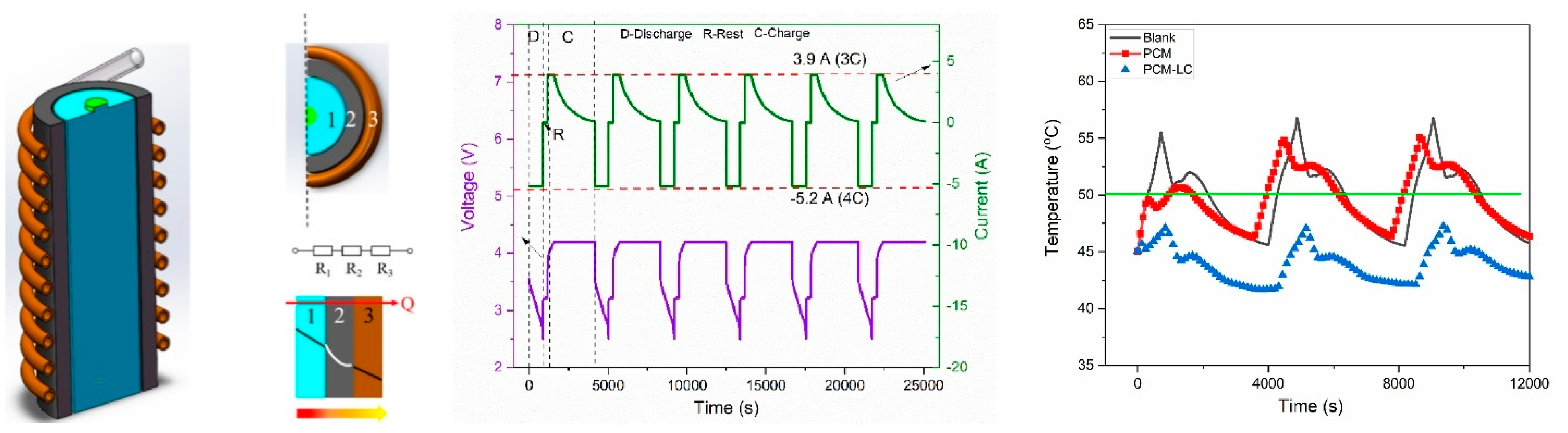
  87. Jiang, Z.Y.; Qu, Z.G. Lithium–ion battery thermal management using heat pipe and phase change material during discharge–charge cycle: A comprehensive numerical study. Appl. Energy 2019, 242, 378–392. [Google Scholar] [CrossRef]
  88. Tang, Z.; Feng, R.; Huang, P.; Bai, Z.; Wang, Q. Modeling analysis on the cooling efficiency of composite phase change material-heat pipe coupling system in battery pack. J. Loss Prev. Process. Ind. 2022, 78, 104829. [Google Scholar] [CrossRef]
  89. Peng, P.; Wang, Y.; Jiang, F. Numerical study of PCM thermal behavior of a novel PCM-heat pipe combined system for Li-ion battery thermal management. Appl. Therm. Eng. 2022, 209, 118293. [Google Scholar] [CrossRef]
  90. Feng, R.; Huang, P.; Tang, Z.; He, Y.; Bai, Z. Experimental and numerical study on the cooling performance of heat pipe assisted composite phase change material-based battery thermal management system. Energy Convers. Manag. 2022, 272, 116359. [Google Scholar] [CrossRef]
  91. Leng, Z.; Yuan, Y.; Cao, X.; Zhong, W.; Zeng, C. Heat pipe/phase change material coupled thermal management in Li-ion battery packs: Optimization and energy-saving assessment. Appl. Therm. Eng. 2022, 208, 118211. [Google Scholar] [CrossRef]
  92. Leng, Z.; Yuan, Y.; Cao, X.; Zeng, C.; Zhong, W.; Gao, B. Heat pipe/phase change material thermal management of Li-ion power battery packs: A numerical study on coupled heat transfer performance. Energy 2022, 240, 122754. [Google Scholar] [CrossRef]
  93. Septiadi, W.N.; Alim, M.; Pradipta Adi, M.N. The application of battery thermal management system based on heat pipes and phase change materials in the electric bike. J. Energy Storage 2022, 56, 106014. [Google Scholar] [CrossRef]
  94. Khademi, A.; Shank, K.; Mehrjardi, S.A.A.; Tiari, S.; Sorrentino, G.; Said, Z.; Chamkha, A.J.; Ushak, S. A brief review on different hybrid methods of enhancement within latent heat storage systems. J. Energy Storage 2022, 54, 105362. [Google Scholar] [CrossRef]
  95. Bianco, N.; Busielo, S.; Iasiello, M.; Maria Mauro, G. Finned heat sinks with phase change materials and metal foams: Pareto optimization to address cost and operation time. Appl. Therm. Eng. 2021, 197, 117436. [Google Scholar] [CrossRef]
  96. Huang, Y.; Sun, Q.; Yao, F.; Zhang, C. Experimental Study on the Thermal Performance of a Finned Metal Foam Heat Sink with Phase Change Material. Heat. Transf. Eng. 2021, 42, 579–591. [Google Scholar] [CrossRef]
  97. Keshteli, A.N.; Iasiello, M.; Langella, G.; Bianco, N. Enhancing PCMs thermal conductivity: A comparison among porous metal foams, nanoparticles and finned surfaces in triplex tube heat exchangers. Appl. Therm. Eng. 2022, 212, 118623. [Google Scholar] [CrossRef]
  98. Rahmanian, S.; Moein-Jahromi, M.; Rahmanian-Koushkaki, H.; Sopian, K. Performance investigation of inclined CPV system with composites of PCM, metal foam and nanoparticles. Sol. Energy 2021, 230, 883–901. [Google Scholar] [CrossRef]
  99. Li, F.; Muhammad, N.; Abohamzeh, E.; Hakeem, A.A.; Hajizadeh, M.R.; Li, Z.; Bach, Q.-V. Finned unit solidification with use of nanoparticles improved PCM. J. Mol. Liq. 2020, 314, 113659. [Google Scholar] [CrossRef]
  100. Wang, T.; Almarashi, A.; Al-Turki, Y.A.; Abu-Hamdeh, N.H.; Hajizadeh, M.R.; Chu, Y.-M. Approaches for expedition of discharging of PCM involving nanoparticles and radial fins. J. Mol. Liq. 2021, 329, 115052. [Google Scholar] [CrossRef]
  101. Weng, J.; Xiao, C.; Yang, X.; Ouyang, D.; Chen, M.; Zhang, G.; Waiming, E.L.; Kit Yuen, R.K.; Wang, J. An energy-saving battery thermal management strategy coupling tubular phase-change-material with dynamic liquid cooling under different ambient temperatures. Renew. Energy 2022, 195, 918–930. [Google Scholar] [CrossRef]
  102. Mousavi, S.; Zadehkabir, A.; Siavashi, M.; Yang, X. An improved hybrid thermal management system for prismatic Li-ion batteries integrated with mini-channel and phase change materials. Appl. Energy 2023, 334, 120643. [Google Scholar] [CrossRef]
  103. Hekmat, S.; Bamdezh, M.A.; Molaeimanesh, G.R. Hybrid thermal management for achieving extremely uniform temperature distribution in a lithium battery module with phase change material and liquid cooling channels. J. Energy Storage 2022, 50, 104272. [Google Scholar] [CrossRef]
  104. Singh, L.K.; Gupta, A.K.; Sharma, A.K. Hybrid thermal management system for a lithium-ion battery module: Effect of cell arrangement, discharge rate, phase change material thickness and air velocity. J. Energy Storage 2022, 52, 104907. [Google Scholar] [CrossRef]
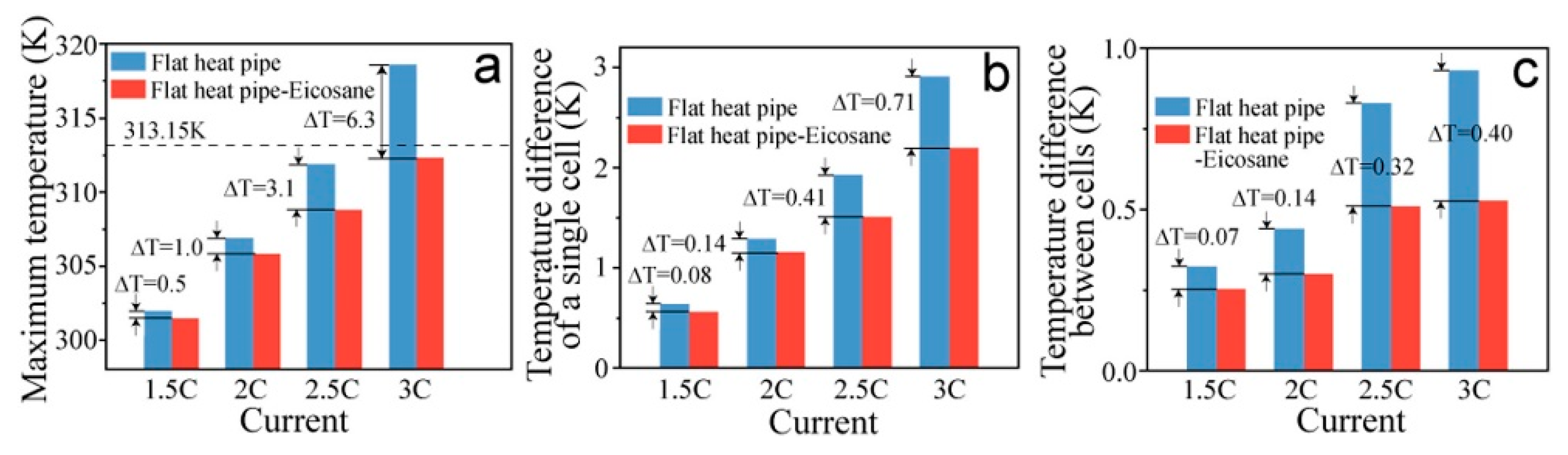
  105. Abbas, S.; Ramadan, Z.; Park, C.W. Thermal performance analysis of compact-type simulative battery module with paraffin as phase-change material and flat plate heat pipe. Int. J. Heat Mass Transf. 2021, 173, 121269. [Google Scholar] [CrossRef]
  106. Liu, X.; Zhang, C.-F.; Zhou, J.-G.; Xiong, X.; Wang, Y.-P. Thermal performance of battery thermal management system using fins to enhance the combination of thermoelectric Cooler and phase change Material. Appl. Energy 2022, 322, 119503. [Google Scholar] [CrossRef]
  107. Gharehghani, A.; Gholami, J.; Shamsizadeh, P.; Mehranfar, S. Effect analysis on performance improvement of battery thermal management in cold weather. J. Energy Storage 2022, 45, 103728. [Google Scholar] [CrossRef]
  108. Xie, P.; Jin, L.; Qiao, G.; Lin, C.; Barreneche, C.; Ding, Y. Thermal energy storage for electric vehicles at low temperatures: Concepts, systems, devices and materials. Renew. Sustain. Energy Rev. 2022, 160, 112263. [Google Scholar] [CrossRef]
  109. Henry, A.; Prasher, R.; Majumdar, A. Five thermal energy grand challenges for decarbonization. Nat. Energy 2020, 5, 635–637. [Google Scholar] [CrossRef]
  110. Lau, J.; Papp, J.K.; Lilley, D.; Khomein, P.; Kaur, S.; Dames, C.; Liu, G.; Prasher, R. Dynamic tunability of phase-change material transition temperatures using ions for thermal energy storage. Cell Rep. Phys. Sci. 2021, 2, 100613. [Google Scholar] [CrossRef]
  111. Wu, Y.; Zhang, X.; Xu, X.; Lin, X.; Liu, L. A review on the effect of external fields on solidification, melting and heat transfer enhancement of phase change materials. J. Energy Storage 2020, 31, 101567. [Google Scholar] [CrossRef]
  112. Dai, R.; Wu, Y.; Mostaghimi, J.; Tang, L.; Zeng, M. Characteristics and control mechanism of melting process under extra magnetic force fields. Appl. Therm. Eng. 2020, 167, 114704. [Google Scholar] [CrossRef]
  113. Mehryan, S.A.M.; Tahmasebi, A.; Izadi, M.; Ghalambaz, M. Melting behavior of phase change materials in the presence of a non-uniform magnetic-field due to two variable magnetic sources. Int. J. Heat Mass Transf. 2020, 149, 119184. [Google Scholar] [CrossRef]
  114. Kumar, A.; Saha, S.K.; Kumar, K.R.; Rakshit, D. Study of melting of paraffin dispersed with copper nanoparticles in square cavity subjected to external magnetic field. J. Energy Storage 2022, 50, 104338. [Google Scholar] [CrossRef]
  115. Xu, W.; Huang, T.; Huang, S.-M.; Zhuang, Y. Regulation mechanism of magnetic field on non-Newtonian melting and energy storage performance of metal foam composite nano-enhanced phase change materials. Int. J. Heat Mass Transf. 2023, 200, 123501. [Google Scholar] [CrossRef]
  116. Sun, Z.; Yang, P.; Luo, K.; Wu, J. Experimental investigation on the melting characteristics of n-octadecane with electric field inside macrocapsule. Int. J. Heat Mass Transf. 2021, 173, 121238. [Google Scholar] [CrossRef]
  117. Sun, Z.; Zhang, Y.; Luo, K.; Perez, A.T.; Yi, H.; Wu, J. Experimental investigation on melting heat transfer of an organic material under electric field. Exp. Therm. Fluid Sci. 2022, 131, 110530. [Google Scholar] [CrossRef]
  118. Sun, Z.; Luo, K.; Wu, J. Experimental study on the melting characteristics of n-octadecane with passively installing fin and actively applying electric field. Int. Commun. Heat Mass Transf. 2021, 127, 105570. [Google Scholar] [CrossRef]
  119. Zhou, W.; Mohammed, H.I.; Chen, S.; Luo, M.; Wu, Y. Effects of mechanical vibration on the heat transfer performance of shell-and-tube latent heat thermal storage units during charging process. App. Therm. Eng. 2022, 216, 119133. [Google Scholar] [CrossRef]
  120. Zhang, W.; Li, X.; Wu, W.; Huang, J. Influence of mechanical vibration on composite phase change material based thermal management system for lithium-ion battery. J. Energy Storage 2022, 54, 105237. [Google Scholar] [CrossRef]
  121. Joshy, N.; Hajiyan, M.; Siddique, A.R.M.; Tasnim, S.; Simha, H.; Mahmud, S. Experimental investigation of the effect of vibration on phase change material (PCM) based battery thermal management system. J. Power Sources 2020, 450, 227717. [Google Scholar] [CrossRef]
Figure 1. The volume-averaged battery temperature as a function of EG mass fraction.
Energies 16 02745 g001
Figure 2. Li-ion battery packs: (a)—60 wt% RT44HC/EG; (b)—60 wt% RT44HC/fumed silica; (c)—no PCM. Reproduced from [34] with permission from Elsevier.
Energies 16 02745 g002
Figure 3. Temperature distribution of the Li-ion battery pack for discharge rates 0.5C, 1C, 1.5C and 2C at −10 °C: (a) with RT44HC/EG composite; (b) without PCM. Reproduced from [34] with permission from Elsevier.
Energies 16 02745 g003
Figure 4. The preparation procedure of the Flexible Composite PCM (FCPCM) [35]. Reproduced with permission from Elsevier.
Energies 16 02745 g004
Figure 5. The experimental set up described in [35]. Reproduced with permission from Elsevier.
Energies 16 02745 g005
Figure 6. (Left): The synthesis process of the composite PCM [43]; (Right): Thermal conductivity of the composite PCM as a function of EG/PW ratio. Reproduced with permission from Elsevier.
Energies 16 02745 g006
Figure 7. Maximum temperature difference between the simulator surface and the composite PCM [46]. Reproduced with permission from Elsevier.
Energies 16 02745 g007
Figure 8. (top) The BTMS with two different PCMs described in [48] with trans-radial (left) and trans-axial (middle, right) arrangement. (bottom): The LF versus time for the three layouts: (a) trans-radial; (b) trans-axial. Reproduced with permission from Elsevier.
Energies 16 02745 g008aEnergies 16 02745 g008b
Figure 9. Battery cell surface temperature during cycling test [54]. Reproduced with permission from Elsevier.
Energies 16 02745 g009
Figure 10. Visualization of the phase transition process during thermal cycling [54] (images a to h were taken at the beginning/end of each of the six segments in Figure 9). Reproduced with permission from Elsevier.
Energies 16 02745 g010
Figure 11. Fin layouts considered in [54]. (B) baseline layout, (1) (2) (3) (4) different fin layouts.
Energies 16 02745 g011
Figure 12. Numerical simulation of the temperature field (a) and liquid fraction (b) for the fin layouts presented in Figure 11. Reproduced from [54] with permission from Elsevier.
Energies 16 02745 g012
Figure 13. The experimental set up discussed in [55]: (a) functional diagram; (b) cross-section of the battery pack showing the 24 cells (numbered from 1 to 24); (c) battery pack coupling with the heat dissipation fins. Reproduced with permission from Elsevier.
Energies 16 02745 g013
Figure 14. The dual active-passive BTMS system [56]. (a) Components and connections; (b) Container with the battery; (c) Aluminum poles used to drive the fins. Reproduced with permission from Elsevier.
Energies 16 02745 g014
Figure 15. The combined shape fins proposed in [65]: (a) configuration of the BTMS with fins and PCM; (b) locations of the temperature measurement sensors. d * —dimensionless distance of the ring, defined as the ratio of the radial distance of the ring to that of the diameter of the battery. Reproduced with permission from Elsevier.
Energies 16 02745 g015
Figure 16. Temperature and LF distribution for one and two cylindrical rings [65]. Reproduced with permission from Elsevier.
Energies 16 02745 g016
Figure 17. The setup considered in [67]. Reproduced with permission from Elsevier.
Energies 16 02745 g017
Figure 18. The PCM-fins BTMS considered in [68]. Reproduced with permission from Elsevier.
Energies 16 02745 g018
Figure 19. (a) Image of the physical set up; (b) schematic diagram of the battery system; (c) detail view of the copper mesh placement [72] (left) and the thermal conductivity of the composite structures (right). Reproduced with permission from Elsevier.
Energies 16 02745 g019
Figure 20. The temperature evolution in the battery module for discharging rates (a) 1C, (b) 3C and (c) 5C [72]. Reproduced with permission from Elsevier.
Energies 16 02745 g020
Figure 21. The hybrid active-passive BTMS described in [74]. (a) the Cu MF and the cooling pipes embedded into it—top view; (b) same as (a), front view; (c) PCM-impregnated Cu foam; (d) BTMS with insulation applied.
Energies 16 02745 g021
Figure 22. The composite Cu foam—PCM samples discussed in [75]. Reproduced with permission from Elsevier.
Energies 16 02745 g022
Figure 23. (Left): the BTMS described in [84]; (Right): Battery surface temperature for various BTMS investigated in [84] for heat dissipation rate 60 W.
Energies 16 02745 g023
Figure 24. The physical system described in [85] consisting of eight rectangular cells (numbered from I to VIII, aligned with alternating gaps). (a) HP BTMS; (b) HP-PCM BTMS. Reproduced with permission from Elsevier.
Energies 16 02745 g024
Figure 25. (a) Maximum temperature of the battery pack; (b) Temperature difference of a single cell; (c) Temperature difference of all cells [85]. Reproduced with permission from Elsevier.
Energies 16 02745 g025
Figure 26. (Left): The hybrid BTMS described in [101]; (Middle): thermal cycling load; (Right): Battery temperature. Reproduced with permission from Elsevier.
Energies 16 02745 g026
Figure 27. (Left): The volumetric battery heat generation rate (WLTP class 3 at T = 298.15 K); (Middle): Maximum battery temperature; (Right): Temperature difference and PCM LF for the hybrid BTMS with three PCM plates and active BTMS in a driving cycle. Reproduced from [102] with permission from Elsevier.
Energies 16 02745 g027
Figure 28. BTMS 1—passive, PCM only; BTMS 2—active cooling, parallel flow; BTMS 3—active cooling, counter flow. Reproduced from [103] with permission from Elsevier.
Energies 16 02745 g028
Figure 29. (a)—Detached Heat Pipe (DHP) system; (b)—Attached Heat Pipe (AHP) system [105]. Reproduced with permission from Elsevier.
Energies 16 02745 g029
Figure 30. Experiment (visualization) and simulation (top) for the AHP system; Experiment (visualization) for the DHP system (bottom) [105]. Reproduced with permission from Elsevier.
Energies 16 02745 g030
Figure 31. (Left): The hybrid BTMS with fins, TEC and PCM: (a) the battery cell; (b) the PCM; (c) thermoelectric cooler; (d) metallic fin; (e) liquid cooling plate; Middle: The battery temperature (no fins versus 4 mm fins); (Right): The temperature difference. Reproduced from [106] with permission from Elsevier.
Energies 16 02745 g031
Figure 32. The physical system investigated in [112]. Reproduced with permission from Elsevier.
Energies 16 02745 g032
Figure 33. (a) The functional diagram; (b) enclosure with fin; (c) enclosure without fin. Reproduced from [118] with permission from Elsevier.
Energies 16 02745 g033
Table 1. Advantages and disadvantages of organic and inorganic PCMs.
PCMAdvantagesDisadvantages
OrganicsHigh latent heat
No phase segregation
Chemical stability
Self-nucleate
Extended MP range
Compatible with most materials
Recyclable
Low-vapor pressure
Flammable
Limited availability
Limited biodegradability
Significant volume change during phase transition
Low thermal conductivity
Low volumetric latent heat
InorganicsNon-flammable
High thermal conductivity
Phase transition over a very narrow temperature range
High volumetric latent heat
Low-volume change during phase transition
Tendency to undergo supercooling
Corrosive
May require nucleating and thickening agents
Phase segregation
EutecticsHigh volumetric latent heat
Phase transition over a very narrow temperature range
Properties can be modulated to match the application requirements
High cost
Limited data on thermos-physical properties
Table 2. PCM thermal conductivity enhancement with additives for BTMS. Experimental studies.
RefPCMAdditiveBattery systemMethods/PreparationResults
Goli et al. [36] Paraffin IGI-1260Graphene with flake thickness 0.35, 1 and 8 nmSix 4-V Li-ion cells with the capacity 3000 mAh eachDispersing a solution of the liquid-phase exfoliated graphene and few-layer graphene (FLG) in the paraffin wax at 70 °C followed by the high-shear mixing on a hot plateThe maximum temperature increase during charging/discharging (at 16 and 5 A) cycle dropped from ~37 °C (no PCM) to 23 °C (pure PCM), 17 °C (PCM and Graphene, 1 nm) and 14 °C (PCM and Graphene 0.35 nm)
Wang et al. [37] Paraffin with MP 48–50 °CGraphite powder with mass fraction 2.5%, 5%, 10%, 20%
Nickel foam
LiFePO4, capacity 80 Ah, nominal voltage 3.2 VThe graphite powder was added when the PCM was completely melted into liquid. Then, the mixture was stirred continuously for 1 h by magnetic stirrer.The charging and discharging performance of LiFePO4 battery was less sensitive to high-temperature environment, but more sensitive to low-temperature environment. Both binary and ternary composites ensured that the lithium-ion battery with the initial temperature of 28℃ can charge and discharge normally without preheating after standing in the environment of −20℃ for less than 40 min.
Yang et al. [38] SAT with MP 58.4 °CCarbon foam
Polyurethane
Copper foam
Nano Al2O3
Li-ion, 3.85 V, 4590 mAhSAT was added to a flask held in an oil bath maintained at 110 °C. The flask was stirred and heated for 10 min. Next, DHPD was added to the flask, and the mixture was stirred and heated for. Al nanoparticles and CMC were added. Stirring was performed at 1100 r/min.The composite PCM achieved a dual modulation of the high enthalpy in the CPCM and carbon material-enhanced heat transfer for the intelligent and stable long-term operation of the BTMS.
Zhao et al. [39] OBC
DA
Graphite powder LiFePO4, 50 Ah, 3.2 VDA and OBC were milled into fine powders. The mixtures were placed into a customized mold and heated up in an oven at 200 °C for 1 h. The molds and mixtures were removed from the oven and cooled in the air. The CPCM plates were cut into cuboids with a dimension of 240 × 160 × 3 mm (which has the same size as the battery in length and width).Thermal conductivity increased 8–18 times compared to pure PCM.
Tested in a pack level, a maximum of 15 °C temperature reduction was achieved. compared to a high ambient temperature of 55 °C.
Thermal conductivity increased 8 to 18 times.
Zhou et al. [40] Paraffin with MP 50 °CEG
Melamine
LiFePO4, 20 Ah, 3.2 V95 wt% paraffin and 5 wt% EG were put into an oil bath at 80 °C. Molten paraffin and EG were stirred uniformly at 800 rad/min.Thermal conductivity increased from 0.21 W/m-K (pure PCM) to 0.85 (95% PCM + 5%EG) and 0.73 W/m-K (92% PCM + 5% EG + 3% Melamine).
Latent heat decreased when EG and Melamine were added.
Behi et al. [41] Paraffin with MP 35–42 °CGraphiteLi-ion, 18,650 cells, 2200 mAhBattery modules (24) were immersed in the molten PCM contained in a PVC rectangular box. The arrangement was 4 rows each with six modules, 2 mm spacing between modulesAdding graphite increased the thermal conductivity of the PCM from 0.25–0.4 to 0.5–1 W/m-K. The maximum temperature without PCM was 64 °C. Pure PCM and PCM-graphite reduced the battery temperature to 40 and 39 °C. PCM-graphite increased the uniformity of the temperature distribution.
Zhang et al. [42] Paraffin with MP 35–40 °CEG with mean particle size 150 mmLi-ion 42110, 10 Ah, 3.2 V, connected 15S1PParaffin was heated to 80°C. EG was added to molten paraffin at a mass ratio of 4:1 with continuous mechanical stirring. A composite PCM module was fabricated through the hot-compaction process in a rectangular mold.The TC of the composite increased 12 times compared to pure PCM.
In extreme 10.0C pulse discharge rate, peak temperature is always controlled within 50 °C. The latent heat of the PA/EG composite was 147.61 kJ/kg, which was 35.9% lower than that
of pure PCM. The MP of the composite decreased.
Table 3. Fin shapes and layouts for PCM-based BTMSs.
RefBattery Effects/Type of StudyFin Geometry/Layout
Ping et al. [57]LiFePO4, 10 AhThe PCM-fin structure resulted in the lowest temperature and the best temperature uniformity than other cooling cases. Decreasing fin thickness reduced the maximum temperature and temperature difference of battery module by increasing the heat exchange area with PCM. Fins with excessively small spacing have a negative influence by decreasing the PCM volume, which could be more significant than the positive effect of increasing the heat transfer area.
Numerical study
Energies 16 02745 i001
Chen et al. [58]LiPF6Annular parallel fins, cylindrical battery cell with vertical axis. The whole assembly immersed in the PCM.
The fin number was varied to identify the optimum number. The best performance in reducing the temperature was found for 9 fins. Beyond this number, the fins fail to reduce further the battery temperature. This effect was attributed to inhibiting the buoyancy-driven circulation during the PCM molten phase.
Numerical study
Energies 16 02745 i002
Fan et al. [59]18,650 Li-ion, 2.6 AhTriply periodic minimal surface (TPMS) P type and IWP type were used. (a)—PCM only; (b)—Kelvin type lattice; (c)—P type TPMS; (d)—P-IWP type TPMS. The melting time of the PCM in the case of P-IWP type TPMS reduced by 30.8% of that in the case of P type TPMS. At 1C discharge rate, the temperature in the case of P-IWP type TPMS decreases by 12.2% of that in the case of PCM-only. At 2C, the PCM completely melted in the case of P-IWP type TPMS due to the local heat transfer enhancement of the IWP type TPMS sheet structure with smaller lattice.
Numerical study
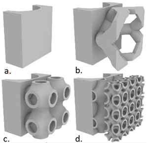
Energies 16 02745 i003
Mei et al. [60]18,650 Li-ion, 2.6 AhBy using EG-enhanced PCM and fins, the battery temperature was reduced by 35.5%. This effect was less significant as the environment temperature increased.
Experimental study
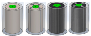
Energies 16 02745 i004
Choudhari et al. [61]18,650 Li-ion, 2.4 AhPCM module containing 4 fins exhibit optimum performance. This optimum fin structure resulted in a temperature drop of 2 °C and 6.1 °C (at 2C and 3C, respectively). No significant difference in heat transfer enhancement was observed. Numerical studyEnergies 16 02745 i005
Energies 16 02745 i006
(a)
Rectangular fins
(b)
Trapezoidal fins
(c)
Triangular fins
(d)
I-shaped fins
(e)
T-shaped fins
Choudhari et al. [62]18,650 Li-ion, 2.2 Ah. Connection 5S5PFin structure layout Type III, was the most effective in dissipating the heat stored at the inner cells of the battery pack without affecting significantly the outer cell temperature and melting time. Type III layout produced a more uniform temperature distribution.
At lower values of the natural convection heat transfer coefficient, fins are ineffective and the thermal performance is comparable to that of the no-fin case. The battery average temperature was reduced by 19.79 °C and the melting fraction by 66% when the heat transfer coefficient increased from 5 to 25 W/m2K.
Numerical study
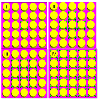
Energies 16 02745 i007
Weng et al. [63]INR18650–25R, 2500 mAhLongitudinal fins are more effective on heat dissipation by air convection, while circular fins show a stronger heat conduction ability inside the PCM medium due to their larger heat transfer area. The heat dissipation effect was more significant when the air convection coefficient increased. Increasing the longitudinal fin number, heat dissipation, was more intense; however, in a limited-space module, increasing fins does not necessarily mean an increase in fin efficiency. The optimum number of longitudinal fins was 4, resulting in a temperature drop from 36.9 to 34.2 °C in the rectangular finned module. Circular fins providing stronger heat conduction capability were inserted in the lower section, while rectangular fins were applied in the upper section. Considering both the limited space and efficiency, the number of rectangular and circular fins was set as 4 and 2.
Numerical study
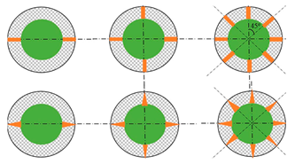
Energies 16 02745 i008
Energies 16 02745 i009
Liu et al. [64]LiCoO2
7000 mAh
3.8 V
The PCM cooling system with a honeycomb fin could maintain the battery temperature below 50 °C. Compared with the non-fin cooling system, the temperature drop of the system with honeycomb fin increased by 61%. The non-fin PCM cooling system melted completely at the bottom, and the energy was concentrated adjacent to the heat source. The honeycomb fin could distribute evenly the heat of the PCM in the vertical direction, and the PCM with different thicknesses began melting almost simultaneously, thereby optimizing the heat absorption effect of the PCM. Experimental study
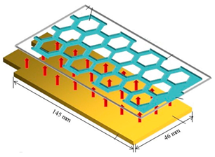
Energies 16 02745 i010
Table 4. PCM-based BTMSs with HPs for thermal performance enhancement.
ReferenceBTMS DescriptionHP/PCM Layout
Zhao et al. [86]Cylindrical battery cells in an inline arrangement with equal gaps between.
The cells assembly was immersed in a composite PCM (paraffin/EG with mass ratio 5, 10, 15 and 20%) filled container. The composite PCM MP was 39 °C.
Circular HP (start-up temperature 30 °C) with annular parallel fins attached to the condenser section. HPs immersed vertically in the PCM. In horizontal plane, the HPs arrangement layout was with each HP at equal distance from the four neighboring battery cells.
Energies 16 02745 i011
Jiang et al. [87]Layered structure consisting of a (1) prismatic battery cell 3.2 V, 8 Ah, (2) a Cu plate with two horizontal flat HP attached (3) an EG-PCM layer.
Two EG-PCM composites were developed with the MP 48 and 30 °C and thermal conductivity 2.4 and 2.5 W/m-K.
Flat HPs with the evaporator section attached continuously to the Cu plate over the whole plate length. Fins attached to the HP condenser section (HP axis perpendicular on the fins planes).
Energies 16 02745 i012
Tang et al. [88]Six cylindrical battery cells (4 Ah) equally spaced forming an array. Cells immersed in a PCM.
Three cell arrays placed next to each other with flat HPs separating them along the whole array length.
Flat HPs with the evaporator section separating the cell arrays. Condenser section extended vertically and cooling naturally.
Energies 16 02745 i013
Peng et al. [89]Cylindrical 18650 battery cells (40) in a 4 × 10 matrix arrangement with no gap between them. The voids were filled alternately with paraffin wax and circular HPs with annular parallel fins attached to the condenser section.
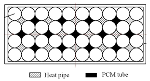
Energies 16 02745 i014
Energies 16 02745 i015
Feng et al. [90]3P × 6S INR21700 battery cells (4000 mAh). The battery cells in a group ox six were embedded in a composite PCM (paraffin—Cu MF).
Each group of six cells was separated from the next by a flat heat pipe (operating at 32 °C). Fins were applied to the upper section of the flat HP.
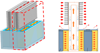
Energies 16 02745 i016
Leng et al. [91]55 Ah battery pack consisting of rectangular cells arranged parallelly.
All spaces between cells were filled with a composite PCM (paraffin/EG).
Flat HPs were used with the width equal to the distance between two cells, oriented vertically with finned condenser section. HP evaporator section fully immersed in the composite PCM.
Four HPs were inserted in each space.
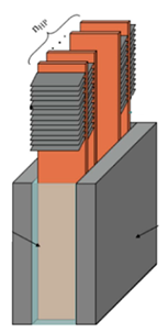
Energies 16 02745 i017
Leng et al. [92]Rectangular cells arranged parallelly, equally distanced.
The space between cells was filled with PCM.
Flat HPs were used with the width equal to the distance between two cells, oriented vertically with finned condenser section.
Two HPs were inserted in each inter-cell space with a common fin system.
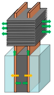
Energies 16 02745 i018
Septiadi et al. [93]13 × 4 18,650 Li-ion batteries embedded in a composite PCM (paraffin with MP 42 °C + EG 10%, 20% and 30% mass fraction values). Evaporator section of the HPs embedded in the CPCM. Finned heat sink on the condenser HP section.Energies 16 02745 i019
Disclaimer/Publisher’s Note: The statements, opinions and data contained in all publications are solely those of the individual author(s) and contributor(s) and not of MDPI and/or the editor(s). MDPI and/or the editor(s) disclaim responsibility for any injury to people or property resulting from any ideas, methods, instructions or products referred to in the content.

