Article

Study of the Wellbore Instability Mechanism of Shale in the Jidong Oilfield under the Action of Fluid

1
Institute of Drilling and Production Technology, Petro China Jidong Oilfield Company, Tangshan 063000, China
2
School of Petroleum Engineering, Northeast Petroleum University, Daqing 163318, China
*
Author to whom correspondence should be addressed.
Energies 2023, 16(7), 2989; https://doi.org/10.3390/en16072989
Submission received: 28 August 2022 / Revised: 30 September 2022 / Accepted: 25 November 2022 / Published: 24 March 2023

Abstract

:
Wellbore instability is the primary technical problem that restricts the low-cost drilling of long-interval horizontal wells in the shale formation of the Jidong Oilfield. Based on the evaluation of the mineral composition, structure and physicochemical properties of shale, this paper investigates the mechanical behavior and instability characteristics of shale under fluid action by combining theoretical analysis, experimental evaluation and numerical simulation. Due to the existence of shale bedding and microcracks, the strength of shale deteriorates after soaking in drilling fluid. The conductivity of the weak surface of shale is much higher than that of the rock matrix. The penetration of drilling fluid into the formation along the weak surface directly reduces the strength of the structural surface of shale, which is prone to wellbore collapse. The collapse pressure of the shale formation in the Nanpu block of the Jidong oilfield was calculated. The well inclination angle, azimuth angle and drilling fluid soaking time were substituted in the deterioration model of rock mechanics parameters, and the safe drilling fluid density of the target layer was given. This work has important guiding significance for realizing wellbore stability and safe drilling of hard brittle shale in the Jidong Oilfield.

1. Introduction

The wellbore instability of shale has always been a complex problem in drilling engineering worldwide. Borehole wall instability causes great difficulties in drilling engineering, mainly manifested as diameter reduction and collapse sticking. These problems not only prolong the drilling cycle but also increase the drilling cost [1,2,3]. Borehole instability is due to the bedding development and strong water sensitivity of shale. The invasion of drilling fluid causes fractures to continuously extend and expand along the formation, eventually forming a complex fracture network. This greatly reduces rock strength [4,5]. The integrity of near-wellbore water content and cementation changes the formation strength and stress field around a borehole, causing stress concentration and failure to establish a new equilibrium in the borehole, resulting in borehole instability [6,7].
Current research on the wellbore stability of shale focuses on the mechanical–chemical–thermal coupling of multiple fields and is basically in the preliminary research stage [8,9]. However, whether the strength of layered shale under the action of fluid changes with the action time and the influence of strength deterioration on the collapse pressure of well walls remains ambiguous [10,11]. The outstanding feature of the shale formation in the Jidong Oilfield is that it has approximately parallel bedding planes, that is, the dividing planes between rock layers. Bedding is different from microcrack with no obvious displacement, and the strength of the rock affected by the bedding plane has stronger anisotropy. In this paper, laboratory experiments are carried out on the bedded shale in the Nanpu block of Jidong Oilfield. The hydration of shale is analyzed by the finite difference method and numerical simulation, and the degradation mechanism of the shale in the lower layer is revealed. This research has guiding significance in the design of drilling fluids for shale formations and for realizing high-quality, safe, efficient and low-cost drilling.

2. Experiment on Mineral Composition and Mechanical Parameters of Bedded Shale

In order to study the degradation law of shale under the action of different fluids, cores from Well NP2-46 in the Jidong Oilfield were selected for laboratory experiments. The core was taken by pressure maintaining coring on site and sealed with heat-shrinkable tube to prevent it from drying. Because the bedding and fracture of the shale are obviously developed, the wire-cutting method was adopted to conduct secondary sampling for the core, which ensures that the rock sample does not contact any fluid during processing. This ensures that the experimental results accurately reflect the real situation in the well.

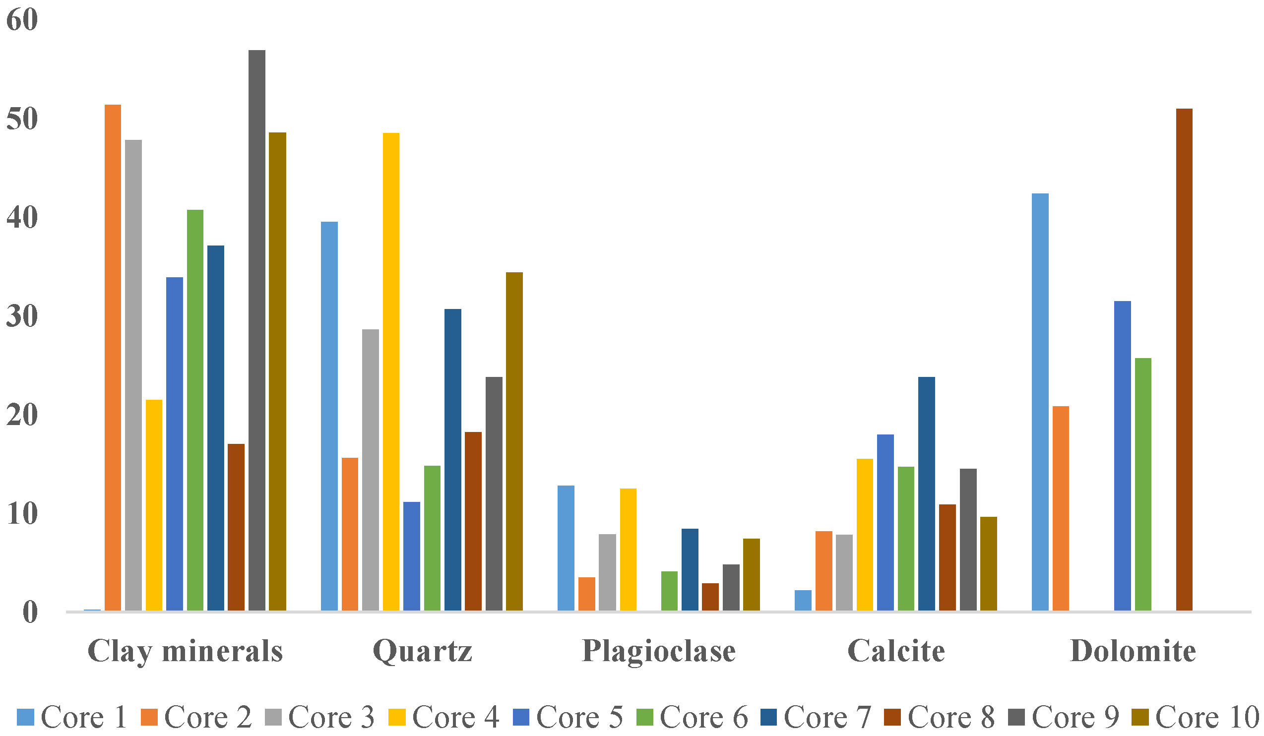
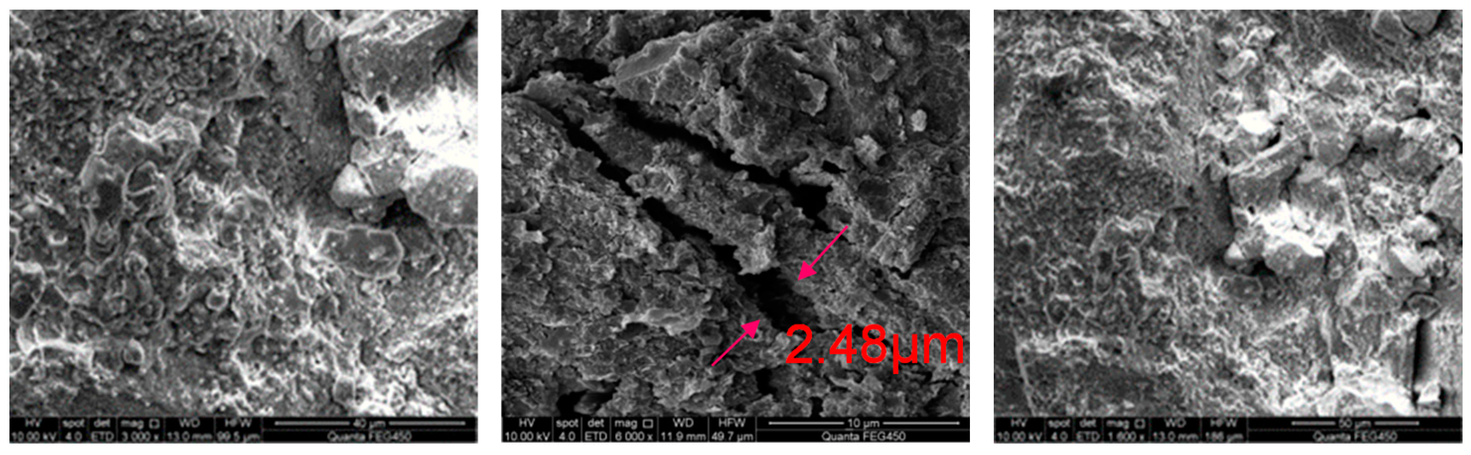
2.1. Mineral Composition and Fracture Development Characteristics

X-ray diffraction (X-RD) and scanning electron microscopy experiments were carried out on the shale in the Nanpu block of Jidong Oilfield. Figure 1 shows the X-RD experimental test results. It can be seen from the figure that the main mineral components of the shale are clay and quartz minerals. Minerals with extremely poor expansiveness, such as quartz, are attached to the surrounding of the clay. After the clay is hydrated and expanded under the action of the drilling fluid, a pressure difference is generated, which leads to the instability of the shale. In addition, hard and brittle minerals such as plagioclase, calcite and dolomite are developed to different degrees. The average content of clay minerals is 34.85%. The clay minerals mainly consist of illite and illite-mixed layers, followed by kaolinite and chlorite without montmorillonite. The illite content is higher in the illite-mixed layer, which also shows the typical brittleness characteristics of deep shale in the structure. This kind of lithology is not easy to expand, but the illite in it also undergoes rapid microexpansion. This is due to the adsorption of water molecules on illite, which leads to the surface hydration of rocks, and the main driving force is the surface hydration energy. This reduces the strength of the shale and causes its spalling.
The shale in the Nanpu block is mainly argillaceous, with a compact and hard structure. Figure 2 shows the observation results of scanning electron microscopy. It can be found that the pores in the shale are not developed, and the micro pores are scattered, but the microfractures and micropores are relatively developed. There is no typical occurrence of minerals and clay minerals in the core. The fracture width in the SEM image is 2.48 μm. When shale is placed in water, a large number of small air bubbles are attached to the surface of the shale. Over time, obvious cracks appeared in the rock sample, which gradually opened and finally collapsed.

2.2. Triaxial Compressive Strength Test of Shale

Due to the significant anisotropy of bedded shale, coring was carried out along different bedding angles. The samples were then machined into standard core columns with a diameter of 25 mm and a length of 50 mm for triaxial compressive strength testing of the shale in an unimmersed state. Figure 3 shows the fracture patterns of the core after loading in the parallel and vertical bedding directions.
According to the photos of rock breakage, the fracture morphology of parallel and vertical stratified rocks is different after loading. When loading is parallel to the direction of stratification, multiple openings occur along the bedding cracks, forming multiple groups of fragments along the direction of the bedding plane. However, shear cracks are generated when the vertical bedding direction is loaded, and large volume fractures are formed after the shear cracks connect with the microcracks along the bedding. Rock loaded in the parallel bedding direction produces tensile failure along the structural plane, and rock loaded in the vertical bedding direction needs to overcome the shear strength of the shale body.
Table 1 shows the experimental test results. The strength of the shale under parallel bedding and vertical bedding loading is very different, and the anisotropy is strong. When the confining pressure is set to 60 MPa, the elastic modulus of the shale loaded by vertical bedding is high and the Poisson ratio is low, indicating that the shale in the Nanpu block is relatively brittle.
Due to the well-developed bedding and significant anisotropy of the shale, the compressive strength experiments under loading at angles of 30°, 45° and 60° with the bedding were continued. Combined with the above triaxial compressive strength test results loaded in the parallel and vertical bedding directions, the cohesive force and internal friction angle of the rock were calculated as shown in Table 2.
According to the analysis of the triaxial stress experimental results in different loading directions, the failure of the shale can be divided into three regions, as shown in Figure 4. When the loading direction is perpendicular to the shale bedding, the strength is the highest, and with the increase in the included angle, the strength gradually decreases. According to Mohr–Coulomb criterion, when the angle is 45° + φ/2 (φ is the angle of internal friction), the intensity reaches the lowest value and then gradually increases.
According to the different loading directions, shale failure forms can be expressed as follows:
(1)
When the loading direction is 0°~30° to the bedding, splitting failure mainly occurs along the bedding plane.
(2)
Shear slip mainly occurs along the bedding plane when the loading direction is between 30° and 75°, and the strength is the lowest between 50° and 60°.
(3)
When the loading direction is in the range of 75°~90° with bedding, shear failure of the shale body mainly occurs, and the strength is the largest.

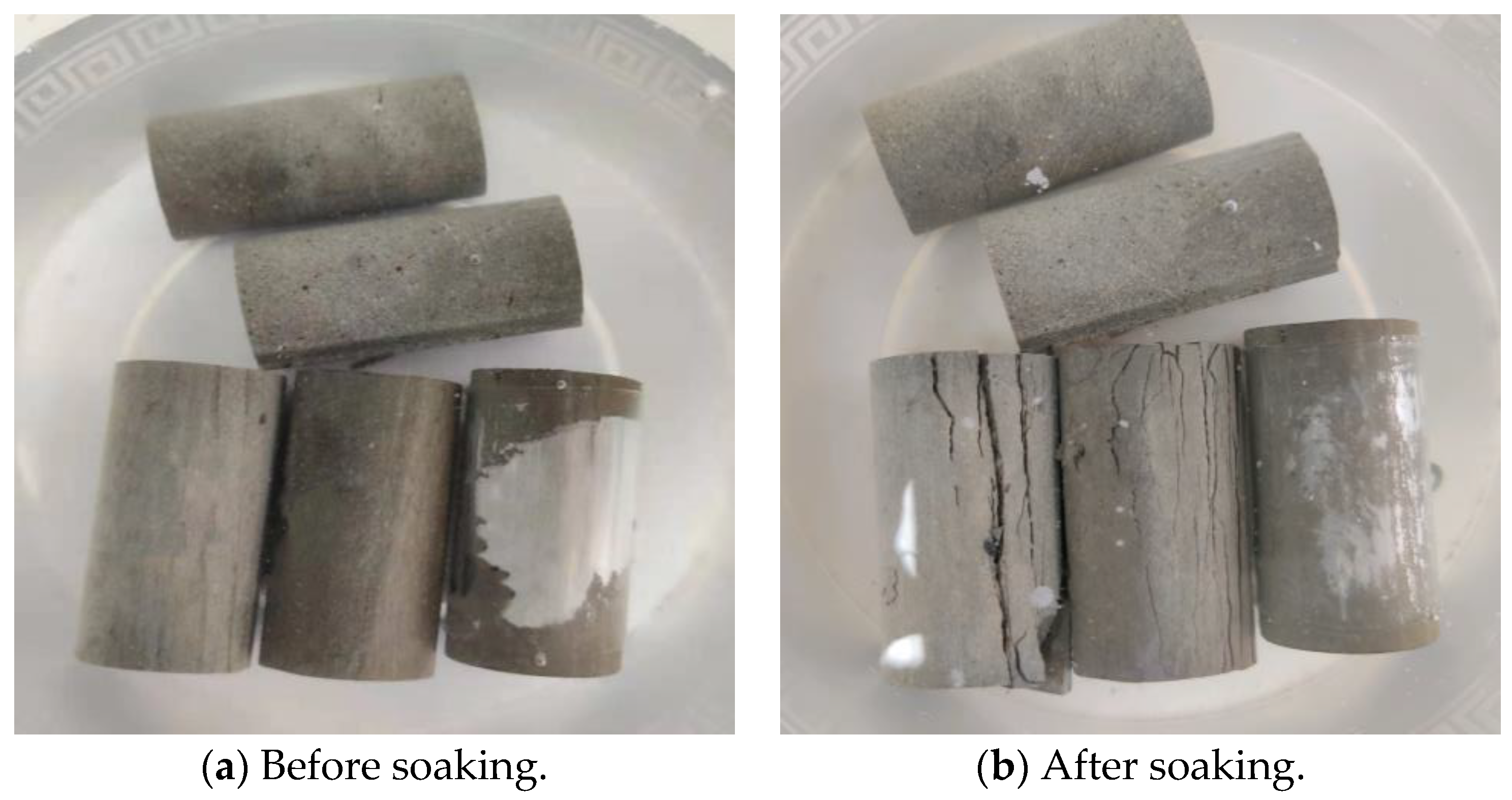
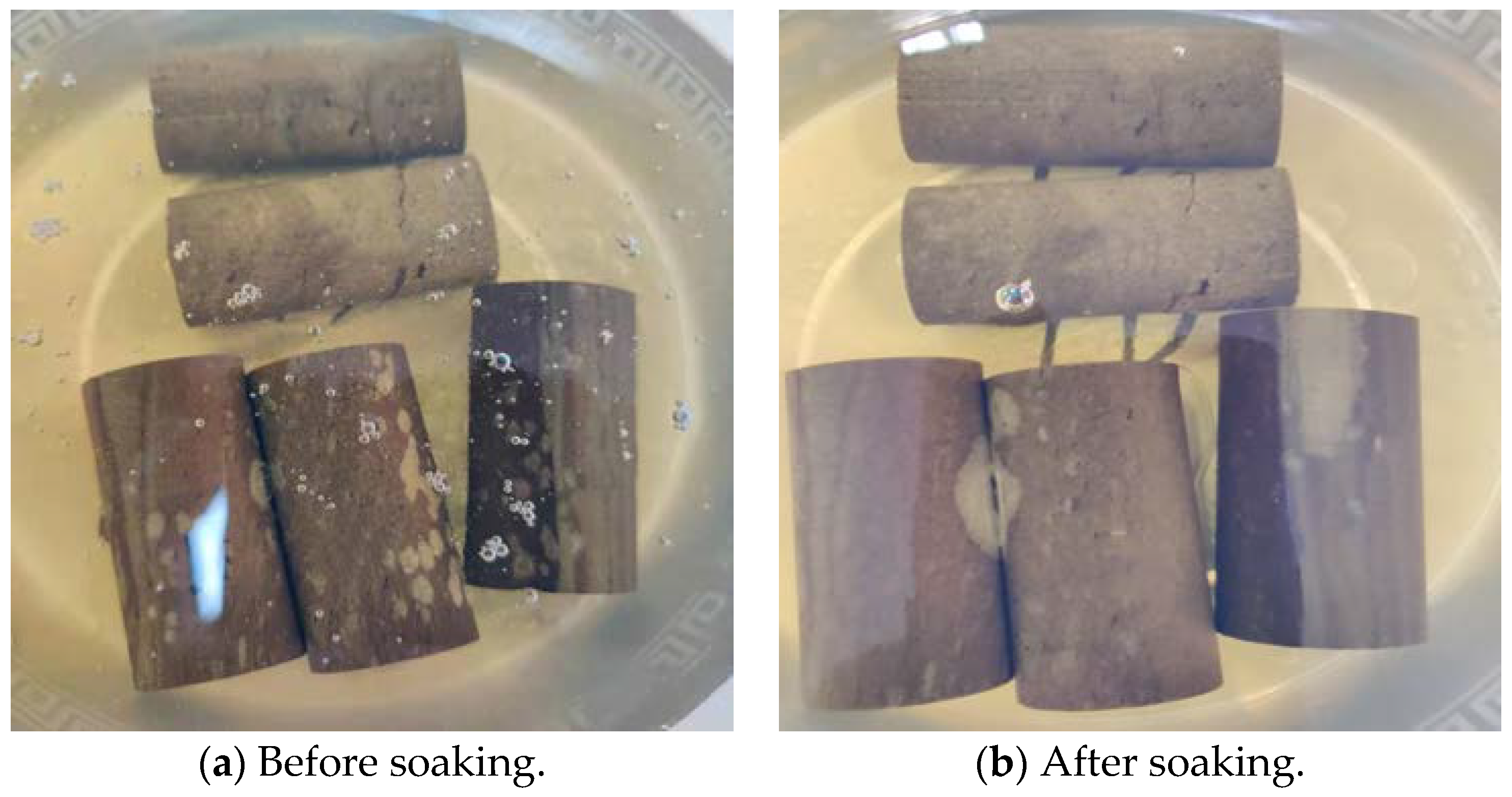
2.3. Triaxial Compressive Strength Test of Shale under Different Fluid Immersions

The vertical coring shale and the horizontal coring shale were immersed in pure water and diesel oil, respectively. After different times, the triaxial compressive strength test was conducted again, and the cohesion and internal friction angle were calculated. Experimental photos are shown in Figure 5 and Figure 6.
When the shale was soaked in water, three cores were directly broken within 1 h, and two cores had obvious cracks. After soaking in oil for 48 h, the surface of one core peeled off, and the other cores were not significantly broken. A comparison of the amount and time of core damage in water and in oil revealed that the damage rate of water to shale cores is much higher than that of oil to shale cores [12].
After soaking for 48 h, the unbroken cores were subjected to triaxial testing. According to the experimental results in Table 3, it can be seen that the shale cored parallel to the bedding direction was completely broken after soaking in water. The triaxial strength was reduced to 0, and the strength was reduced by 100%. The average triaxial strength of the shale after being soaked in oil was 45.728 MPa, and the strength decreased by 31.9%. The average triaxial strength of the shale in the vertical bedding direction was 38.907 MPa after soaking in water, and the strength decreased by 61%. The average triaxial strength after oil soaking was 63.874 MPa, which was almost unchanged compared with the original rock sample.

2.4. Tensile Strength Test of Shale

The tensile strength of the shale was tested by the Brazilian splitting method. It can be seen from the test results in Table 4 that the tensile strength of the shale varies greatly in the vertical and horizontal directions.
According to the fracture morphology of the rock in Figure 7, tensile failure is prone to occur along the bedding plane of the rock, which is an important factor that affects the stability of the well wall [13].

3. Study on the Deterioration Law of Shale under the Action of Fluid

Shale is a rock that is composed of water-sensitive clay minerals whose interaction with drilling fluids is inevitable [14]. Due to the characteristics of shale’s structure and composition, the effect of different drilling fluid systems is also very different. Most shale is strong enough to withstand borehole stress for some time as the bit cuts through the shale formation [15]. However, over time, the strength of the shale decreases significantly, regardless of the type of drilling fluid used. This is due to hydration, which occurs even with very little water uptake by the shale. This creates a zone of softening around the well, leading to the delayed failure of the shale [16].
The main components of shale are clay minerals. The composition, content and microstructure of the clay minerals determine the basic physical and chemical properties and hydration mechanism of the shale. Understanding the hydration mechanism of shale is the basis of analyzing the stability of shale wellbore. When the shale is in contact with the drilling fluid, the transport of water and ions is induced, driven by hydraulic and chemical potential gradients. These include the Darcy flow, which is driven by the pressure difference between the drilling fluid column pressure and the pore pressure, and ion diffusion, which is driven by the chemical potential difference between the drilling fluid and the shale [17].
According to C.H. Yew [18], hydration of the shale formation around the well can be described by a diffusion equation of water molecules. The water absorption diffusion equation of shale wellbore can be established by the law of conservation of mass. Let q be the mass flow of water adsorption, and let W(r, t) be the weight percentage of adsorbed water at point r away from the well axis and time t. In the conservation of mass, the following expression is needed:
q = W t
Assumptions:
q = C f W
where is the gradient operator, and C f represents the adsorption constants of materials, which are related to the properties of the shale and the drilling fluid and can be measured with the water adsorption test.
Substitute Equation (2) into Equation (1). In the cylindrical coordinate system, the basic equation of water adsorption can be obtained as follows:
C f 1 r r ( r W r ) = W t
Under boundary conditions at infinity, the formation water content is the original formation water content. At the well wall, the formation water content is considered saturated and does not change with time:
W | r = r w = W s ,     W | r = W 0 ,   0 < t <
Initial conditions:
W | t = 0 = W 0
Using the finite difference method to solve the above equation, the water content of the formation around the borehole at different locations at different times can be obtained. Let the time step be Δ t and the radial distance step be Δ h . Therefore, the radial distance is r i = i Δ h , and the time is t i = j Δ t ( i = ( 0 , 1 , 2 , n ) ; j = ( 0 , 1 , 2 , m ) ) . W ( r i , t j ) is recorded as W ( i , j ) ( i = ( 0 , 1 , 2 , n ) ; j = ( 0 , 1 , 2 , m ) ) . Approximately, replace W t , W r with the forward difference quotient and 2 W r 2 with the second central difference quotient, namely:
W t = W ( i , j + 1 ) W ( i , j ) Δ t
W r = W ( i + 1 , j ) W ( i , j ) Δ h
2 W r 2 = W ( i + 1 , j ) 2 W ( i , j ) + W ( i 1 , j ) Δ h 2
Substituting (6)~(8) into Equation (3), the difference equation of Equation (3) is:
W ( i + 1 , j ) 2 W ( i , j ) + W ( i 1 , j ) Δ h 2 + 1 r i W ( i + 1 , j ) W ( i , j ) Δ h = 1 C f W ( i , j + 1 ) W ( i , j ) Δ t
The difference format for boundary conditions and initial conditions is:
W ( 0 , j ) = W s , W ( n , j ) = W 0 , W ( i , 0 ) = W 0
According to the above experimental results, the shale water absorption rate equation is modified, and the water content of the shale formation around the borehole at different times and positions can be obtained using a numerical simulation method.
The formation collapse pressure can be calculated by the following formula [19]:
P b = 1 2 ( 3 σ H σ h ) ( 1 sin φ 0 ) + α P p sin φ 0 C 0 cos φ 0
where P b is collapse pressure (MPa); σ H is the maximum horizontal stress (MPa); σ h is the minimum horizontal formation stress (MPa); P p is the formation pore pressure (MPa); C 0 is the cohesion (MPa); φ 0 is the angle of internal friction (°); and α is the effective stress coefficient.
In order to facilitate the design of the drilling fluid density window, the collapse pressure is converted into the form of equivalent density, that is, the drilling fluid density required to just balance the formation collapse pressure, g/cm3.
According to the test results of the rock mechanical parameters soaked in different fluids, the shale deteriorates after drilling fluid soaking due to the existence of cleavage and microfractures [20]. As the conductivity of the structural plane is much higher than that of raw rock, the penetration of drilling fluid along the structural plane will directly cause the weakening of the structural plane strength [21]. As shown in Figure 8, the stress distribution of the vertical well section, the deflection section and the horizontal section of the wellbore in a bedded shale formation is established. The mechanical parameters of the surrounding rock of the wellbore are obtained from the above triaxial compressive strength test results. The change in the cohesion force and the internal friction angle after the core soaking experiment are used to characterize the weakening of the shale’s strength, and the force-chemical coupling finite element numerical simulation model of borehole collapse pressure is obtained. It can be clearly seen that stress concentration occurs at the intersection of the well wall and the bedding plane. Under the action of the liquid column pressure in the wellbore, the drilling fluid can easily enter the bedding and increase the collapse pressure around the wellbore.
In the drilling process of shale formations, the rock strength decreases, and its bearing capacity weakens, and the increased stress leads to an enhanced trend of rock collapse around the well, which is quantitatively reflected in the increase in collapse pressure, leading to wellbore instability [22]. Therefore, finite element numerical simulation is employed to calculate the collapse pressure equivalent density of the shale around the well at different water content times, which can more intuitively analyze the influence of water absorption on the deterioration degree of the shale and the borehole wall stability. Changing the action time of the drilling fluid in the wellbore and the shale bedding plane under a different well inclination and azimuth in Figure 8 until the liquid content of the surrounding rock reaches 5%, 10% and 15%, the derived values were utilized to calculate the maximum collapse pressure and the equivalent density of the collapse pressure of different schemes.
Figure 9 shows the distribution chart of the equivalent density of collapse pressure when the liquid content around the well reaches 5%, 10% and 15% under different well inclination and azimuth conditions. When the shale liquid content around the well is 5%, the variation range of the equivalent density of the collapse pressure under different wellbore trajectories is 1.02~1.53 g/cm3. When the liquid content of the shale reservoir increases, the shale strength changes, and the equivalent density of the borehole collapse pressure decreases rapidly. The collapse density increases from 0.15 to 0.22 g/cm3 and from 0.31 to 0.45 g/cm3 when the liquid content is 10% and 15%, respectively. At a certain time, the water absorption of the shale decreases with the increasing distance from the borehole wall. A hydration zone is formed in the shale formation around the borehole; however, its liquid content is similar to the original liquid content after a certain distance. At a certain distance, the longer the time, the more water absorption of the shale occurs, but at a certain time, saturation and stability will occur.
After the ground layer is drilled, driven by the pressure difference and chemical potential difference between the drilling fluid and the formation pore fluid, the drilling fluid filtrate enters the formation, causing a change in the mechanical properties of the shale [23]. The loss of filtrate from the drilling fluid increases the water content of the formation around the borehole, which leads to a series of changes in the mechanical properties of the formation. For example, the elastic modulus sharply decreases with increasing formation water content, and Poisson’s ratio increases with increasing formation water content, whereas the cohesion and internal friction angle of the formation strength decrease with increasing formation water content [24]. These changes are particularly pronounced in near-wellbore formations. The fluid loss caused a softening zone around the borehole wall, which greatly affected the stability of the borehole wall. Under a certain pressure and temperature, the interaction between the shale and the drilling fluid produces a hydration zone around the borehole [25]. The size of the hydration zone depends on the formation and drilling fluid characteristics, drilling fluid column pressure, interaction time between the drilling fluid and formation, interaction time between formation and the drilling fluid temperature, etc. Because of the formation hydration zone around the borehole, the rock around the borehole becomes a complex rock mass medium with a variable water content, modulus and strength that vary with radius and time. As a result, the strength of the shale in certain areas around the well is reduced, and a plastic zone appears or further expands to cause wellhole collapse.

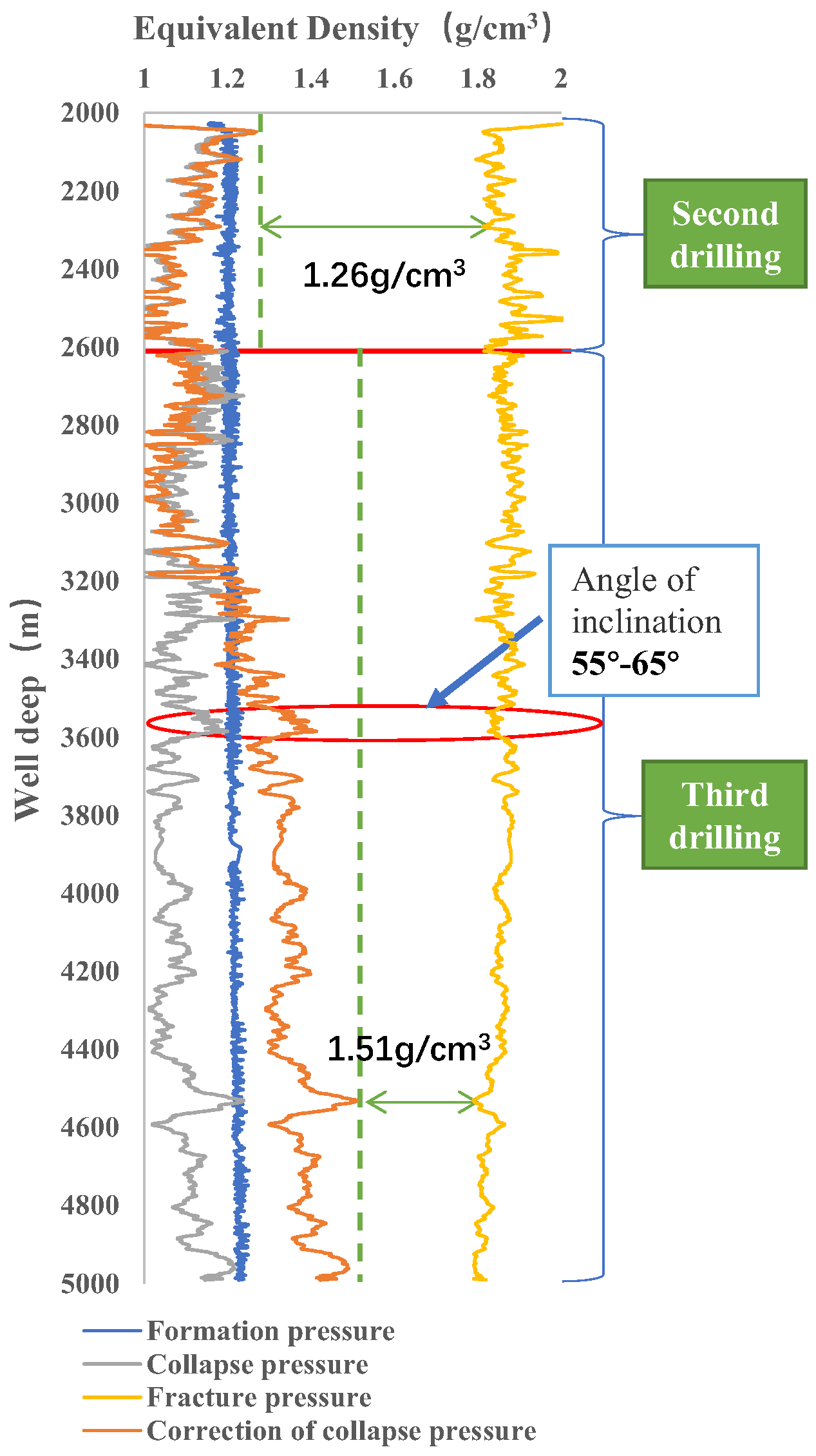
4. Field Case Analysis

A horizontal well in the Nanpu block of the Jidong Oilfield was unstable during drilling, which caused serious downhole accidents, such as well collapse and stuck drilling. The shale in this area has obvious bedding, so if the conventional model is selected to analyze the borehole wall collapse problem, the result is very different from the actual situation. Therefore, the calculation model of the equivalent density of collapse pressure with different water contents is used to correct the results, and a reasonable safe density window of drilling fluid is obtained.
The well depth of the well to be designed is 4996 m, and the length of the horizontal section is 1200 m. Adjacent wells were drilled with a maximum drilling fluid density of 1.45 g/cm3. Due to the low density of the drilling fluid, five wellbore collapse and sticking accidents occurred. It took 32 days to deal with complex downhole accidents, and 700.77 m³ of drilling fluid was lost. An analysis of the reasons for the incidents showed that shale microfissures in the Dongying Formation and the Shahejie Formation developed. Most shale formations are strong enough to withstand borehole stress for a certain period as the bit cuts through them. Over time, however, due to the hydration of the shale, even though the water uptake may be small, regardless of the type of drilling mud used, the strength of the shale will significantly decrease, creating a softening zone around the well and causing delayed rock failure. The collapse pressure is corrected according to the well trajectory and drilling construction period, and the safe drilling fluid density window is obtained as shown in Figure 10.
The well was drilled to the Shahejie Formation with water-based drilling fluid in the second drilling. The depth of the well is 2615 m. The estimated construction period is 12 days. The liquid density is 1.26 g/cm3. In the third drilling, oil-based drilling fluid was used to drill to a well depth of 4996 m, and the construction period was 34 days. After calculating the rock deterioration, the maximum collapse pressure appeared in the well inclination angle of 55°~65° and the horizontal reservoir. The maximum collapse pressure of this well section is 1.51 g/cm3, the minimum rupture pressure is 1.79 g/cm3, and the density window is narrow. The recommended drilling fluid density is 1.51 g/cm3. Drilling under the density of the drilling fluid, the well wall did not collapse, and the drilling was successfully completed.
It can be seen that the weakening strength of the shale bedding surface (increased water content) has a significant effect on the wellbore stability of horizontal wells. For any bedding surface occurrence, the collapse pressure increases with increasing water content, and the collapse pressure caused by the weakening of the bedding surface increases by approximately 0.32 g/cm3 compared with that without weakening. The weakening of shale planes is the main controlling factor of shaft wall collapse, and its influence cannot be disregarded. The drilling fluid intrudes into the stratum along the bedding under the action of osmosis, which reduces the cohesion and the internal friction angle of the bedding plane and increases the risk of shear slip of the borehole wall rock along the bedding, thus aggravating the risk of borehole wall collapse and instability. For drilling sites, if the influence of the shale strength deterioration in the drilling fluid on collapse pressure is not taken into account, the drilling fluid density may then be low, causing the collapse of the borehole wall at an early stage of drilling.

5. Conclusions

(1)
The shale in the Nanpu Depression is mainly argillaceous with dense and hard structures. Scanning electron microscopy showed that the pores were not developed, and the micropores were sporadically distributed, but the microcracks and micropores were relatively developed.
(2)
Considering the collapse and rupture of the wellbore, the collapse belongs to bulk shear when the well inclination is 0°~30°, and the rupture pressure and collapse pressure are both low. When the well inclination is 30°~60°, the drilling fluid density window is the narrowest. Precise pressure control should be ensured. When the inclination angle is 60°~90°, the collapse belongs to bedding splitting, and both the collapse pressure and the rupture pressure increase.
(3)
Through the oil–water immersion strength deterioration experiment, the effect of shale oil-based drilling fluid in the Nanpu block is better than that of water-based drilling fluid.
(4)
An analysis revealed that after the drilling fluid contacts the shale formation, the formation near the borehole wall quickly absorbs water, and its water content quickly reaches the saturation value, which substantially changes the mechanical parameters of the rock, which is manifested as a sharp decrease in rock strength. The formation near the borehole wall becomes a softening zone, which hinders borehole wall instability.

Author Contributions

Conceptualization, X.X. and K.Z.; methodology, C.C.; software, C.W.; validation, Y.Z., J.P. and W.S.; formal analysis, C.W.; investigation, X.X. and C.C.; resources, C.C.; data curation, S.L.; writing—original draft preparation, C.W.; writing—review and editing, C.W.; visualization, C.W.; supervision, X.X.; project administration, S.L.; funding acquisition, S.L. All authors have read and agreed to the published version of the manuscript.

Funding

This research was funded by [Natural Science Foundation of China], grant number [51874098].

Data Availability Statement

Not applicable.

Conflicts of Interest

The authors declare no conflict of interest.

References

  1. Zhao, W.; Liu, Y.; Wang, T.; Ranjith, P.G.; Zhang, Y. Stability Analysis of Wellbore for Multiple Weakness Planes in Shale Formations. Geomech. Geophys. Geo-Energy Geo-Resour. 2021, 7, 44. [Google Scholar] [CrossRef]
  2. Liu, X.; Zeng, W.; Liang, L.; Lei, M. Wellbore Stability Analysis for Horizontal Wells in Shale Formations. J. Nat. Gas Sci. Eng. 2016, 31, 1–8. [Google Scholar] [CrossRef]
  3. Li, Y.; Fu, Y.; Tang, G.; She, C.; Guo, J.; Zhang, J. Effect of Weak Bedding Planes on Wellbore Stability for Shale Gas Wells. In Proceedings of the IADC/SPE Asia Pacific Drilling Technology Conference and Exhibition, Tianjin, China, 9–11 July 2012. [Google Scholar]
  4. Heng, S.; Guo, Y.; Yang, C.; Daemen, J.J.K.; Li, Z. Experimental and Theoretical Study of the Anisotropic Properties of Shale. Int. J. Rock Mech. Min. Sci. 2015, 74, 58–68. [Google Scholar] [CrossRef]
  5. Al-Bazali, T. The Impact of Water Content and Ionic Diffusion on the Uniaxial Compressive Strength of Shale. Egypt. J. Pet. 2013, 22, 249–260. [Google Scholar] [CrossRef] [Green Version]
  6. Zhang, Q.; Fan, X.; Chen, P.; Ma, T.; Zeng, F. Geomechanical Behaviors of Shale after Water Absorption Considering the Combined Effect of Anisotropy and Hydration. Eng. Geol. 2020, 269, 105547. [Google Scholar] [CrossRef]
  7. Wang, Y.; Liu, X.; Liang, L.; Xiong, J. Experimental Study on the Damage of Organic-Rich Shale during Water-Shale Interaction. J. Nat. Gas Sci. Eng. 2020, 74, 103103. [Google Scholar] [CrossRef]
  8. Abdideh, M.; Mafakher, A. Wellbore Stability Analysis in Oil and Gas Drilling by Mechanical, Chemical and Thermal Coupling (Case Study in the South of Iran). Geotech. Geol. Eng. 2021, 39, 3115–3131. [Google Scholar] [CrossRef]
  9. Zou, D.; Han, Z.; Huang, H. Sensitivity Analysis of Time Dependent Wellbore Instability and Application. In Proceedings of the International Field Exploration and Development Conference 2019, Chengdu, China, 16–18 September 2019; Springer: Singapore, 2020; pp. 534–550. [Google Scholar]
  10. Changhao, W.; Ling, Z.; Shibin, L.; Huizhi, Z.; Kai, L.; Xiaoming, W.; Chunhua, W. Time-Sensitive Characteristics of Bedding Shale Deterioration under the Action of Drilling Fluid. Lithosphere 2022, 2022, 3019090. [Google Scholar] [CrossRef]
  11. Ding, L.; Lv, J.; Wang, Z.; Liu, B. Borehole Stability Analysis: Considering the Upper Limit of Shear Failure Criteria to Determine the Safe Borehole Pressure Window. J. Pet. Sci. Eng. 2022, 212, 110219. [Google Scholar] [CrossRef]
  12. Peng, S.; Shevchenko, P.; Periwal, P.; Reed, R.M. Water-Oil Displacement in Shale: New Insights from a Comparative Study Integrating Imbibition Tests and Multiscale Imaging. SPE J. 2021, 26, 3285–3299. [Google Scholar] [CrossRef]
  13. Zhang, S.W.; Shou, K.J.; Xian, X.F.; Zhou, J.P.; Liu, G.J. Fractal Characteristics and Acoustic Emission of Anisotropic Shale in Brazilian Tests. Tunn. Undergr. Space Technol. 2018, 71, 298–308. [Google Scholar] [CrossRef]
  14. Saleh, T.A. Advanced Trends of Shale Inhibitors for Enhanced Properties of Water-Based Drilling Fluid. Upstream Oil Gas Technol. 2022, 8, 100069. [Google Scholar] [CrossRef]
  15. Jiang, Z.; Yu, S.; Deng, H.; Deng, J.; Zhou, K. Investigation on Microstructure and Damage of Sandstone Under Cyclic Dynamic Impact. IEEE Access 2019, 7, 145–158. [Google Scholar] [CrossRef]
  16. He, S.; Liang, L.; Zeng, Y.; Ding, Y.; Lin, Y.; Liu, X. The Influence of Water-Based Drilling Fluid on Mechanical Property of Shale and the Wellbore Stability. Petroleum 2016, 2, 61–66. [Google Scholar] [CrossRef] [Green Version]
  17. Zhang, Q.; Yao, B.; Fan, X.; Li, Y.; Li, M.; Zeng, F.; Zhao, P. A Modified Hoek-Brown Failure Criterion for Unsaturated Intact Shale Considering the Effects of Anisotropy and Hydration. Eng. Fract. Mech. 2021, 241, 107369. [Google Scholar] [CrossRef]
  18. Yew, C.H.; Chenevert, M.E.; Wang, C.L.; Osisanya, S.O. Wellbore Stress Distribution Produced by Moisture Adsorption. SPE Drill. Eng. 1990, 5, 311–316. [Google Scholar] [CrossRef]
  19. Moos, D.; Peska, P.; Finkbeiner, T.; Zoback, M. Comprehensive Wellbore Stability Analysis Utilizing Quantitative Risk Assessment. J. Pet. Sci. Eng. 2003, 38, 97–109. [Google Scholar] [CrossRef]
  20. Huang, T.; Cao, L.; Cai, J.; Xu, P. Experimental Investigation on Rock Structure and Chemical Properties of Hard Brittle Shale under Different Drilling Fluids. J. Pet. Sci. Eng. 2019, 181, 106185. [Google Scholar] [CrossRef]
  21. Dokhani, V.; Yu, M.; Bloys, B. A Wellbore Stability Model for Shale Formations: Accounting for Strength Anisotropy and Fluid Induced Instability. J. Nat. Gas Sci. Eng. 2016, 32, 174–184. [Google Scholar] [CrossRef]
  22. Ma, T.; Chen, P. Influence of Shale Bedding Plane on Wellbore Stability for Horizontal Wells. J. Southwest Pet. Univ. (Sci. Technol. Ed.) 2014, 36, 97–104. [Google Scholar] [CrossRef]
  23. Yan, C.; Deng, J.; Yu, B. Wellbore Stability in Oil and Gas Drilling with Chemical-Mechanical Coupling. Sci. World J. 2013, 2013, e720271. [Google Scholar] [CrossRef] [PubMed] [Green Version]
  24. Zhang, F.; Xie, S.Y.; Hu, D.W.; Shao, J.F.; Gatmiri, B. Effect of Water Content and Structural Anisotropy on Mechanical Property of Claystone. Appl. Clay Sci. 2012, 69, 79–86. [Google Scholar] [CrossRef]
  25. Liu, J.; Yang, Z.; Sun, J.; Dai, Z.; You, Q. Experimental Investigation on Hydration Mechanism of Sichuan Shale (China). J. Pet. Sci. Eng. 2021, 201, 108421. [Google Scholar] [CrossRef]
Figure 1. Mineral composition of shale in the Nanpu block.
Energies 16 02989 g001
Figure 2. SEM image of deep shale in Nanpu block.
Energies 16 02989 g002
Figure 3. The failure form of shale under different loading directions.
Energies 16 02989 g003
Figure 4. Core anisotropic failure law.
Energies 16 02989 g004
Figure 5. Soaking in water for 48 h.
Energies 16 02989 g005
Figure 6. Soaking in diesel oil for 48 h.
Energies 16 02989 g006
Figure 7. Fragmentation morphology of loaded shale in different bedding directions.
Energies 16 02989 g007
Figure 8. The von Mises stress around the borehole wall for different well types and water contents.
Energies 16 02989 g008
Figure 9. Collapse pressure distribution under different well types and water contents.
Energies 16 02989 g009
Figure 10. Corrected safe drilling fluid density window.
Energies 16 02989 g010
Table 1. Triaxial stress test results.
Loading DirectionLithologyConfining Pressure (MPa)Compressive Strength (MPa)Young’s Modulus (MPa)Poisson’s Ratio
Vertical bedding directionLight gray fine shale6099.81714,924.70.16
Parallel bedding directionDark gray mud shale6067.1469979.20.20
Table 2. Experimental results of rock mechanics parameters in different loading directions.
Load DirectionCohesion (MPa)Angle of Internal Friction (°)Coefficient of Internal Friction
Parallel bedding direction11.38612.950.23
Vertical bedding di-rection22.46413.060.232
30° bedding direction15.6987.570.133
45° bedding direction8.3386.390.112
60° bedding direction4.7754.40.077
Table 3. 48 h triaxial stress test results of shale soaking.
Types of ExperimentsConfining Pressure (MPa)Compressive Strength (MPa)Young’s Modulus (MPa)Poisson’s Ratio
Soaking in water (parallel)broken000
000
000
Soaking in oil (parallel)6049.6779537.90.21
broken000
6041.77813,057.20.2
Soaking in water (vertical)6038.94415,396.50.21
6038.8698608.50.23
Soaking in oil (vertical)6064.22513,322.70.19
6063.52310,173.90.22
Table 4. Shale tensile strength test results in vertical/parallel bedding directions.
Coring DirectionStratumTensile Strength (MPa)Average Tensile Strength (MPa)
VerticalEs17.998.07
8.15
ParallelEs13.393.22
3.05
Disclaimer/Publisher’s Note: The statements, opinions and data contained in all publications are solely those of the individual author(s) and contributor(s) and not of MDPI and/or the editor(s). MDPI and/or the editor(s) disclaim responsibility for any injury to people or property resulting from any ideas, methods, instructions or products referred to in the content.

