Article

New Approach to Evaluate the Transformation Accuracy of Inductive CTs for Distorted Current

Institute of Mechatronics and Information Systems, Lodz University of Technology, 90-537 Lodz, Poland
*
Author to whom correspondence should be addressed.
Energies 2023, 16(7), 3026; https://doi.org/10.3390/en16073026
Submission received: 30 January 2023 / Revised: 9 March 2023 / Accepted: 24 March 2023 / Published: 26 March 2023

Abstract

:
This paper presents a newly developed method to determine the values of current error and phase displacement for the transformation of distorted current harmonics by the inductive current transformers. This approach eliminates the necessity for the utilization of an expensive, high-current supply system for the measuring setup. In this method, the secondary winding is fed by the distorted voltage with RMS values of harmonics calculated in order to reproduce the operation point of the inductive current transformer on the magnetization characteristic of its magnetic core, as in primary winding excitation conditions. This proposed approach is successfully verified with the typically used primary current excitation method, where the secondary currents of the reference and tested current transformers are compared in the differential measuring setup. It was confirmed that the inductive CT with current error and phase displacement for transformation of distorted current harmonics determined in the rated ampere-turns conditions may be effectively used in the measuring setup as the reference source of the primary current.

1. Introduction

Inductive current transformers (CTs) are devices that are used to transform high currents into an appropriate level for measuring and as a protection apparatus of the electrical power system [1,2]. CTs are widely used in the monitoring of power generation, transmission and distribution. The transformation accuracy of the CTs is critical to the reliability of the power network and energy billing. Inductive CTs are designed to ensure transformation accuracy over a specific range of the primary current. Its upper value is limited by the knee point on the magnetization characteristic of the magnetic core. This is where its nonlinear part begins. Further increase in the value of magnetic flux density will cause saturation of the magnetic core [3,4,5,6,7]. The secondary current of the inductive CT will be strongly distorted by the self-generation of higher harmonics caused by the nonlinearity of the magnetization characteristic of the magnetic core. This phenomenon is typical for CTs with the magnetic core. The magnetization characteristic, even below the knee point, is nonlinear, and some level of the low order higher harmonics is generated to the secondary current. The pure sinusoidal waveforms of the current never exists in the electrical power system. Its frequency spectrum consists of not only fundamental components but also higher harmonics. This is due to an increased number of loads connected to the power grid with the nonlinear current to the voltage relationship [8,9]. Moreover, the renewable energy sources may introduce additional distortion. Therefore, all devices belonging to the electrical energy system are exposed to the current components other than rated frequencies. The new edition of the standard IEC 61869-1 will be introduced in 2023 and contains the optional requirements for transformation accuracy of higher harmonics by the inductive CTs. Many of the papers [10,11,12,13,14,15,16] present behavior and accuracy tests of inductive CTs during transformation of the distorted current. However, most of them are based on the utilization of the high-current test system, which have to be able to generate distorted currents associated with the rated primary current of the tested CT. Other problems concern the devices which may be adopted as a reference source of the primary current. A solution for this problem is presented in the papers [17,18,19]. In this case, the low primary current transformer (LPCT) was used. Another device, which can be adopted for this purpose, is the inductive CT characterized by a high accuracy of transformation for distorted current higher harmonics. Its accuracy is then tested in its rated ampere-turns conditions [20,21,22]. The inductive CT must be a bushing or window type. The additional primary winding with the number of turns equal to the rated current ratio has to be made. It is required to be evenly spread on the surface of the magnetic core.
The paper presents a new approach to evaluate the transformation accuracy of inductive CTs for transforming distorted current harmonics. In this method, the secondary winding is fed by the distorted voltage with the RMS values of harmonics calculated in order to reproduce the operation point of the inductive CT on the magnetization characteristic of its magnetic core under primary winding excitation conditions. Therefore, the values of resistance and reactance of the secondary winding and its load must be considered. It has been proven that the value of reactance of the secondary winding may be estimated from the measured value of its DC resistance by multiplying it by the factor equal to 0.1. To determine the value of the current error and phase displacement for a given hk harmonic of the distorted secondary voltage representing the considered distorted primary current, the RMS values of the hk harmonics of the secondary winding excitation current and phase shift between them are measured.
The novelty of this paper is summarized in the following bullet points:
  • The method to determine current error and phase displacement for the transformation of distorted current harmonics by the inductive CTs without the high current generation system is proposed;
  • It is confirmed that the effect of the nonlinearity of the magnetic core is covered by the secondary current excitation method;
  • The proposed approach is successfully verified with the typically used primary current excitation method, where the secondary currents of the reference and tested current transformers are compared in the differential measuring setup;
  • Inductive CTs with current error and phase displacement for transformation of distorted current harmonics determined in the rated ampere-turns conditions may be effectively used in the measuring setup as the reference source of the primary current.
The differences between the results obtained by the means of the secondary and primary current excitation methods are the most significant for the main and 3rd harmonics of the considered distorted primary current. The highest difference does not exceed ±0.1% for the current error at the harmonic and ±0.1° for phase displacement at the harmonic. These values are the most important for the main component, taking into consideration the limit values of current error and phase displacement defined for a given accuracy class in the standard IEC 61869-2 and IEEE C57.13 for transformation of the sinusoidal current of frequency 50 Hz/60 Hz. Therefore, the equivalent method is found not yet suitable for accuracy tests in accordance with appropriated standards for the transformation of sinusoidal currents. The accuracy requirements for higher harmonic transformation by the inductive current transformer are still not defined by the standards. Nevertheless, the requirements for transformation of distorted current higher harmonics are expected to be several times less restrictive, and the measurement uncertainty of the proposed method would be acceptable.
Presented in this manuscript is an approach and method that can be used for the protection and measuring the types of inductive CTs. It is crucial to determine the correct values of inductance and resistance of the CT’s secondary winding. Moreover, this method can be utilized to determine the values of the current error and phase displacement of the distorted current harmonics transformation by the inductive CT characterized by even distribution of the winding turns on the surface of the magnetic core. In the other case, the measurement uncertainty of the method increases. In our laboratory studies, we tested only inductive CTs with even distribution of the primary and secondary winding turns. This is important, because the even distribution of the magnetic field strength in the magnetic core is required in order to reproduce the same conditions from the secondary side as it would be obtained during the primary excitation. To summarize, the advantages of the proposed method are listed below:
  • It eliminated the necessity of the utilization of expensive, high-current supply systems of the measuring setup;
  • It did not require the utilization of the reference source of the primary current (e.g., reference transducer/transformer);
  • It enabled the determination of the values of current error and phase displacement even for very high frequencies;
However, the disadvantages are pointed out below:
  • It required the determination of the correct values of inductance and resistance of the CT’s secondary winding,
  • It was applicable only to the inductive CTs with even distribution of the winding turns on the surface of the magnetic core.

2. Measuring Circuits

To discuss in detail the idea of the developed, secondary current excitation method used to determine the transformation accuracy of distorted current harmonics by the inductive CTs, their equivalent circuit, presented in Figure 1, is analyzed.
where:
  • i″0hk is the instantaneous value of the secondary excitation current;
  • i″μhk is the instantaneous value of the reactive component of the secondary excitation current;
  • i″Fehk is the instantaneous value of the active component of the secondary excitation current;
  • L″μhk is the nonlinear mutual inductance between windings of the inductive CT;
  • R″Fehk is the nonlinear resistance representing the active power losses in the magnetic core;
  • L2 is the leakage inductance of the secondary winding;
  • R2 is the resistance of the secondary winding;
  • u″μhk is the instantaneous value of the voltage on the mutual inductance between windings;
  • and u20hk is the instantaneous value of the equivalent secondary winding supply voltage.
In order to determine the values of the current error and phase displacement using the secondary current excitation method, the first stage involves calculating the RMS values of the distorted voltage harmonics required to supply the secondary winding of the TCT (tested current transformer). These values must be determined for the given RMS values of the distorted primary current harmonics converted to the secondary side, taking into account the resistance and reactance of the secondary winding and its load. These assumptions are necessary to adequately represent the TCT’s operation for the transformation of the distorted primary current with a specific secondary winding load. In accordance with the results and method presented in paper [23], the reactance of the secondary winding may be estimated from the measured value of its DC resistance by multiplying it by a factor equal to 0.1. To ensure the same operating point of the tested CT on the magnetization characteristic of its magnetic core, as in the conditions of primary winding excitation, it is necessary to calculate the RMS values of the harmonics of the secondary winding supply voltage. The RMS value of each harmonic is calculated in accordance with the following formula:
U 20 h k = I z 1 h k · ( R 2 + R L ) 2 + ( 2 · π · f h k · L 2 ) 2 ,
where:
  • I″z1hk is the RMS value of the hk higher harmonic of the considered distorted primary current for which the values of the current and phase displacement are determined;
  • RL is the load resistance of the secondary winding;
  • LL is the load inductance of the secondary winding;
  • and U20hk is the RMS value of the hk higher harmonic of the equivalent secondary winding supply voltage.
In the second stage of the developed method, the TCT is connected to the measuring circuit presented in Figure 2. To determine the value of the current error and phase displacement for a given hk harmonic of the considered distorted primary current, the RMS values of the excitation current I 0 h k and applied supply voltage U 20 h k as well as the phase shift between them ω h k must be measured. The value of the hk harmonic of the composite error for a given RMS value of the hk higher harmonics of the considered distorted primary current I z 1 h k can be calculated with the following formula:
ε % I A h k = I 0 h k I z 1 h k 100 % ,
where:
I″0hk is the RMS value of the measured hk harmonic of the distorted excitation current.
The RMS value of a given voltage harmonic of the mutual inductance U μ h k is equal to:
U µ h k = [ U 20 h k 2 + I 0 h k 2 · [ R 2 2 + ( 2 · π · f h k · L 2 ) 2 ] 2 · U 20 h k · I 0 h k · R 2 2 + ( 2 · π · f h k · L 2 ) 2 · c o s ( ω h k a r c t g 2 · π · f h k · L 2 R 2 ) ] 1 2 ,
The value of the hk harmonic of the current error is defined by the following equation:
Δ I A h k = ε % I A h k · c o s ( a r c c o s ( U 20 h k 2 + U h k 2 I 0 h k 2 · ( R 2 2 + ( 2 · π · f h k · L 2 ) 2 ) 2 · U 20 h k · U µ h k ) + ω h k a r c t g ( 2 · π · f h k · ( L 2 + L L ) R 2 + R L ) ) ,
The value of the hk harmonic of the phase displacement is defined by the following equation:
δ φ A h k = a r c s i n ( ε % I A h k · s i n ( a r c c o s ( U 20 h k 2 + U h k 2 I 0 h k 2 · ( R 2 2 + ( 2 · π · f h k · L 2 ) 2 ) 2 · U 20 h k · U µ h k ) + ω h k a r c t g ( 2 · π · f h k · ( L 2 + L L ) R 2 + R L ) ) · 1 100 % ) ,
The measuring circuit of the proposed secondary current excitation method is presented in Figure 2.
In Figure 2 the following abbreviations are used:
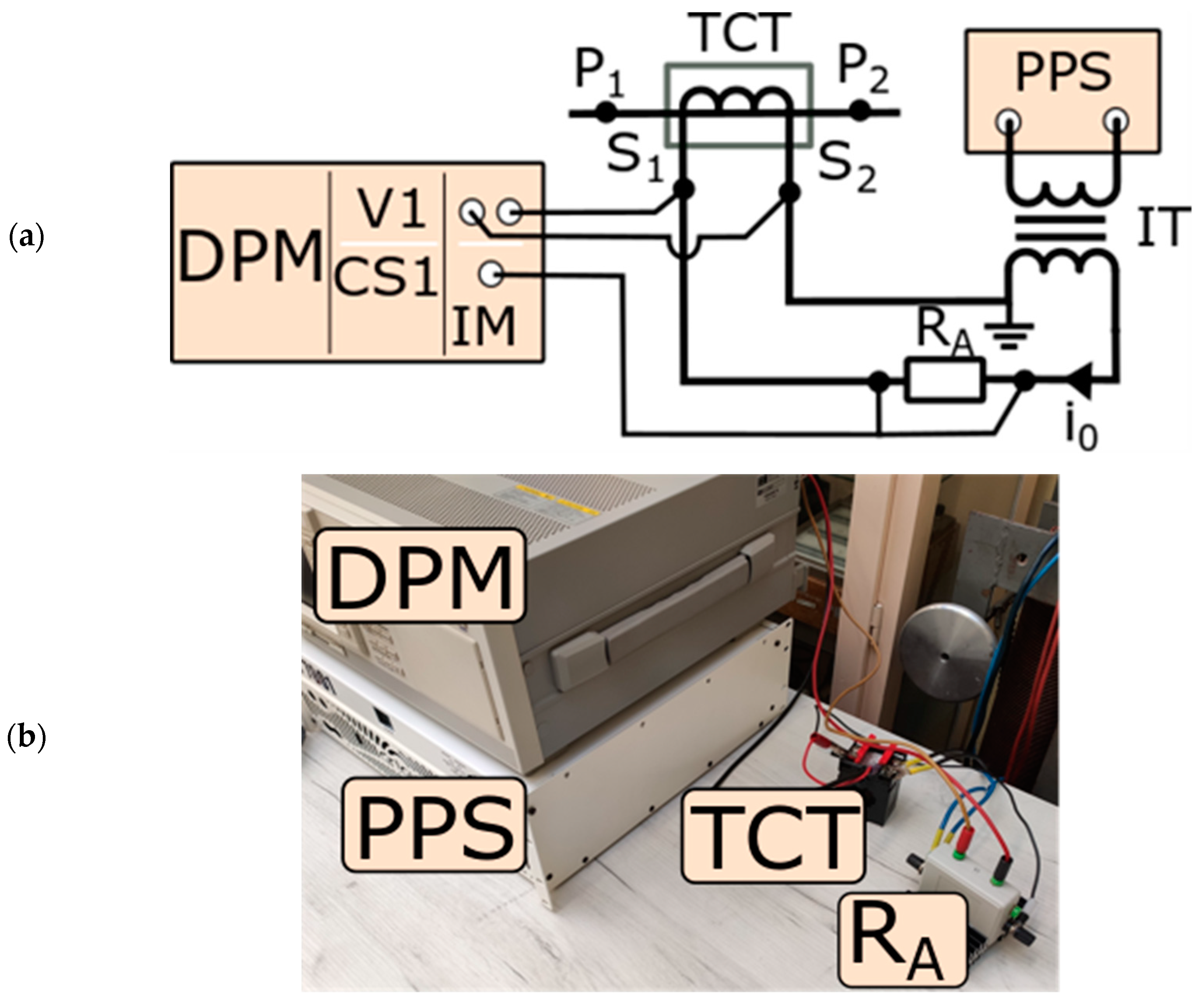
  • DPM is the digital power meter;
  • TCT is the tested inductive CT;
  • PPS is the programmable power supply;
  • IT is the insulation transformer;
  • I0 is the instantaneous value of magnetic core’s excitation current;
  • RA is the current shunt used to measure value of I0;
  • V1/CS1 is the input terminal of the DPM;
  • P1/P2 is the primary terminal of the tested CT;
  • and S1/S2 is the secondary terminal of the tested CT.
The verification of the results obtained from the proposed method was performed by comparing the determined values of the current error and phase displacement with the utilization of the primary current excitation method. The measuring setup had to be supplied with a high value of the distorted primary current resulting from the rated current ratio of the tested inductive CT. This may be accomplished using the high current generation system composed of the step-up current transformer (SCT), programmable power source (PPS) and isolation transformer (IT). The reference current transformer (RCT) is also supplied by the same primary current as the tested unit. Therefore, their secondary current may be compared.
The accuracy of the RCT is determined in the rated ampere-turns method described in detail in paper [20]. The differential circuit is used to ensure low measurement uncertainty. The value of the composite error for a given higher harmonics is directly determined from the measured value of voltage on the current shunt RD. In the measuring circuit presented in Figure 1, the current shunt RS is used to measure the RCT’s secondary current. The load of the secondary winding of the TCT is represented by the current shunt RL.
In Figure 3, the abbreviations are the same as those in Figure 1, with the addition of the following:
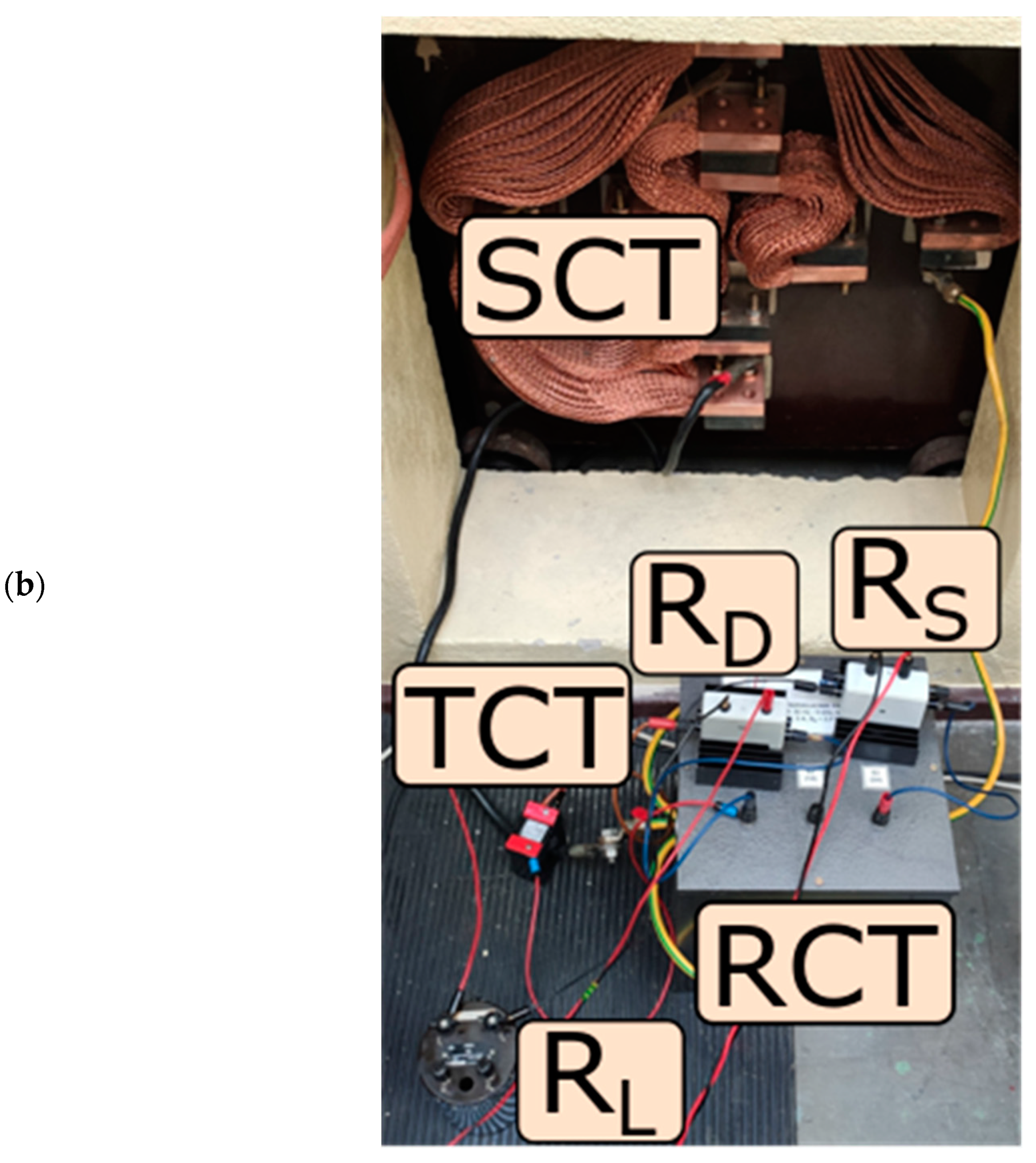
  • SCT is the step-up current transformer;
  • RD is the current shunt used to measure instantaneous value of the differential current;
  • RCT is the reference CT tested in the ampere-turns conditions;
  • RL is the load of the secondary winding of the tested CT;
  • RS is the current shunt used to measure the instantaneous value of RCTs secondary current;
  • i2 is the instantaneous value of the tested CTs secondary current;
  • i2r is the instantaneous value of the RCTs secondary current;
  • and iD is the instantaneous value of the differential current between the TCT and RCT secondary currents.
The digital power meter (DPM) enables instantaneous measurements of the RMS value of a given higher harmonics of voltages on current shunts RS and RD as well as the phase angle between them.
The percentage value of the RCT’s secondary current is determined from Equation (6) [22].
I 2 h k = U S h k R S · 100 % ,
where:
UShk is the RMS value of the hk voltage higher harmonic of the current shunt RS.
The value of the current error specified for a given hk harmonic of the distorted primary current is equal to [22]:
Δ I h k = ( U S h k R S ) 2 + ( U D h k R D ) 2 2 U S h k R S · U D h k R D c o s ϕ h k U S h k R S U S h k R S · 100 % ,
where:
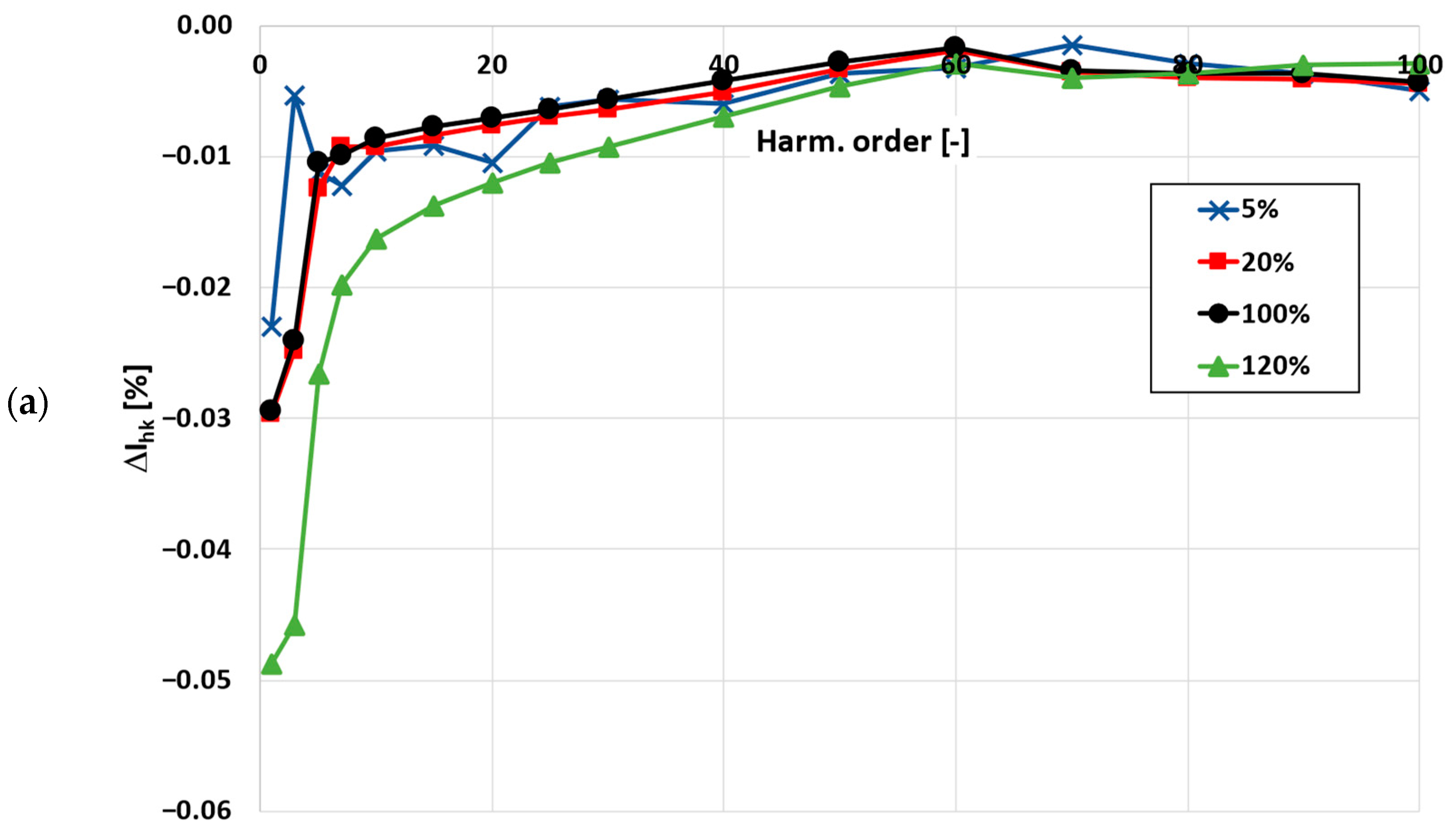
  • UDhk is the RMS value of the hk voltage higher harmonic of the current shunt RD;
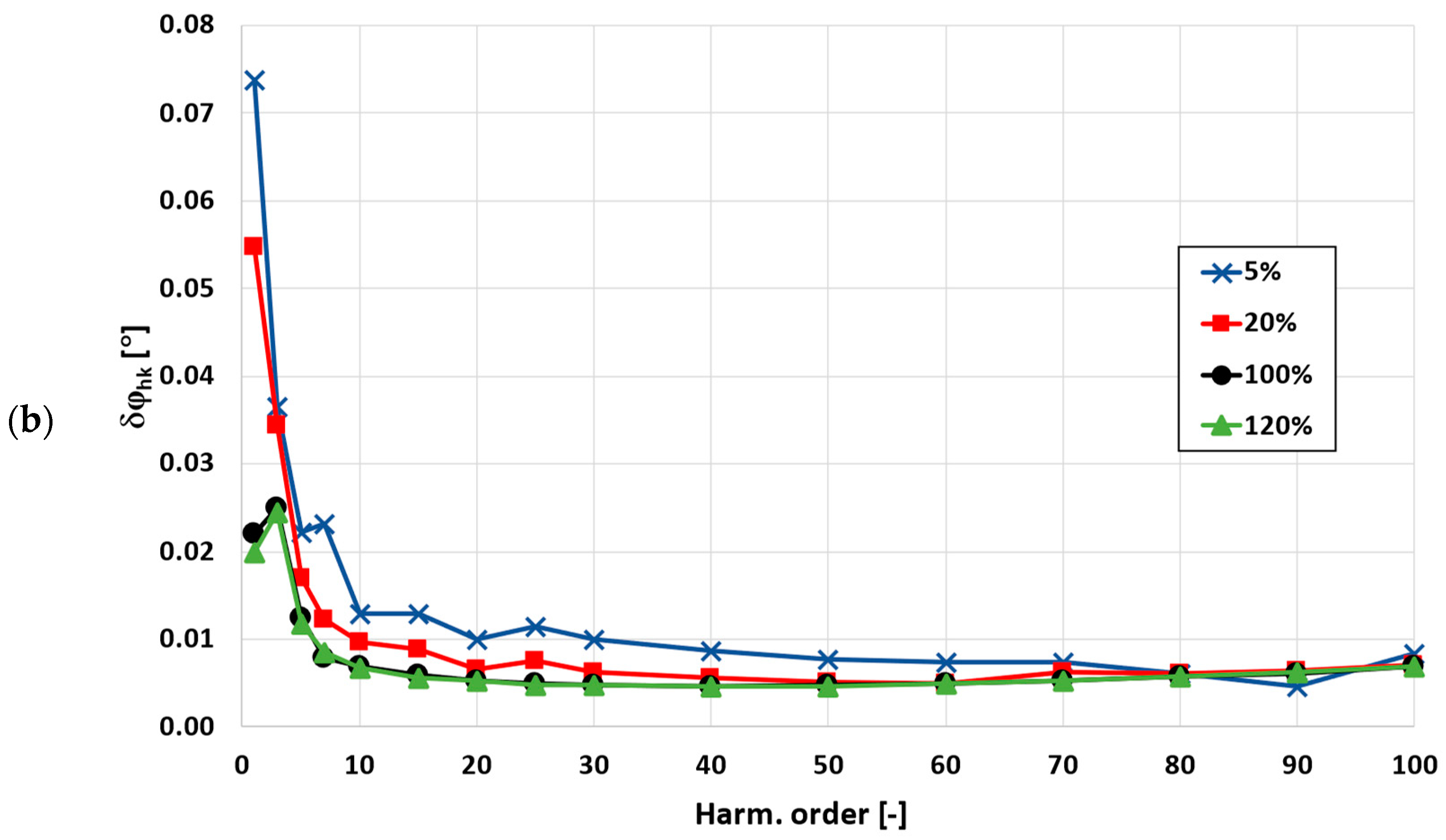
  • and ϕhk is the phase angle of the hk higher harmonic measured between voltages of the current shunts RD and RS.
The value of the phase displacement is calculated from the following equation [22]:
δ φ h k = a r c s i n ( ( U D h k · R S R D · U S h k · 100 % ) 2 Δ I h k 2 100 % ) ,
The tests were performed for the transformation of the distorted primary current with the main component of a 50 Hz frequency and a single higher harmonic frequency from 100 Hz to 5 kHz. The RMS value of the higher harmonic is equal to 10% of the main harmonic. In accordance with the standard IEC 61869-2, both inductive CTs are tested for 5%, 20%, 100% and 120% of the rated primary current RMS value. The CT with an accuracy class of 0.2S was additionally tested for 1%. Due to the different phase angle of higher harmonics in relation to the main harmonic of the distorted primary current, various values of the current error and phase displacement may be determined. Therefore, during the tests in the primary current excitation method, the phase angle of the transformed distorted primary current higher harmonic is changed by 5° in the range from 0° to 355° in relation to the main component. While, in the secondary current excitation method, the phase angle of the secondary winding supply voltage higher harmonic is also changed by 5° in the range from 0° to 355° in relation to the main component. This approach enables the possibility to evaluate the most positive and negative values of the current error and phase displacement that may be obtained for TCT due to the influence of the self-generation phenomenon [14,21,22,24]. In this paper, the highest absolute values of the current error and phase displacement are presented.

3. Reference and Tested CTs

The developed, secondary winding excitation current method was applied to two different inductive CTs. The first one had a rated current ratio of 1500 A/5 A, and its accuracy class determined for the transformation of the sinusoidal current, with a frequency of 50 Hz, was 0.2S. The second one had a rated current ratio of 100 A/5 A, and its accuracy class was 0.5. The developed, secondary current excitation method requires specifying the values of inductance and resistance of the secondary winding and parameters of the load for which the RMS values of harmonics of the secondary winding supply voltage in accordance with Equation (1) are calculated. These values for both CTs are given in Table 1.
The TCT 1500 A/1 A, cl. 0.2S is connected to the measuring circuit presented in Figure 2. To determine the value of the current error and phase displacement, the RMS values of the excitation current I 0 h k and applied supply voltage U 20 h k as well as phase shift between them and ω h k were measured. In Table 2 the results for the equivalent test conditions representing 20% of the rated primary current are reported.
The values of the voltage U 20 h k for a given hk harmonic were calculated in order to ensure equivalent conditions for the operation of the TCT magnetic core as obtained for transformation of the distorted primary current. The above presented calculations were conducted to obtain the secondary supply voltage under conditions where 20% of the rated primary current with the RMS value of the higher harmonic equal to 10% of the main harmonic is transformed by the TCT. Similar calculations were performed for 1%, 5%, 100% and 120% of the rated primary current RMS value.
The TCT 100 A/5 A, cl. 0.5 was connected to the same measuring circuit. In Table 3, the results for the equivalent test conditions representing the transformation of the distorted primary current for 100% of its rated value are reported.
In the above presented case, the calculations were performed to obtain secondary supply voltage under the conditions where the TCT transforms 100% of the rated primary current with the RMS value of the higher harmonic equal to 10% of the main harmonic. Similar calculations were performed for 5%, 20% and 120% of the rated primary current RMS value.
The results presented in Table 2 and Table 3 enable the calculation of the values of the current error and phase displacement for the transformation of a given hk harmonic of the distorted primary current by TCTs using Equations (4) and (5).
The developed, inductive RCT is designed for the rated primary current RMS value equal to 300 A. It has two secondary windings for rated secondary currents equal to 1 A and 5 A. The values of the current error and phase displacement of the RCT for transformation of the distorted current harmonics are determined by the means of the rated ampere-turns method described in detail in paper [2]. The tests were performed for the transformation of the distorted primary current with the main component of frequency being 50 Hz and a single higher harmonic frequency ranging from 100 Hz to 5 kHz. The RMS value of the higher harmonic is equal to 10% of the main harmonic. To test the CT, an additional primary winding must be made, and its number of turns results from the rated current ratio of the tested inductive CT. However, this solution is only applicable to window-type CTs. In the differential circuit, the currents in the additional primary winding and in the secondary winding of the tested CTs are compared. The frequency characteristics of the current error and phase displacement of the RCT for the rated current ratio equal to 300 A/1 A are presented in Figure 4.
The presented results in Figure 4 indicate that the values of the current error and phase displacement were the highest for the main harmonic of the transformed distorted primary current. They did not exceed −0.05% and 0.08°, respectively.
The frequency characteristics of the current error and phase displacement of the RCT for the rated current ratio equal to 300 A/5 A are presented in Figure 5.
The presented results in Figure 5 indicate that the values of the current error and phase displacement were the highest for the main harmonic of the transformed distorted primary current. They did not exceed −0.05% and 0.06°, respectively.

4. Results

The results of the values of the current error and phase displacement determined for a given harmonic of the tested CT with a rated current ration equal to 1500 A/1 A in the proposed secondary current excitation method and primary reference excitation method are presented in Figure 6. The dotted lines present the results without the consideration of the correction of the secondary winding turns. The method to determine the turns ratio correction of the tested CT is described in paper [25], where its value of considered TCT is equal to six turns. This value changes the current error by 0.4% towards positive values. The results of the tests are presented for the distorted primary current equal to 120% and 20% of the TCT’s rated current value.
The high values of the current errors and phase displacements obtained from the 3rd to 10th order harmonics result from the self-generation of low-order higher harmonics in the secondary current. The proposed method also allows for determining the influence of this phenomenon on the values of the current error and phase displacement. The convergence of the results obtained from the secondary current excitation method and the reference method confirms the effectiveness of the developed approach. However, it is necessary to also consider the turns ratio corrections. The discrepancies between the results are within the extended measurement uncertainty of both methods.
Figure 7 shows a comparison of the obtained values of the current error and phase displacement of the TCT with the rated current ratio of 100 A/5 A in the proposed secondary and primary current excitation methods. The TCT was made with the applied turns ratio correction of the secondary winding by a value of 0.1 turns. This can be achieved when the last turn is divided into 10 wires, 9 of which are made through the window of the magnetic core. The tests were conducted for the distorted primary current equal to 100% and 5% of the TCT’s rated current value.
It is important to note that the differences between the results obtained by the secondary current excitation method and the primary current excitation method are significant, especially for the main and 3rd harmonics. The highest difference reaches ±0.1% for current error and does not exceed ±0.1° for the phase displacement. These values are significant for the main component of the distorted primary current, considering the limit values of the current error and phase displacement defined for a given accuracy class in the standards IEC 61869-2 and IEEE C57.13 [26,27]. However, it should be noted that the accuracy requirements for higher harmonic transformation by the inductive current transformer are not yet defined by the standards. The limiting values of the current error and phase displacement at harmonics are proposed in paper [19]. The values defined in the standard IEC 61869-6 for the low-power instrument transformers may be also adopted [28]. Nevertheless, the requirements for the transformation of distorted current higher harmonics are several times less restrictive. The differences between the values of the current error and phase displacement determined by both methods are acceptable and do not have a significant influence on the possible designation of the wide frequency accuracy class, as the requirements for the transformation of the distorted current higher harmonics are several times less restrictive.

5. Conclusions

This paper presents a newly developed method to determine the values of the current error and phase displacement for the transformation of distorted current harmonics by the inductive current transformers. The proposed method eliminates the need for expensive, high-current supply systems in the measuring setup and provides an efficient way to determine the accuracy of inductive current transformers for the transformation of distorted current harmonics. In this method, the secondary winding is fed by the distorted voltage with RMS values of the harmonics calculated in order reproduce the operation point of the inductive current transformer on the magnetization characteristic of its magnetic core, as in the primary winding excitation conditions. The accuracy of the inductive current transformer depends on the turns ratio correction and the value of the magnetic flux density of the magnetic core resulting from the instantaneous value of the secondary voltage. All of the inductive current transformers suffer from the self-generation problem caused by the nonlinearity of the magnetization characteristic of the magnetic core. This is the main factor that determines their wide frequency transformation accuracy. The efficiency of the secondary current excitation approach was verified with the typically used primary current excitation method, where the secondary currents of the reference and tested current transformers are compared in the differential measuring setup. The convergence of the results from both methods have also confirmed the applicability of the inductive current transformer as the source of the distorted reference current. The values of the current error and phase displacement for transformation of the distorted current harmonics by the reference inductive current transformer were determined in the rated ampere-turns conditions.

Author Contributions

Conceptualization, M.K. and E.S.; methodology, M.K. and E.S.; validation, M.K. and E.S. formal analysis, M.K. and E.S.; investigation, M.K. and E.S.; resources, M.K. and E.S.; data curation, M.K. and E.S.; writing—original draft preparation, M.K. and E.S.; writing—review and editing, M.K. and E.S.; visualization, E.S.; supervision, M.K. All authors have read and agreed to the published version of the manuscript.

Funding

This research received no external funding.

Institutional Review Board Statement

Not applicable.

Informed Consent Statement

Not applicable.

Data Availability Statement

Not applicable.

Conflicts of Interest

The authors declare no conflict of interest.

References

  1. Vieira, D.; Shayani, R.A.; De Oliveira, M.A.G. Reactive Power Billing under Nonsinusoidal Conditions for Low-Voltage Systems. IEEE Trans. Instrum. Meas. 2017, 66, 2004–2011. [Google Scholar] [CrossRef]
  2. Dirik, H.; Duran, I.U.; Gezegin, C. A Computation and Metering Method for Harmonic Emissions of Individual Consumers. IEEE Trans. Instrum. Meas. 2019, 68, 412–420. [Google Scholar] [CrossRef]
  3. Hajipour, E.; Vakilian, M.; Sanaye-Pasand, M. Current-Transformer Saturation Compensation for Transformer Differential Relays. IEEE Trans. Power Deliv. 2015, 30, 2293–2302. [Google Scholar] [CrossRef]
  4. Hong, Y.Y.; Wei, D.W. Compensation of distorted secondary current caused by saturation and remanence in a current transformer. IEEE Trans. Power Deliv. 2010, 25, 47–54. [Google Scholar] [CrossRef]
  5. Bauer, J.; Ripka, P.; Draxler, K.; Styblikova, R. Demagnetization of current transformers using PWM burden. IEEE Trans. Magn. 2015, 51, 1–4. [Google Scholar] [CrossRef] [Green Version]
  6. Esmail, E.M.; Elkalashy, N.I.; Kawady, T.A.; Taalab, A.M.I.; Lehtonen, M. Detection of Partial Saturation and Waveform Compensation of Current Transformers. IEEE Trans. Power Deliv. 2015, 30, 1620–1622. [Google Scholar] [CrossRef]
  7. Sanati, S.; Alinejad-Beromi, Y. Avoid current transformer saturation using adjustable switched resistor demagnetization method. IEEE Trans. Power Deliv. 2021, 36, 92–101. [Google Scholar] [CrossRef]
  8. Mazin, H.E.; Xu, W.; Huang, B. Determining the harmonic impacts of multiple harmonic-producing loads. IEEE Trans. Power Deliv. 2011, 26, 1187–1195. [Google Scholar] [CrossRef]
  9. Zobaa, A.F.; Abdel Aleem, S.H.E. A new approach for harmonic distortion minimization in power systems supplying nonlinear loads. IEEE Trans. Ind. Inform. 2014, 10, 1401–1412. [Google Scholar] [CrossRef] [Green Version]
  10. Draxler, K.; Styblikova, R. Using instrument transformers in a wider frequency range. In Proceedings of the Conference Record—IEEE Instrumentation and Measurement Technology Conference, Hangzhou, China, 10–12 May 2011. [Google Scholar]
  11. Li, Z.; Zhang, S.; Wu, Z.; Abu-Siada, A.; Tao, Y. Study of current measurement method based on circular magnetic field sensing array. Sensors 2018, 18, 1439. [Google Scholar] [CrossRef] [Green Version]
  12. Siegenthaler, S.; Mester, C. A computer-controlled calibrator for instrument transformer test sets. In Proceedings of the IEEE Transactions on Instrumentation and Measurement; 2017; pp. 1184–1190. [Google Scholar]
  13. Frigo, G.; Agustoni, M. Calibration of a Digital Current Transformer Measuring Bridge: Metrological Challenges and Uncertainty Contributions. Metrology 2021, 1, 93–106. [Google Scholar] [CrossRef]
  14. Kaczmarek, M.; Stano, E. Nonlinearity of Magnetic Core in Evaluation of Current and Phase Errors of Transformation of Higher Harmonics of Distorted Current by Inductive Current Transformers. IEEE Access 2020, 8, 118885–118898. [Google Scholar] [CrossRef]
  15. Mingotti, A.; Peretto, L.; Bartolomei, L.; Cavaliere, D.; Tinarelli, R. Are inductive current transformers performance really affected by actual distorted network conditions? An experimental case study. Sensors 2020, 20, 927. [Google Scholar] [CrossRef] [PubMed] [Green Version]
  16. Mingotti, A.; Bartolomei, L.; Peretto, L.; Tinarelli, R. On the long-period accuracy behavior of inductive and low-power instrument transformers. Sensors 2020, 20, 5810. [Google Scholar] [CrossRef] [PubMed]
  17. Brandolini, A.; Faifer, M.; Ottoboni, R. A simple method for the calibration of traditional and electronic measurement current and voltage transformers. IEEE Trans. Instrum. Meas. 2009, 58, 1345–1353. [Google Scholar] [CrossRef]
  18. Kaczmarek, M.; Szczęsny, A.; Stano, E. Operation of the Electronic Current Transformer for Transformation of Distorted Current Higher Harmonics. Energies 2022, 15, 4368. [Google Scholar] [CrossRef]
  19. Kaczmarek, M.; Stano, E. Proposal for extension of routine tests of the inductive current transformers to evaluation of transformation accuracy of higher harmonics. Int. J. Electr. Power Energy Syst. 2019, 113, 842–849. [Google Scholar] [CrossRef]
  20. Stano, E.; Kaczmarek, M. Wideband self-calibration method of inductive cts and verification of determined values of current and phase errors at harmonics for transformation of distorted current. Sensors 2020, 20, 2167. [Google Scholar] [CrossRef] [Green Version]
  21. Kaczmarek, M.; Stano, E. The Influence of the 3rd Harmonic of the Distorted Primary Current on the Self-Generation of the Inductive Current Transformers. IEEE Access 2022, 10, 55876–55887. [Google Scholar] [CrossRef]
  22. Stano, E.; Kaczmarek, P.; Kaczmarek, M. Why Should We Test the Wideband Transformation Accuracy of Inductive Current Transformers? Energies 2022, 15, 5737. [Google Scholar] [CrossRef]
  23. Stano, E.; Kaczmarek, M. Analytical method to determine the values of current error and phase displacement of inductive current transformers during transformation of distorted currents higher harmonics. Measurement 2022, 200, 111664. [Google Scholar] [CrossRef]
  24. Stano, E.; Kaczmarek, P.; Kaczmarek, M. Understanding the Frequency Characteristics of Current Error and Phase Displacement of the Corrected Inductive Current Transformer. Energies 2022, 15, 5436. [Google Scholar] [CrossRef]
  25. Stano, E. The Method to Determine the Turns Ratio Correction of the Inductive Current Transformer. Energies 2021, 14, 8602. [Google Scholar] [CrossRef]
  26. IEC 61869-2; Instrument Transformers—Additional Requirements for Current Transformers. IEC: Geneva, Switzerland, 2012.
  27. IEEE C57.13-2016; IEEE Standard Requirements for Instrument Transformers. IEEE: New York City, USA, 2016.
  28. IEC 61869-6; Instrument Transformers—Additional General Requirements for Low-Power Instrument Transformers. IEC: Geneva, Switzerland, 2016.
Figure 1. Equivalent circuit of the inductive CT.
Energies 16 03026 g001
Figure 2. Measuring system (a) and photo (b) of the secondary current excitation method used to determine the current error and phase displacement of the TCT.
Energies 16 03026 g002
Figure 3. Measuring circuit (a) and photo (b) of primary current excitation method used to determine the current error and phase displacement of the tested CT.
Energies 16 03026 g003aEnergies 16 03026 g003b
Figure 4. The frequency characteristics of (a) current error and (b) phase displacement of the RCT for the rated current ratio equal to 300 A/1 A are shown.
Energies 16 03026 g004aEnergies 16 03026 g004b
Figure 5. The frequency characteristics of (a) current error and (b) phase displacement of the RCT for the rated current ratio equal to 300 A/5 A are shown.
Energies 16 03026 g005aEnergies 16 03026 g005b
Figure 6. The comparison of obtained values of current error (a) and phase displacement (b) of the TCT with the rated current ratio equal to 1500 A/1 A in proposed secondary and primary current excitation method are shown.
Energies 16 03026 g006
Figure 7. The comparison of obtained values of current error (a) and phase displacement (b) of the TCT with the rated current ratio equal to 100 A/5 A in proposed secondary and primary current excitation method are shown.
Energies 16 03026 g007
Table 1. The values of resistance and inductance of the secondary winding and load of tested inductive CTs are shown.
Tested CTsLr2 [mH]R2 [Ω]LL [mH]RL [Ω]
1500 A/1 A, cl. 0.2S0.0740.305-5
100 A/5 A, cl. 0.50.00350.0121-0.1
Table 2. The measured values of the hk harmonics of the excitation current I 0 h k and applied supply voltage U 20 h k as well as phase shift between them and ω h k for the TCT 1500 A/1 A, cl. 0.2S in the equivalent test conditions, representing 20% of the rated primary current, are shown.
Harm. Order [-]U20hk
[V]
I0hk
[mA]
ωhk
[°]
11.06103.7551167.79
30.10610.4353182.86
50.10610.3333192.33
70.10610.2736193.44
100.10620.2605197.24
150.10630.2800202.26
200.10650.2887206.37
250.10670.3078209.62
300.10700.3367212.23
400.10770.4152215.61
500.10860.5254217.87
600.10970.6261219.99
700.11100.7615221.65
800.11240.9671222.97
900.11411.1419225.21
1000.11581.3028227.41
Table 3. The measured values of the hk harmonics of the excitation current I 0 h k and applied supply voltage U 20 h k as well as phase shift between them and ω h k for the TCT 100 A/5 A, cl. 0.5 in the equivalent test conditions, representing 100% of the rated primary current, are shown.
Harm. Order [-]U20hk
[V]
I0hk
[mA]
ωhk
[°]
10.56055.9601167.79
30.05610.6593182.86
50.05610.5146192.33
70.05620.4698193.44
100.05630.4661197.24
150.05670.4636187.20
200.05710.4467187.77
250.05770.4446188.53
300.05840.4422189.25
400.06020.4403191.01
500.06240.4447192.77
600.06500.4598194.29
700.06800.4640195.96
800.07120.4897197.17
900.07480.4899198.58
1000.07850.5076199.68
Disclaimer/Publisher’s Note: The statements, opinions and data contained in all publications are solely those of the individual author(s) and contributor(s) and not of MDPI and/or the editor(s). MDPI and/or the editor(s) disclaim responsibility for any injury to people or property resulting from any ideas, methods, instructions or products referred to in the content.

