Abstract
Geological restrictions and the low energy density of compressed air energy storage (CAES) plants constitute a technical and economic barrier to the enablement of variable and intermittent sustainable sources of energy production. Liquid air energy storage (LAES) and pumped thermal energy storage (PTES) systems offer a promising pathway for increasing the share of renewable energy in the supply mix. PTES remains under development while LAES suffers from low liquefaction unit efficiency, although it is at a higher technology readiness level (TRL) than PTES. The most significant element of large-scale EES is related to the discharge features of the power plants, especially the energy storage unit. Here, a novel multi-aspect equation, based on established codes and thermodynamic principles, is developed to quantify the required storage capacity to meet demand consistent with the design parameters and operational limitations of the system. An important conclusion of the application of the multi-aspect equation shows that liquid air storage systems instead of compressed air would reduce the space required for storage by 35 times. Finally, a cost equation was introduced as a function of the required storage volume. Calculations have demonstrated that the use of the novel cost equation, in lieu of the old one-aspect cost equation, for an LAES power plant with a production capacity of about 50 MW makes the costs of installing liquid air storage tanks against the total expenditure of the power plant about six times higher than what was reported in earlier research.
1. Introduction
Due to the inflexibility of thermal power plants in the early stages and the development process of electricity networks, interest in using electrical energy storage (EES) attracted the attention of industries. Since baseload power plants are highly efficient and durable in continuous operation, the availability of EES reduces the inefficient off-design or partial function of thermal cycles [1]. It limits the expensive peak load capacity installations by smoothing the extreme conditions. In recent years, the increasing share of variable and intermittent renewable energy sources has drawn renewed interest in energy storage systems for the power grid. Researchers and system planners have applied various EES technologies, such as batteries, Thermal Energy Storage (TES), and Pumped Hydro Energy Storage (PHES), along with power generation systems to meet system demand. Table 1 shows the main applications of EES units [2].

Table 1.
Different applications of EES technologies and their main associated features [3,4].
The large-scale implementation of electrical energy storage techniques is intended to support grid operations by managing demand given irregular and fluctuating multigeneration renewable resources [5]. The amount of energy stored during the charging classifies EES into small, medium, and large-scale, as shown in Table 2. Large Scale EES, with a demand of greater than 100 MW [6], mainly includes 1-PHES, 2-CAES, 3-LAES, and 4-PTES, leading technologies currently employed [7]. The two first mentioned large-scale EES are commercially available. PHES plants have about 70% Round-trip Efficiency (RTE) and significant power degrees [8]. The primary constraints of PHES are the limited number of adequate geographical sites, low energy density, and the large water reservoir footprint [9]. CAES technology is known for the underground storage of compressed air [10], while its installation and geological constraints are not as for PHES; nevertheless, most CAES arrangements suffer from geographical restrictions and lower energy densities. One option is to pursue the liquefaction of air instead of compression to overcome CAES problems. However, liquefaction has lower thermal efficiency, and the systems are at a lower level of technological readiness (TRL) [11].
Table 2.
Different types of EES in terms of output power capacity [12,13,14].
The low energy density of CAES translates to the need for storage of the air in a liquid form in low-pressure above-ground tanks, thereby reducing volumes by a factor of 20 [15], with the added benefits of increasing the energy density and resolving the geological constraints of underground storage [16]. Hence, the liquefaction of air has become a prominent area for research that must address a range of obstacles related to cryogenic conditions and low RTE.
For energy storage applications, air when liquified at the thermodynamic condition of one-atmosphere pressure and temperature of −196 degrees Celsius is referred to as a cryogen.
Cryogens are fluids in the liquid state at low temperatures and room conditions. Cryogenic fluids generally refer to fluids with a boiling point below −150 °C. Various cryogens liquefy under different conditions, but all of them are cold, and a small portion can expand into immense volumes of gas [17]. Cryogens have many applications comprising metal processing, medical applications, electronics, water and wastewater treatment, storage of energy, power plants, and the food industries. Nowadays, many factories provide industrial gases as a liquid to clients at freezing temperatures, facilitating storage and later utilization [18]. Common cryogenic fluids that are applicable in different industries include liquid nitrogen as computers coolant and medicine refrigeration [19]; liquid oxygen as an oxidant for fuel propellant and metal cutting; liquid argon in lighting industries [20] and cancer therapy [21]; liquid CO2 for extracting virgin olive oil, fire extinguishing, and also for coolant [22]; liquid hydrogen as the primary rocket fuel and propellent space vehicles [23]; liquid nitrous oxide as a fuel oxidizer in space vehicles [24] and a medical anesthetic and analgesic [25]; liquid natural gas for residential and commercial compact energy applications including cooking, heating, electricity generation, and occasionally fueling commercial automobiles and buses [26].
Liquid gases are storable in a thermally insulated static or portable pressure container named a cryogenic vessel. Generally, as depicted in Figure 1, a cryogenic pressure vessel consists of an inner container, an outer jacket, insulation material [27], instrumentations, safety devices, related piping, and as an option, active refrigeration [28]. The inner spherical or cylindrical vessel that holds the cryogenic fluid is built of nickel alloys/authentic stainless steel [29], titanium\aluminum alloys, and composite materials [30]. The outer side is an air-tight compartment that sustains the inner receptacle made of low-temperature carbon steel [31]. For insulations in the vacuumed annular space, perlite powder, glass bubbles [32], or multilayered material [33] are used frequently [34].
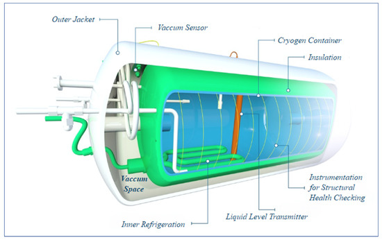
Figure 1.
An active refrigerated liquid hydrogen vacuumed pressure vessel cross-sectional drawing [35].
Whereas there are many similarities between the equipment used in the charging and discharging phases of different large-scale thermomechanical EES, the storage tanks are the primary components cost contributing to the discrepancy in total expenses. Hence, in the current study, a detailed technoeconomic investigation has been applied to cover the gap in the field of energy storage, especially for Liquid Air Storage (LAS).
2. Contribution of the Work
There are many similarities between the equipment used in the charging and discharging phases of different thermomechanical EES, such as PTES, LAES, and CAES, and the information, theory, rules, and specifications are very mature and widely available for turbines, compressors, heat exchangers, and pumps that are utilizable in the mentioned modes. On the other hand, due to the industry’s limited use of cryogenic processes, communication between researchers and manufacturers in this technology is insufficient compared to other cases. The equations established by the researchers have already had errors, especially in the economic estimates. In this article, based on the thermodynamics, governing codes, standards, and previous studies, more accurate equations are presented to estimate the volume of the cryogenic tank and the cost of its construction and installation. The equation extracted after validation is used in the study of the storage unit of an LAES plant integrated with a combustion chamber based on a commercial CAES power plant and the techno-economic evaluation of the storage unit of an adiabatic LASE power plant.
3. Problem Definition
An LAES plant comprises four parts: 1—Charging phase, 2—Storage unit, 3—TES farm, and 4—Discharging phase, as observable in Figure 2. As shown in Figure 2, compressors, heat exchangers, cryogenic expanders, and air gas separators are included in the charging process. Second, the TES unit includes two tank farms for cold and hot storage. Third, a double flat bottom container storage tank with accessories such as a ventilation system and insulation package forms the liquid air storage (LAS) unit. Finally, the charging part includes the expander part, the cryogenic pump, a cold recovery heat exchanger, and a recuperator.
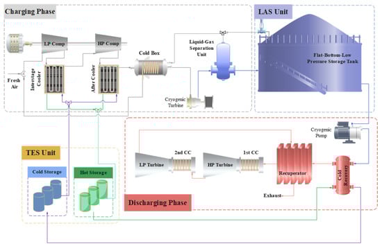
Figure 2.
Schematic diagram of an LAES plant integrated with combustion chambers.
4. Low-Pressure Liquid Air Storage
Flat-bottom storage tanks are categorized according to the maximum operating temperature and pressure of the vapor accumulated in the tank above space. If the maximum pressure is below 18 kPa, containers are typically engineered and assembled per API 650 regulation as flat-bottom cylindrical containers with cone roofs [36]. If the internal design pressure surpasses 18 kPa, tanks are usually engineered, fabricated, and inspected as flat-bottom cylindrical containers with dome roofs per API 620 [37]. The API has published API 625 code for cryogenic temperatures with a pressure range similar to API 620 [38] specification. When the liquid storage conditions surpass the API limits listed above, the American Society of Mechanical Engineers (ASME) codes and specifications are functional for cryogenic tank engineering, and tanks are observable in spherical or flared configuration, which is out of the scope of the current investigation. Hence, when a low-pressure cryogenic tank is under evaluation and engineering, the maximum allowable pressure for the tank should not exceed a pressure of 1.03 bars.
The API has classified the flat bottom storage tank into single, double, and completed-constraint storage systems, as shown in API 625 code [38].
The single-constraint design includes a sealed liquid and vapor container. It may be a single-wall liquid and vapor-proof tank or a storage system consisting of an inner and outer receptacle. Depending on applications, it may be engineered and fabricated in four variations as if only one internal container is required to hold the liquid. Another vessel is assumed to maintain the annular space insulation system. Figure 3 shows a single-constraint cryogenic tank doubled-wall manufactured from steel material.
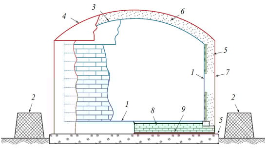
Figure 3.
Schematic of a single-constraint double-wall cryogenic tank, where the primary container is of steel material; 1—Main liquid vessel, 2—Safety dyke, 3—Cryogenic temperature roof, 4—Purge gas container, 5—foundation, 6—Insulation layer, 7—Purging gas shell, 8—floor insulation, 9—Outer bottom purge gas containment [38].
The double-constraint system comprises a liquid and vapor-sealed main tank assembled inside another container. The secondary vessel is arranged in two configurations to hold the liquid contents of the main container in case of leakages, see Figure 4. However, the outer walls do not intend to control or contain vapors from leaks. The completed-constraint storage tanks consist of primary and secondary liquid-tight containers. Both independently can contain the cryogen and control the vapor release in case of a leak from the primary vessel. The full constraints of the pressure vessel design are shown in Figure 5.
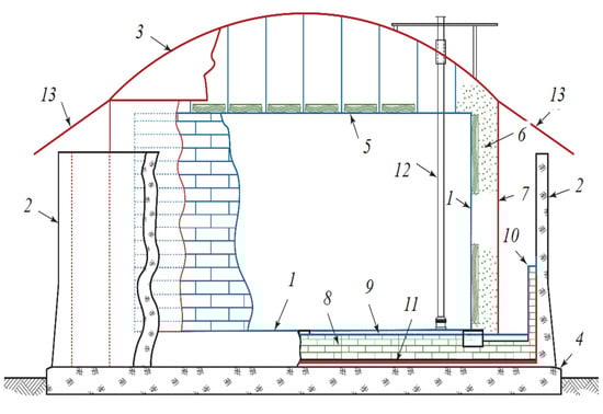
Figure 4.
Schematic of a double-constraint double-wall cryogenic tank, where the liquid and vapor receptacle is of steel material; 1—Main liquid vessel, 2—Safety dyke, 3—Warm zone, 4—Foundation, 5—Suspended deck, 6—Annular area insulation, 7—Warm area outer shell, 8—Floor insulation, 9—Secondary liquid vessel, 10—Thermal safety, 11—Moisture vapor barrier, 12—Pump column, 13—Precipitation guard [38].
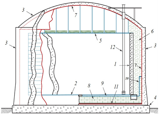
Figure 5.
Schematic of a complete-constraint double-wall cryogenic tank, where the liquid, vapor receptacle, and roof are of concrete material; 1—Main liquid vessel, 2—Tank bottom, 3—Secondary vessel, 4—Foundation, 5—Balanced surface, 6—Annular area insulation, 7—Vapor container, 8—Floor insulation, 9—Secondary liquid vessel, 10—Thermal safety, 11—Moisture vapor barrier, 12—Pump column [38].
The application of the tank’s configuration is based on the risk assessment evaluated by the project’s owner. The double constraint system is applicable when the liquid is only hazardous via splitting on the ground. In cases when vapor leakage is also dangerous, the complete storage system provides a safe envelope.
5. Materials and Methodology
In the present study, a steady-state simulation by Engineering Equation Solver code has been implemented. The following assumptions and limitations are considered:
- The air is real and dry;
- The efficiency of turbomachinery is constant in off-design and design conditions [39];
- The ambient and source pressure and temperature are 101 kPa and 20 °C, respectively;
- The pressure loss of piping is negligible;
- The air leakage from the UG storage is negligible [40];
- The heat losses and air leakage from the AG storage are considered in the LAS capacity calculation;
- The isentropic efficiency of rotary equipment is considered fixed in the current evaluation’s thermodynamic range;
- The time of charging and discharging is 8 and 2 h, respectively;
The validation is established on the work done by Soltani et al. [40]. The calculation for evaluating the discharge phase, including the heat exchangers, turbine sections, and combustion chamber, is conducted based on Huntorf [41], the first available commercialized plant.
Given that this study attends to solving the existing relations’ shortcomings in estimating the capacity of LAS and evaluating its cost, an accurate, comprehensive, and traceable method based on the API standard has been offered. In the end, a unique equation for approximating the total volume of the LAS per power is presented, and the cost relation per LAS volume has been modified. The solution process is depicted in the following flowchart, Figure 6.
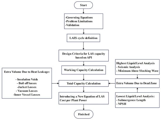
Figure 6.
Solution flowchart for estimating the LAS capacity and cost.
6. Validation
As discussed in Section 7.1, the LAS capacity depends on the output power; therefore, the LAS unit and discharge phase is only evaluated here. Accordingly, an investigation has been done on different types of power plants to increase the energy density of a well-known commercialized plant [29]. Since it is estimated that the destination would be established by applying LAS technology instead of compressed air storage (CAS), an LAES plant presented by Nabat et al. [39] is used to validate the working capacity estimation. However, the LAS capacity of the mentioned study has altered, as shown in Section 7.1 for the remained of air gas in LAS. Furthermore, for the rest of the equipment and process of the discharge phase, the Huntorf plant properties have been utilized and simulated. In Table 3, the result of validation is observable. As shown, the solution is well accompanied by the former studies.
Table 3.
Validation of current simulation with former evaluations.
7. Techno-Economic Calculations
Cryogenic tanks are engineered near the normal boiling point of the stored liquid, taking into consideration operational and safety concerns. Accordingly, any heat leakage and pressure reduction may cause liquid evaporation. The heat leakages cause tank safety trouble, which is solvable by installing ventilation systems. As a positive effect, the air pressure reduction, mainly during unloading, prevents the tank from a vacuum condition [42]. The capacity selection of liquid energy storage of an LAES plant is related to the amount of generated power related to energy management plus extra volume required for freeboard and heel [43], heat leakages from insulation voids and lost vacuum [34], and boil-off losses [32].
LAS integrated with a power plant produces power by evaporating the refrigerant air pumped into the expansion section. If its temperature at the inlet to the turbine is assumed to be constant, the required volume of the tank directly relates to the air mass flow. Therefore, different sizes of a particular LAS can be evaluated by varying the mass flow rate. Furthermore, given that the tank operates near the boiling temperature [42], any reduction in the tank pressure induced by liquid discharge causes a small portion to vaporize, which prevents vacuum occurrence and causes constant pressure conditions for the tank during the emptying process.
The thermodynamic conditions of the stored fluid at the beginning and end of the discharging process are observable in the T-S diagram; see Figure 7. As noticeable in a complete discharge cycle, the process between states A and B, corresponding to the beginning and end of power generation, is approximately constant pressure.
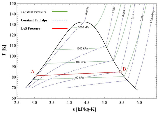
Figure 7.
T–S properties diagram of air, presenting the thermodynamic condition of the tank in complete (A) and empty condition (B).
7.1. Tank Working Capacity
Given constant pressure and temperature for A/B as liquid/gas condition, the total workable volume of cryogen is calculated as follows:
Via the equations mentioned above, the workable liquid is calculable. The workable volume of cryogen in a tank is the region between the lowest operating liquid Level (LLL) and highest operating liquid Level (HLL), as shown in Figure 8.
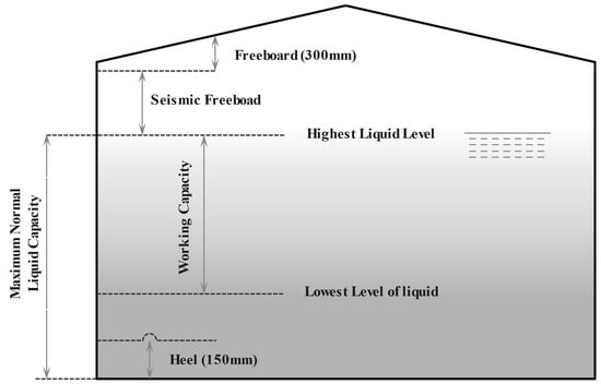
Figure 8.
The schematic of the mandatory levels to be observed in a cryogenic tank.
The extra volume that should be added to the workable tank capacity is the additional volume due to dead zones and heat leakages. Generally, there are two dead zones: the ullage or freeboard and the intact liquid due to suction condition and piping, which should be added to the workable capacity to select the right tank size. Heat leakage divides into two primary forms: vacuum and body deficiency and boil-off [44] losses. The heat may penetrate from insulation voids, inner container to outer jacket connections [34], losses vacuum, or inner vessel deficiencies. All of the heat leakages and gas venting to the atmosphere should be considered a percentage of the working volume of the tank.
7.2. Extra Volume Due to Dead Zone
As explained above, the dead zone includes the minimum space required for 1-liquid suction and 2-ullage or freeboard.
7.2.1. Highest Liquid Level
Zone Majumdar et al. [43] reported that a freeboard with a height of 85%, which is roughly around 94% of the total volume, is listed by manufacturers in their technical catalogs as the superior dead zone for sale in commercial applications [45] to cover the initial vaporizing named ullage. The American petroleum institute (API) has some codes and standards, API standards 620 [37], 625 [38], and 650 [36], for low-pressure liquid tanks to compensate for the seismic load and overfill protection margin. In the mentioned documents, the API recommends a sufficient freeboard for overflow and seismic load protection (Please see Appendix L of API 620 and 650).
According to Table 5E of Annex E of the API 650, by assuming the highest impact factor of 1.5, the formulation is as follows:
The height of the sloshing wave above the highest tank level, δs, is calculated as the equation below:
δs = 0.42 D·Af
D is the tank’s nominal diameter, and the sloshing Acceleration coefficient, Af, obtains as follows:
TC is the natural period of the sloshing mode of cryogen, calculated as follows:
H and D are the height and diameter of the selected tank.
TL is the regional-dependent shift time for a more extended earth movement of SUG III equal to 4 s.
S0 is the spectral response acceleration parameter at a period of zero seconds.
Sl is the spectral response acceleration parameter at a period of one second.
SS is a spectral response acceleration parameter at short periods.
Fa is the acceleration-based factor for installation conditions.
Fv is a velocity-based factor for installation conditions.
The results have been obtained from the available data on the United States Geological Survey (USGS) website for a presumed location employing the 2018 values [46].
According to [37], additional shell height shall be added above the sloshing wave height equal to 300 mm [37]. Therefore, the highest practical liquid level obtains from the following formula:
7.2.2. Lowest Liquid Level
The suction of liquid from a storage tank by pumping requires precise engineering evaluation. The system should be observed integrated from the storage to the consumers. The assessment of an entire pump station includes the following: 1—determination of the pump duty point, which is the intersection of the pumping curve and system losses; 2—suction and discharge pipe sizing; 3—intake design; and 4—net positive suction head (NPSH) calculation [47]. The intake design is related to the pipe configuration in the vessel, described in detail in API standards, and the submergence length, which affects tank capacity.
After calculating the required submergence length and NPSH plus 150 mm, as the unusable volume of liquid called heel in references [38] is a part of HLLL, the HLLL thus accounts for the distance from the level for pump-safe operation and the tank bottom, calculated as follows:
Submergence Length
In intake design, the principal parameter affecting the tank capacity is the submergence length [48]. The calculated submergence length prevents the formation of a gas funnel in the suction nozzle, causing vortex shedding and pump instabilities [49]. The submergence length, calculated from the flow rate and pipe size, is the minimum length between the suction nozzle and liquid surface, preventing vortex shedding [47].
The submergence length for a suction nozzle calculates from the following equation:
S, FrD, and D symbols are the submergence length, fraud number, and nominal pipe size.
NPSH
The second parameter is the net positive suction head (NPSH). Since the cryogens are stored near atmospheric pressure and are pumpable at approximately their boiling point, the only positive parameter in increasing the available NPSH is the liquid level above the suction nozzle [50].
The available NPSH is calculated from the following equation:
where the first term relates to the static head, and the second term strikes for head loss.
Generally, low-capacity pumps need lower NPSH, and higher-capacity pumps require a higher amount of NPSH for proper pump function. According to the high flow rate considered in the present work, about 1700 cubic meters per hour, commercial cryogenic centrifugal pumps need an NPSH of about 2 m [51]. Given that the available NPSH should be larger than the required one, considering one meter for suction pipe dynamic losses, the tank shall be 3 m extended in height to avoid taking suction instabilities.
7.3. Extra Volume Due to Heat Leakage
From the heat leakage point of view, the storage tanks could be classified into active and passive refrigerated systems. Active refrigerated tanks benefit from the zero-boil-off concept. In this system, installing a refrigerator in the storage covers heat leakage losses [52] but consumes a small portion of the plant-generated power. As the passive or unrefrigerated system shows, heat leakage must be factored into the final storage capacity.
7.3.1. Passive Refrigerated System
The vessel losses significantly depend on the time of storage. For instance, Swanger [42] showed that during the space shuttle 30 years schedule, approximately 54% and 32% of the total liquid hydrogen and oxygen burnt in the primary motor. This statement indicates that the liquid storage tanks have adequate shelf time, but the extra volume should be considered to cover the losses. Partridge et al. showed 6% and 13% cryogenic losses per 6 months for liquid oxygen and hydrogen, respectively [53]. Given that the loss of liquid also reduces the height needed for the proper suction, 6% extra of workable and LLL volume is acceptable for heat leakage coverage.
7.3.2. Active Refrigeration
The use of active refrigeration controls the tank pressure without the need for venting. In this case, the refrigeration system regularly removes the heat that has leaked into the inner container; see Figure 1. Plachta et al. [54] evaluated the active refrigeration over an 11 m3 spherical tank for liquid nitrogen. They found that for the cryogenic tank with specified insulation, 1.14 w per square meter of heat should be removed by cooling to prevent the air gas state from venting. Swanger [42] investigated the application of active refrigeration on a liquid hydrogen tank. For a full tank, they found that there is 1.36 w per square meter heat leakage for removal.
7.4. Total Capacity
The final estimation of commercial tank purchasing obtained from adding the extra capacities due to hydraulic and thermodynamic effects on the working volume is as follows:
7.5. Plant Energy Density
The energy density of an EES is the amount of energy that can be stored in the system relative to its volume. It is usually represented in kilowatt-hours per capacity required for storage (kW·h/m3).
7.6. Cryogenic Tank Cost
The total capital cost for the utilization of a cryogenic tank may be divided into purchasing and installation costs. The procedure of [55] applies to the purchasing price finalization in the present study. With a known equipment cost and size, the purchasing price may be normalized as follows:
Given that the costs from various sources are old and shall evolve up to date with an everyday basis named cost indices as follow:
8. Result and Discussion
8.1. LAS Capacity
The capacity of the tank is calculated via Equations (13)–(17) versus difference power generation and is depicted in Figure 9. As shown in the figure, for a fixed intake condition, the tank’s total capacity has approximately become more than one and a half times larger compared to the working volume required for around 300 MW of power production, which is the range of a well-proven commercialized CAES plant [41]. Given that the volume required for the proper operation of a storage tank is relatively constant, a larger storage tank has more significant time and cost advantages. However, smaller pumps may apply a smaller NPSH and, therefore, a lower HLLL.
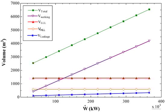
Figure 9.
The Cryogenic tank capacity calculation per power production.
As observable from Table 4, the extra capacity required due to heat leakage and dead zone with a constant pump required NPSH is higher for smaller LAS, which is getting lower for large LAS. Therefore, using LAS instead of CAS is a better choice for a power plant with a more than 200 MW production capacity. However, low air fluidization efficiency is a problem. As understood from Figure 10, a portion of any additional volume is reduced due to dead zones, heat leakage, and the workload required at more significant power outputs.
Table 4.
Results for the different extra volumes that are required for the storage of liquid in specified output power. Letter (a) indicates the power applied for black starts in the Huntorf CAES plan.
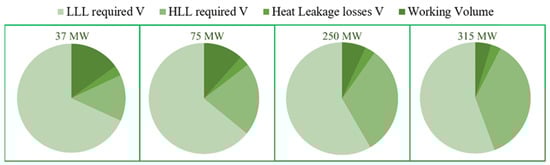
Figure 10.
The portion of the total volume that is occupied by various mandatory terms.
Calculations show that the volume for LAS needed to store the energy for the black-start solution, as indicated in the Huntorf plant, is 5482 cubic meters. Accordingly, purchasing the proper storage capacity, based on the availability on the market and advised dimensions with H/D = 0.8 [56], for a plant with 320 MW output power, 432 kg/s of mass flowrate, and discharging time of 2 h, a 6000 m3 tank with a diameter and height of 21.5 and 17 m is recommended.
8.2. Energy Density
Studies show that to increase the productivity and efficiency of CAES and LAES, apart from the area required for storing liquid and compressed air, they have more space for accumulating additional hot and cold exergy. Adiabatic CAES requires TES to recover condensation heat during charging and deliver it to the system during electricity generation [57]. Thus, an adiabatic LAES, in addition to recovering excess thermal energy during charge time, requires storing the cold exergy of the pumped liquid during production to increase the liquefaction of charge time [58].
Accordingly, the summation of mandated room for TES farm striking cold exergy and LAS, the required storage space for an adiabatic LAES is attainable. Nabat et al. [39], showed that the cold exergy could be recuperated with the assistance of cold methanol and propane with a capacity of 2800 m3. Hence, compared to CAS, the volume required to store energy reduces by about 35 times. However, the plant RTE may reduce by considering the liquefaction in the charging process.
8.3. Cost of LAS
This section introduces a more technical and practical equation for the cost estimation of a LAS than the previous equation used in research. The cost estimation of a storage tank should mainly include storage tank purchasing, pump, piping, safety equipment, foundation preparation, and setting cost [59].
The purchasing cost of a storage tank, accessories, and the cryogenic pump has been introduced in [60] as follows, where the cost of installation is not considered:
Presuming other costs, such as setting and civil work [61], the price of using the cryogenic tank is as follows:
Finally, updating Equation (22) for installation and foundation costs gives a new recommended formula for assuming the effect of the LAS cost in a whole plant economic study as follows:
The cost mentioned above should be updated for 2022 according to Equation (21).
The cost of purchasing and installing cryogenic tanks is observable versus various generated power generated in Figure 11. The graph shows the total and working tank capacity cost with Equation (24) and the old formula, Equation (22). As shown, the new and old cost ratio at higher tank capacities is getting lower because of the constant freeboard and suction requirements by standards and theory, evaluated in section 0.
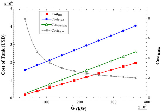
Figure 11.
The cost of the cryogenic tank with total and working capacity by the old and new equation.
The cost ratio shows its importance because, in the previous works, with an output power of 52 MW, a discharge time of 3 h, and a mass flowrate of 54.07 kg/s, the share of the cryogenic storage cost in the plant was 1.01% [39]. Employing the comprehensive equation for the total volume, Equation (18), and the recommended formula for cost, Equation (24), the new cost for the LAS is seven times large comparatively. Hence, the share of LAS cost in the total economic study becomes more than six times larger than in the previous work. As shown in Figure 11, the error of not applying the extra volume due to dead zones and heat leakage and the costs for installation in the total cost calculation is reducing with the increase of output power.
9. Conclusions
LASE and CAES plants were investigated from the discharge point of view, especially the energy storage unit, where the uncertainty of the previous research and the lack of comprehensive rules available for the techno-economic evaluation of LAS for the estimation of the cryogenic storage unit is perceptible. Accordingly, a classification of low-pressure storage tanks related to cryogenic storage and design criteria was presented, extracting from standards; therefore, a most compatible window was introduced for engineering and further assessments.
In the current investigation, after validation of the results, based on the thermodynamic theory of tanks, governing codes, standards, and previous studies, more accurate equations were presented to estimate the volume of the cryogenic tank and the related purchasing and installation cost. A technical evaluation and review of past research showed that the volume demanded to store a cryogen should include the required capacity to cover the unworkable product, heat leakages, and dead zones. Thus, a comprehensive equation, assuming the working and extra volumes, was presented in a single equation, as demonstrated in Section 7.4. Similarly, since the previously employed cost equations only included the purchasing cost, the cost of installation and civil works was counted based on the purchasing cost, forming a single cost equation, as presented in Section 7.4.
According to the mentioned statements, outcomes are summarized as follows:
- Based on the Huntorf plant properties, an LAES plant integrated with combustion was simulated and investigated from the discharging viewpoint. Calculations revealed that the volume of LAS required when substituting with CAS was 5482 cubic meters. Accordingly, when purchasing the appropriate storage capacity, based on the market availability and recommended dimensions, a 6000 m3 tank is selectable. Moreover, comparative assessments indicated that the space required to store energy carriers and cold TES substances is reduced by about 35 times to that of CAES.
- The comparison of the current approach with an adiabatic LAES plant was implemented to discover the misconceptions in the employment of equations that only contain purchasing terms. Results displayed that the share of LAS cost in the total economic study became more than six times larger than what was obtained in the forenamed work. The significant error was mainly due to the single-aspect cost equation and failure to assume the required capacity for heat leakage and dead zones.
Consequently, the accuracy of calculations and analyses of energy storage related to cryogenic tanks is expected to be increased by utilizing the expressed equations.
Author Contributions
H.J.: Conceptualization, Methodology, Simulation, Investigation, Validation, Writing—original draft preparation, Visualization, Methodology. M.S.: Investigation, Visualization, Theoretical Analysis, Project administration, Analysis, Writing—review and editing. J.N.: Investigation, Theoretical Analysis, Analysis, Writing—review and editing. All authors have read and agreed to the published version of the manuscript.
Funding
This research received no external funding.
Data Availability Statement
Data supporting the findings of this research can be provided based on the reasonable request of the authors.
Conflicts of Interest
The authors declare no conflict of interest.
Nomenclature
| Acronyms | Symbols | Subscript | |||
| API | American Petroleum Institute | A | Area, m2 | 0 | Zero Seconds |
| ASME | American Society of Mechanical Engineers | D | Diameter, m | A | Acceleration |
| CAES | Compressed Air Energy Storage | F | Installation Condition Factor | C | Compressor |
| CAS | Compressed Air Storage | H | Head, m | C | Sloshing Mode Due to Natural Period |
| CC | Combustion Chamber | I | Irreversibility, kJ/kg | D | Diameter |
| CT | Cryogenic Tank | L | Length, m | El | Electricity |
| EES | Electrical Energy Storage | Mass Flow Rate, kg/s | I | Inlet | |
| HLL | Highest Liquid Level | N | Number | L | Long Period |
| HP | High Pressure | P | Pressure, kPa | L | Long Period Earth Movement |
| LAES | Liquid Air Energy Storage | R | Radius, m | Max | Maximum |
| LAS | Liquid Air Storage | S | Spectral Response, m/s2 | Min | Minimum |
| LLL | Lowest Liquid Level | T | Temperature | O | Outlet |
| LP | Low Pressure | V | Volume, m3 | P | Pump |
| NPSH | Net Positive Suction Head | W | Work, kJ | S | Isentropic |
| PE | Purchased Equipment | Work Input Rate, kW | S | Short Period | |
| PHES | Pumped Hydro Energy Storage | Z | Compressibility Factor | T | Turbine |
| PTES | Pumped Thermal Energy Storage | Ρ | Density, kg/m3 | Th | Thermal |
| Pur | Purchased | v | Velocity | ||
| RTE | Round Trip Efficiency | Greek Letters | V | Volume | |
| TES | Thermal Energy Storage | η | Isentropic Efficiency | ||
| TRL | Technology Readiness Level | δ | Height of the Sloshing Wave | ||
| USGS | United States Geological Survey | ||||
References
- Mas, J.; Rezola, J.M. Tubular design for underwater compressed air energy storage. J. Energy Storage 2016, 8, 27–34. [Google Scholar] [CrossRef]
- Das, C.K.; Bass, O.; Kothapalli, G.; Mahmoud, T.S.; Habibi, D. Overview of energy storage systems in distribution networks: Placement, sizing, operation, and power quality. Renew. Sustain. Energy Rev. 2018, 91, 1205–1230. [Google Scholar] [CrossRef]
- Luo, X.; Wang, J.; Dooner, M.; Clarke, J. Overview of current development in electrical energy storage technologies and the application potential in power system operation. Appl. Energy 2015, 137, 511–536. [Google Scholar] [CrossRef]
- Argyrou, M.C.; Christodoulides, P.; Kalogirou, S.A. Energy storage for electricity generation and related processes: Technologies appraisal and grid scale applications. Renew. Sustain. Energy Rev. 2018, 94, 804–821. [Google Scholar] [CrossRef]
- Mazloum, Y.; Sayah, H.; Nemer, M. Exergy analysis and exergoeconomic optimization of a constant-pressure adiabatic compressed air energy storage system. J. Energy Storage 2017, 14, 192–202. [Google Scholar] [CrossRef]
- Matos, C.R.; Carneiro, J.F.; Silva, P.P. Overview of Large-Scale Underground Energy Storage Technologies for Integration of Renewable Energies and Criteria for Reservoir Identification. J. Energy Storage 2019, 21, 241–258. [Google Scholar] [CrossRef]
- Chen, L.; Wang, Y.; Xie, M.; Ye, K.; Mohtaram, S. Energy and exergy analysis of two modified adiabatic compressed air energy storage (A-CAES) system for cogeneration of power and cooling on the base of volatile fluid. J. Energy Storage 2021, 42, 103009. [Google Scholar] [CrossRef]
- Aneke, M.; Wang, M. Energy storage technologies and real life applications—A state of the art review. Appl. Energy 2016, 179, 350–377. [Google Scholar] [CrossRef]
- Stenzel, P.; Linssen, J. Concept and potential of pumped hydro storage in federal waterways. Appl. Energy 2016, 162, 486–493. [Google Scholar] [CrossRef]
- Yang, C.; Wang, T.; Li, Y.; Yang, H.; Li, J.; Qu, D.; Xu, B.; Yang, Y.; Daemen, J.J.K. Feasibility analysis of using abandoned salt caverns for large-scale underground energy storage in China. Appl. Energy 2015, 137, 467–481. [Google Scholar] [CrossRef]
- Farres-Antunez, P.; Xue, H.; White, A.J. Thermodynamic analysis and optimisation of a combined liquid air and pumped thermal energy storage cycle. J. Energy Storage 2018, 18, 90–102. [Google Scholar] [CrossRef]
- Alami, A.H. Mechanical Energy Storage for Renewable and Sustainable Energy Resources; Springer International Publishing: Cham, Switzerland, 2020. [Google Scholar] [CrossRef]
- Yu, Q.; Wang, Q.; Tan, X.; Fang, G.; Meng, J. A review of compressed-air energy storage. J. Renew. Sustain. Energy 2019, 11, 042702. [Google Scholar] [CrossRef]
- Huang, B.; Qiu, X.; Wang, W.; Li, H.; Zhou, W. Overview of research situation and progress on compressed air energy storage technology. In IOP Conference Series: Earth and Environmental Science; IOP Publishing: Bristol, UK, 2019; Volume 295. [Google Scholar] [CrossRef]
- Kantharaj, B.; Garvey, S.; Pimm, A. Compressed air energy storage with liquid air capacity extension. Appl. Energy 2015, 157, 152–164. [Google Scholar] [CrossRef]
- Al-Ibrahim, A.M.; Varnham, A. A review of inlet air-cooling technologies for enhancing the performance of combustion turbines in Saudi Arabia. Appl. Therm. Eng. 2010, 30, 1879–1888. [Google Scholar] [CrossRef]
- Zohuri, B. Cryogenics and Liquid Hydrogen Storage. In Hydrogen Energy; Springer: Berlin/Heidelberg, Germany, 2019; pp. 121–139. [Google Scholar] [CrossRef]
- Damak, C.; Leducq, D.; Hoang, H.M.; Negro, D.; Delahaye, A. Liquid Air Energy Storage(LAES) as a large-scale storage technology for renewable energy integration—A review of investigation studies and near perspectives of LAES. Int. J. Refrig. 2019, 110, 208–218. [Google Scholar] [CrossRef]
- Huang, Z.; Zhang, S.; Yang, R.; Wu, X.; Li, R.; Zhang, H.; Hung, P. A review of liquid nitrogen fracturing technology. Fuel 2020, 266, 117040. [Google Scholar] [CrossRef]
- Adams, C.; Alrashed, M.; An, R.; Anthony, J.; Asaadi, J.; Ashkenazi, A.; Balasubramanian, S.; Baller, B.; Barnes, C.; Barr, G.; et al. A method to determine the electric field of liquid argon time projection chambers using a UV laser system and its application in MicroBooNE. J. Instrum. 2020, 15, P07010. [Google Scholar] [CrossRef]
- Lin, Y.; Mauro, J.C.; Kaur, G. Bioactive Glasses for Cancer Therapy. In Biomedical, Therapeutic and Clinical Applications of Bioactive Glasses; Woodhead Publishing: Sawston, UK, 2019; pp. 273–312. [Google Scholar] [CrossRef]
- Song, C.; Liu, Q.; Deng, S.; Li, H.; Kitamura, Y. Cryogenic-based CO2 capture technologies: State-of-the-art developments and current challenges. Renew. Sustain. Energy Rev. 2019, 101, 265–278. [Google Scholar] [CrossRef]
- Aziz, M. Liquid Hydrogen: A Review on Liquefaction, Storage, Transportation, and Safety. Energies 2021, 14, 5917. [Google Scholar] [CrossRef]
- Karabeyoglu, A. Mixtures of nitrous oxide and oxygen (Nytrox) as oxidizers for rocket propulsion applications. In Proceedings of the 45th AIAA/ASME/SAE/ASEE Joint Propulsion Conference & Exhibit, Denver, CO, USA, 2–5 August 2009. [Google Scholar] [CrossRef]
- Brown, S.M.; Sneyd, J.R. Nitrous oxide in modern anaesthetic practice. BJA Educ. 2016, 16, 87–91. [Google Scholar] [CrossRef]
- Pauletto, G.; Galli, F.; Gaillardet, A.; Mocellin, P.; Patience, G.S. Techno economic analysis of a micro Gas-to-Liquid unit for associated natural gas conversion. Renew. Sustain. Energy Rev. 2021, 150, 111457. [Google Scholar] [CrossRef]
- Zohuri, B. Cryogenic Equipment, Systems, and Applications. In Physics of Cryogenics; Elsevier: Amsterdam, The Netherlands, 2018; pp. 529–564. [Google Scholar]
- Wan, C.; Zhu, S.; Shi, C.; Bao, S.; Zhi, X.; Qiu, L.; Wang, K. Numerical Simulation on Pressure Evolution Process of Liquid Hydrogen Storage Tank with Active Cryogenic Cooling: Simulation numérique du processus d’évolution de pression du réservoir de stockage d’hydrogène liquide avec refroidissement cryogénique actif. Int. J. Refrig. 2023, in press. [CrossRef]
- Bijeta Nayak, B.; Jena, H.; Dey, D.; Kassaye Oda, B.; Chetia, A.; Kumar Brahma, S.; Bordoloi, T.; Chakraborty, D. Materials selection and design analysis of cryogenic pressure vessel: A review. Mater. Today Proc. 2021, 47, 6605–6608. [Google Scholar] [CrossRef]
- Aceves, S.M.; Petitpas, G.; Espinosa-Loza, F.; Matthews, M.J.; Ledesma-Orozco, E. Safe, long range, inexpensive and rapidly refuelable hydrogen vehicles with cryogenic pressure vessels. Int. J. Hydrogen Energy 2013, 38, 2480–2489. [Google Scholar] [CrossRef]
- Qiu, Y.; Yang, H.; Tong, L.; Wang, L.; Arrigoni, M.; Amirkhiz, S.; Czujko, T. Research Progress of Cryogenic Materials for Storage and Transportation of Liquid Hydrogen. Metals 2021, 11, 1101. [Google Scholar] [CrossRef]
- Fesmire’, J.E.; Sass’, J.P.; Nag, Z.; Sojourner, S.J.; Morris’, D.L.; Augustynowicz, S.D. Cost-Efficient Storage of Cryogens; American Institute of Physics: College Park, MD, USA, 2008. [Google Scholar]
- Hu, Y.-H.; Fueglistaller, R.; Myronakis, M.; Singh, D.; Pandey, A.; Singh, M.; Johnson, W.L.; Fesmire, J.E.; Heckle, K.W. Thermal performance of multilayer insulation: A review. IOP Conf. Ser. Mater. Sci. Eng. 2018, 396, 012061. [Google Scholar] [CrossRef]
- Asia Industrial Gases Association. Storage of Cryogenic Air Gases at Users’ Premises Storage of Cryogenic Air Gases at Users’ Premises Disclaimer; AIGA Guideline 030/13; Asia Industrial Gases Association: Singapore, 2013. [Google Scholar]
- Toray Advanced Composites, Consortium to Develop LH2 Tanks—Aerospace Manufacturing and Design. Available online: https://www.aerospacemanufacturinganddesign.com/article/toray-advanced-composites-consortium-develop-lh2-tanks/ (accessed on 8 November 2022).
- API Standard 650; Welded Tanks for Oil Storage. American Petroleum Institute: Washington, DC, USA, 2013.
- API Standard 620; Design and Construction of Large, Welded, Low-Pressure Storage Tanks. American Petroleum Institute: Washington, DC, USA, 2013.
- API Standard 625; Tank Systems for Refrigerated Liquefied Gas Storage from HIS. American Petroleum Institute: Washington, DC, USA, 2010.
- Nabat, M.H.; Soltani, M.; Razmi, A.R.; Nathwani, J.; Dusseault, M.B. Investigation of a green energy storage system based on liquid air energy storage (LAES) and high-temperature concentrated solar power (CSP): Energy, exergy, economic, and environmental (4E) assessments, along with a case study for San Diego, US. Sustain. Cities Soc. 2021, 75, 103305. [Google Scholar] [CrossRef]
- Jafarizadeh, H.; Soltani, M.; Nathwani, J. Assessment of the Huntorf compressed air energy storage plant performance under enhanced modifications. Energy Convers. Manag. 2020, 209, 112662. [Google Scholar] [CrossRef]
- Guo, C.; Pan, L.; Zhang, K.; Oldenburg, C.M.; Li, C.; Li, Y. Comparison of compressed air energy storage process in aquifers and caverns based on the Huntorf CAES plant. Appl. Energy 2016, 181, 342–356. [Google Scholar] [CrossRef]
- Swanger, A. Large Scale Cryogenic Storage With Active Refrigeration. Master’s Thesis, University of Central Florida, Orlando, FL, USA, 2018. Available online: https://stars.library.ucf.edu/etd/6379/ (accessed on 21 August 2022).
- Majumdar’, A.K.; Steadman, T.E.; Marone, J.L.; Sass, J.P.; Fesmire, J.E. Numerical Modeling of Propellant Boil-Off in a Cryogenic Storage Tank; American Institute of Physics: College Park, MD, USA, 2008. [Google Scholar]
- Khalil, K.M.; Ahmad, A.; Mahmoud, S.; Al-Dadah, R.K. Liquid air/nitrogen energy storage and power generation system for micro-grid applications. J. Clean. Prod. 2017, 164, 606–617. [Google Scholar] [CrossRef]
- 10m3 16bar Stationary Cryogenic Liquid Storage Tank Price For Hospital Center Oxygen Supply System—Buy Stationary Liquid Storage Tank, Stationary Cryogenic Liquid Storage Tank, 10m3 Cryogenic Liquid Storage Tank Price Product on Alibaba.com. Available online: https://www.alibaba.com/product-detail/10m3-16bar-Stationary-Cryogenic-Liquid-Storage_1600477846986.html (accessed on 23 September 2022).
- 2018 United States (Lower 48) Seismic Hazard Long-Term Model|U.S. Geological Survey. Available online: https://www.usgs.gov/programs/earthquake-hazards/science/2018-united-states-lower-48-seismic-hazard-long-term-model#data (accessed on 28 October 2022).
- Jones, G.M.; Sanks, R.L.; Tchobanoglous, G.; Bosserman, B.E. Pumping Station Design; Gulf Professional Publishing: Houston, TX, USA, 2008. [Google Scholar] [CrossRef]
- Yedidiah, S. Centrifugal Pump User’s Guidebook; Springer: New York, NY, USA, 1996; ISBN 9781461312178. [Google Scholar]
- Tsohas, J. Hydrodynamics of Shear Coaxial Liquid Rocket Injectors. 2009. Available online: https://search.proquest.com/openview/f34a05605e44694daf67aaada2e8c97b/1?pq-origsite=gscholar&cbl=18750 (accessed on 14 October 2022).
- Karassik, I.J.; Messina, J.P.; Cooper, P.; Heald, C.C.; Krutzsch, W.C.; Hosangadi, A.; Kittredge, C.P.; Fraser, W.H.; Marscher, W.D.; Boyadjis, P.A.; et al. Pump Handbook. 2008. Available online: https://books.google.com/books/about/Pump_Handbook.html?id=_HHYtQEACAAJ (accessed on 14 October 2022).
- Centrifugal Pumps—Nikkiso. Available online: https://www.nikkisoceig.com/product-categories/centrifugal-pumps/ (accessed on 14 October 2022).
- Plachta, D.W.; Johnson, W.L.; Feller, J.R. Zero boil-off system testing. Cryogenics 2016, 74, 88–94. [Google Scholar] [CrossRef]
- Partridge, J.K.; Partridge, J.K. Fractional consumption of liquid hydrogen and liquid oxygen during the space shuttle program. AIP Conf. Proc. 2012, 1434, 1765. [Google Scholar] [CrossRef]
- Plachta, D. Results of an Advanced Development Zero Boil-Off Cryogenic Propellant Storage Test; American Institute of Aeronautics and Astronautics (AIAA): Reston, VA, USA, 2004. [Google Scholar]
- Harnby, N.; Edwards, M.; Nienow, A. Mody and Marchildon: Chemical Engineering Process Design. Available online: https://chemeng.queensu.ca/courses/integratedDesign/Resources/documents/CEPDtxtCh16.doc (accessed on 2 October 2022).
- Agboola, O.O.; Akinnuli, B.O.; Kareem, B.; Akintunde, M.A. Optimum detailed design of 13,000 m3 oil storage tanks using 0.8 height-diameter ratio. In Materials Today: Proceedings; Elsevier: Amsterdam, The Netherlands, 2021; Volume 44, pp. 2837–2842. [Google Scholar]
- Hüttermann, L.; Span, R. Investigation of storage materials for packed bed cold storages in liquid air energy storage (LAES) systems. Energy Procedia 2017, 143, 693–698. [Google Scholar] [CrossRef]
- Hamdy, S.; Moser, F.; Morosuk, T.; Tsatsaronis, G. Exergy-based and economic evaluation of liquefaction processes for cryogenics energy storage. Energies 2019, 12, 493. [Google Scholar] [CrossRef]
- Geyer, W.B.; Wisuri, J. Handbook of Storage Tank Systems: Codes, Regulations, and Designs; CRC Press: Boca Raton, FL, USA, 2000; p. 347. [Google Scholar]
- Hu, Y.; Li, X.; Li, H.; Yan, J. Peak and off-peak operations of the air separation unit in oxy-coal combustion power generation systems. Appl. Energy 2013, 112, 747–754. [Google Scholar] [CrossRef]
- Loh, H.P.; Lyons, J.; White, C.W., III. Process Equipment Cost Estimation, Final Report. 2002. Available online: http://www.osti.gov/scitech//servlets/purl/797810-Hmz80B/native/ (accessed on 16 August 2022).


Disclaimer/Publisher’s Note: The statements, opinions and data contained in all publications are solely those of the individual author(s) and contributor(s) and not of MDPI and/or the editor(s). MDPI and/or the editor(s) disclaim responsibility for any injury to people or property resulting from any ideas, methods, instructions or products referred to in the content. |
© 2023 by the authors. Licensee MDPI, Basel, Switzerland. This article is an open access article distributed under the terms and conditions of the Creative Commons Attribution (CC BY) license (https://creativecommons.org/licenses/by/4.0/).