Article

Effect of KLT-40S Fuel Assembly Design on Burnup Characteristics

School of Nuclear Science and Technology, University of South China, Hengyang 421001, China
*
Authors to whom correspondence should be addressed.
Energies 2023, 16(8), 3364; https://doi.org/10.3390/en16083364
Submission received: 17 March 2023 / Revised: 6 April 2023 / Accepted: 11 April 2023 / Published: 11 April 2023
(This article belongs to the Special Issue Nuclear Engineering and Technology)

Abstract

:
The KLT-40S is a small modular reactor developed by Russia based on the KLT-40 reactor with two fuel assembly designs: a four-ring and a five-ring. Few studies have been published on fuel assembly and power-flattening designs for the KLT-40S. In this paper, the effects of different fuel assembly designs on burnup and power flattening are investigated. This paper compares the effects of the two fuel assembly designs of the KLT-40S on its burnup characteristics, analyzes the effects of fuel rod diameter on burnup characteristics, and conducts a computational study on the ideal power-flattening design. The results show that the five-ring fuel assembly design has better burnup characteristics than the four-ring fuel assembly design. At a fuel rod diameter of 0.62 cm, the optimal burnup lattice is obtained. The 15.84% + 19.75% power-flattening design (uranium enrichment in the innermost and outermost rings + uranium enrichment in inner rings) reduces the local power peaking factor of the five-ring fuel assembly below 1.11 throughout the lifetime. Therefore, the KLT-40S five-ring fuel assembly has better burnup characteristics, and its optimal burnup lattice is at the 0.62 cm fuel rod diameter. The use of power-flattening designs can effectively reduce the local power peaking factor.

1. Introduction

With the growing demand for energy and the increasing emphasis on environmental protection, nuclear energy has become a clean source of energy for all countries around the world [1,2]. Nuclear energy occupies an important place in the development of clean energy and can provide a reliable energy supply to the world’s population [3]. The International Atomic Energy Agency defines a reactor with an electrical power of less than 300 MWe as a small reactor [4]. The modular design and assembly of the nuclear steam supply system (NSSS) is known as “modular” [5]. Due to its modular design, the small modular reactors have the advantages of small size, convenient transportation, short construction period, high safety performance, and extensive use, which can meet the demand for flexible power generation around the world. Small modular reactors can also be used for nuclear power propulsion and floating nuclear power plants; they are valuable for maintaining marine safety, developing marine resources, and supplying power to remote coastal areas [6,7]. In recent years, the United States, Russia, and other countries are actively promoting the development and construction of small modular reactors. At present, there are approximately 20 kinds of small modular reactor designs around the world, and the small modular reactors have become an important direction for the future development of nuclear reactor technology.
Russia has extensive experience in nuclear reactor applications and has a unique physical design for reactors [8]. The computational study of its related physical design is helpful to advance the optimization of the physical design of small modular reactors. KLT-40S is a part of the small modular floating power unit (FPU) of the nuclear heat power plant developed by OKBM Afrikantov based on the KLT-40 reactor [9]. The KLT-40S is in Russia’s Akademik Lomonosov, the world’s first floating nuclear power station [10].
According to public information, two fuel assembly designs exist for the KLT-40S: four-ring and five-ring. Data provided by OKBM Afrikantov to the International Atomic Energy Agency show that various numbers of fuel rods are used in the KLT-40S fuel assembly (69, 72, and 75) [11]. Gadjah Mada University studied the KLT-40S core neutronic parameters using the four-ring fuel assembly (four rings of fuel rods arranged inside the fuel assembly) and a total of 69 fuel rods [12]. The National Research Tomsk Polytechnic University (Russia) [13,14], National Research Nuclear University (Russia) [15], and Singapore Nuclear Research and Safety Initiative [16] conducted computational studies using the KLT-40S five-ring fuel assembly (five rings of fuel rods arranged inside the fuel assembly), with 102 fuel rods in total. Differences in fuel assembly designs cause changes in geometric parameters and fuel loading; in turn, these changes affect the neutronic behavior of the fuel assembly, such as its neutron spectrum and macroscopic cross section, thereby affecting the lifetime, burnup depth, and fuel utilization of the fuel assembly. Few comparative studies have been published on the two KLT-40S fuel assembly designs.
In 1990, the Soviet government provided the Norwegian government with some reactor core design parameters for the reactor KLT-40 of the icebreaker Sevmorput. A group of Norwegian analysts used published data to develop a simple model of the KLT-40 core [17]. In the KLT-40 Norwegian model, the water-filled space between the fuel assemblies is larger than the water-filled space between the fuel rods inside the fuel assemblies, which can lead to a large power factor in the outermost ring of the fuel assemblies. The researchers suggested that the local power peaking factor of the fuel assembly could be reduced by decreasing the 235U enrichment in the outer ring of fuel rods and increasing the 235U enrichment in the two inner rings of fuel rods [17]. The KLT-40S, improved based on the KLT-40, may adopt a fuel assembly design with different arrangements of fuel enrichment (power-flattening designs) to flatten the power distribution in the fuel assembly. Few comparative studies have been conducted for the fuel assembly local power peaking factor, and the computational study of the possible power-flattening designs of the KLT-40S is beneficial to promote the design optimization of the small modular reactor power-flattening design [18].
For an analysis of the effects of different fuel assembly designs on the burnup characteristics and local power peaking factor of the KLT-40S fuel assembly, this paper presents a computational study on the reactor fuel assembly and power-flattening designs using the open-source Monte Carlo calculation program OpenMC [19]. First, the effects of the two fuel assembly designs on the fuel assembly lifetime, initial infinite multiplication factor kinf, and 235U utilization rate are compared, and the results show that the five-ring fuel assembly design has a 16.67% higher initial fuel loading, 21.31% longer lifetime, and 2.13% higher 235U utilization rate, and better burnup characteristics than the four-ring fuel assembly design. Then, with the five-ring fuel assembly design as the calculation model, the influence of different fuel rod diameters on the burnup depth is calculated and analyzed to study the tight-pitch lattice design concept. At a fuel rod diameter of 0.52 cm, the water–uranium ratio is optimal and the initial infinite multiplication factor kinf reaches a maximum value of 1.717. At a fuel rod diameter of 0.62 cm, the optimal burnup lattice is obtained, and the burnup depth and 235U utilization rate of the five-ring fuel assembly design reach their maximum values. Finally, the ideal power-flattening design for the KLT-40S fuel assembly is theoretically analyzed and computationally verified. The results show that the use of power-flattening designs can effectively reduce the local power peaking factor.

2. Materials and Methods

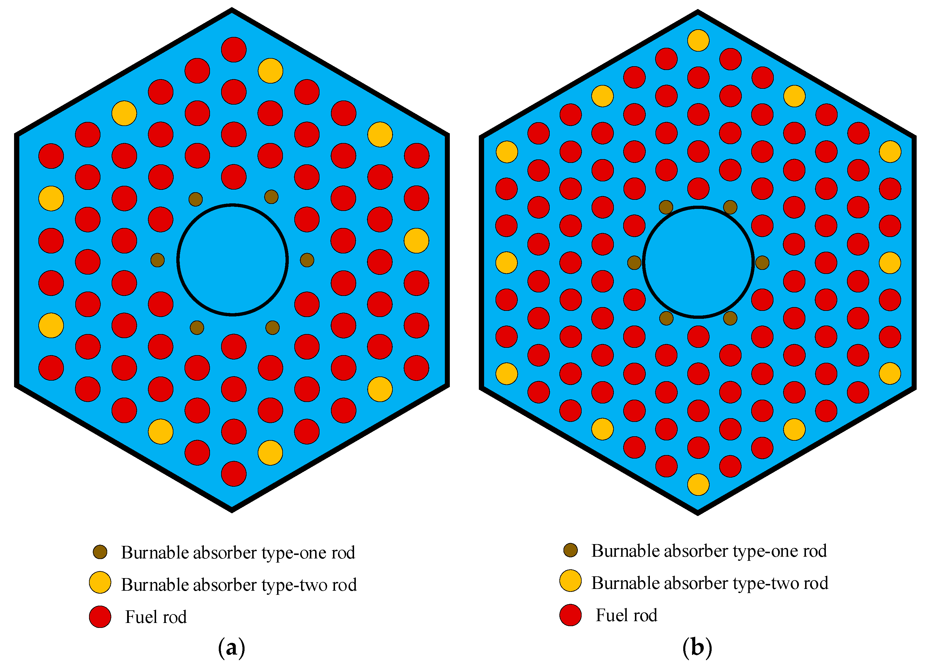
2.1. KLT-40S Fuel Assembly Designs

Russia has the characteristics of novel generation in nuclear reactor design, and has paid attention to expanding the improved reactor model in each generation of basic reactor type. The fuel assemblies and fuel rods of small reactors in Russia are basically arranged in a regular triangle lattice, the control rods are located inside the fuel assembly, and the fuel assembly contains two diameters of burnable absorber rods. These designs are embodied in the OK-900A, KLT-40S, RITM-200, and other nuclear reactors [20].
The active height of KLT-40S is 1.2 m and the equivalent diameter of the reactor core is 1.155 m. The 121 fuel assemblies are loaded into the reactor core in a regular triangle lattice at a distance of 10 cm. Two fuel assembly designs exist for the KLT-40S, namely, four-ring and five-ring designs, as shown in Figure 1. The four-ring fuel assembly contains four rings of fuel rods arranged inside the fuel assembly with a total of 69 fuel rods, and the five-ring fuel assembly contains five rings of fuel rods inside the fuel assembly with a total of 102 fuel rods.
Both fuel assembly designs share some characteristics. The flat width and thickness of the fuel assembly are 10 and 0.1 cm, respectively. Seven inner channels are reserved for the control rods, which are replaced by an inner cylindrical shroud with a diameter of 2.6 cm and a thickness of 0.05 cm. The fuel elements in the fuel assembly are arranged in a regular triangular lattice. The KLT-40S reactor is based on the civilian marine reactor KLT-40, and both fuel assembly designs use uranium dioxide in the aluminum–silicon matrix for fuel, with a fuel enrichment of 18.6%. This satisfies the Nuclear Non-Proliferation Treaty. The parameters of the KLT-40S fuel assembly and the aluminum–silicon matrix material are shown in Table 1 and Table 2, respectively.
The four-ring fuel assembly has 69 fuel rods, with a rod diameter of 0.68 cm and a rod spacing of 0.995 cm. The innermost ring of the fuel assembly has six burnable type I absorber rods, and the outermost ring has nine burnable type II absorber rods [21]. The five-ring fuel assembly has a more compact lattice design; there are 102 fuel rods inside the fuel assembly, with a fuel rod diameter of 0.62 cm and a rod spacing of 0.835 cm. The innermost ring of the fuel assembly has six burnable type I absorber rods, and the outermost ring has 12 burnable type II absorber rods. The fuel rod parameters of the two fuel assembly designs are shown in Table 3.

2.2. Power-Flattening Design

As Figure 1 shows, the water-filled space between the innermost and outermost rings is larger than the inner rings within the fuel assembly. Therefore, the neutrons in the innermost and outermost rings have a high probability of reacting with water, and the moderation of neutrons is enhanced. When the fuel rods within the fuel assembly adopt the same enrichment fuel, the neutrons in the innermost and outermost rings of the fuel assembly are more likely to fission react with the fuel than the fuel rods in other locations of the assembly, resulting in an unbalanced power distribution.
While keeping the fuel loading of the fuel assembly constant, the macroscopic cross-section at different locations inside the fuel assembly is adjusted by reducing the uranium enrichment in the innermost and outermost fuel rod rings and increasing the uranium enrichment in the other rings. The local power peaking factor of the fuel assembly can be effectively decreased. The five-ring fuel assembly design with the above power-flattening design is shown in Figure 2. The innermost and outermost rings of the KLT-40S fuel assembly are light fuel elements, and the inner rings of the fuel assembly are heavy fuel elements [22]. The parameters of the different power-flattening designs are shown in Table 4.

2.3. Calculation Procedure: OpenMC

OpenMC is an open-source Monte Carlo calculation program developed by members of the MIT Computational Reactor Physics Group [23]. OpenMC can model the reactors with complex materials and flexible geometries, and perform the burnup calculations for the reactors model. OpenMC can record and extract the neutron energy spectrum, nuclide contents, nuclear reaction rate, and other data during the calculations, which is beneficial for the theoretical analysis of the calculation results [24]. Various universities and some research institutions now use OpenMC for related development and computational research.

3. Results and Discussion

3.1. Effect of Fuel Assembly Design on Burnup

The KLT-40S reactor consists of 121 hexagonal fuel assemblies and has a thermal power of 150 MW. The burnup calculations for both KLT-40S fuel assemblies are without burnable poison at an average fuel assembly power of 1.23 MW. The results of the initial infinite multiplication factor, lifetime, and 235U utilization rate for the four-ring and five-ring fuel assemblies are shown in Table 5. Figure 3 shows the variations in kinf with the equivalent full power day (EFPD) for the two fuel assembly designs.
The calculation results show the following: (1) The initial infinite multiplication factors kinf of the four-ring and five-ring fuel assemblies are the same. (2) The five-ring fuel assembly design has a 16.67% higher initial fuel loading. The EFPD of the four-ring fuel assembly is 1220 days, whereas that of the five-ring fuel assembly is 1480 days, which is 260 days longer than that of the four-ring fuel assembly. (3) The 235U utilization rate of the five-ring fuel assembly at the end of its lifetime is 2.13% higher than that of the four-ring fuel assembly.
The main factors affecting the lifetime of a fuel assembly in the absence of burnable poison are the initial charge of the fissile nuclides and the conversion rate of the fissile nuclides during burnup [25]. The five-ring fuel assembly has 16.67% more initial fuel loading than the four-ring fuel assembly. As shown in Figure 4, compared with the four-ring fuel assembly, the five-ring fuel assembly has a harder neutron energy spectrum and weaker neutron moderation because of its more compact grid arrangement. As shown in Figure 5, the harder neutron energy spectrum facilitates the uranium–plutonium cycle and fissile nuclide conversion. Therefore, the EFPD of the five-ring fuel assembly reaches 1480 days, which is 21.31% longer than that of the four-ring fuel assembly, and the 235U utilization rate is higher.
In summary, the difference in the initial infinite multiplication factor kinf between the two fuel assembly designs for the KLT-40S is insignificant. The five-ring fuel assembly can load more fuel and has a longer EFPD and a higher 235U utilization rate. Therefore, it has better burnup characteristics than the four-ring fuel assembly. This paper follows up with a computational study using the KLT-40S five-ring fuel assembly as the model.

3.2. Effect of Fuel Rod Diameter on Burnup

With the KLT-40S five-ring fuel module as the calculation model, the tight-pitch lattice design within the fuel assembly is calculated and studied. With a constant width across the flats of the fuel assembly, a constant fuel element lattice pitch, and different fuel rod diameters, the burnup is calculated at an average fuel assembly power of 1.23 MW. Figure 6 shows the kinf curves of the KLT-40S five-ring fuel assembly with the EFPD at different fuel rod diameters. Figure 7 shows the kinf curves of the KLT-40S five-ring fuel assembly with burnup depth at different fuel rod diameters. Table 6 shows the calculated results of the fuel assembly at different fuel rod diameters.
Figure 8 shows the neutron energy spectra of the KLT-40S five-ring fuel assembly at different fuel rod diameters. With a decrease in the fuel rod diameter and an increase in the water-filled space within the fuel assembly, the neutron moderation increases, the neutron energy spectrum softens, and the neutron content in the thermal neutron region rises. However, as the fuel rod diameter decreases, the fuel loading in the fuel assembly falls; as the water content in the fuel assembly increases, the probability of the thermal neutrons being absorbed by the moderator water rises, and the utilization rate of the thermal neutrons decreases.
Figure 9 shows the variation in the initial infinite multiplication factor kinf with the fuel rod diameter. At the fuel rod diameter of 0.52 cm, the water–uranium ratio is optimal and the initial infinite multiplication factor kinf reaches a maximum value of 1.717. Figure 10 shows the fissile nuclide conversion ability of the fuel assembly at different fuel rod diameters. In the over-moderated lattice, the initial infinite multiplication factor kinf, fissile nuclide conversion ability, and maximum burnup depth increase with the fuel rod diameter. In the under-moderated lattice, the effect of an increase in the fuel rod diameter on the initial infinite multiplication factor kinf and fissile nuclide conversion ability is reversed. As the fuel rod diameter increases, the neutron energy spectrum hardens, the initial infinite multiplication factor kinf decreases, and the fissile nuclide conversion ability increases. Therefore, at a certain fuel rod diameter in the under-moderated lattice, the initial infinite multiplication factor kinf and fissile nuclide conversion ability are balanced and the fuel assembly reaches the maximum burnup depth.
Figure 11 shows the variations in the EFPD and the maximum burnup depth with fuel rod diameter. As the fuel rod diameter increases, the EFPD keeps increasing; the maximum burnup depth increases and then decreases. At the fuel rod diameter of 0.62 cm, the fuel assembly obtains the maximum 235U utilization rate and a maximum burnup depth of 145,861 MW·d/tU, which is 5700 MW·d/tU larger than that of the lattice with the optimal water–uranium ratio.

3.3. Power-Flattening Design

Power-flattening designs are studied for the KLT-40S five-ring fuel assembly using its optimal burnup lattice (0.62 cm fuel rod diameter). Burnup is calculated for the four power-flattening designs in Table 4 at an average fuel assembly power of 1.23 MW. The computed initial infinite multiplication factor, lifetime, and local power peaking factor are shown in Table 7. The curves of the burnup characteristics for the four different power-flattening designs are shown in Figure 12.
The calculation results show the following: (1) The initial infinite multiplication factors kinf of the four designs are the same. Because the assemblies have the same initial fuel loading, their EFPDs do not significantly differ. (2) The initial maximum local power peaking factor is 1.193 when the fuel assembly has an average enrichment of 18.6%. (3) The power-flattening designs effectively reduce the local power peaking factor.
Figure 13 shows the power distributions of the four power-flattening designs at the beginning of the fuel assembly lifetime. Figure 14 shows the neutron energy spectra at different locations in the fuel assembly. With an average fuel enrichment of 18.6%, the fuel assembly achieves the best neutron moderation in the innermost ring and the largest power factor of the innermost ring (up to 1.19). The local power peaking factor reduces from 1.19 to 1.14 when the fuel assembly uses the 17.4% + 19.1% power-flattening design. The local power peaking factor decreases from 1.19 to 1.09 when the fuel assembly uses the 15.7% + 19.8% or 15.84% + 19.75% power-flattening design.
Figure 15 shows the trend of the local power peaking factor during the fuel assembly lifetime. As shown in the figure, when the fuel assembly is designed with an average fuel enrichment of 18.6%, the local power peaking factor gradually decreases with burnup from 1.19. After 900 days of burnup, the local power peaking factor has a tendency to increase under deep burnup. Under the 17.4% + 19.1% power-flattening design, the local power peaking factor also decreases with burnup and increases toward the end of the lifetime. Under the 15.7% + 19.8% and 15.84% + 19.75% power-flattening designs, the local power peaking factor is less than 1.11 and maintained at approximately 1.10 throughout the lifetime. The lower the fuel enrichment of the innermost ring, the smaller the local power peaking factor at the beginning of the fuel assembly lifetime and the better the power-flattening effect. Because the fuel enrichment used in the KLT-40S does not exceed 19.75%, the 15.84% + 19.75% power-flattening design is the best arrangement of fuel enrichment.

4. Conclusions and Discussion

The KLT-40S is a typical small modular reactor design. The KLT-40S fuel assembly and power-flattening designs were calculated and analyzed in this paper. In this work, the burnup characteristics were compared under different fuel assembly designs, the effect of fuel rod diameter on burnup was analyzed, and a computational study was conducted on various power-flattening designs. The main conclusions are as follows:
(1)
The initial infinite multiplication factors, kinf, of the four-ring and five-ring fuel assembly designs are the same. However, compared with the four-ring fuel assembly, the five-ring fuel assembly has a 16.67% higher initial fuel loading, a significant lifetime improvement of 21.31%, and a 2% increase in the 235U utilization rate. Therefore, the KLT-40S five-ring fuel assembly has better burnup characteristics than the four-ring fuel assembly. This is the reason why most of the computational studies are conducted using the KLT-40S five-ring fuel assembly as the computational model.
(2)
At a fuel rod diameter of 0.52 cm for the five-ring fuel assembly, the water–uranium ratio is optimal and the initial infinite multiplication factor kinf reaches a maximum value of 1.717. With an increase in the fuel rod diameter, the fuel assembly lifetime increases, and the burnup depth increases and then decreases. At a fuel rod diameter of 0.62 cm, the burnup depth and 235U utilization rate of the five-ring fuel assembly reach their maximum values (optimal burnup lattice). Russia uses fuel rods with a diameter of 0.62 cm in the KLT-40S reactor, which proves that the country not only aims to extend the fuel assembly lifetime, but also to enhance fuel utilization. This provides some design concepts for the development of small modular reactors.
(3)
The use of a power-flattening design can effectively reduce the local power peaking factor. The lower the fuel enrichment of the innermost ring, the better the power-flattening effect and the smaller the local power peaking factor. Because the fuel enrichment used in the KLT-40S does not exceed 19.75%, the 15.84% + 19.75% power-flattening design is the best arrangement for fuel enrichment. Under the 15.84% + 19.75% power-flattening design, the local power peaking factor decreases from 1.19 to 1.09 at the beginning of the lifetime; it is less than 1.11, and remains at approximately 1.10 throughout the lifetime. This provides some guidance for the design of power-flattening for small modular reactors.
In this paper, burnup was calculated using a fuel assembly without burnable poison so that the fuel assembly had a large initial infinite multiplication factor. Burnable poison can effectively reduce the initial infinite multiplication factor. Follow-up studies can use burnable poison for reactivity shimming to achieve reactivity control. The combination of a burnable poison design and power-flattening design can ensure a smooth release of reactivity throughout the lifetime and obtain a smaller local power peaking factor.

Author Contributions

Z.Z.: conceptualization, methodology, writing—original draft. J.X.: methodology, formal analysis. N.D.: investigation. P.C.: software. Z.W.: validation, data curation. T.Y.: resources, writing—review and editing, supervision. All authors have read and agreed to the published version of the manuscript.

Funding

This research received no external funding.

Data Availability Statement

Data available on request.

Acknowledgments

We thank the NEAL Group from the University of South China for their help.

Conflicts of Interest

The authors declare no conflict of interest. All authors have read and agreed to the published version of the manuscript.

References

  1. Liu, Z.; Fan, J. Technology readiness assessment of small modular reactor (SMR) designs. Prog. Nucl. Energy 2014, 70, 20–28. [Google Scholar] [CrossRef]
  2. Locatelli, G.; Bingham, C.; Mancini, M. Small modular reactors: A comprehensive overview of their economics and strategic aspects. Prog. Nucl. Energy 2014, 73, 75–85. [Google Scholar] [CrossRef]
  3. Asif, M.; Muneer, T. Energy supply, its demand and security issues for developed and emerging economies. Renew. Sustain. Energy Rev. 2007, 11, 1388–1413. [Google Scholar] [CrossRef]
  4. Subki, H. Advances in Small Modular Reactor Technology Developments; INIS-XA—20M3048; International Atomic Energy Agency (IAEA): Vienna, Austria, 2020. [Google Scholar]
  5. Ingersoll, D.T.; Carelli, M.D. Handbook of Small Modular Nuclear Reactors; Woodhead Publishing: Cambridge, UK, 2020. [Google Scholar]
  6. Di Maio, F.; Bani, L.; Zio, E. The Contribution of Small Modular Reactors to the Resilience of Power Supply. J. Nucl. Eng. 2022, 3, 152–162. [Google Scholar] [CrossRef]
  7. Ghazaie, S.; Sadeghi, K.; Sokolova, E.; Fedorovich, E.; Shirani, A. Comparative Analysis of Hybrid Desalination Technologies Powered by SMR. Energies 2020, 13, 5006. [Google Scholar] [CrossRef]
  8. Reistad, O.; Ølgaard, P.L. Russian Nuclear Power Plants for Marine Applications; NKS-138; Nordic Nuclear Safety Research: Roskilde, Denmark, 2006. [Google Scholar]
  9. Polunichev, V.I. Prospects for the Utilization of Small Nuclear Plants for Civil Ships, Floating Heat and Power Stations and Power Seawater Desalination Complexes; IAEA-TECDOC-1184; International Atomic Energy Agency: Vienna, Austria, 2000. [Google Scholar]
  10. Lee, K.-H.; Kim, M.-G.; Lee, J.I.; Lee, P.-S. Recent Advances in Ocean Nuclear Power Plants. Energies 2015, 8, 11470–11492. [Google Scholar] [CrossRef] [Green Version]
  11. International Atomic Energy Agency. Available online: https://aris.iaea.org/PDF/KLT-40S.pdf (accessed on 1 April 2023).
  12. Fajri, D.F.; Agung, A.; Harto, A.W. The Study of Floating Nuclear Power Plant Reactor Core Neutronic Parameters Using Scale 6.1 Code. Int. J. Adv. Sci. Eng. Inf. Technol. 2020, 10, 1774–1783. [Google Scholar] [CrossRef]
  13. Baybakov, D.; Godovykh, A.; Martynov, I.; Nesterov, V. The dependence of the nuclide composition of the fuel core loading on multiplying and breeding properties of the KLT-40S nuclear facility. Nucl. Energy Technol. 2016, 2, 183–190. [Google Scholar] [CrossRef] [Green Version]
  14. Beliavskii, S.V.; Nesterov, V.N.; Laas, R.A.; Godovikh, A.V.; Bulakh, O.I. Effect of fuel nuclide composition on the fuel lifetime of reactor KLT-40S. Nucl. Eng. Des. 2020, 360, 110524. [Google Scholar] [CrossRef]
  15. Baatar, T.; Glazkov, O.V. Increasing burn-up of KLT-40S fuel by introduction of neptunium. J. Physics Conf. Ser. 2020, 1689, 012061. [Google Scholar] [CrossRef]
  16. Tiang, Z.H.; Xiao, S. Long-term reactivity control of accident tolerant fuel loaded marine small modular reactor using particle-type burnable poisons. Ann. Nucl. Energy 2021, 156, 108177. [Google Scholar] [CrossRef]
  17. Diakov, A.C.; Dmitriev, A.M.; Kang, J.; Shuvayev, A.M.; von Hippel, F.N. Feasibility of Converting Russian Icebreaker Reactors from HEU to LEU Fuel. Sci. Glob. Secur. 2006, 14, 33–48. [Google Scholar] [CrossRef]
  18. Oettingen, M.; Kim, J. Detection of Numerical Power Shift Anomalies in Burnup Modeling of a PWR Reactor. Sustainability 2023, 15, 3373. [Google Scholar] [CrossRef]
  19. Romano, P.K.; Horelik, N.E.; Herman, B.R.; Nelson, A.G.; Forget, B.; Smith, K. OpenMC: A state-of-the-art Monte Carlo code for research and development. Ann. Nucl. Energy 2015, 82, 90–97. [Google Scholar] [CrossRef] [Green Version]
  20. Zverev, D.L.; Pakhomov, A.N.; Polunichev, V.I.; Veshnyakov, K.B.; Kabin, S.V. RITM-200: New-generation reactor for a new nuclear icebreaker. Sov. At. Energy 2013, 113, 404–409. [Google Scholar] [CrossRef]
  21. Savitsky, D.E.; Kuzmin, A.V. The calculation of the campaign of reactor RITM-200. IOP Conf. Ser. Mater. Sci. Eng. 2021, 1019, 012057. [Google Scholar] [CrossRef]
  22. Naumov, V.; Gusak, S.; Naumov, A. Small nuclear power plants for power supply in arctic regions: Assessment of spent nuclear fuel radioactivity. Nucl. Energy Technol. 2018, 4, 119–125. [Google Scholar] [CrossRef]
  23. Tramm, J.R.; Siegel, A.R.; Islam, T.; Schulz, M. XSBench-the development and verification of a performance abstraction for Monte Carlo reactor analysis. In Proceedings of the Role of Reactor Physics toward a Sustainable Future (PHYSOR), Kyoto, Japan, 28 September–3 October 2014. [Google Scholar]
  24. Romano, P.K.; Forget, B. The Open MC Monte Carlo particle transport code. Ann. Nucl. Energy 2013, 51, 274–281. [Google Scholar] [CrossRef] [Green Version]
  25. Stacey, W.M. Nuclear Reactor Physics; John Wiley & Sons: Hoboken, NJ, USA, 2018. [Google Scholar]
Figure 1. Scheme of KLT-40S fuel assembly. (a) Four-ring fuel assembly; (b) five-ring fuel assembly.
Energies 16 03364 g001
Figure 2. Power-flattening design of KLT-40S fuel assembly.
Energies 16 03364 g002
Figure 3. kinf curves of different fuel assembly designs.
Energies 16 03364 g003
Figure 4. KLT-40S fuel assembly neutron energy spectrum.
Energies 16 03364 g004
Figure 5. Variation in 239Pu nucleus number with burnup.
Energies 16 03364 g005
Figure 6. kinf curves with EFPD at different fuel rod diameters.
Energies 16 03364 g006
Figure 7. kinf curves with burnup depth at different fuel rod diameters.
Energies 16 03364 g007
Figure 8. Neutron energy spectra at different rod diameters.
Energies 16 03364 g008
Figure 9. Variation in kinf (BOL) with fuel rod diameter.
Energies 16 03364 g009
Figure 10. Fissile nuclide fertile capability at different fuel rod diameters.
Energies 16 03364 g010
Figure 11. Fuel burnup characteristics at different fuel rod diameters.
Energies 16 03364 g011
Figure 12. Burnup curves of different power-flattening designs with EFPD.
Energies 16 03364 g012
Figure 13. Initial power distributions in fuel assembly (one-sixth assembly). (a) 18.6% fuel enrichment; (b) 15.7% + 19.8% fuel enrichment; (c) 15.84% + 19.75% fuel enrichment; (d) 17.4% + 19.1% fuel enrichment.
Energies 16 03364 g013
Figure 14. Neutron energy spectra at different locations in fuel assembly.
Energies 16 03364 g014
Figure 15. Trend of local power peaking factor with EPFD.
Energies 16 03364 g015
Table 1. Parameters of KLT-40S fuel assembly.
ParameterValue
Average fuel power density/(kw/kgU)117.8
Width across flats of fuel assembly/cm10
Thickness of fuel assembly/cm0.1
Diameter of inner cylindrical shroud/cm2.6
Thickness of inner cylindrical shroud/cm0.05
Cladding materialZr + 1% Nb
Fuel materialsUranium dioxide in aluminum–silicon matrix
UO2 volume fraction0.436
Average 235U enrichment/%18.6
Table 2. Parameters of aluminum–silicon matrix.
ElementSiFeCuMnMgZnTiAl
Mass fraction/%10.00.150.030.10.40.070.1589.1
Table 3. Parameters of fuel rods.
ParameterFour-Ring Fuel
Assembly
Five-Ring Fuel
Assembly
Number of fuel rods69102
Diameter of fuel rod/cm0.620.68
Number of burnable type I absorber rods66
Diameter of burnable type I absorber rods/cm0.4760.46
Number of burnable type II absorber rods912
Diameter of burnable type II absorber rods/cm0.680.62
Fuel rod lattice pitch/cm0.9950.835
Temperature of fuel/°C427427
Temperature of clad/°C377377
Table 4. Power-flattening designs.
DesignUranium Enrichment in Innermost and Outermost RingsUranium Enrichment in Inner Rings
Model 118.6%18.6%
Model 215.7%19.808%
Model 315.84%19.75%
Model 417.4%19.1%
Table 5. Calculation results of different fuel assembly designs.
Fuel Assembly Designkinf (BOL)Lifetime/EFPD235U Utilization Rate
Four-ring fuel assembly1.686122084.57%
Five-ring fuel assembly1.681148086.7%
Table 6. Burnup calculation results at different fuel rod diameters.
Fuel Rod Diameter/cmkinf (BOL)Lifetime/EFPDMaximum Burnup Depth/(GW·d/tU)235U Utilization Rate238U Utilization Rate
0.421.68823513128.72782.07%2.176%
0.521.71715935140.16186.28%3.2913%
0.621.681751480145.86186.41%4.709%
0.721.602522000140.73181.16%6.227%
0.821.499162288115.49273.57%7.694%
Table 7. Calculation results of different power-flattening designs.
DesignFuel Enrichmentkinf (BOL)Lifetime/EFPDLocal Power Peaking Factor
Model 118.6%1.6817514801.193
Model 215.7% + 19.8%1.6785214491.093
Model 315.8% + 19.75%1.6770914521.091
Model 417.4% + 19.1%1.6778714661.141
Disclaimer/Publisher’s Note: The statements, opinions and data contained in all publications are solely those of the individual author(s) and contributor(s) and not of MDPI and/or the editor(s). MDPI and/or the editor(s) disclaim responsibility for any injury to people or property resulting from any ideas, methods, instructions or products referred to in the content.

