Article

A Study on Creep-Fatigue Evaluation of Nuclear Cladded Components by ASME-III Division 5

1
Korea Atomic Energy Research Institute, Daejeon 34057, Republic of Korea
2
Korea Electric Association, Seoul 05718, Republic of Korea
*
Author to whom correspondence should be addressed.
Energies 2023, 16(6), 2898; https://doi.org/10.3390/en16062898
Submission received: 16 February 2023 / Revised: 13 March 2023 / Accepted: 20 March 2023 / Published: 21 March 2023
(This article belongs to the Special Issue Nuclear Engineering and Technology)

Abstract

:
In this paper, a study on creep-fatigue evaluation on the cladded nuclear component subjecting to low pressure and high temperature services is carried out. To do this, the codes and standards presented by ASME-III Division 5 are reviewed, and a detailed evaluation procedure is presented step by step for practical applications. As an example of practical design application, a molten salt reactor vessel with a cladding thickness of 10% of the base material thickness is designed and four representative operation cycle types are established. The stress cycle types based on finite element stress analysis are determined from the operation cycle types having coolant temperature and pressure time history loads, and results of the creep-fatigue evaluation are described step by step according to the evaluation procedure. From the result of the creep-fatigue evaluation, it is found that the creep-fatigue evaluation for reactors such as molten salt reactor, sodium-cooled reactor, and so on, which are operated at low pressure and high temperature, is dominated by thermal loads. In this study, the effects of the cladding material and the thermal stresses on the creep-fatigue evaluation are investigated. In addition, as one of the design options to reduce the thermal stresses, the thickness of the exampled vessel is reduced, and the calculated creep-fatigue values are compared with the acceptance creep-fatigue envelope criteria of the ASME-III Division 5.

1. Introduction

As one of the advanced nuclear reactors, the development of high-temperature molten salt reactors (MSR) using various types of salts is currently under development worldwide [1]. These molten salt reactors operated at low pressure have a great advantage in the event of a severe accident, because when molten salt leaks through the coolant boundary, the leaked salt immediately solidifies, which confines the nuclear fission products in solidified salt and prevents them from spreading out into the atmosphere. However, since molten salt reactors operate at high temperatures where severe creep-fatigue damage occurs and coolants are used with complex chemical properties that are a mixture of corrosive salts and liquid nuclear fuel, high-temperature corrosion and creep-fatigue resistance design that can guarantee whole-design lifetime are of top priority in resolving these issues [2,3,4].
For the corrosion resistance design of high-temperature molten salt reactors, technological developments such as: (1) the development of new materials, (2) the improvement of molten salt corrosion environment, and (3) the design of a cladded component with corrosion resistance materials, are in progress worldwide. In fact, the most effective way to design corrosion resistance in a molten salt environment is to develop the best new material, but it requires extensively long-term developmental efforts to produce creep and creep-rupture test data for high-temperature new structural design materials [5]. As a chemical method for reducing corrosion, one possible option is the technological development to increase redox potential by appropriately controlling impurities in molten salt that accelerate corrosion. However, the most practical way to deploy the MSR in the near-term is to develop a cladded component design technology using the code allowable base materials [6]. Recently, there have been many studies on the development of the cladded nuclear component design technologies for MSRs [7,8,9].
The main structural concern for high temperature reactor design is the damage prevention induced by the complicated creep and fatigue interaction. The recent studies dealing with the detailed damage mechanism have been carried out for various structural materials [10,11,12,13,14,15,16] and in in the point of view of the damage mechanism itself [17,18,19]. However, existing studies on the actual application of the creep-fatigue evaluation for nuclear components are very limited due to its complexity of creep–fatigue interaction occurring for various high temperature service conditions.
Currently, the rules for creep-fatigue damage design for high-temperature reactors are provided in ASME-III Division 5 [5], RCC-MRx [20], R5 [21], and JSME [22], but the actual application procedure in these rules, especially for creep-fatigue evaluation, is very complicated, and there are not many design application studies based on various design operation cycle types. Up until now, studies on creep-fatigue evaluation for nuclear components have been limitedly carried out for simple operating cycle types based on design rules [23,24,25]. Therefore, more detailed application studies dealing with the load combinations for various operation cycle types, which can determine the stress cycle types and the corresponding number of combining cycles, are required to establish a practical creep-fatigue evaluation procedure. To do this, it is necessary to review the rules of ASME-III Division 5 creep-fatigue damage evaluation in detail and to study creep-fatigue evaluations with actual operation cycle types.
In practice, when the creep-fatigue evaluation rules in ASME-III Division 5 are applied, the main items to be determined for an application procedure are listed as follows:
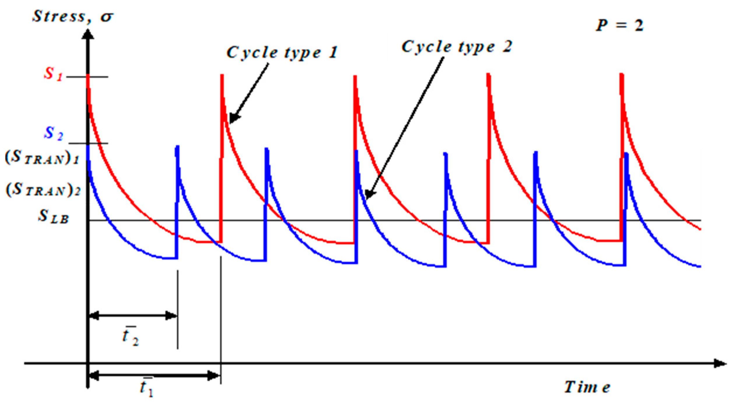
  • Stress cycle types and number of combined cycles;
  • Equivalent strain range corresponding to stress cycle type;
  • Creep strain increments that should be included in the total strain range for each type of stress cycle;
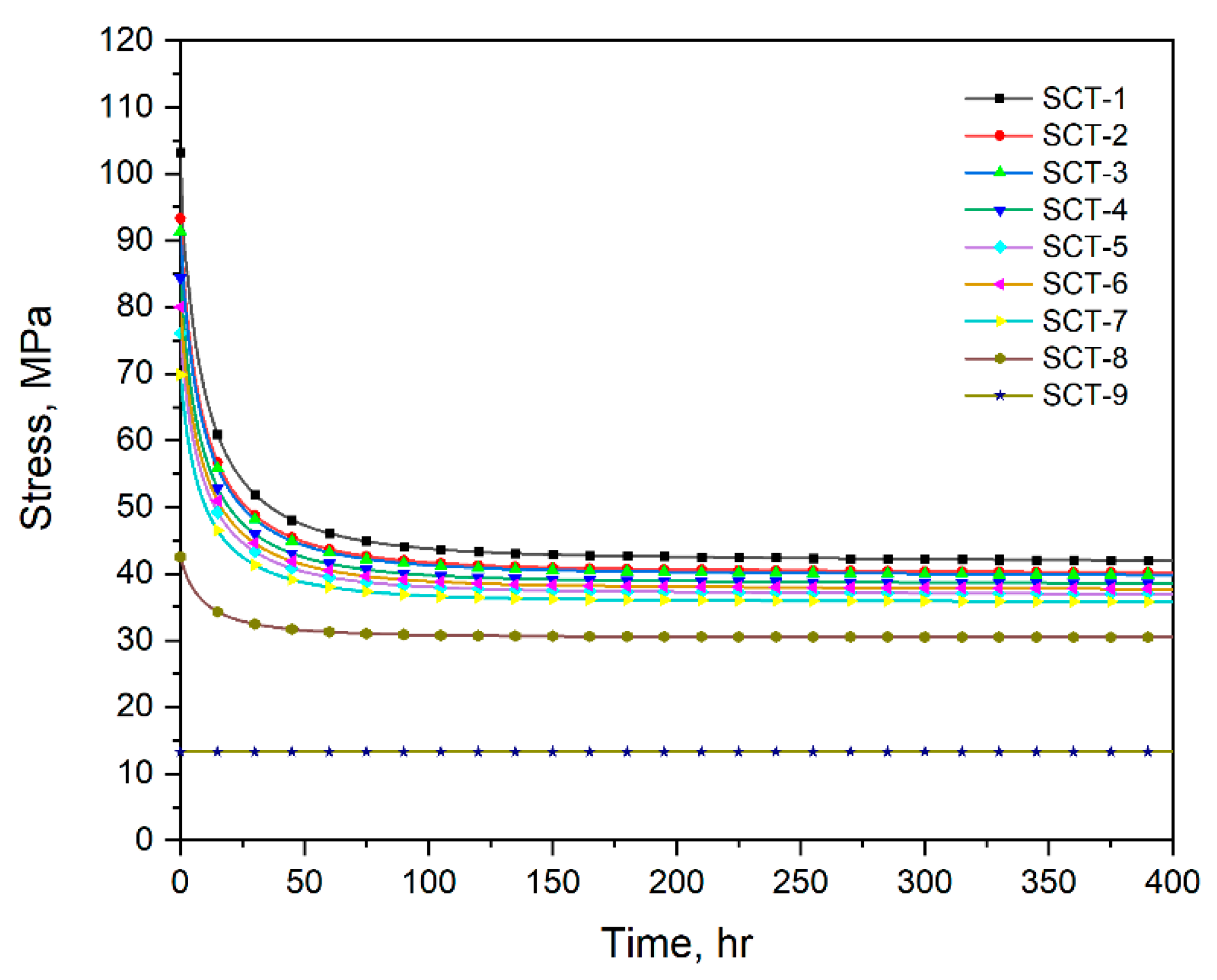
  • Enveloped stress relaxation time history including all stress cycle types;
  • Metal temperature required for each application procedure.
In this study, the main items described above are investigated in detail through the application example of the MSR cladded component with four design operation cycles. In general, the sustained primary load, such as internal pressure, is dominant for creep-damage evaluation, but in the case of MSRs operated at low pressure and high temperature, thermal stress will dominate creep damage when actually based on the procedures required by the elastic approach in ASME-III Division 5. In particular, in the case of cladded components, since the cladding material in contact with the salt coolant affects temperature distribution of a base metal, a detailed temperature distribution analysis including the cladding material is required for the thermal stress analysis of the base metal. In this paper, effects of the clad and the thermal stress are investigated through the detailed creep-fatigue evaluation and the way in which reducing the creep-fatigue damage by the thermal stress reduction are performed and discussed.

2. Review of the Creep-Fatigue Evaluation Procedure of ASME-III Division 5

In this study, the creep-fatigue evaluation procedure for Class A components provided by ASME-III, Division 5, Mandatory Appendix HBB-T [5] is reviewed in detail and practical procedures are presented for application onto actual high-temperature nuclear component design.
For creep-fatigue evaluation, it is required to combine the Levels A, B, and C Service Loadings during the entire design lifetime, including hold time and strain rate effects. For a design to be acceptable, the creep and fatigue damage shall satisfy the following criteria:
j = 1 p ( n N d ) j + k = 1 q ( Δ t T d ) k D
where:
  • D = allowable value for total creep-fatigue damage
  • p = total number of stress cycle types
  • (n)j = number of combining cycles for j-th stress cycle type
  • (Nd)j = allowable number of cycles for j-th stress cycle type
  • q = total number of time intervals for enveloped stress relaxation time history
  • t)k = duration of the k-th time interval
  • (Td)k = allowable time duration for k-th time interval
The creep-fatigue damage value calculated from the above criteria should not exceed the total damage value, D, determined from the creep-fatigue damage envelope curve for each design material shown in Figure 1.

2.1. Procedure of Fatigue Evaluation

When using the elastic analysis method, the high-temperature fatigue damage evaluation procedure is generally similar to the method applied in conventional LWR (light water reactors) [26]. However, since fatigue evaluation at high temperature is based on strain concept, local geometric stress concentrations, multiaxial stress effects, and creep strain increments occurring during stress cycles must be considered when determining the total strain range.
In this study, the high-temperature fatigue evaluation procedure is described with 10 steps as follows:
(Step-1): Determine the number of design cycles and transient operation time for each operation cycle type (OCT) defined as Level A, B, and C Service Loadings during the entire design life.
(Step-2): Perform transient thermal and stress time history analysis by the elastic analysis method for the mechanical and thermal loads of each OCT, and determine the evaluation points (critical location) at which creep-fatigue damage is expected to be significant.
(Step-3): Perform stress linearization for each OCT in the evaluation sections, including the determined evaluation point, and determine the following data from the combination total stress time history curve at the evaluation points:
-
Time points of stress extreme for each OCT;
-
Directional stress components of membrane, bending, and peak stress at stress extremes for each OCT;
-
Maximum metal temperature at stress extremes.
(Step-4): Find the stress cycle types (SCT) and the corresponding combining cycles by the stress extreme pair that result in the maximum stress range from all of the stress extremes [26]. In addition, find the next SCT stress cycle types and the corresponding combining cycles, sequentially, in the same manner.
(Step-5): Calculate the alternating stress (Salt) for each SCT and determine the equivalent strain range ( ϵ m a x ) using the following formula:
ϵ m a x = 2 S a l t E
In the above equation, the elastic modulus E is determined as the value corresponding to the maximum metal temperature during the stress cycle.
(Step-6): Modify the maximum equivalent strain range value with consideration of the effect of local geometric stress concentration.
(Step-7): Calculate the creep strain increment for each SCT.
(Step-8): Determine the total strain range (ϵt) with the modified equivalent strain range ( ϵ m a x ) and creep strain increment (Δϵc) for each SCT as follows:
ϵ t = K v ϵ m o d + K ϵ c
In the above equation, Kv is the multiaxial plasticity and Poisson’s ratio adjustment factor, and K is the local stress concentration factor determined by the following equation:
K = ( P + Q + F ) e f f ( P + Q ) e f f
In the above equation, the effective stress (Von Mises) is calculated as follows:
σ e f f = 1 2 σ x σ y 2 + σ y σ z 2 + σ z σ x 2 + 3 τ x y 2 + τ y z 2 + τ z x 2
(Step-9): Determine the allowable number of cycles corresponding to ϵt for each SCT from the design fatigue curve.
(Step-10): Finally, calculate the accumulated fatigue damage value (Df) from the number of combining cycles (n) and the allowable number of cycles (Nd) corresponding to each SCT as in the following formula:
D f = j = 1 p n N d j
If the evaluation point is a welded part, the allowable number of cycles (Nd)/2 is applied.

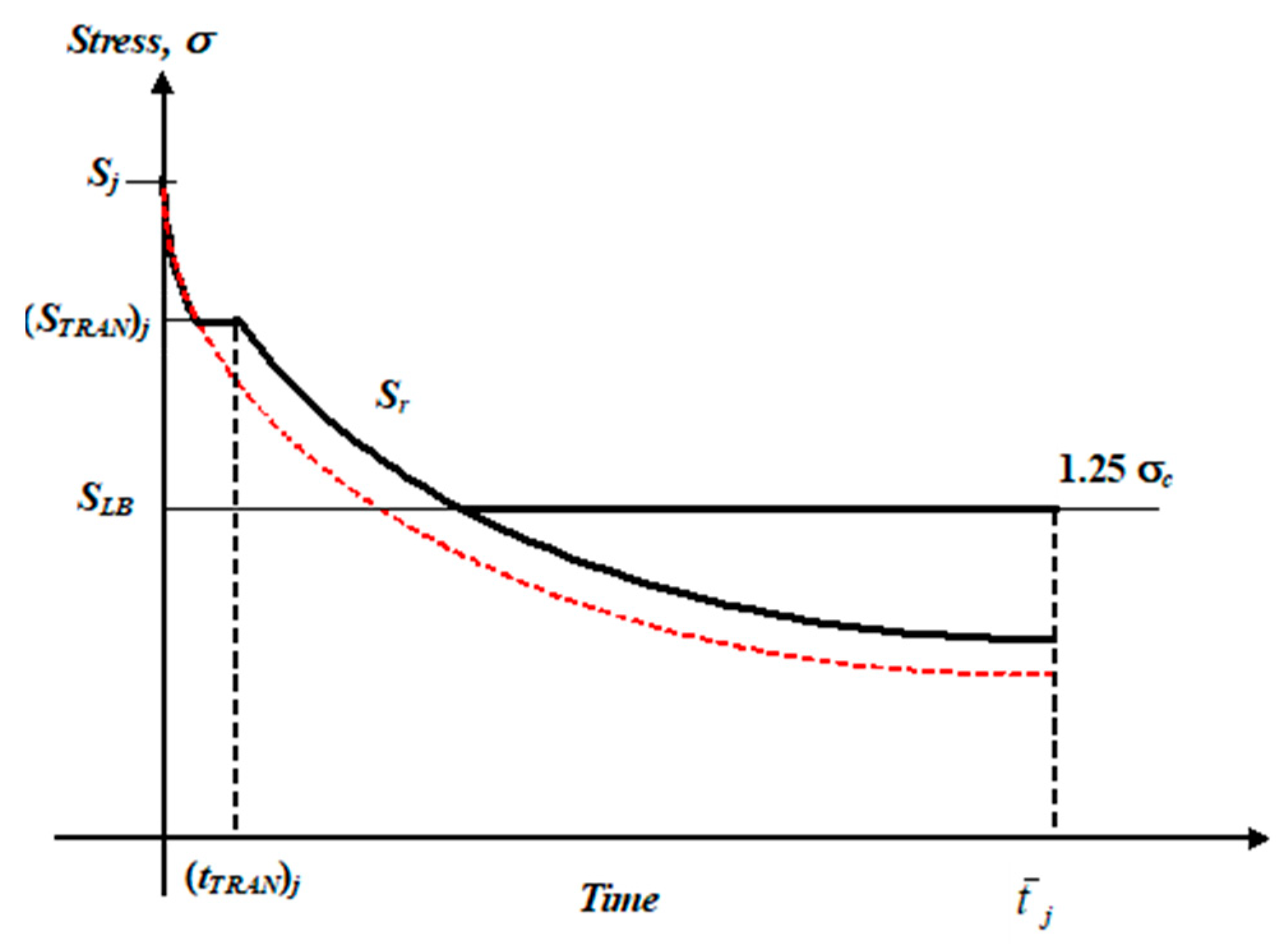
2.2. Procedure of Creep Evaluation

In this study, the creep evaluation procedure is described in 10 steps based on ASME-III Division 5 Nonmandatory Appendix HBB-T, as follows:
(Step-1): Define the total time (tH) experiencing creep temperature during the total design lifetime.
(Step-2): Define the hold temperature (THT) to be equal to the metal temperature at the evaluation point during sustained normal operation.
(Step-3): Define average cycle time t - j for j-th SCT as follows:
t - j = t H / n j
where, nj represents the number of combining cycles of the j-th SCT.
(Step-4): Determine the initial stress level (Sj) corresponding to the total strain range (ϵt) of j-th SCT from the isochronous stress–strain curve at time zero and hold temperature (THT) as shown in the concept of Figure 2.
(Step-5): Determine the stress relaxation time history for j-th SCT corresponding to average cycle time, the initial stress level, the hold temperature from the isochronous stress–strain curve, as shown in blue line arrows of Figure 2.
(Step-6): Modify the j-th stress relaxation time history by reflecting the following transient conditions, as shown in Figure 3 (red line is original), and repeat Step-3 to Step-6 for all SCT:
-
Transient duration (tTRAN)j during average cycle time;
-
Load-controlled stress intensity (STRAN)j;
-
Transient temperature of j-th SCT;
-
Lower bound stress level (SLB).
(Step-7): Superpose the modified stress relaxation time histories repeatedly, extending to the entire design lifetime, as shown in Figure 4, and determine the representative enveloped stress relaxation time history as shown in Figure 5.
(Step-8): Determine the following data to evaluate creep damage from the enveloped stress relaxation time history extended over the entire design lifetime.
-
Time interval, (Δt)k;
-
Stress value at k-th time interval, (S)k.
(Step-9): Determine the allowable duration (Td) corresponding to the stress level (S)k/K′, where K′ is the safety factor, from the expected minimum stress–rupture curves. At this time, the applied temperature uses the hold temperature defined in Step-2.
(Step-10): Finally, calculate the accumulated creep damage value (Dc) from each time interval and corresponding allowable duration by the following equation:
D c = k = 1 q t T d k

3. Exampled Nuclear Component and Operation Cycle Types

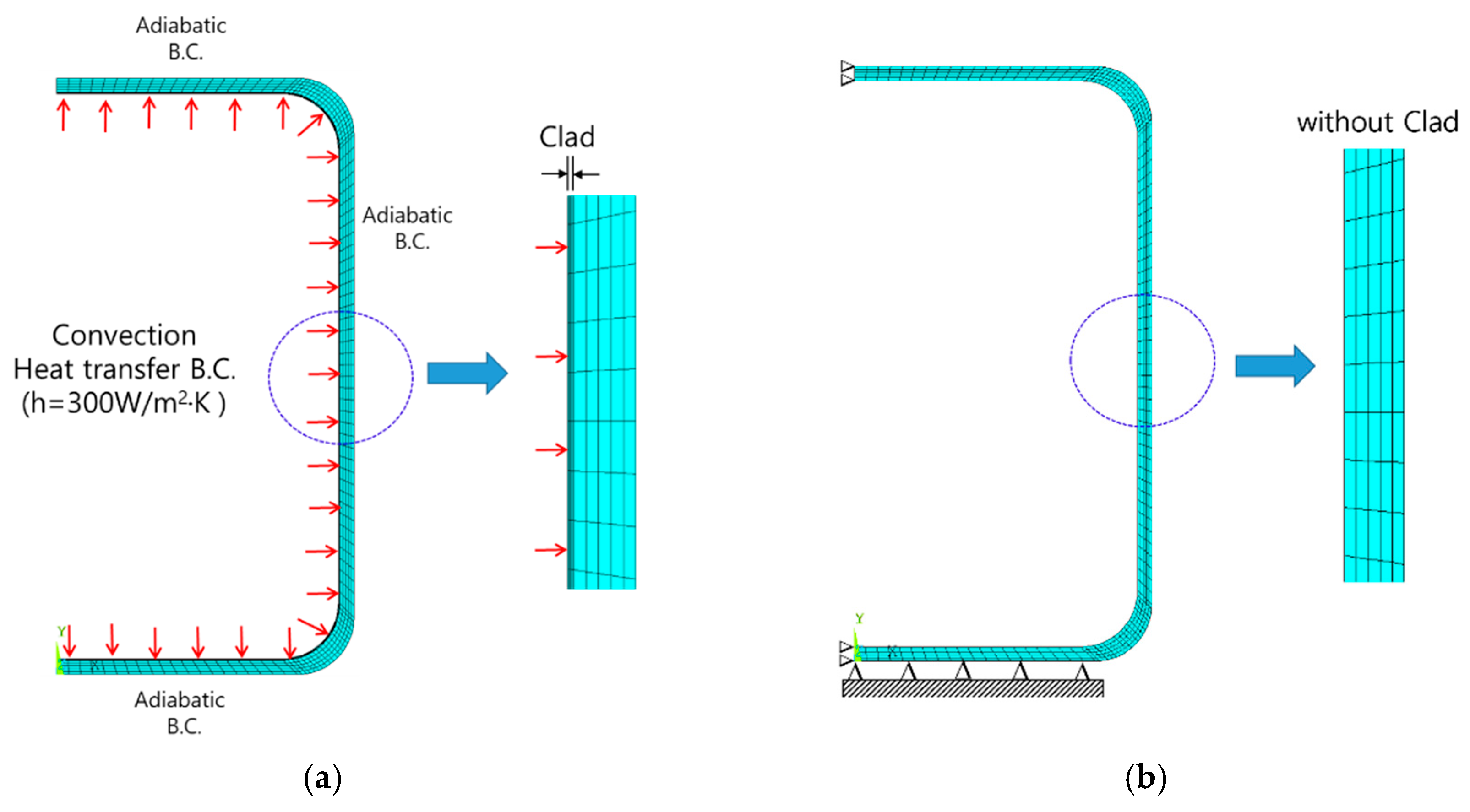
3.1. Geometric Shapes and Cladding

The exampled nuclear component considered in this study is a high-temperature molten salt reactor vessel shaped as a simple cylindrical structure as shown in Figure 6. Both the inner diameter and height of the reactor vessel is 1 m, and the thickness of the base material is 2.5 cm. The inner surface in contact with the corrosive salt coolant is cladded with 0.25 cm thickness, which is 10% of the base material thickness.
The used design base material is Type 316H, which is one of the permitted design materials in ASME-III Division 5 for Class A component design. For the clad materials compatible with the Type 316H material in a molten salt environmental condition, high redox potential materials, such as pure Ni, W, Mo, etc., are recommended [6]. In this study, pure Ni is selected as the clad material due to its cladding manufacturability with Type 316H by the proven weld overlay technique.

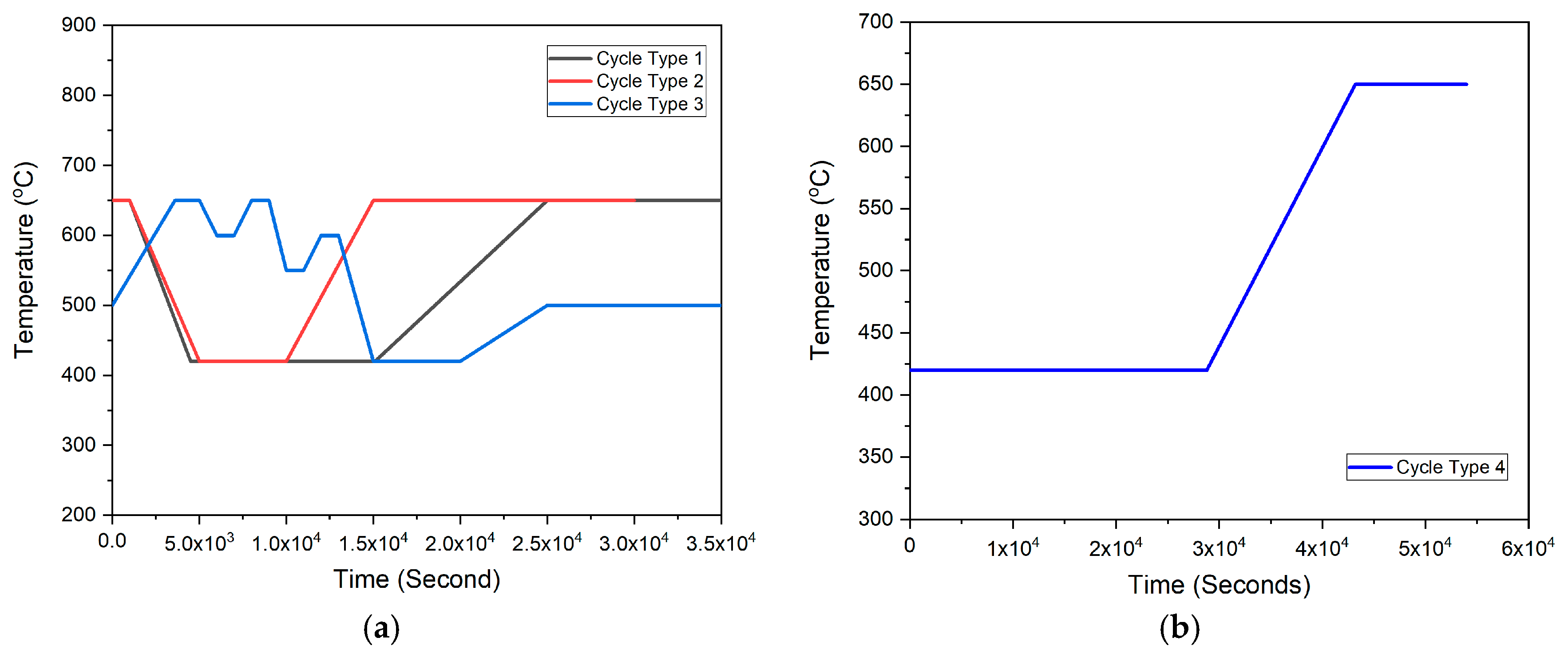
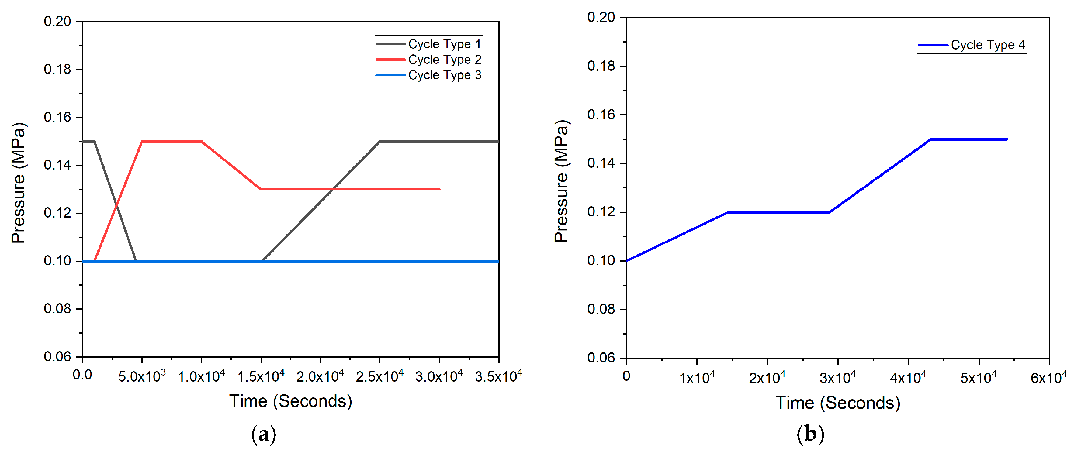
3.2. Operation Cycle Types

As a Step-1 for fatigue evaluation described in Section 2.1 above, the following four operation cycle types are considered in this study as follows:
① Operation cycle type 1 (OCT-1): Normal heat-up and cool-down operation.
② Operation cycle type 2 (OCT-2): Fast heat-up and normal show-down operation.
③ Operation cycle type 3 (OCT-3): Load variation operation.
④ Operation cycle type 4 (OCT-4): High temperature standby and normal heat-up operation.
Figure 7 and Figure 8 show the considered transient temperature and pressure time histories of the operation cycle types described above, respectively. As shown in Figure 7, the maximum coolant temperature during an operation at full power is 650 °C, and the minimum hot standby temperature after cool-down operation is 420 °C. In the case of OCT-3, a severe transient operation in which a continuous temperature fluctuation cycle of 50 °C occurs is regarded.
Table 1 presents the number of design cycles and transient durations for each OCT considered in this study.

4. Finite Element Analysis

4.1. Analysis Modeling and Material Properties

According to Step-2 procedure of fatigue evaluation, finite element thermal and stress analyses are performed for each OCT. For the analyses, the commercial ANSYS [27] finite element analysis program is used in this study. Figure 9 shows the axisymmetric finite element model, including the cladding and the thermal and mechanical boundary conditions. For the finite element analysis, the axisymmetric element of PLANE55 (2-D thermal Solid) is used for thermal analysis, and the axisymmetric PLANE182 (2-D 4 node structural solid) element is used for stress analysis.
As shown in Figure 9b, the clad thickness (0.25 cm) applied in this study is less than 10% of the base metal thickness (2.5 cm), so the existence of the clad can be excluded from the stress analysis according to ASME-III Division 5 HBB-3227.8 requirements. However, since the presence of cladding can affect the temperature distribution of the base material, cladding must be included in the analysis model, as shown in Figure 9a, when analyzing the temperature distribution for thermal stress calculation [6].
For the thermal analysis, as shown in Figure 9a, the outer surface of the reactor vessel is assumed to be an adiabatic boundary, and the inner surface of the cladding in contact with the molten salt is given a convective heat transfer boundary condition of 300 W/m2·K, considering the flow condition of the molten salt. As for the structural boundary conditions for thermal stress and pressure stress analysis, as shown in Figure 9b, an axisymmetric boundary condition is applied to the axial center section of the vessel, and the Y-axis vertical displacement of the vessel bottom is constrained.
Table 2 presents the temperature-dependent material properties of Type 316H provided in ASME-II Part-D [28]. The specific heat values required for the temperature distribution analysis in the table above are not directly provided by the ASME code, but are determined with the density, thermal conductivity (TC) and thermal diffusivity (TD) values provided by the ASME-II from the following relational equation:
Specific Heat [J/(kg·°C)] = Density [kg/m3] · (TC [W/(m·°C)]/TD [m2/s])
The clad material properties of pure Ni used in thermal analysis are as follows:
-
Heat conduction = 60.7 W/(m·°C);
-
Specific heat = 460 J/(kg·°C);
-
Density = 8900 kg/m3.

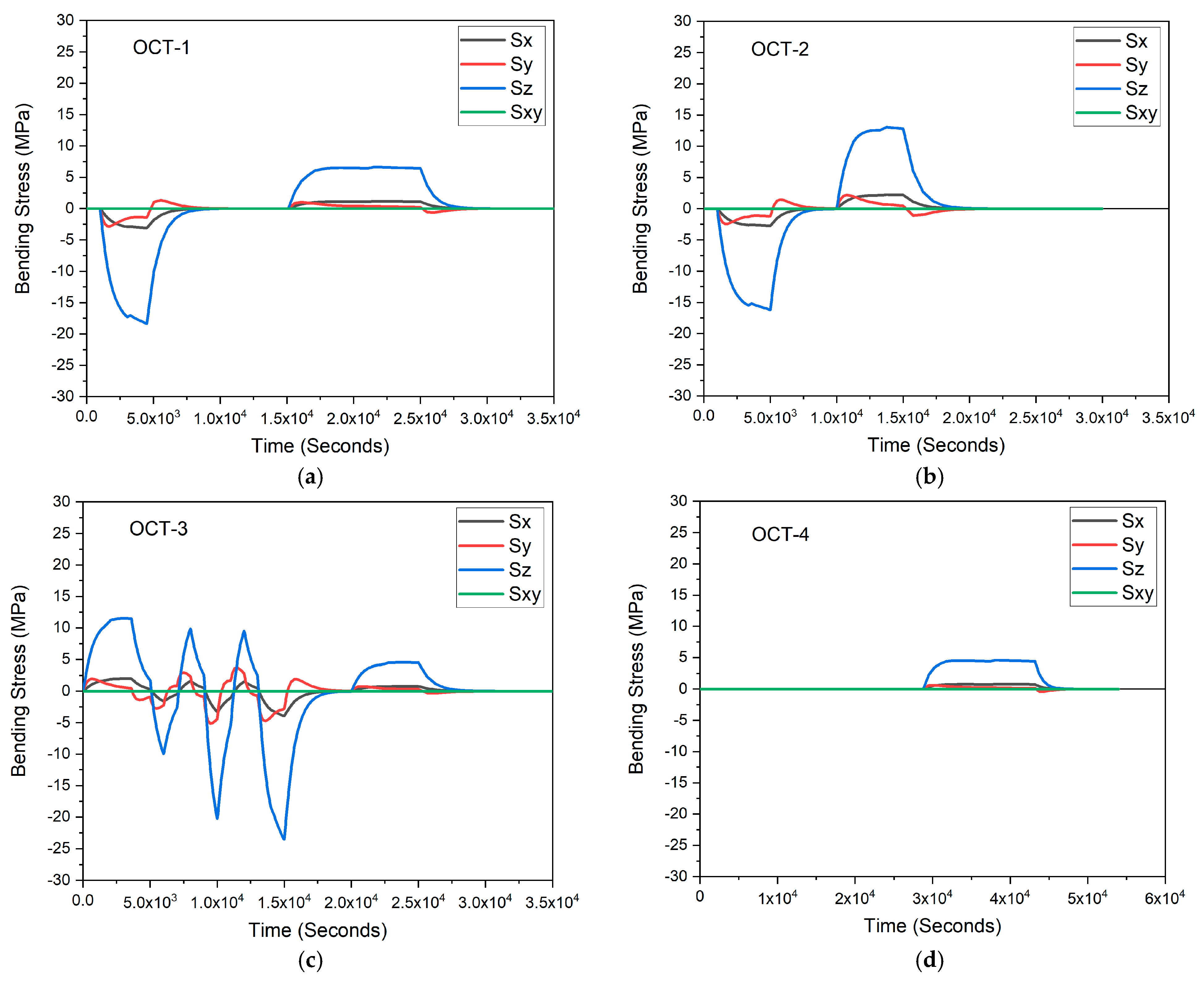
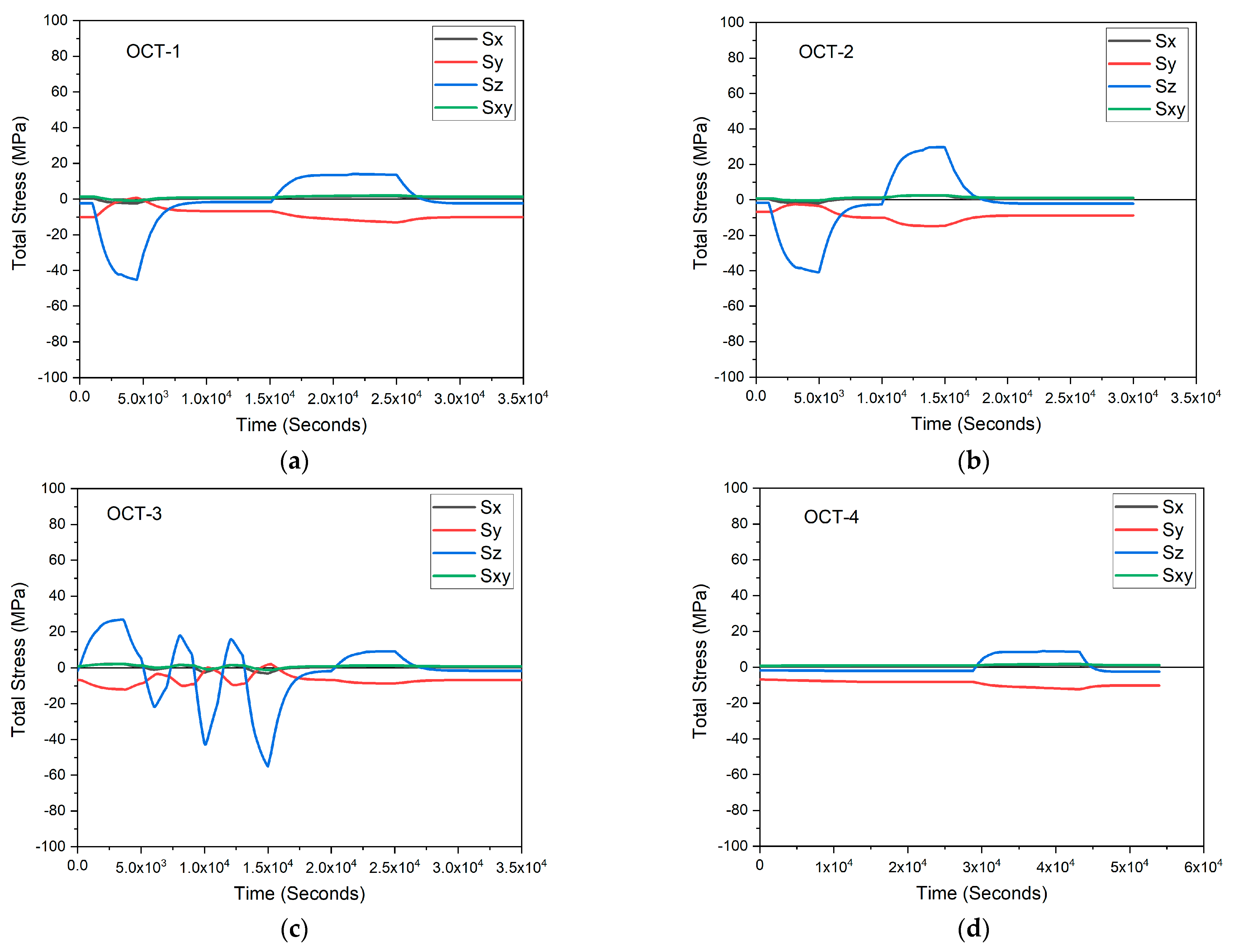
4.2. Stress Analyses

As one of the analysis results, Figure 10a presents the thermal stress intensity distribution by extending the axisymmetric analysis model by 1/4 at the time of 4500 s of OCT-1 when the maximum stress intensity occurs. As shown in the figure, the maximum stress occurs at the outer surface of the fillet region where the cylinder and plate meet. Figure 10b shows the pressure-induced stress intensity distribution for unit pressure load, and it can be found that the maximum primary stress occurs in the fillet region as the same as thermal stress. According to the procedure of fatigue damage evaluation of Step-2, the outer surface of the vessel fillet region is selected as the creep-fatigue evaluation section as shown in Figure 10c.
Through the stress linearization performed on the evaluation section (A-A′) of Figure 10c, including the selected evaluation point, the stress components of membrane, bending, and peak stress time histories at the evaluation point for each OCT are obtained. Figure 11, Figure 12 and Figure 13 present the linearized stress time histories for thermal loads. In addition, Figure 14 presents the total combined stress time histories of thermal and pressure loads.

5. Creep-Fatigue Evaluation

5.1. Determination of Stress Cycle Types and Combining Cycles

For creep-fatigue evaluation, it is necessary to determine the SCTs in which the equivalent strain range becomes the largest one by the combination of all stress extremes obtained for OCTs, and define the combining cycles corresponding to each determined SCT. To do this, if the specific load sequence is not determined, the cycle combination method provided in ASME-III Mandatory Appendix XIII-3520(e) can be used [26]. Similar to an example of this study, this cycle combination method is very practical when the design OCTs and their design number of cycles are specified.
According to Step-3 of the fatigue evaluation procedure, the stress extreme time points, which represent peak and valley stresses, are presented in Table 3.
As shown in the above table, two stress extreme time points are determined for OCT-1, OCT-2, and OCT-4, and six stress extreme time points are determined for OCT-3. In addition, the maximum metal temperature for each stress extreme time point, which is obtained from the thermal analysis, is also presented in Table 3.
In accordance with Step-4 of the fatigue evaluation procedure, the SCTs are determined as a pair of two stress extreme time points (TP1 and TP2) by combining the stress extremes of Table 3. Table 4 presents the determined total 10 SCTs and their number of combined cycles with the cycle combination method of ASME Section III Mandatory Appendix XIII-3520(e). As shown in the table, the SCT-1, which will provide the largest equivalent strain range, with 30 combining cycles, is paired by the time point of the 15,000 s of the OCT-3 and the 14,250 s time point of the OCT-2.

5.2. Fatigue Damage Evaluation

According to Step-5 of the fatigue evaluation procedure, the equivalent strain range (Δϵmax) is required instead of stress range according to the ASME-III Division 5 rules. In the case of using the elastic analysis method, the equivalent strain range for each SCT can be obtained from the alternating stress (Salt) with the elastic modulus corresponding to the maximum metal temperature at the evaluation point by Equation (2). The alternating stress for each SCT can be determined by applying the ASME-III Mandatory Appendix XIII-2400 [26]. Table 5 presents the summary results of the maximum equivalent strain range for each SCT.
As described in Step-6 of the fatigue evaluation procedure, the equivalent strain ranges in Table 5 determined by the elastic analysis method need to be modified with the consideration of the local stress concentration effect. In this example of the application of the study, the equivalent strain range in Table 5 does not require modification because the local stress concentration factors for all SCTs are evaluated as K = 1.
According to Step-7 of the fatigue evaluation procedure, it is required that creep strain increments should be added in determining the total strain range for each SCT. These can be calculated in accordance with ASME Section III Division 5 HBB-T-1432(g). In this process, the concept of effective creep stress σc is introduced as follows:
σ c = Z · S y L
In the above equation, Z represents the effective creep stress parameter and 𝑆𝑦𝐿 represents the yield stress value that corresponds to the lower of the wall-averaged temperatures for the stress extremes defining SCT. The Z value can be determined from the ASME-III Division 5 Figure HBB-T-1332-1 or Figure HBB-T-1332-2 curves. At this time, the required primary stress parameter X and secondary stress parameter Y values are determined as follows [5]:
X = P L + P b K t m a x ÷ S y
Y = Q R m a x ÷ S y
In the above equation, 𝑃L, 𝑃b, and 𝑄R represent the local primary membrane stress, primary bending stress, and secondary stress range, respectively. In determining the above stress parameters X and Y, the secondary stresses with elastic follow-up (i.e., pressure-induced membrane and bending stresses and thermal-induced membrane stresses) are classified as primary stresses [5]. Finally, the creep strain increment is determined by calculating the accumulated creep strain corresponding to the effective creep stress of 1.5σc from the isochronous stress–strain curve for the entire design life of 20 years (175,200 h) defined in this study and dividing it by the number of combining cycles of STC in Table 4. Table 6 summarizes the calculation results of the creep strain increments for each STC. In this study, the conservative ASME Section III Division 5 Figure HBB-T-1332-2 curve is used to determine the creep stress parameter Z.
As described in Step-8 of the fatigue evaluation procedure, the total strain range (ϵt) for each SCT required for fatigue damage evaluation is determined by adding the modified equivalent strain range plus the creep strain increment generated during a single stress cycle. According to the fatigue evaluation step-9, the allowable number of cycles for the total strain range of each STC is determined from the design fatigue curve provided in ASME-III Division 5, Figure HBB-T-1420-1B for Type 316H. Table 7 presents the summary results of the calculated fatigue damage values for each SCT.
Finally, according to the fatigue evaluation of Step-10, the accumulated fatigue damage value is calculated by summing up the fatigue damage for each SCT as follows:
D f = j = 1 p = 9 n N d j = 0.8722 × 10 5
To investigate the effect of the cladding material applied in this study, a fatigue damage evaluation is performed for a case of no-cladded component. Figure 15 shows the comparison results of the total strain ranges with and without cladding material for each SCT. As shown in the figure, we can see that the cladding material affects the total equivalent strain range and slightly increases it. Then, in the case of no-cladded component, the accumulated fatigue damage value decreases to 0.6316 × 10⁻⁵.

5.3. Creep Damage Evaluation

Table 8 presents the summary results of the creep evaluation from Step-1 to Step-4 of the creep evaluation procedure. As shown in Table 8, the total design lifetime (tH) is set to 20 years (175,200 h) and the hold temperature is 650 °C, which is the maximum metal temperature at the evaluation point during steady state operation. The average cycle time ( t - j ) of each SCT required in the creep evaluation procedure of Step-3 is determined by dividing the total design lifetime by the number of combining cycles (nj) of each SCT. In addition, in order to obtain the stress relaxation time history required for creep evaluation, the initial stress level (Sj) corresponding to the total strain range for each SCT defined in the fatigue evaluation is determined from the isochronous stress–strain curve corresponding to the hold temperature.
According to Step-5 of the creep evaluation procedure, Figure 16 presents the stress relaxation time histories obtained from the isochronous stress–strain curve corresponding to the hold temperature of 650 °C during the average cycle time of each SCT, which have the initial stress levels of Table 8.
As Step-6 of the creep evaluation procedures, Table 9 presents the summary results of the lower bound stress level, transient duration time, load-controlled stress intensity level, and the maximum transient temperature required to modify the stress relaxation time histories of Figure 16 with the load-controlled transient effect. In this study, a transient duration time is conservatively defined to be the sum of the transient duration of the OCT corresponding to both two stress extremes defining SCT. According to the ASME code rules, the stress relaxation time histories of all SCT cannot be smaller than the lower bound stress level, SLB, which is the same for all stress cycle types, as the effective creep stress that occurs during normal operation is determined as 1.25 times of effective creep stress.
As Step-7 of the creep evaluation procedure, Figure 17 presents the enveloped stress relaxation time history superposing 10 modified stress relaxation time histories repeatedly extended to the entire design lifetime.
For creep damage calculation according to Step-8, the enveloped stress relaxation time history is equally divided into 1 h time intervals (Δt) and the maximum stresses within each divided time interval are defined as the stepwise stress values. In accordance with Step-9, the stepwise stress levels for each segment of time internal are divided by the safety factor of 0.9 for Type 316H required by ASME-III Division 5 table HBB-T-1411-1 and the allowable time duration (Td) corresponding to each stress level is determined from ASME-III Division 5 Figure HBB-I-14.6, the expected minimum the stress-to-rupture values.
Finally, as Step-10, the accumulated creep damage value (Dc) is obtained by adding all the creep damage values calculated for each time interval of the enveloped stress relaxation time history as follows:
D c = k = 1 q = 175,200 t T d k = 6.093
As shown in the above result, the calculated accumulated creep damage value greatly exceeds the allowable limit of 1.0. To investigate the effect of the cladding on creep damage, the creep calculation for no-cladded component is performed and, as a result, the creep damage value slightly decreases to 5.879. This result is because the pure nickel cladding material used in this study, which has a higher thermal conductivity than the Type 316H base metal, increases the thermal stress of the base metal. This indicates that creep damage evaluation at high temperatures is so sensitive to the level of thermal stress. Figure 18 shows the comparison results of the accumulated creep damage time histories between cladded and no-cladded component.

5.4. Reduction of Creep Damage

As investigated in the above creep damage evaluation, the thermal stress dominates the creep-fatigue evaluation in the application example of this study. Therefore, as one of the methods reducing the thermal stresses in design point of view, reducing the vessel wall thickness is feasible because of a lower pressure operation. In this study, the vessel thickness (TK) is reduced to 1.5 cm with the cladding thickness of 1.5mm, which is 10% of the base metal thickness. Figure 19 presents the comparison results of the total stress time histories. As shown in the figures, the primary stresses due to the internal pressure increase, internal pressure increase to some extent. However, the thermal stresses, especially the hoop stress component (Sz) that dominates the creep-fatigue damage, are greatly reduced.
Figure 20 presents the enveloped stress relaxation time history for the case where the vessel thickness is reduced to 1.5 cm. Compared to Figure 17 above, we can see that the overall stress level is greatly reduced.
When reducing the thermal stress, it is found that the acceptance criteria of creep-fatigue damage envelope required by ASME-III Division 5 are satisfied under the given design conditions of this study, as follows:
-
Fatigue damage (Df) = 0.1568 × 10⁻⁶ < Allowable value = 0.1654: Satisfy;
-
Creep Damage (Dc) = 0.6141 < Allowable value = 1.0: Satisfy.
Figure 21 presents the evaluation results of the creep-fatigue damage envelope acceptance criteria for three conditions performed in this study.

6. Conclusions

In this paper, the study on creep-fatigue evaluation for nuclear cladded components are carried out by the ASME-III Division 5 elastic analysis method. From reviewing the creep-fatigue evaluation procedures and applying them to actual high-temperature molten salt reactor cladded vessel, the following meaningful conclusions are obtained:
-
In this study, a practical creep-fatigue evaluation procedure and its application example are described step by step in detail complying with the ASME-III Division 5 rules.
-
When applying the ASME-III Division 5 rules for creep-fatigue evaluation, it is very important to determine the stress cycle types and their number of combining cycles from the combination of operation cycle types.
-
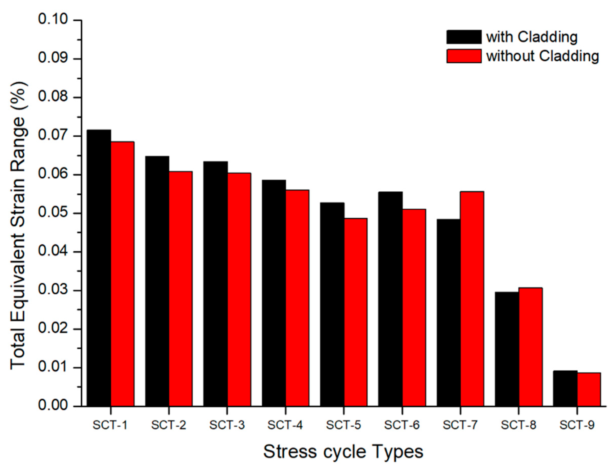
The corrosion resistance cladding material applying to the nuclear components affects the temperature distribution through the vessel wall thickness and can increase creep-fatigue damage value by thermal stress increment. Therefore, the cladding material in the nuclear cladded components needs to be carefully considered for creep-fatigue evaluation.
-
The creep-fatigue evaluations for the nuclear components operating at low pressure and high temperature conditions, such as molten salt reactor, sodium-cooled reactor, and so on, are dominated by the thermal stresses in design by the elastic analysis method of the ASME-III Division 5. Therefore, the structural design minimizing the thermal stresses is important for the structural integrity of high temperature reactors.
-
In conclusion, the described creep-fatigue evaluation procedure and application example in this study can be practically used for the structural integrity evaluation of high-temperature reactors.

Author Contributions

Conceptualization, G.-H.K.; data curation, J.-H.S.; investigation, S.-Y.L. and G.-S.C.; writing—original draft preparation, G.-H.K.; writing—review and editing, J.-H.S., K.-H.S. and G.-S.C.; project administration, G.-H.K. and S.-Y.L.; funding acquisition, G.-H.K. and M.-S.S. All authors have read and agreed to the published version of the manuscript.

Funding

This study was funded by the Korea Electric Association (KEA): Korea Electric Power Industry Code (KEPIC) Department (No. 22-002).

Data Availability Statement

Not applicable.

Conflicts of Interest

The authors declare no conflict of interest.

References

  1. Serp, J.; Allibert, M.; Benes, O.; Delpech, S.; Feynberg, O.; Ghetta, V.; Heuer, D.; Holcomb, D.; Ignatiev, V.; Kloosterman, J.L.; et al. The molten salt reactor (MSR) in generation IV: Overview and perspectives. Prog. Nucl. Energy 2014, 77, 308–319. [Google Scholar] [CrossRef]
  2. ORNL/SPR-2019/1089; Technical Gap Assessment for Materials and Component Integrity Issues for Molten Salt Reactors. Oak Ridge National Laboratory: Oak Ridge, TN, USA, 2019.
  3. ANL/EXT-18-45171; Status of Metallic Structural Materials for Molten Salt Reactors; Revision 0. Argonne National Laboratory: Lemont, IL, USA, May 2018.
  4. Barua, B.; Messner, M.C.; Jetter, R.I.; Sham, T.-L. Selection Criteria for Clad Materials to Use with a 316H Base Material for High Temperature Nuclear Reactor Cladded Components. In Proceedings of the ASME 2020 Pressure Vessels & Piping Division Conference PVP2020, Minneapolis, MN, USA, 19–24 July 2020. PVP2020-21493. [Google Scholar]
  5. ASME. ASME Boiler and Pressure Vessel Code Section III; Division 5; ASME: New York, NY, USA, 2021. [Google Scholar]
  6. ANL-21/11; Design Rules for 316H Nuclear Components Cladded with Nickel or Tungsten. Argonne National Laboratory: Lemont, IL, USA, March 2021.
  7. Barua, B.; Jetter, R.I.; Messner, M.C.; Sham, T.-L. Simplified Criteria with Reduced Testing Effort for Selecting Clad Materials for High Temperature Reactor Structural Components. In Proceedings of the ASME 2021, Pressure Vessels & Piping Division Conference, PVP2021, Virtual, 12–16 July 2021; p. 2021. [Google Scholar]
  8. Messner, M.C.; Phan, V.-T.; Jetter, R.I.; Sham, T.-L. The Mechanical Interaction of Clad and Base Metal for Molten Salt Reactor Structural Components. In Proceedings of the ASME 2018 Pressure Vessels and Piping Conference PVP2018, Prague, Czech Republic, 15–20 July 2018. [Google Scholar]
  9. ANL-ART-134; Finite Element Analysis of Compliant Cladding and Base Metal Systems. Argonne National Laboratory: Lemont, IL, USA, July 2018.
  10. Mariappan, K.; Nagesha, A. Creep-fatigue interaction behavior of simulated microstructures and the actual weldment of P91 steel. Mater. Sci. Eng. A 2023, 866, 144695. [Google Scholar] [CrossRef]
  11. Shanyavskiy, A.; Shlyannikov, V.; Soldatenkov, A.; Rubtsov, V. Micromechanics of fatigue, creep-fatigue interaction and thermomechanical crack growth of XH73M nickel alloy. Struct. Integr. Procedia 2023, 43, 215–220. [Google Scholar] [CrossRef]
  12. Alsmadi, Z.T.; Abouelella, H.; Alomari, A.S.; Murty, K.L. Stress-Controlled Creep–Fatigue of an Advanced Austenitic Stainless Steel at Elevated Temperatures. Materials 2022, 15, 3984. [Google Scholar] [CrossRef] [PubMed]
  13. Liu, N.; Dai, H.; Xu, L.; Tang, Z.; Li, C.; Zhang, J.; Lin, J. Modeling and effect analysis on crack growth behavior of Hastelloy X under high temperature creep-fatigue interaction. Int. J. Mech. Sci. 2021, 195, 106219. [Google Scholar] [CrossRef]
  14. Jadon, J.K.S.; Singh, R.; Mahato, J.K. Creep-fatigue interaction behavior of high temperature alloys: A review. Mater. Today: Proc. 2022, 62, 5351–5357. [Google Scholar]
  15. Rao, G.V.S.N.; Kumar, P.A.; Kannan, R.; Nagesha, A. Influence of Temperature and Strain Amplitude on Low Cycle Fatigue and Creep–Fatigue Interaction Behaviour of Alloy 617 M. Trans. Indian Natl. Acad. Eng. 2022, 7, 509–517. [Google Scholar]
  16. Alsmadi, Z.Y.; Murty, K.L. High-temperature effects on creep-fatigue interaction of the Alloy 709 austenitic stainless steel. Int. J. Fatigue 2021, 143, 105987. [Google Scholar]
  17. Takahashi, Y. Creep-fatigue interaction: Its mechanism and predictability. In Proceedings of the Asian Pacific Conference for Materials and Mechanics 2009, Yokohama, Japan, 13–16 November 2009. [Google Scholar]
  18. Barbera, D.; Chen, H.; Liu, Y. On Creep Fatigue Interaction of Components at Elevated Temperature. J. Press. Vessel. Technol. 2016, 138, 041403. [Google Scholar] [CrossRef] [Green Version]
  19. Yokobori, T.; Yokobori, A.T., Jr. High temperature creep, fatigue and creep-fatigue interaction in engineering materials. Int. J. Press. Vessel. Pip. 2001, 78, 903–908. [Google Scholar] [CrossRef]
  20. AFCEN. RCC-MRx: Design and Construction Rules for Mechanical Components in High-Temperature Structures, Experimental Reactors, Fusion Reactor; AFCEN: Lyon, France, 2015. [Google Scholar]
  21. British Energy Generation Ltd. Assessment Procedure for the High Temperature Response of Structures (R5); British Energy Generation Ltd.: Gloucester, UK, 2003. [Google Scholar]
  22. PNC. Elevated Temperature Structural Design Guide for Class 1 Components of Prototype Fast Breeder Reactor; PNC N241-84-08; PNC: Yokohama, Japan, 1984. [Google Scholar]
  23. Koo, G.H.; Lee, J.H. Development of an ASME-NH program for nuclear component design at elevated temperatures. Int. J. Press. Vessel. Pip. 2008, 85, 385–393. [Google Scholar] [CrossRef]
  24. Koo, G.H.; Lee, J.H. Elevated Temperature Design of KALIMER Reactor Internals Accounting for Creep and Stress-Rupture Effects. J. Korean Nucl. Soc. 2000, 32, 566–594. [Google Scholar]
  25. Koo, G.H.; Yoo, B. Evaluation of Creep-Fatigue Damage of KALIMER Reactor Internals Using the Elastic Analysis Method in RCC-MR. J. Korean Nucl. Soc. 2001, 33, 566–584. [Google Scholar]
  26. ASME. ASME Boiler and Pressure Vessel Code Section III, Mandatory Appendix XIII; ASME: New York, NY, USA, 2021. [Google Scholar]
  27. ANSYS Mechanical APDL Release 15.0; ANSYS, Inc.: Canonsburg, PA, USA, 2013.
  28. ASME. ASME Boiler and Pressure Vessel Code Section II, Part D; ASME: New York, NY, USA, 2021. [Google Scholar]
Figure 1. Creep-fatigue damage envelope [5].
Energies 16 02898 g001
Figure 2. Schematic concept determining initial stress level and stress relaxation time history.
Energies 16 02898 g002
Figure 3. Schematic concept considering transient conditions for modifying stress relaxation time history.
Energies 16 02898 g003
Figure 4. Schematic concept superposing and extending the stress relaxation time histories.
Energies 16 02898 g004
Figure 5. Schematic concept enveloping the extended stress relaxation time histories.
Energies 16 02898 g005
Figure 6. Dimensional configurations of reactor vessel and cladding.
Energies 16 02898 g006
Figure 7. Used operation cycle types for temperature: (a) OCT-1~OCT-3; (b) OCT-4.
Energies 16 02898 g007
Figure 8. Used operation cycle types for pressure: (a) OCT-1~OCT-3; (b) OCT-4.
Energies 16 02898 g008
Figure 9. Finite element analysis model and boundary conditions: (a) for thermal; (b) for stress.
Energies 16 02898 g009
Figure 10. Results of stress analyses and selected evaluation section: (a) thermal stress intensity distribution (at time 4500 s of OCT-1); (b) unit pressure-induced stress intensity distribution; (c) selected creep-fatigue evaluation section.
Energies 16 02898 g010
Figure 11. Thermal-induced membrane stresses: (a) OCT-1; (b) OCT-2; (c) OCT-3; (d) OCT-4.
Energies 16 02898 g011
Figure 12. Thermal-induced bending stresses: (a) OCT-1; (b) OCT-2; (c) OCT-3; (d) OCT-4.
Energies 16 02898 g012
Figure 13. Thermal-induced peak stresses: (a) OCT-1; (b) OCT-2; (c) OCT-3; (d) OCT-4.
Energies 16 02898 g013
Figure 14. Total combined stresses of thermal and pressure: (a) OCT-1; (b) OCT-2; (c) OCT-3; (d) OCT-4.
Energies 16 02898 g014
Figure 15. Comparison of total equivalent strain ranges for cladded and no-cladded component.
Energies 16 02898 g015
Figure 16. Determined stress relaxation time histories for each SCT.
Energies 16 02898 g016
Figure 17. Determined enveloped stress relaxation time history: (a) during entire lifetime; (b) zoomed to 20,000 h.
Energies 16 02898 g017
Figure 18. Comparison of accumulated creep damage time histories between cladded and no-cladded component: (a) during entire lifetime; (b) zoomed to 30 h.
Energies 16 02898 g018
Figure 19. Comparison of total stresses for OST-1: (a) for pressure (TK = 2.5 cm); (b) for pressure (TK = 1.5 cm); (c) for thermal (TK = 2.5 cm); (d) for thermal (TK = 1.5 cm).
Energies 16 02898 g019
Figure 20. Determined enveloped stress relaxation time history for TH = 1.5 cm: (a) during entire lifetime; (b) zoomed to 45,000 h.
Energies 16 02898 g020
Figure 21. Evaluation results of creep-fatigue envelope criteria.
Energies 16 02898 g021
Table 1. Design number of cycles and transient time durations.
OSTsDesign No. of CyclesTransient Duration (h)
OCT-12007.0
OCT-2504.2
OCT-3307.0
OCT-43012.0
Table 2. Used material properties of Type 316H.
PropertiesTemperature (°C)
20100200300400450500550600650
Heat conduction
(W/m2·°C)
14.115.416.818.319.720.521.221.922.623.2
Specific heat
[J/(kg·°C)]
491.9511.4525.7540.0552.5561.1566.5570.6574.4576.7
Density
(kg/m3)
8030803080308030803080308030803080308030
Thermal expansion
(10−6/°C)
15.317.018.419.119.519.820.220.621.121.6
Elastic modulus
(GPa)
209189183176169165160156151146
Poisson’s ratio0.310.310.310.310.310.310.310.310.310.31
Table 3. Defined stress extreme time points and metal temperature.
OCT No.Stress Extreme Time Points (s)
(Metal Temperature, °C)
TP1TP2TP3TP4TP5TP6
OCT-14500
(468)
25,000
(633)
OCT-24870
(469)
14,250
(582)
OCT-33600
(620)
6050
(625)
8100
(627)
10,100
(597)
12,100
(579)
15,000
(478)
OCT-443,200
(638)
54,000
(650)
Table 4. Determined Stress Cycle Types and Their Number of Combined cycles.
SCT No.TP1TP2Combined CyclesMetal Temp
(°C)
OCT No.Time (s)OCT No.Time (s)
SCT-1315,000214,25030582
SCT-214500214,50020582
SCT-3145003360030620
SCT-4145003810030627
SCT-514500125,000120633
SCT-6310,100125,00030633
SCT-724870125,00050633
SCT-8312,1003605030625
SCT-9443,200454,00030650
Table 5. Calculated maximum equivalent strain ranges.
SCT No.Salt (MPa)E (GPa)Δϵmax (%)
SCT-151.06152.800.0668
SCT-245.56152.800.0596
SCT-342.69149.020.0573
SCT-437.03148.270.0499
SCT-536.62147.700.0496
SCT-634.72147.700.0470
SCT-732.28147.700.0437
SCT-821.45148.530.0289
SCT-96.57146.000.0090
Table 6. Calculated creep strain increments.
SCT No.XYZ1.25σc (MPa) Δ ϵ c (%)
SCT-10.38550.28890.442563.450.4757 × 10−2
SCT-20.32210.25560.369352.960.5082 × 10−2
SCT-30.32870.24880.375052.690.6052 × 10−2
SCT-40.33050.21980.371451.910.8454 × 10−2
SCT-50.33190.20790.370651.590.3141 × 10−2
SCT-60.30600.19890.342047.610.8457 × 10−2
SCT-70.30250.18950.336746.870.4714 × 10−2
SCT-80.15390.13640.174524.430.6009 × 10−3
SCT-90.06110.03860.06639.120.2168 × 10−3
Table 7. Summary of fatigue evaluation for each SCT.
jSCT No. ϵ t nj(Nd)j(Df)j = (n/Nd)j
1SCT-10.0716300.8971 × 1070.3344 × 10−5
2SCT-20.0647200.1892 × 1080.1057 × 10−5
3SCT-30.0634300.2214 × 1080.1355 × 10−5
4SCT-40.0585300.3995 × 1080.7508 × 10−6
5SCT-50.05271200.8614 × 1080.1393 × 10−5
6SCT-60.0555300.5911 × 1080.5076 × 10−6
7SCT-70.0484500.1615 × 1090.3096 × 10−6
8SCT-80.0295300.6336 × 10100.4735 × 10−8
9SCT-90.0092300.3465 × 10140.8658 × 10−12
Table 8. Summary of determined initial stress levels.
SCT No.tH (h)THT (°C)nj ( t - j ) (h) Sj (MPa)
SCT-1175,200650305840103.20
SCT-2175,20065020776093.32
SCT-3175,20065030584091.36
SCT-4175,200650305.84084.35
SCT-5175,200650120146076.03
SCT-6175,20065030584080.00
SCT-7175,20065050350469.84
SCT-8175,20065030584042.52
SCT-9175,20065030584013.29
Table 9. Summary of parameter values for modifying stress relaxation time histories.
SCT No.SLB (MPa)(TTRAN)j (h)(TTRAN)j (°C)(Pm + Pb)TRAN (MPa)
SCT-163.4511.26508.57
SCT-263.4511.26508.57
SCT-363.4514.06508.57
SCT-463.4514.06508.57
SCT-563.4514.06508.57
SCT-663.4514.06508.57
SCT-763.4511.265012.72
SCT-863.4514.06508.57
SCT-963.4524.065012.86
Disclaimer/Publisher’s Note: The statements, opinions and data contained in all publications are solely those of the individual author(s) and contributor(s) and not of MDPI and/or the editor(s). MDPI and/or the editor(s) disclaim responsibility for any injury to people or property resulting from any ideas, methods, instructions or products referred to in the content.

