Article

Performance Analysis of Overcurrent Protection under Corrupted Sampled Value Frames: A Hardware-in-the-Loop Approach

by
Ângelo Felipe Sartori
1,
Adriano Peres de Morais
1,
Ulisses Chemin Netto
2,
Diomar Adonis Copetti Lima
1,
Daniel Pinheiro Bernardon
1,* and
Wagner Seizo Hokama
3
1
Headquarters Campus, Federal University of Santa Maria, Santa Maria 97105-900, RS, Brazil
2
Headquarters Campus, Federal Technological University of Paraná, Curitiba 80230-901, PR, Brazil
3
CPFL Energia, Campinas 13088-900, SP, Brazil
*
Author to whom correspondence should be addressed.
Energies 2023, 16(8), 3386; https://doi.org/10.3390/en16083386
Submission received: 11 February 2023 / Revised: 19 March 2023 / Accepted: 27 March 2023 / Published: 12 April 2023

Abstract

:
The IEC 61850 standard aims at digitization substations and provides interoperability between various Intelligent Electronic Device vendors. The digitization process is accompanied by several challenges related to data transmission on the ethernet network and the protection behavior under these conditions. Among the challenges, we can mention packet loss, delay, and duplicate frame, which occurs when the merging units (publisher) transmit the sampled values and, for some reason, these packets do not reach the subscriber or are duplicated. Nowadays, most Intelligent Electronic Device manufacturers block the protection function when some sampled value packets are corrupted. The effects of blocking protection when packet loss occurs under normal operating conditions do not cause significant problems. However, when a fault occurs, the corrupted packets can cause a delay in fault clearance, causing even more damage to the grid. The purpose of this article is to present the effects of corrupted sampled values on the performance of overcurrent protection. All the evaluations were performed in real time using the hardware-in-loop simulation approach with a commercial Intelligent Electronic Device. The OP5700 hardware platform from OPAL-RT, with the library “IEC 61850 Data Integrity Manipulation”, was used. The results show that corrupted sampled value frames affect the functioning of the protections.

1. Introduction

A fully digital Substation Automation System (SAS) through an ethernet network provides an infrastructure for high-speed data transfer regarding digital and analog quantities [1]. A globally appropriate solution involves the direct implementation of IEC 61850 standards. Building an SAS upon IEC 61850 brings various advantages, such as interoperability and price reduction in implementation [2,3] and monitoring several variables [4], that, in traditional SAS, would not be possible or would be expensive and complex. The IEC 61850 Standard—the communication networks and systems for power utility automation—established a first edition in 2003/04; it is in the second edition, published in 2013. The IEC 61850 standard establishes three main communication protocols: Manufacturing Message Specification (MMS), Generic Object-Oriented Substation Event (GOOSE), and Sampled Values (SVs).
The MMS protocol has applicability for communication with higher-level systems such as the SCADA system. The GOOSE protocol, as defined in part 8-1 of the standard, has applicability in exchanging messages between Intelligent Electronic Device (IEDs) and IEDs and Merging Units (MU) [5] to perform interlocking, exchange of logic states [6], and tripping circuit breakers [7]. The GOOSE message has a retransmission mechanism of the data to improve reliability. Hence, this type of message has a low probability of loss for data packets.
The SV protocol, as defined in part 9–2 of the standard, is mainly used to transmit current and voltage values from the MU to IEDs. The SV protocol is a layer-two multicast message, transmitted cyclically in periods of 208 microseconds at 60 Hz, implying a maximum of 256 samples per cycle for measurement application and 80 samples per cycle for protection purposes [8]. Hence, the SV message carries short periodic sampled values of voltage and current, resulting in large network traffic.
Furthermore, it aims to standardize the compression of current and voltage data and other necessary information for communication. One of its characteristics is the non-retransmission of values, meaning that if an event results in the loss of a sample, the MU will not resend the values. Figure 1. shows the acquisition of an SV message using Wireshark software.
Some information in the packet sent via SV is essential to highlight: svID is the name of the MU and smpCnt is data ranging from 0 to 4799 when the system’s frequency is 60 Hz. This value is intended to allow for a reference for the IED to know the position of the values of the sine signal. The term smpSynch represents communication with the timing clock. It can assume three values: no time synchronization (0), local area clock (1), and global area clock (2). Finally, the values of phase and neutral currents, phase voltage and neutral, and the bit quality values sent by MU indicate the quality of the information sent. In cases where the bit quality is doubtful, the IED can refuse the SV frame.
According to [9], the use of IEC 61850 significantly impacts the operation of substations, as it increases the possibilities for protection solutions. Applications such as bus protection are easier to implement, especially when the bus configuration changes. In addition to reducing implementation costs compared to wired analog protection, a significant benefit is the reduction in CT saturation due to the short distance between the CT and the MU and improved maintenance safety.
Hardware in-the-loop (HIL) simulation for real-time IEC 61850 testing is a reliable solution for new SAS projects [10]. However, few works about IEC 61850 hardware in the loop are available. There are some papers with the GOOSE approach, as presented in [10], where round-trip delay is evaluated using real-time simulation. Westman et al. [11] uses a digital protection relay to provide inputs and outputs to simulated controllers through GOOSE messages. Interoperability experiments regarding multiple IED vendors are reported in [1]. Some practical examinations were performed on IEDs checking GOOSE message exchange and the functionality of the manufacturer’s software [12]. In [13], a hardware–software co-simulation environment can model the relationship between the cyber and physical parts to provide a protection scheme for the microgrid. In [14], a comparison is made between traditional protections by process bus and hybrid.
The literature presents few papers about corrupted data or manipulations of data in the SV package, mainly because it is still a new subject. Problems related to the study of this paper may occur due to device issues (MU or switch) or cyberattacks. In [15], a study was conducted on attacks on facilities communicating with IEC 61850. According to the author, these attacks can exploit vulnerabilities in communication standards, and malware has already been found in some real systems.
In [16], several tests were carried out by invading the network that carries the SV protocol and injecting parallel SV packets into the original SVs. In one of the tests, the smpCnt value is monitored, and a false value is injected at a certain point. In [16], the level showed that, on average, 20% of the packets transmitted by the MU are lost during an attack. In [17], the study flowed into another path, showing the impacts that packet loss can cause in the SAS operation. In [18], a methodology was proposed to detect false SV packets, as well as to predict lost SV packets. While [17] presents a solution for SV packet loss and delay, the methodology is based on data interpolation.
Thus, this paper aims to present the behavior of overcurrent protection (ANSI 50 and 51) under corrupted SV packets considering different scenarios. All tests were carried out using a real-time simulator and a commercial IED.

2. Problem Description

Unlike GOOSE messages, the SV message is not transmitted repeatedly; hence, to avoid an unwanted trip or trip with extra delays of the protection system, more attention should be paid to the SV packet [8]. There are different possible problems in the SV frames, such as loss of packets on the network, delay, transmission doubling, etc. For instance, if a time-inverse overcurrent protection, during a short circuit, subscribes an SV message with delay or is duplicated, the tripping time will not be as expected.

2.1. Sampled Value Manipulation

The real-time hardware-in-the-loop approach used in this paper includes power system modeling, commercial IEDs, ethernet switches, and other hardware components, allowing the user to analyze power system behavior in closet realistic conditions [19].
The OPAL-RT, as part of the laboratory testbed, allows for designing, testing, and optimizing systems applied to electrical networks, electronic devices, and others [20]. The real-time simulator has a library called “IEC 61850 Data Integrity Manipulation”, which allows for various manipulations of the sampled value messages. There are six types of transmitted SV frame manipulations, according to Table 1. The manipulations #1 to #6 are inherent in the OPAL-RT library, while the authors developed #7. In this paper, the types 1 to 5 and 7 were applied, and each one of them will be described.

2.1.1. Packet Loss

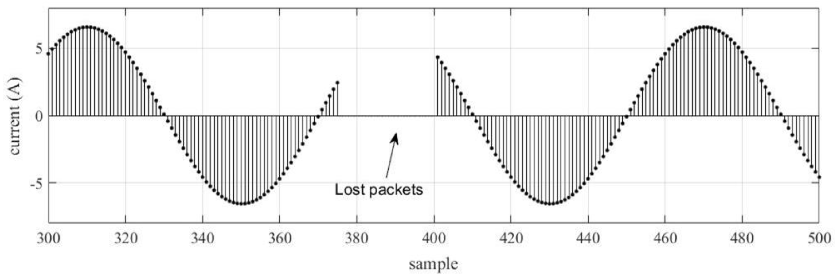
Packet loss occurs when some SV frames in a power cycle do not reach the subscriber. It is characterized by the absence of information in the waveform; Figure 2. shows an example of a sinusoidal signal with 25 packets lost.

2.1.2. Duplicate Packets

Packet duplication consists of the repeated sending of frames by MU. Repetition can occur in two ways: repeating multiple frames of only one sample, shown in Figure 3a, or with the duplication of packets in sequence, when two original frames are duplicated according to what is shown in Figure 3b. The examples cited had the duplication of three frames (a) and (b) three duplicate frames with two duplicates in sequence.

2.1.3. Delayed Packets

A delayed SV frame is characterized when a sample’s basal time is stochastically incremented. Figure 4 displays a delay of 625 us for some SV frames; depending on the time increment, a delayed SV frame could evolve into an SV lost frame.

2.1.4. SmpCnt Manipulation

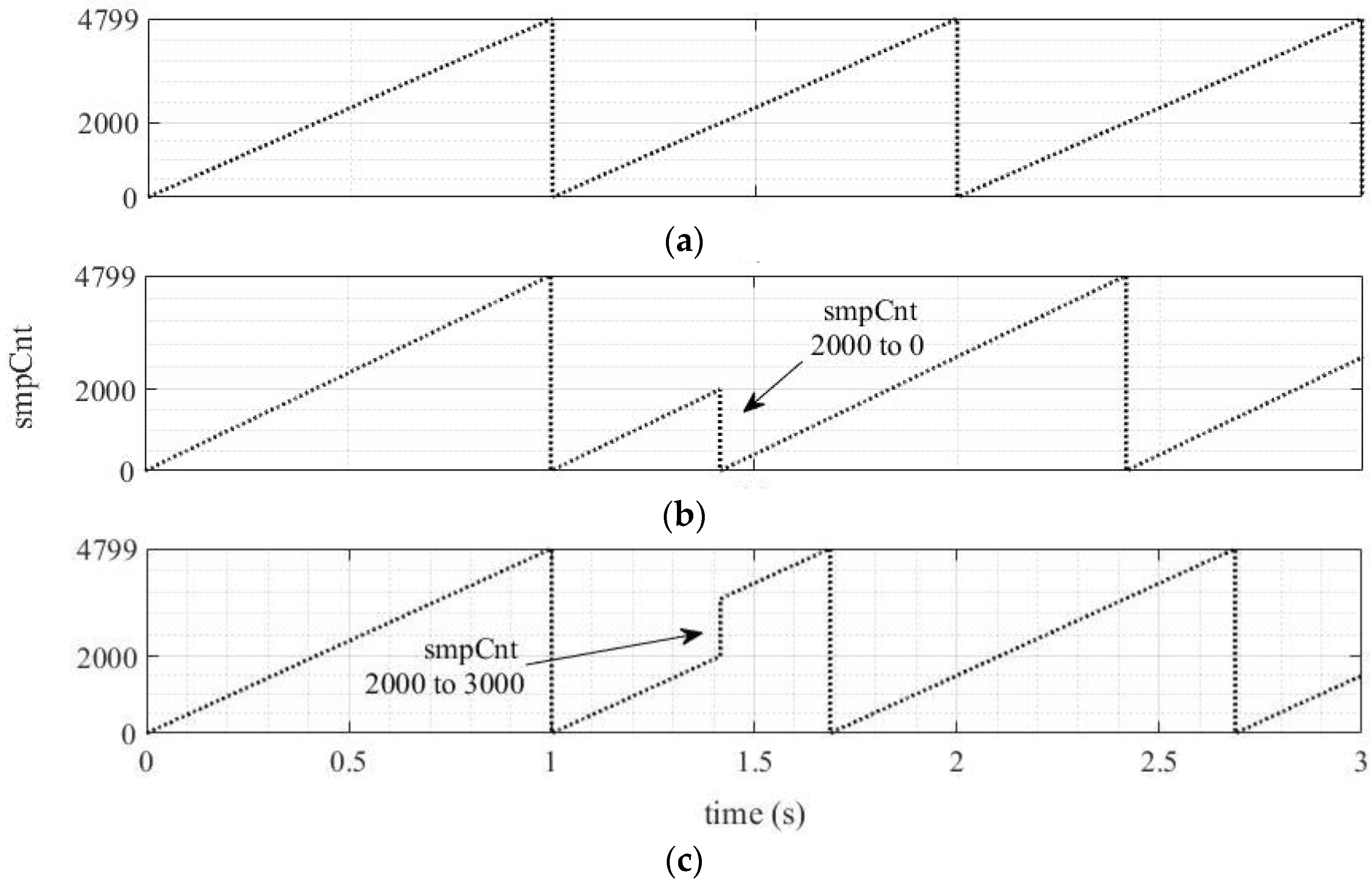
Under the normal operating condition, the values of smpCnt range from 0 to 4799, considering a fundamental frequency of 60 Hz and 80 samples per power cycle, as shown in Figure 5a. If some abnormality occurs in the MU, the smpCnt counter may receive an out-of-order value, i.e., in Figure 5b, where the value abruptly changes from 2000 to 0. Like the previous case, smpCnt can also suddenly increase, as shown in Figure 5c, when smpCnt goes from 2000 to 3000.

2.1.5. A/D Error

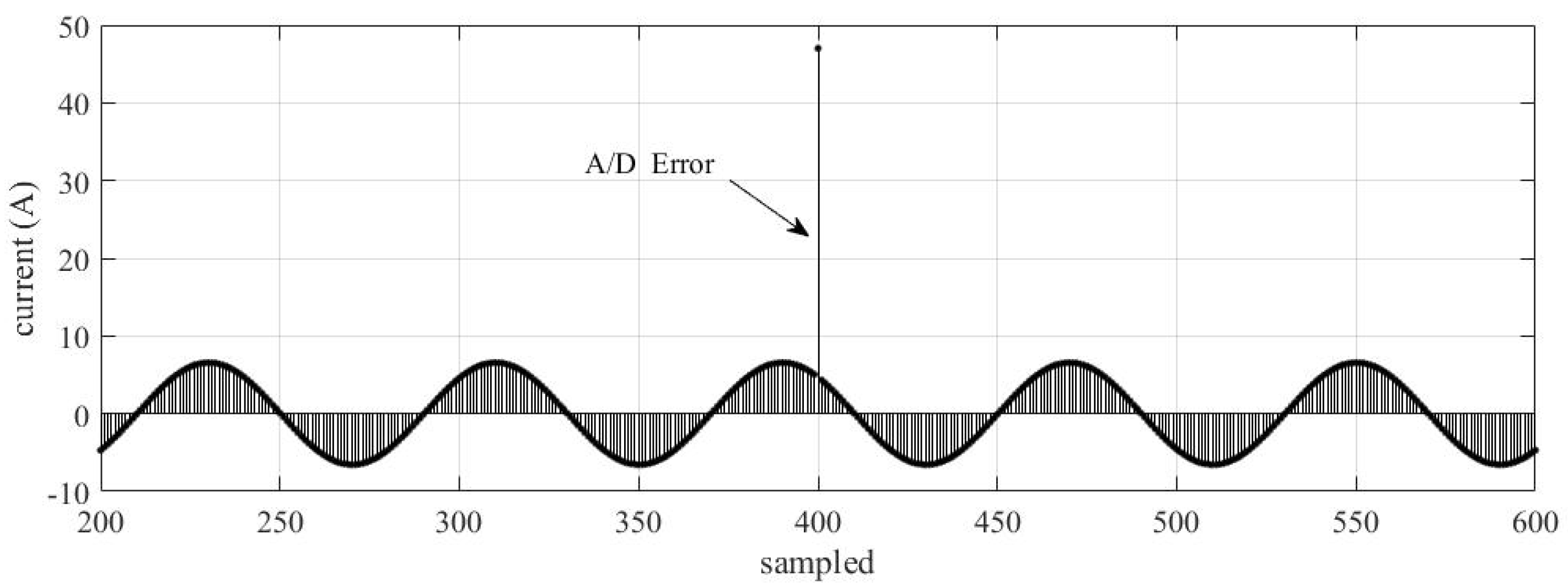
The A/D error is a problem that may occur in the MU signal conditioning circuit. The authors characterized that error as a gain increment in a current or voltage signal sample. Normally, it only happens in one phase while the others remain normal. Depending on the magnitude, this error can generate an unwanted trip of the instantaneous overcurrent protection function. Figure 6 shows an example of an error in A/D. Even though only one sample is affected by this error, the algorithm for phasor calculation may extend the error for the entire cycle.

3. Methodological Procedure

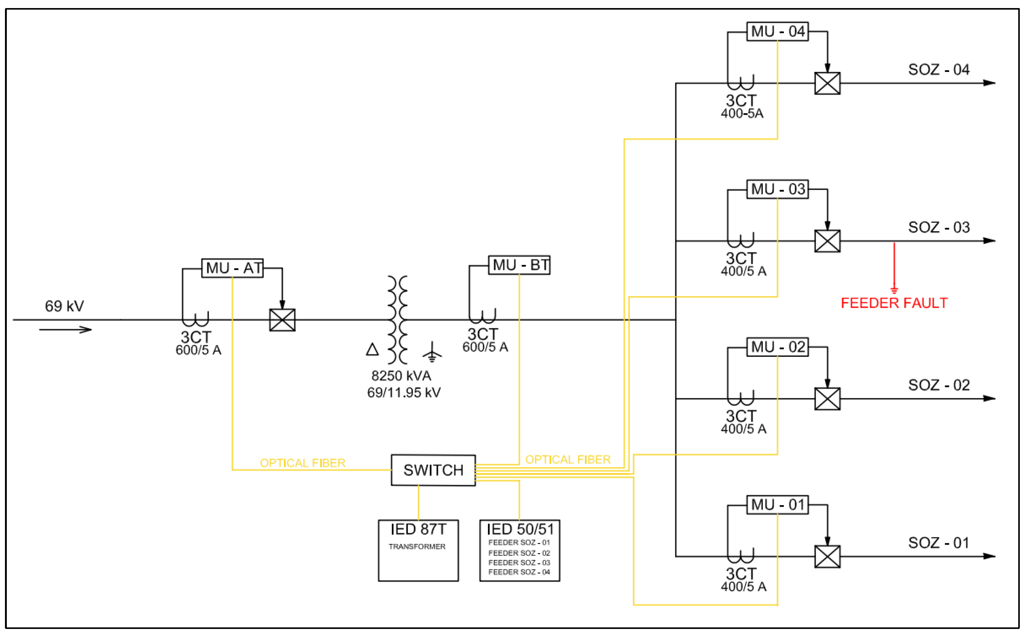
The test system represents a typical 15 kV distribution substation, according to Figure 7. The substation consists of a step-down transformer of 8.25 MVA–69/11.95 kV with 87 function protection and four feeders (SOZ-01 to SOZ-04) protected by 50/51 functions in a single busbar arrangement. Table 2 presents the settings of 50/51 protection functions.
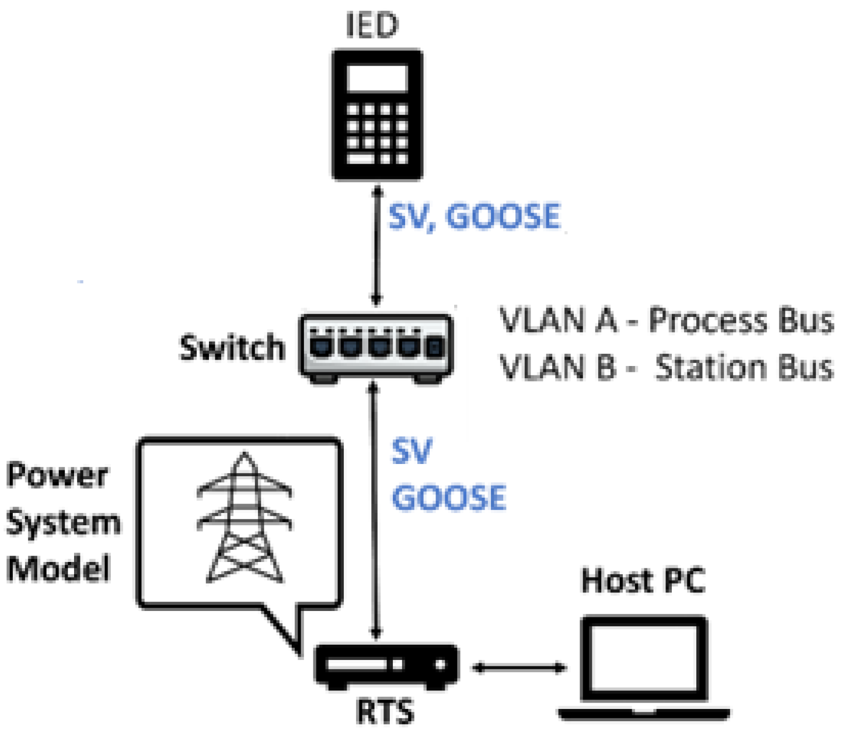
The overcurrent protection evaluation was performed on a real IED with 50/51 functions enabled, considering two operating conditions: normal condition and fault condition in the SOZ-03 feeder. The manipulations were performed by transmitting SV frames according to Table 1. The tripping time includes both the IED time and the GOOSE transmission time. Figure 8 shows the test system reality.
The performance evaluations of the 50/51 functions were carried out by simulating a permanent three-phase fault applied in the beginning of the SOZ-03 feeder. Figure 9 presents the secondary current of phase A for the fault.
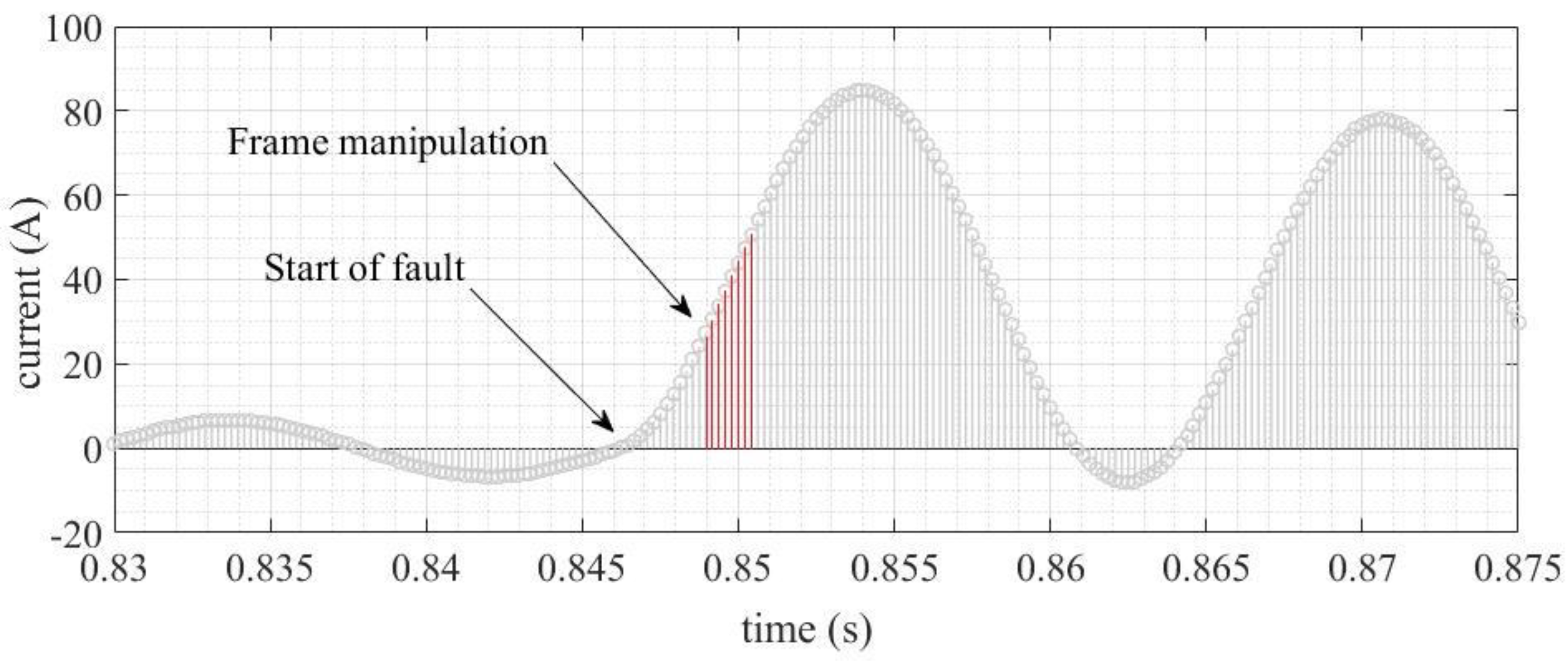
Figure 10 shows the instant occurrence of the three-phase fault. In the following moments, the SV frames are corrupted, according to the manipulations presented in Table 1.

4. Results

4.1. Instantaneous Overcurrent Element (ANSI 50)

The performance evaluation of function 50 was a crucial step in ensuring the reliability and accuracy of the protection system. This evaluation was carried out by simulating a permanent three-phase fault applied at the beginning of the SOZ-03 feeder. Figure 11 illustrates the current of three-phase fault. The simulation was performed to test the response of the system under fault conditions and to identify any potential issues that may arise. The results of these evaluations provide valuable insights into the reliability and accuracy of the protection system when subjected to corrupted frames.
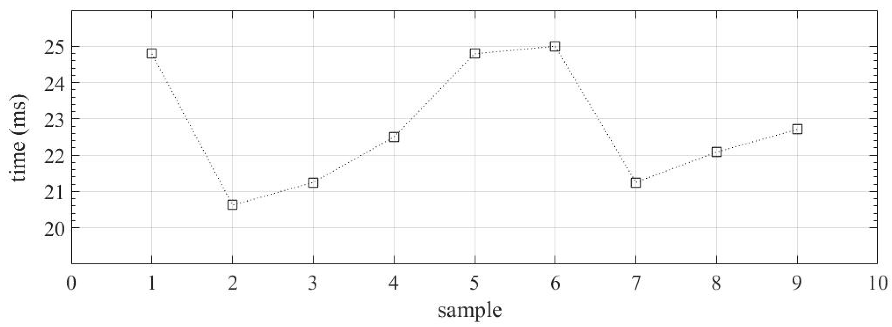
To characterize the tripping time average, the same fault was applied nine times without any SV manipulation. Figure 12 shows the tripping time for all cases. The average tripping time is 22.77 ms. This value will be used as a comparison for cases with SV manipulations.

4.1.1. Packet Loss

The loss of SV packets was carried out for a range of 1 to 1000 lost packets. This was to evaluate the impact of packet loss on the tripping time of the protection system. The results of the evaluation are presented in Figure 13, showing a comparison of the tripping time for the protection, without manipulation and with manipulation. The x-axis of the figure represents the number of lost packets, while the y-axis represents the tripping time in milliseconds.
It is observed from the figure that with an increase in the number of lost packets, the tripping time also increases. The increase in tripping time follows a linear proportion, with a steady increase for every packet lost. This indicates that the more packets that are lost, the more time it takes for the protection system to trip. Therefore, it is crucial to minimize packet loss in the system to ensure accuracy and reliability.

4.1.2. Duplicated Packets

The SV packets were duplicated with different quantities and sequences, according to Figure 14. It can be observed that the protection tripping time was affected when more than five duplications of the packages occurred. In these situations, the trip time tended to have extremely high values. In the other cases, small errors were observed.

4.1.3. Delayed Packets

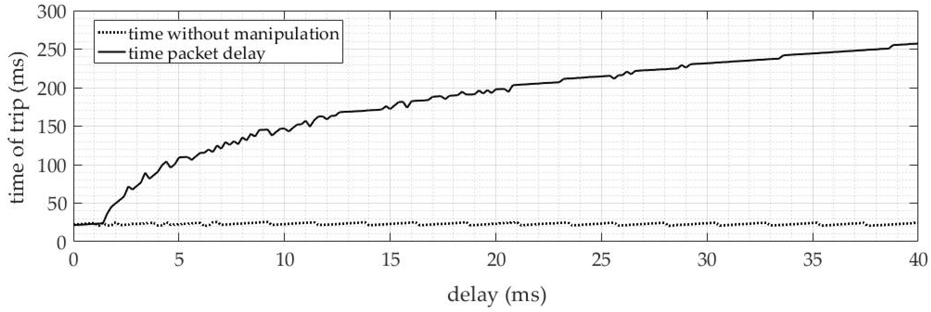
The delays in the SV messages were applied with a variation of 200 us (equivalent to the time of one sample) up to 40 ms. With approximately 3 ms of delay, the tripping time doubles, and with 5 ms, the time already exceeds 100 ms. With 40 ms of delay, the time exceeds 250 ms. In this way, it is observed that the IED is extremely affected by the delay of the SV packets.
Figure 15 shows the tripping results in ms comparing a condition without delay and another with the delay applied. The presentation clearly shows this trend, with tripping times increasing significantly with the increase in delay, and it is essential to monitor these results to ensure the safety and reliability of the system.

4.1.4. SmpCnt Manipulation

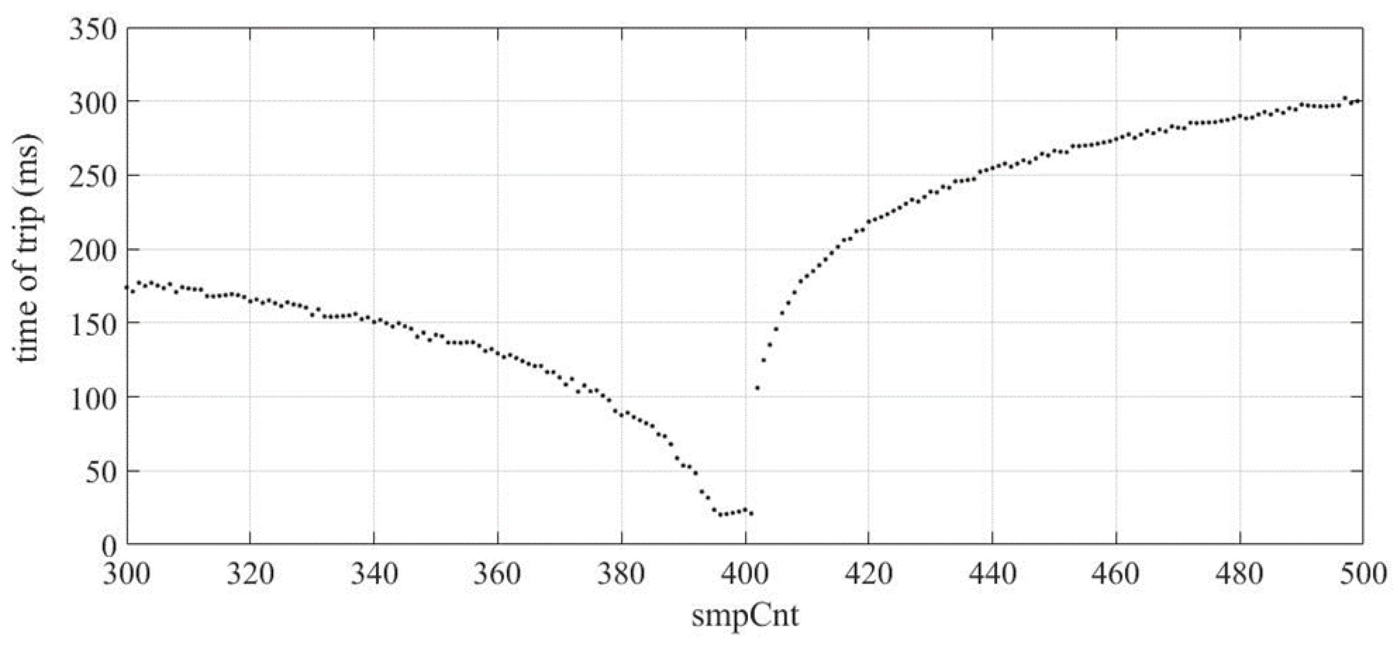
SmpCnt is considered important information to organize SV frames in the IED buffer. This type of manipulation presented the largest delays in the performance of the ANSI 50 protection function. When smpCnt is changed from its current value to a different one, a significantly increased tripping time is observed.
Figure 16 provides the results obtained through the manipulation of smpCnt. It is possible to note that the most significant errors occur when there is a change to distant values from the correct one, which is 4000. On the other hand, when smpCnt is changed to values close to the current value, such as from 400 to 399, for example, the observed errors are much smaller.

4.1.5. A/D Error on MU

Table 3 presents the results of the tests performed with the A/D error on a sample of phase A. The data revealed that the analyzed IED did not trip in the performed cases. Specifically, when the gain exceeded 500, the rms current exceeded the IED’s protection threshold. In this situation, the IED was able to detect the error and treat the data to avoid an improper actuation.

4.2. Inverse Time-Overcurrent Element (ANSI 51)

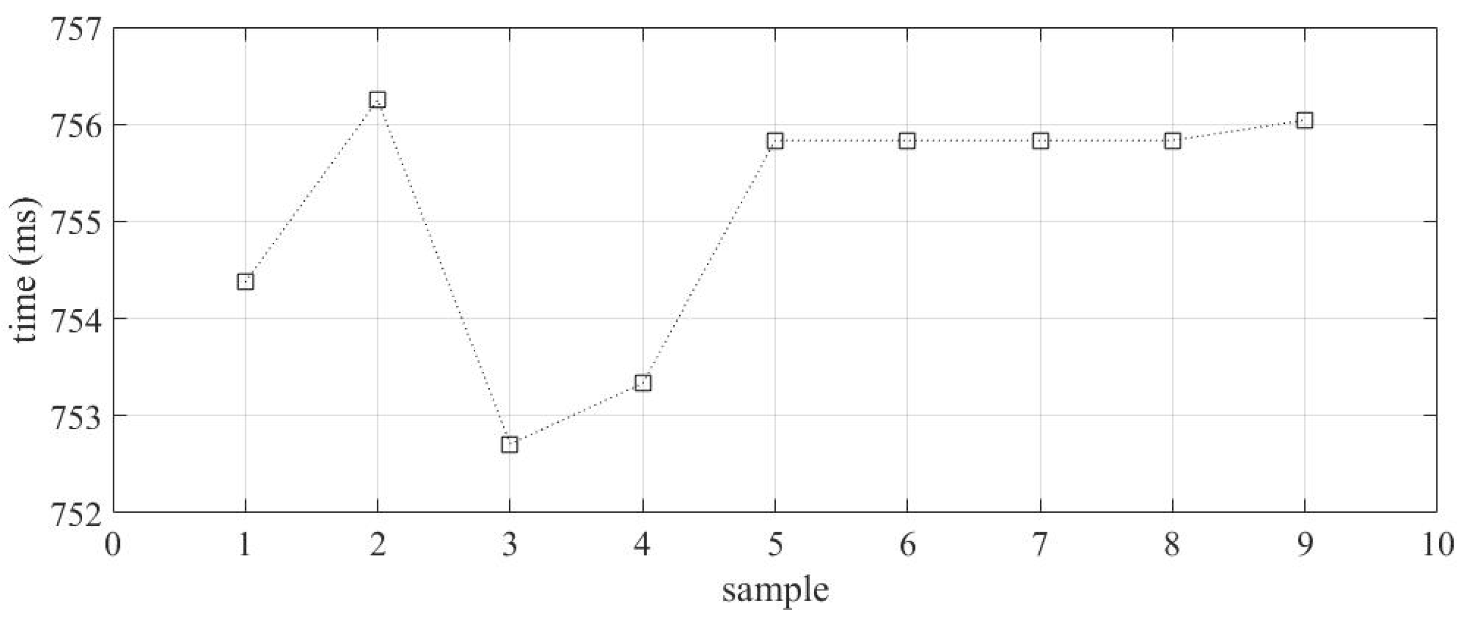
The performance evaluation of function 51 of the IED was carried out through simulations of three-phase faults on the SOZ-03 feeder. The aim is to analyze the ability of the IED to correctly identify and act in the case of overcurrent. Figure 17 presents the results of the secondary current of phase A during the simulated fault. To ensure the accuracy of the results, the same fault was applied nine times, and we used this to characterize the average tripping time of the IED.
The tripping time for all cases tested without SV manipulation was measured and recorded. From these data, it was possible to calculate the average tripping time of 755.83 ms. This value will be used as a comparison point when SV manipulations are taken into consideration. This allows one to evaluate the effectiveness of the IED operation when subjected to SV package manipulation.

4.2.1. Loss of SV Packets

Figure 18 summarizes the results obtained from the packet loss tests. Losses of up to 1000 sample values were carried out. The y-axis represents the tripping time in ms of the IED, and the x-axis represents the number of lost packets. It is possible to observe that as the number of lost SV packets increases, function 51 becomes increasingly affected. When the number of lost packets exceeds 30 samples, a significant difference in the tripping time of function 51 can be noticed.
On the other hand, small quantities of packet loss in SV do not have a significant impact on the tripping time of the function. It is important to note that these results are important to evaluate the reliability of the IED and ensure that it can continue to operate efficiently, even when there is loss in SV packets.

4.2.2. Duplicate Packets

Packet duplication in timed-overcurrent protection (ANSI 51) has shown a significant increase in the IED tripping time. To conduct the test, 30 samples of SV packets were duplicated, and then two SV packets were duplicated in sequence up to five packets in sequence. Figure 19 presents a summary of the results obtained from the duplication test. As can be observed, trip times increase significantly when there is a duplication of 20 packets or more. As the number of duplicated packets in the sequence increases, the trip time of protection also increases proportionally. This highlights the importance of maintaining the integrity of SV packets during data transmission to ensure efficient and reliable performance of the IED.

4.2.3. Delayed Packets

Packet delay in ANSI 51 protection function has a significant impact on the performance of the protection function, as seen in previous cases. Figure 20 shows a comparison between the function 51 protection without SV manipulation and with packet delay. It can be observed that from 2 ms delay, the protection action times begin to increase significantly. When the delay reaches 40 ms, the action time reaches 800 ms.

4.2.4. SmpCnt Manipulation

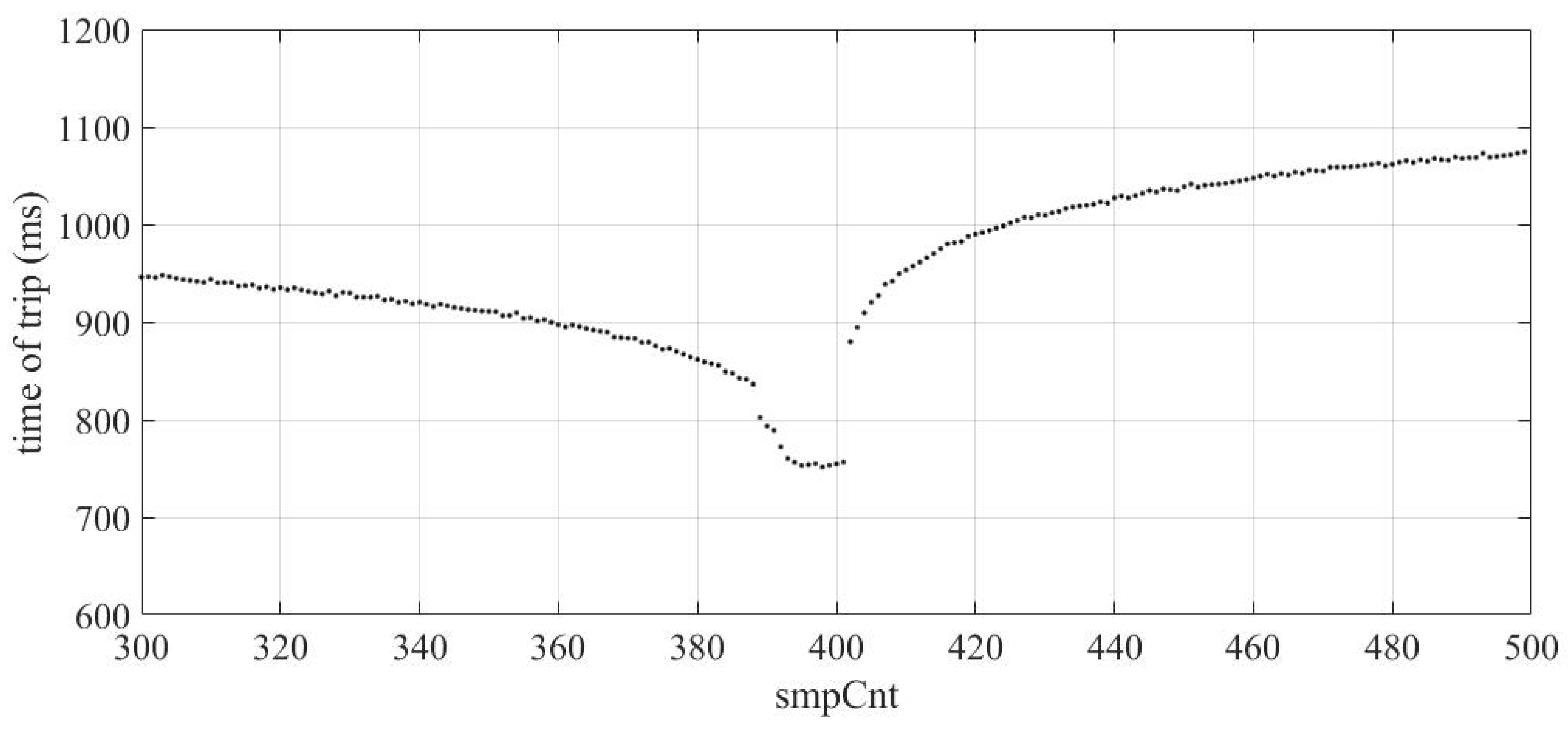
The operating conditions of the protection function were tested using manipulation of the smpCnt parameter and demonstrated similar behavior, as previously seen in Section 4.1.4 where a significant impact on the operation time of the protection was observed. As shown in Figure 21, when the smpCnt value was set at 400 and then changed to a different value, a significant deviation in the tripping time was observed.

4.2.5. A/D Error

The operation of the ANSI 51 protection function submitted to MU A/D errors demonstrated stability. Table 4 shows the obtained results. The currents generated by the error show that from the second test, the currents have already exceeded the protection values.

5. Comparative Manipulation/Protection

Table 5 summarizes the errors generated in the two protection functions analyzed considering the manipulation of SV streams. As can be seen, some errors can significantly affect one protection, and others have a small effect or no effect on the protection function.
It is noteworthy that the effects of manipulations of the SV frames were analyzed under conditions expected for the IED trip. In the case of normal operation (no fault or overload), 50 and 51 protection functions are not affected by SV errors.

6. Conclusions

The GOOSE protocol is already established in several substations worldwide. However, only recently have studies of the SV protocol gained greater emphasis. Because of this, there is still a scarcity of publications, primarily those seeking to evaluate the impacts of corrupted SV frames on commercial IEDs.
Currently, manufacturers of IEDs do not deal with these problems, and they normally block the protection function when the quality of the message is not good. Consequently, a delay in the performance of protection is observed. This article proposed several tests of corrupted SV frames to measure the effects on the tripping times of functions 50/51 of a real IED.
It will be possible to verify the impact of each type of network problem/data integrity on the operation of the protection system. This type of information will be applied in developing design guidelines, monitoring, maintenance, and development of more efficient and safe algorithms. The results show that the data communication layer plays a fundamental role in the performance and reliability of modern protection systems, because SV data’s integrity directly affects the behavior of protection functions.

Author Contributions

Conceptualization, D.A.C.L. and W.S.H.; Methodology, Â.F.S.; Validation, A.P.d.M.; Formal analysis, U.C.N.; Supervision, D.P.B. All authors have read and agreed to the published version of the manuscript.

Funding

This research was financed by CPFL Energia, through the Project “PA3083—Methodology for centralized bus differential protection with efficient use of the process bus in accordance with the IEC 61850 Standard”, developed under the Programa P&D ANEEL PD-00063-3083/2021 and partially by the Coordenação de Aperfeiçoamento de Pessoal de Nível Superior—Brasil (CAPES/PROEX)— Finance Code 001.

Data Availability Statement

Not applicable.

Acknowledgments

The authors are grateful to the Federal Institute of Education, Science and Technology Farroupilha, for the technical and financial support of CPFL Energia in the Project “PA3083—Methodology for centralized bus differential protection with efficient use of the process bus in accordance with the IEC 61850 Standard”, to Program P&D ANEEL. They are also grateful to the coordination for the improvement in higher education personnel—Brazil (CAPES/PROEX)—for the partial funding of this project.

Conflicts of Interest

The authors declare no conflict of interest.

References

  1. Bhattacharjee, T.; Jamil, M.; Alotaibi, M.A.; Malik, H.; Nassar, M.E. Hardware Development and Interoperability Testing of a Multivendor-IEC-61850-Based Digital Substation. Energies 2022, 15, 1785. [Google Scholar] [CrossRef]
  2. Mirzoevich, B.G.; Kholnazarovich, M.S.; Nazrimadovich, I.O.; Ayombekovich, R.O. Review of Modern Methods for Busbar Protection Implementation. In Proceedings of the 2020 International Youth Conference on Radio Electronics, Electrical and Power Engineering (REEPE), Moscow, Russia, 12–14 March 2020; pp. 1–6. [Google Scholar]
  3. Adewole, A.C.; Tzoneva, R. Impact of IEC 61850-9-2 Standard-Based Process Bus on the Operating Performance of Protection IEDS: Comparative Study. In Proceedings of the 19th World Congress, Cape Town, South Africa, 24–29 August 2014. [Google Scholar]
  4. Song, M.-H.; Kang, S.-H.; Lee, N.-H.; Nam, S.-R. IEC 61850-Based Centralized Busbar Differential Protection with Data Desynchronization Compensation. Energies 2020, 13, 967. [Google Scholar] [CrossRef] [Green Version]
  5. Hong, J.; Ishchenko, D.; Kondabathini, A. Implementation of Resilient Self-Healing Microgrids with IEC 61850-Based Communications. Energies 2021, 14, 547. [Google Scholar] [CrossRef]
  6. Firouzi, S.R.; Vanfretti, L.; Ruiz-Alvarez, A.; Hooshyar, H.; Mahmood, F. Interpreting and Implementing IEC 61850-90-5 Routed-Sampled Value and Routed-GOOSE Protocols for IEEE C37.118.2 Compliant Wide-Area Synchrophasor Data Transfer. Electr. Power Syst. Res. 2017, 144, 255–267. [Google Scholar] [CrossRef] [Green Version]
  7. IEC. IEC 61850: Communication Networks and Systems for Power Utility Automation; IEC: Geneva, Switzerland, 2013. [Google Scholar]
  8. Kim, M.-S.; Kang, S.-H. Centralized Multiple Back-Up Protection Scheme with Sharing Data between Adjacent Substations Based on IEC 61850. Energies 2022, 15, 4195. [Google Scholar] [CrossRef]
  9. Apostolov, A. The Impact of IEC 61850 on Transmission and Distribution Substations Busbar Protection. In Proceedings of the 12th IET International Conference on Developments in Power System Protection (DPSP 2014), Copenhagen, Denmark, 31 March–3 April 2014; pp. 1–6. [Google Scholar]
  10. Memon, A.A.; Kauhaniemi, K. Real-Time Hardware-in-the-Loop Testing of IEC 61850 GOOSE-Based Logically Selective Adaptive Protection of AC Microgrid. IEEE Access 2021, 9, 154612–154639. [Google Scholar] [CrossRef]
  11. Westman, J.; Hadidi, R.; Fox, C.; Leonard, J.; Harrell, A. Controller Hardware-in-the-Loop Testing of an IEC 61850 GOOSE Based Control for Seamless Transition of a Microgrid Between Island and Grid-Connected Modes. IEEE Trans. Ind. Appl. 2021, 57, 61–69. [Google Scholar] [CrossRef]
  12. Patil, M.; Bhide, S.R.; Bhat, S.S. Experimenting with IEC 61850 and GOOSE Messaging. In Proceedings of the 2017 4th International Conference on Power, Control & Embedded Systems (ICPCES), Allahabad, India, 9–11 March 2017; pp. 1–6. [Google Scholar]
  13. Habib, H.; Fawzy, N.; Brahma, S. Hardware in the Loop Testing of a Protection Scheme for Microgrid Using RTDS with IEC 61850 Protocol. In Proceedings of the 2020 IEEE Industry Applications Society Annual Meeting, Detroit, MI, USA, 10–16 October 2020; pp. 1–8. [Google Scholar]
  14. Shoaib, M.; Vanfretti, L. Performance Evaluation of Protection Functions for IEC 61850-9-2 Process Bus Using Real-Time Hardware-in-the-Loop Simulation Approach. In Proceedings of the 22nd International Conference and Exhibition on Electricity Distribution (CIRED 2013), Stockholm, Sweden, 10–13 June 2013; pp. 1–4. [Google Scholar]
  15. Kang, B.; Maynard, P.; McLaughlin, K.; Sezer, S.; Andrén, F.; Seitl, C.; Kupzog, F.; Strasser, T. Investigating Cyber-Physical Attacks against IEC 61850 Photovoltaic Inverter Installations. In Proceedings of the 2015 IEEE 20th Conference on Emerging Technologies & Factory Automation (ETFA), Luxembourg, 8–11 September 2015; pp. 1–8. [Google Scholar]
  16. Mocanu, S.; Thiriet, J.-M. Real-Time Performance and Security of IEC 61850 Process Bus Communications. JCSANDM 2021, 10, 1–42. [Google Scholar] [CrossRef]
  17. Kanabar, M.G.; Sidhu, T.S.; Zadeh, M.R.D. Laboratory Investigation of IEC 61850-9-2-Based Busbar and Distance Relaying with Corrective Measure for Sampled Value Loss/Delay. IEEE Trans. Power Deliv. 2011, 26, 2587–2595. [Google Scholar] [CrossRef]
  18. Hariri, M.E.; Youssef, T.A.; Habib, H.F.; Mohammed, O. Online False Data Detection and Lost Packet Forecasting System Using Time Series Neural Networks for IEC 61850 Sampled Measured Values. In Proceedings of the 2017 IEEE Power & Energy Society Innovative Smart Grid Technologies Conference (ISGT), Washington, DC, USA, 23–26 April 2017; pp. 1–5. [Google Scholar]
  19. Yu, L.; Zhang, S.; Wu, N.; Yu, C. FPGA-Based Hardware-in-the-Loop Simulation of User Selection Algorithms for Cooperative Transmission Technology Over LOS Channel on Geosynchronous Satellites. IEEE Access 2022, 10, 6071–6083. [Google Scholar] [CrossRef]
  20. Bian, D.; Kuzlu, M.; Pipattanasomporn, M.; Rahman, S.; Wu, Y. Real-Time Co-Simulation Platform Using OPAL-RT and OPNET for Analyzing Smart Grid Performance. In Proceedings of the 2015 IEEE Power & Energy Society General Meeting, Denver, CO, USA, 26–30 July 2015; pp. 1–5. [Google Scholar]
Figure 1. SV packet captured in Wireshark software.
Energies 16 03386 g001
Figure 2. Current signal with 25 packets lost.
Energies 16 03386 g002
Figure 3. Current signal with packet duplicate. (a) Duplicate packet. (b) Duplicate packet in sequence.
Energies 16 03386 g003
Figure 4. Current signal with packet delay.
Energies 16 03386 g004
Figure 5. smpCnt value (a) without manipulation; (b) with reduction in the value of smpCnt; (c) with increase in the value of smpCnt.
Energies 16 03386 g005
Figure 6. Current signal with A/D error.
Energies 16 03386 g006
Figure 7. Substation test system.
Energies 16 03386 g007
Figure 8. Simulation test system.
Energies 16 03386 g008
Figure 9. Three-phase fault current—phase A—without SV manipulation condition.
Energies 16 03386 g009
Figure 10. Instantly initiate faults and perform detailed package manipulations.
Energies 16 03386 g010
Figure 11. Three-phase fault current—phase A—without SV manipulation condition.
Energies 16 03386 g011
Figure 12. Tripping time (IED processing + GOOSE) for ANSI 50.
Energies 16 03386 g012
Figure 13. Tripping time results ANSI 50—packets loss.
Energies 16 03386 g013
Figure 14. Tripping time results ANSI 50—duplicated packets.
Energies 16 03386 g014
Figure 15. Tripping time results ANSI 50—delayed packets.
Energies 16 03386 g015
Figure 16. Tripping time results ANSI 50—smpCnt manipulation of SV packets.
Energies 16 03386 g016
Figure 17. Tripping time (IED processing + GOOSE) for ANSI 51.
Energies 16 03386 g017
Figure 18. Tripping time results ANSI 51—loss of SV packets.
Energies 16 03386 g018
Figure 19. Tripping time results ANSI 51—duplicate of SV packets.
Energies 16 03386 g019
Figure 20. Tripping time results ANSI 51—delay of SV packets.
Energies 16 03386 g020
Figure 21. Tripping time results ANSI 51—smpCnt manipulation of SV packets.
Energies 16 03386 g021
Table 1. Manipulations into the sampled value publisher messages.
Type of ManipulationDescription
1Stop transmissionSimulate the loss of packets on the network by stopping the SV publishing during a certain number of frames.
2Delay transmissionSimulate an unwanted delay on the network by delaying the frames for a specified amount of time, in us.
3Duplicate transmissionSimulate a wrong network topology where packets could be sent multiple times by duplicating frames for a certain number of frames.
4smpCnt manipulationSimulate an IED clock reset by manipulating the smpCnt of a given frame.
5smpSynch manipulationSimulate a loss of synchronization by manipulating the smpSynch of a stream for a certain number of frames.
6Quality manipulationSimulate a change in the IED performance by manipulating the quality of the voltage and cur-rent values in a stream.
7A/D errorSimulates an error in the analog/digital (A/D) converter of a Merging Units.
Information extracted from the Hypersim software manual.
Table 2. Parametrization of 50/51 protection functions.
ParameterPhaseNeutral
Pickup current (51)400 A120 A
Pickup current (50)2400 A2000 A
Curve typesIEC standard inverse (C1)IEC standard inverse (C1)
Time dial0.150.30
CT raio400/5 A400/5 A
Table 3. Results of ANSI 50—A/D error on MU.
Gain in ErrorOperationCurrent Error (A rms)
100correct9.23
500correct31.96
1000correct60.96
2000correct118.8
5000correct294.7
Table 4. Information of A/D error of MU in real IED for protection ANSI 51.
Gain in ErrorOperationError Current rms (A)
100correct9.18
500correct31.97
1000correct60.80
2000correct121.4
5000correct297.6
Table 5. Comparison between protections and manipulations.
ErrorANSI 50ANSI 51
Loss Packetsaffectedaffected
Duplicate Packetsaffectedaffected
Delay Packetsaffectedaffected
smpCnt manipulationaffectedaffected
A/D ErrorUnaffectedUnaffected
Disclaimer/Publisher’s Note: The statements, opinions and data contained in all publications are solely those of the individual author(s) and contributor(s) and not of MDPI and/or the editor(s). MDPI and/or the editor(s) disclaim responsibility for any injury to people or property resulting from any ideas, methods, instructions or products referred to in the content.