Abstract
Brush seals can improve engine performance by reducing leakage. Wear models of brush seals provide methods to predict wear and leakage. However, rotor eccentricity, radial deformation, and hysteresis effect of bristles are not considered systematically in the existing models, which may lead to large errors in some cases. To investigate the influence of rotor-stator eccentricity and radial deformation on the wear process and leakage performance of brush seal, a brush seal test was planned and executed, in which the air leakage rates were measured at different testing times and operating conditions, the eccentricity and radial deformation was measured using eddy current sensors. The test results showed that the eccentricity and radial deformation significantly affected the wear behavior and leakage performance. In the theoretical research, the abrasive wear equation is adopted to describe the material loss of bristles, and a simplified description is used to express the rotor-stator eccentric motions. To describe the effect of hysteresis on wear behavior, the deformation of the bristle pack is divided into rebounding deformation and locked deformation, and the two deformation modes are modeled separately. Then a brush seal wear model considering rotor-stator eccentricity and radial deformation is obtained, in which the hysteresis effect is especially represented. The wear model was verified quantitatively based on the brush seal test data, and the results show that there is an error of 20% with the calculated wear loss when rotor eccentricity, radial deformation, and hysteresis effect are comprehensively considered. In contrast, ignoring the hysteresis effect may increase the error by several times. This study provides a quantitative and practical method for predicting the wear and leakage of brush seals.
1. Introduction
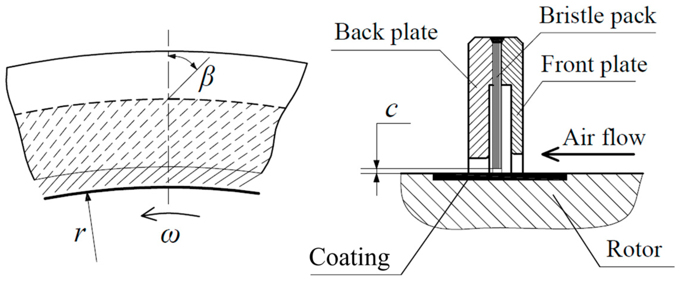
A brush seal is a type of flexible contact seal that could meet the high-speed and high-temperature conditions of turbomachinery. Brush seals are widely used in aero-engines, gas turbines, and steam turbines and have produced significant economic benefits. As shown in Figure 1, a typical brush seal consists of a front plate, a back plate, a bristle pack, and the rotor. Due to the good elasticity of the bristle pack, contact and friction between the rotor and bristle pack are allowed, so a zero initial clearance or negative initial clearance is acceptable for the brush seal. In contrast, additional radial clearance is generally required by labyrinth seals in order to avoid collision between the rotor and seal. Under ideal conditions, the leakage of a brush seal can be less than 10% of that of a labyrinth seal at the same assembly location [1]. In addition, even considering the effect of wear, the leakage of a brush seal will generally not exceed 50% of that of a labyrinth seal [2]. Due to the close relationship between wear and leakage, many researchers have spent efforts on the wear behavior of brush seals. Menendez et al. [3] discussed the wear behavior of brush seals on large industrial gas turbines and proposed that the initial interference of brush seals should be minimized in order to properly manage heat generation and wear at the sliding interface. Ha et al. [4] used optical equipment and a computer vision algorithm to measure the radial clearance of a worn brush seal, the leakage gap was revised by the measured clearance between the rotor and brush ring, and then a small error of 4% was reached between predicted leakage and the experimental data. Gail et al. [5] provided an average wear trend based on mechanical inspection results of eight engines of a military project after extensive development and certification testing. Hildebrandt et al. [6], Chupp et al. [7], Sun et al. [8], and Sun Xiaoping [9] also discussed the wear process by analyzing their brush seal test data, and the testing data consistently indicated that brush seals wear faster at the early stage of operation.

Figure 1.
Structure of brush seal.
The above tests or statistical data showed the objective law of wear behaviors of brush seals. However, to quantitatively predict the wear and performance loss of brush seals, it is necessary to build a quantitative wear model. Some researchers have also conducted this work. Fellenstein et al. [10] used a negative exponential formula to describe the variation of interference with time, which reflected that brush seals wear quickly in the initial stage and wear slowly in the later stage. However, this simple empirical formula only included the initial interference and a wear rate coefficient—a series of influencing factors that are simplified. Prior et al. [11] analyzed the wear rate of brush seals based on adhesive wear and Archard wear model and gave a wear formula in integral form. Kirk et al. [12] reported the progress of Cross Manufacturing Co. on brush seal design method and process and mentioned that they had developed a calculation program for the wear behavior of brush seals. However, the detailed mathematical model was not introduced. Fan et al. [13] established a differential equation and presented the analytic solutions to estimate the wear volume of brush seals, and the analytic solutions contained a negative exponential term similar to the reference [10]. In Fan’s model, the wear volume of the brush seal was a function of multiple parameters and variables, including interference, pressure drop, rotating speed, gas temperature, seal bore diameter, bristle diameter, bristle pack lay angle, and the thickness of the bristle pack. However, the rotor vibration and the hysteresis effect were not represented clearly and directly in the wear models described above, and this may lead to a large deviation in wear calculation. So further experimental and theoretical studies are needed to improve the accuracy of wear calculation for brush seals.
In Section 2, a specially designed 22-h brush seal test is introduced in detail. The air leakages were measured repeatedly at different testing times and operating conditions during the test, and the test result shows that the rotor vibration and hysteresis effect significantly affect the performance and wear behavior of brush seals. In Section 3, the wear process of brush seal and its influencing factors are analyzed systematically, and a wear model considering eccentricity and radial deformation is provided, especially the hysteresis effect of bristles is also specifically considered. In Section 4, comparative analysis results show that the wear and leakage behaviors of the tested brush seals could be well explained by the established wear model. The air leakage variation in the test shows that the radius wear is about 0.04 mm at the 12th hour. By considering rotor eccentricity, radial deformation, and hysteresis effect comprehensively as the established model, the calculated radius wear at the 12th hour is 0.05 mm which is close to the experiment value. In contrast, the error of the calculated wear loss may be several times the experimental result when some factors are ignored. In conclusion, the research provides a practical brush seal wear model which shows better adaptability to various operating conditions and brush seal structural parameters.
2. Experimental Research
2.1. Experimental Method and Process
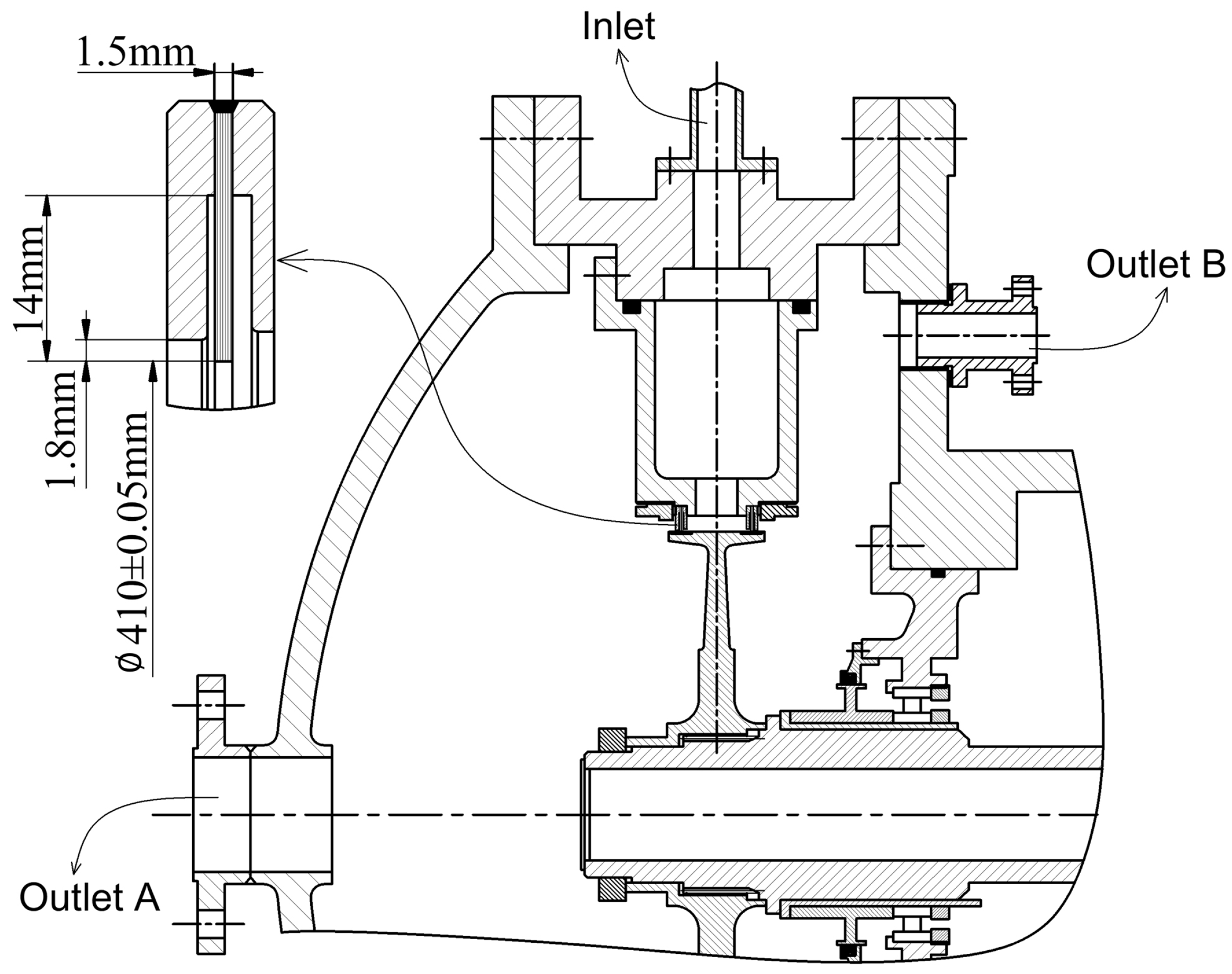
Figure 2 illustrates the structure of the test section, in which a pair of brush rings were installed inside the cavity. The air flow inlets were between the two brush rings, and the outlets were arranged on both sides of the test section. This installation scheme could effectively reduce the axial load acting on the bearings of the test rig. Main dimensions of the tested brush seals are noted in Table 1 and Figure 2, where the bristle bore diameter was the rotor diameter was mm. The rotor was machined using 1Cr13 stainless steel and was sprayed with tungsten carbide wear-resistant coating. Inconel 718 was chosen as the bristle material, and 1Cr13 stainless steel was also used to manufacture the front plate and the back plate of brush rings. Materials of the wear-resistant coating and brush bristles were both common materials for brush seals.

Figure 2.
Structure of the test section.

Table 1.
Geometry parameters of the tested brush seals.
Compressed air was supplied by two air compressors and a pressure stabilizing vessel. A vortex flowmeter and an electric control valve were installed on the inlet piping. The air flow rate and pressure difference could be adjusted in real-time during the test. A high-power air heater was also installed on the inlet piping, and the air temperature can be set to a certain range by adjusting the heating power. Table 2 lists the main testing parameters monitored and recorded during the test and shows the measurement range and accuracy.

Table 2.
Tested parameters.
As shown in Table 3, the testing process contained four running stages. The rotating speed was 4660 r/min in the first two stages and 11,190 r/min in the last two stages; the two rotating speeds corresponded to the sliding speed of 100 m/s and 240 m/s, respectively. Considering severe wear generally happens at the early running stage, inconsistent running time was adopted for each test stage. The running time length was only one hour in Stage-1 and Stage-3, and the running time was ten hours in Stage-2 and Stage-4. The eccentricity and radial deformation would be different at the two different rotating speeds, which would lead to different wear and leakage performance.

Table 3.
Test parameters for each running stage.
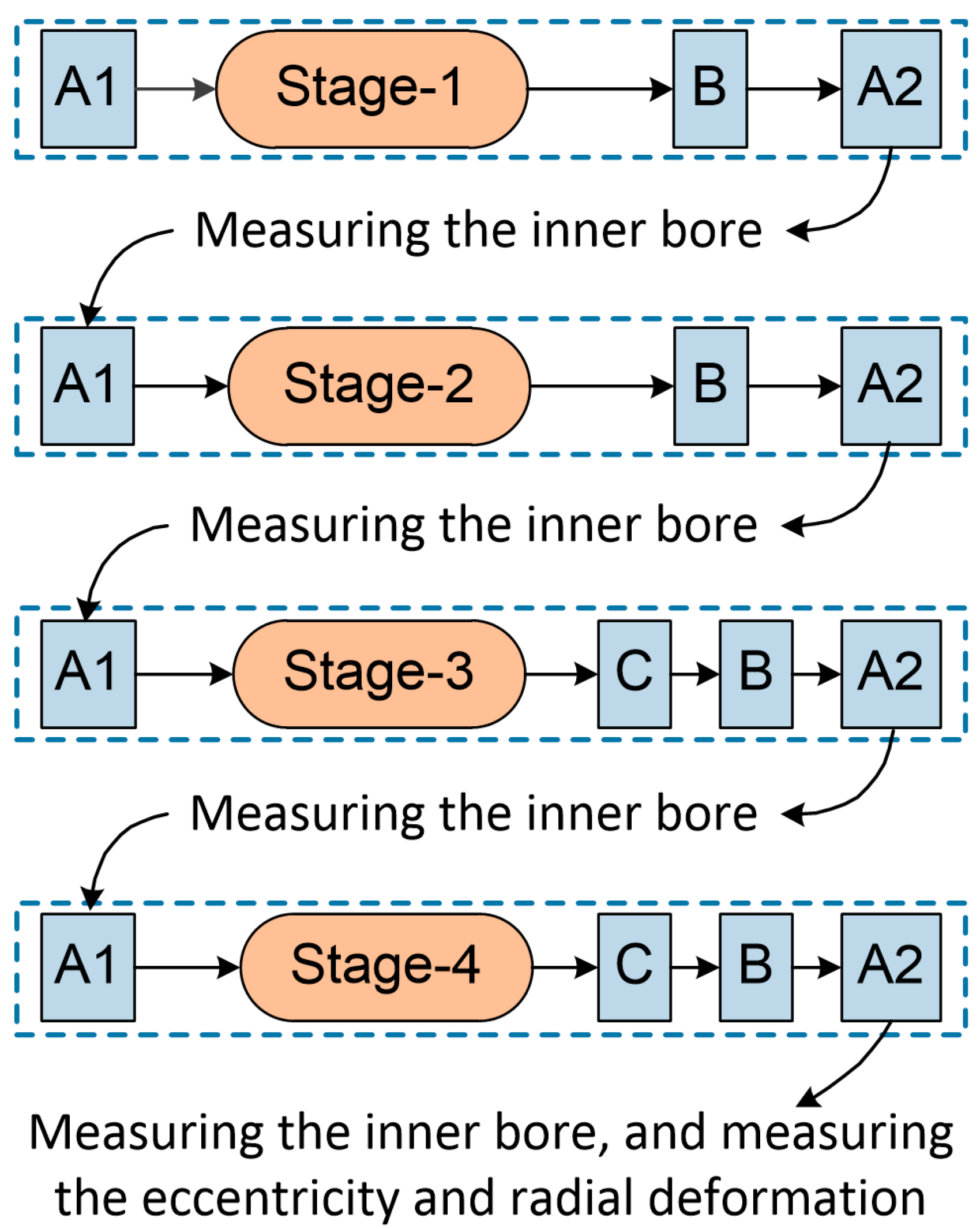
The inlet air temperature was set to 300 ± 10 °C in all the four running stages in order to reduce the influence of temperature difference. During the test, the leakage performance was measured based on the conditions shown in Table 4 (see Section 2.4 for the results). Three rotation speeds, 0 r/min, 4660 r/min, and 11,190 r/min, were included. Before the start of each running stage, leakage rates at zero rotation speed were measured (Condition-A in Table 4). After Stage-1 and Stage-2, leakage rates at 4660 r/min and zero rotation speed were measured (Condition-B and A in Table 4). After Stage-3 and Stage-4, leakage rates at 11190 r/min, 4660 r/min and zero rotation speed were all measured sequentially (Condition-C, B and A in Table 4). Figure 3 shows the detailed plan of the test work. The purpose of not using Condition-C during the first two stages was to avoid unexpected wearing caused by high rotating speed during low rotating running stages. Since Condition-A was used two times before and after running in each stage, in order to distinguish the two measurement results, the leakage performance test before running is marked by “A1”, and the test after running is marked by “A2”. When each running stage ended, the brush ring near the outlet-A was disassembled, and its bristle bore was measured (the results are illustrated in Section 2.2). Although one of the brush rings was disassembled and reinstalled several times during the test, the brush ring was not replaced, and its angular installation position was unchanged. After Stage-4, eddy current sensors were installed on the test rig to measure the rotor-stator eccentricity and radial deformation (the results are illustrated in Section 2.3). The air flow was heated to 300 °C during the test, and the air flow could not be shut down until the temperature of the air heater decreased to a safe level. In the running test and the leakage performance measuring work, the pressure difference kept higher than 40 kPa, the reason for emphasizing this is that the continuous airflow is associated closely with the hysteresis behavior mentioned later.

Table 4.
Measuring conditions for leakage performance.

Figure 3.
Schematic diagram of test procedure.
2.2. Observation and Measurement of Wear
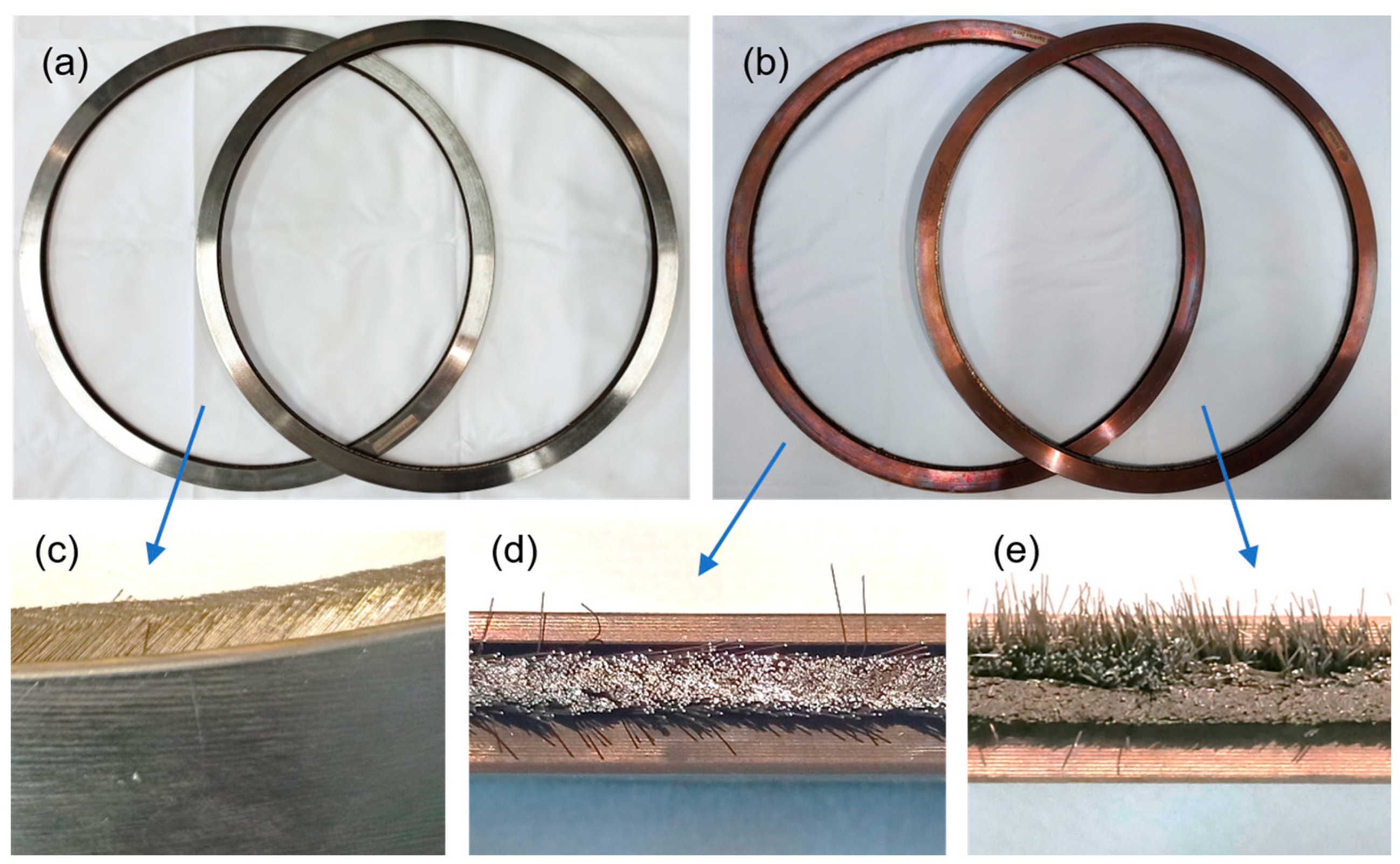
Figure 4 shows the appearance of the tested brush rings. The color of the front plates and back plates was silver–white before the test and changed to brass due to the oxidation of high-temperature air when the test ended. After the test, wear and plastic deformation appeared on the bristle pack, as shown in Figure 4d,e. In Figure 4e, significant bending deformation occurred on brush bristles near the front plate. This phenomenon was not observed after the test of Stage-1 and Stage-2 but was observed after Stage-3. After Stage-4, about 10% of the bristle pack presented an appearance like in Figure 4e, and the other 90% of the bristle pack was similar to Figure 4d. According to the above observation results, the tested brush rings were worn more significantly at 11,190 r/min than at 4660 r/min.

Figure 4.
The photos of tested brush rings: (a) brush rings before test; (b) brush rings after test; (c) bristle pack before test; (d) wear of brush bristles; (e) wear and plastic deformation of brush bristles.
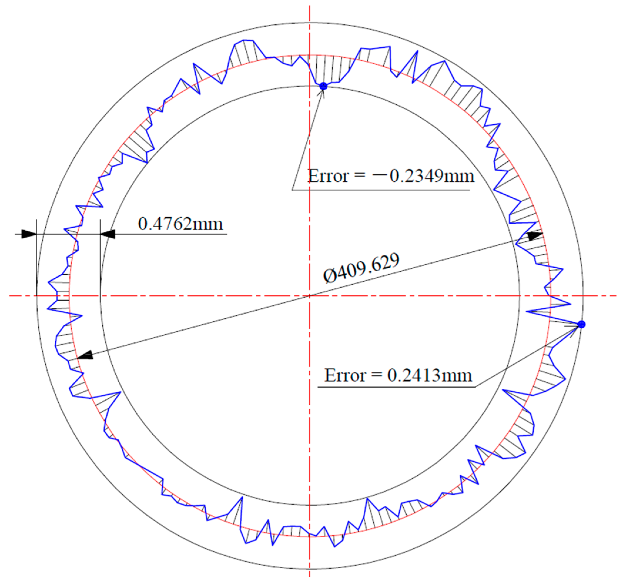
Considering the flexibility of the bristle pack, a non-contact measuring projector was used to measure the brush rings. Figure 5 shows one of the measurement results in an enlarged pattern; it can be seen that the roundness of the profile is not ideal. In addition, the detected diameter in Figure 5 is 409.629, which is smaller than the initially detected diameter 409.860, and this seems unreasonable. The reason is that the brush bristle tips were not aligned ideally, and the measuring projector automatically identified the bulge points of the brush pack, even if the bulge points contained only one bristle. For the above reasons, the dimensional data measured by the measuring projector will not be adopted in this paper; the wear loss and clearance variation will be evaluated by analyzing the air leakages.

Figure 5.
Inner hole profile identified by measuring projector.
2.3. Eccentricity and Centrifugal Deformation of Rotor
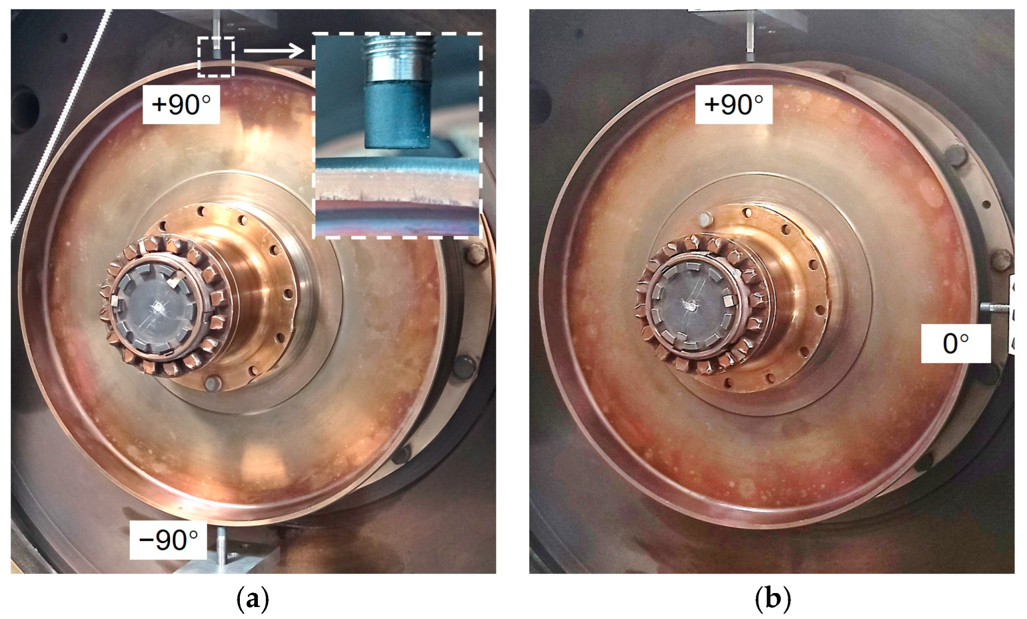
A total of two eddy current sensors were used to measure the eccentricity and centrifugal deformation of the rotor at different rotating speeds. Figure 6 shows the installation of eddy current sensors on the housing of the test rig. In Figure 6a, there was an interval of 180° between the angular positions of two eddy current displacement sensors, and the rotor diameter variation could be obtained directly. In Figure 6b, there was an interval of 90° between the two sensors, and the axis trajectory could be further acquired. What should be noted is that rotor diameter variation must be considered when calculating the axis trajectory. Generally, rotating speed is the most direct and obvious factor which affects the rotor vibration, and the mechanical properties of rotor material (1Cr13 stainless steel) change little from normal temperature to 300 °C. Therefore, the influence of temperature on vibration is ignored in the measurement. A motion platform with a minimum scale of 0.01 mm was used to calibrate the relationship between the gap and the signals of eddy current sensors to ensure test accuracy.

Figure 6.
Installation of eddy current sensors: (a) 180° position interval; (b) 90° position interval.
The rotor centrifugal expansion and vibration amplitude were small at low rotating speed (lower than 1000 r/min), and the clearances between the rotor surface and the sensors kept constant approximately. However, the rotor radial deformation and the vibration became obvious at high speeds. Figure 7 shows the variation of the distance between the sensor detectors and rotor surface during 0.1 s at 11,190 r/min. According to Figure 7, the gaps measured by the sensors decreased by about 0.2~0.3 mm. This means that the rotor radius increased by about 0.2~0.3 mm at 11,190 r/min. The distance value in Figure 7 fluctuated about 18 times during 0.1 s, and this was consistent with the rotation frequency, and it can be seen that the vibration amplitude is about 0.2 mm according to fluctuation.

Figure 7.
Distance variation measured by eddy current sensors at 11,190 r/min: (a) 180° position interval; (b) 90° position interval.
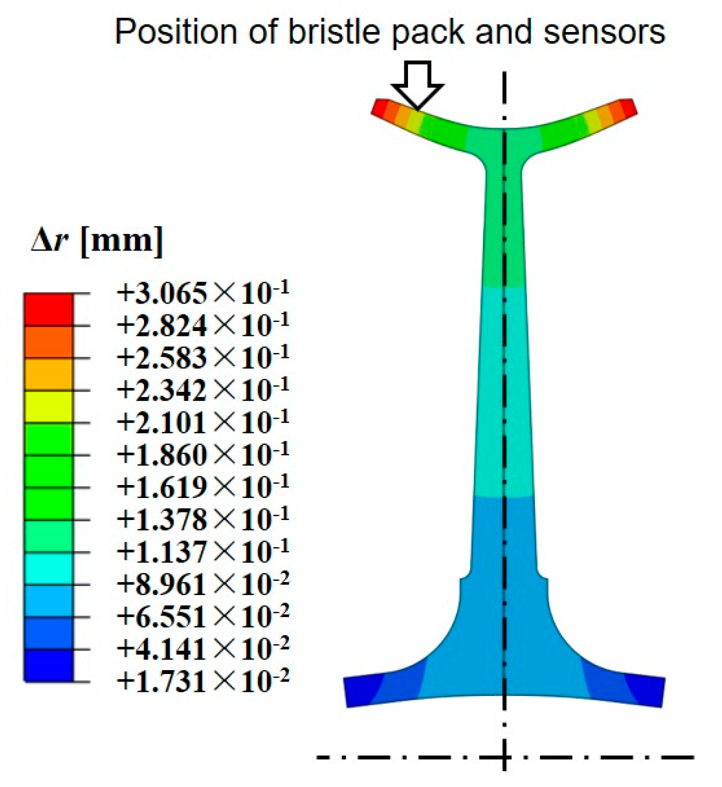
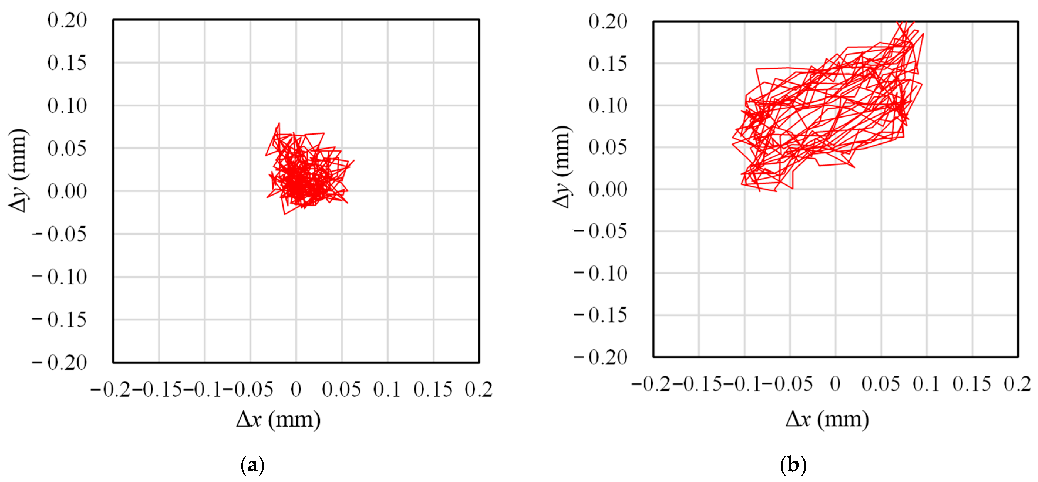
Table 5 shows the measured values of rotor centrifugal expansion and vibration amplitude at 4660 r/min and 11,190 r/min. The centrifugal expansion at 4660 r/min was very small. However, the rotor radius increased by 0.241 mm at 11,190 r/min, and this is a very considerable value. Figure 8 shows the simulation result of rotor deformation. It can be seen that the simulation result of rotor expansion is consistent with the measured value. Figure 9 shows the rotor axis trajectory generated from the measured data. In order to simplify the description of rotor-stator eccentricity, equivalent radius is used to describe the amplitude of rotor-stator eccentricity, and is the radius of a circle roughly equivalent to the eccentric trajectory (indicated in Section 3.2). According to the coverage area of the trajectory in Figure 9, the equivalent radius of eccentricity at 4660 r/min is taken as 0.05 mm, the equivalent radius at 11,190 r/min is taken as 0.1 mm, and the values are listed in Table 5.

Table 5.
Measured values of centrifugal expansion and vibration amplitude.

Figure 8.
Centrifugal expansion simulation of rotor at 11,190 r/min.

Figure 9.
Axis trajectory of the rotor: (a) 4660 r/min; (b) 11,190 r/min.
2.4. Air Leakage Rates
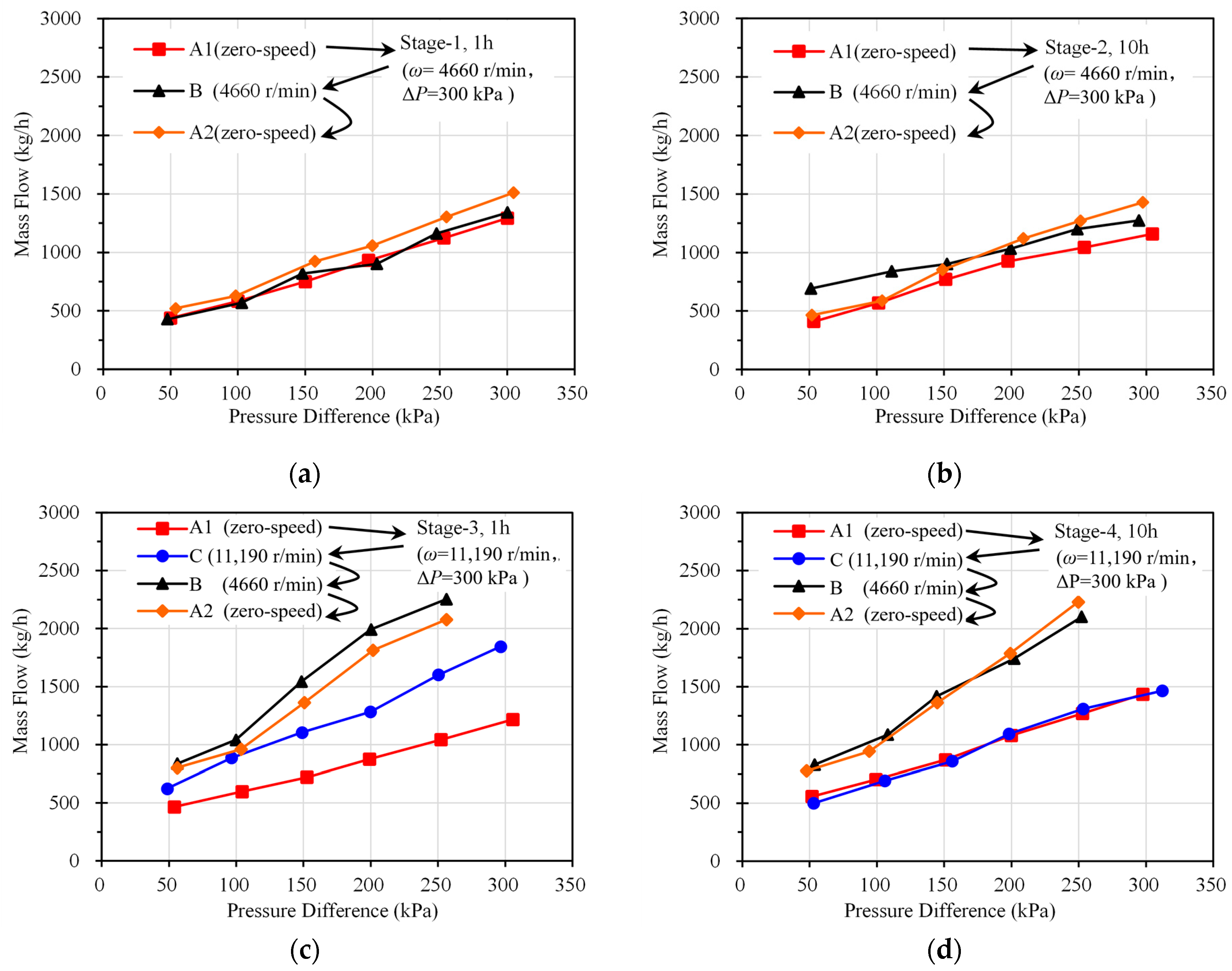
According to Figure 3, three leakage curves would be obtained respectively during Stage-1 and Stage-2, and four leakage curves would be obtained respectively during Stage-3 and Stage-4. These leakage curves are shown in Figure 10. It can be seen from Figure 10a,b that the air leakages changed little in the measurements of the first two stages but varied by a large margin in the measurements of the last two stages. For the leakage measurement results in Stage-3 and Stage-4, the air leakage of Condition-A2 and Condition-B is about double that of the leakage of Condition-A1 and Condition-C. The leakage rates did not increase monotonously with time but were significantly affected by the measuring conditions and time points. The measuring results can be explained by the hysteresis effect; the large eccentricity and radial expansion of the rotor at 11,190 r/min made the hysteresis effect prominent. Since the air leakages of Condition-B and Condition-A2 increased significantly during Stage-3 and Stage-4, the pressure difference could not reach the maximal pressure of 300 kPa due to insufficient air supply of the test system. This led to the missing 300 kPa measuring points in Figure 10c,d.

Figure 10.
Leakage performance results: (a) Leakages before and after Stage-1; (b) Leakages before and after Stage-2; (c) Leakages before and after Stage-3; (d) Leakages before and after Stage-4.
From the above test results, it could be seen that the rotor-stator eccentricity and radial deformation affected the leakage performance significantly. What is complicated is that the leakage rates did not increase monotonously with the test time, and there was a sealing performance recovery phenomenon during the test. This is because the hysteresis effect of the brush seal affected the clearance between the bristle pack and the rotor. In the following, the wear process will be analyzed and modeled systematically, and the influences of rotor-stator eccentricity, radial deformation, hysteresis effect, and other factors will be discussed.
3. Modeling of Brush Seal Wear Behavior
3.1. Force and Deflection Analysis of Brush Bristles
The bristles of the brush seal will deflect when in contact with the surface of the rotor, and the deflection amplitude of the bristles will increase when the rotor is expanding or moving towards the bristles. As shown in Figure 11a, there are normal contact force and friction force at the tip of the bristle when the bristle tip moves from position A to position B due to contact with the rotor. In addition, there are air flow force and friction force acting on the cylindrical surface of the brush bristle. The influence of air flow force can be described by the “blow-down effect”. The friction force is from the adjacent bristles or the back plate and is closely related to the compression of the bristle pack caused by the air flow. When the bristles are pushed by the rotor, the force will lead to the “stiffening effect”, and when the rotor leaves the bristles, the force will lead to the “hysteresis effect”. In Section 3.1, Section 3.2 and Section 3.3, the influence of the hysteresis effect, stiffening effect and blow-down effect are ignored temporarily, and they will be discussed in Section 3.4 and Section 3.5.

Figure 11.
Force analysis of brush bristle: (a) Forces on brush bristle; (b) Contact force on tip of bristle.
As shown in Figure 11b, ignoring the air flow force and friction force temporarily, and is the resultant force of and , where is the component of which is perpendicular to the bristle, can be written as:
In the equation above, . According to the linear beam theory, the relationship between and can be written as follows:
where is the second moment of the bristle section, and its calculation formula is . According to geometrical relation, radial displacement can be written as:
Based on the above equations, the relationship between normal force and radial displacement at the bristle tip for a single bristle can be given as:
Compared to the derivation process shown in references [14], the friction force is supplemented in Equations (1) and (4).
3.2. Calculation of Radial Interference
The rotor of the brush seal may expand due to centrifugal force when running in the turbine machinery, and the brush ring and the rotor will also expand at high ambient temperatures caused by thermal deformation. The above phenomena affect the wear and leakage behaviors of brush seals directly. The rotor-stator eccentricity is a more complex influencing factor for the wear and leakage behaviors of the brush seal. Firstly, the rotor-stator eccentricity exists when brush seals are assembled. Secondly, the rotor vibration behaviors of turbomachinery involve complex rotor dynamics. Although the vibration amplitude of the rotor is closely related to the rotating speed, there is no simple, functional relationship between them. For a turbomachinery product, the rotor-stator eccentric amplitude at the position of the brush seal can be given by measurement and statistical work. A simplified description of rotor-stator eccentricity will be given subsequently.
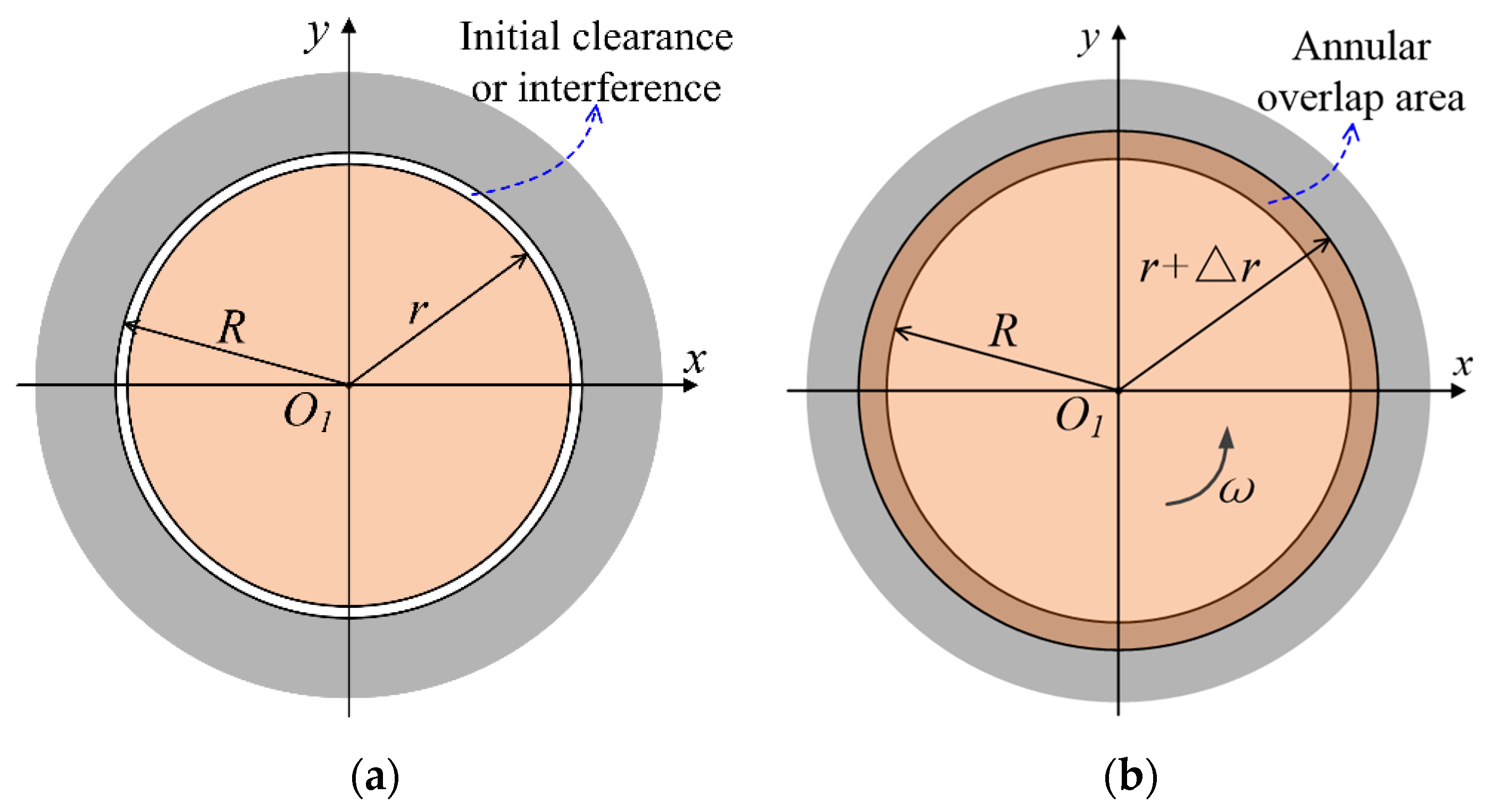
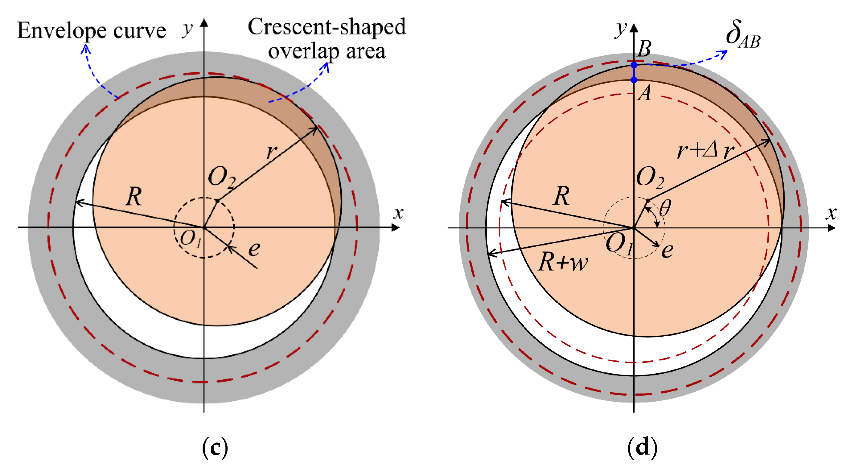
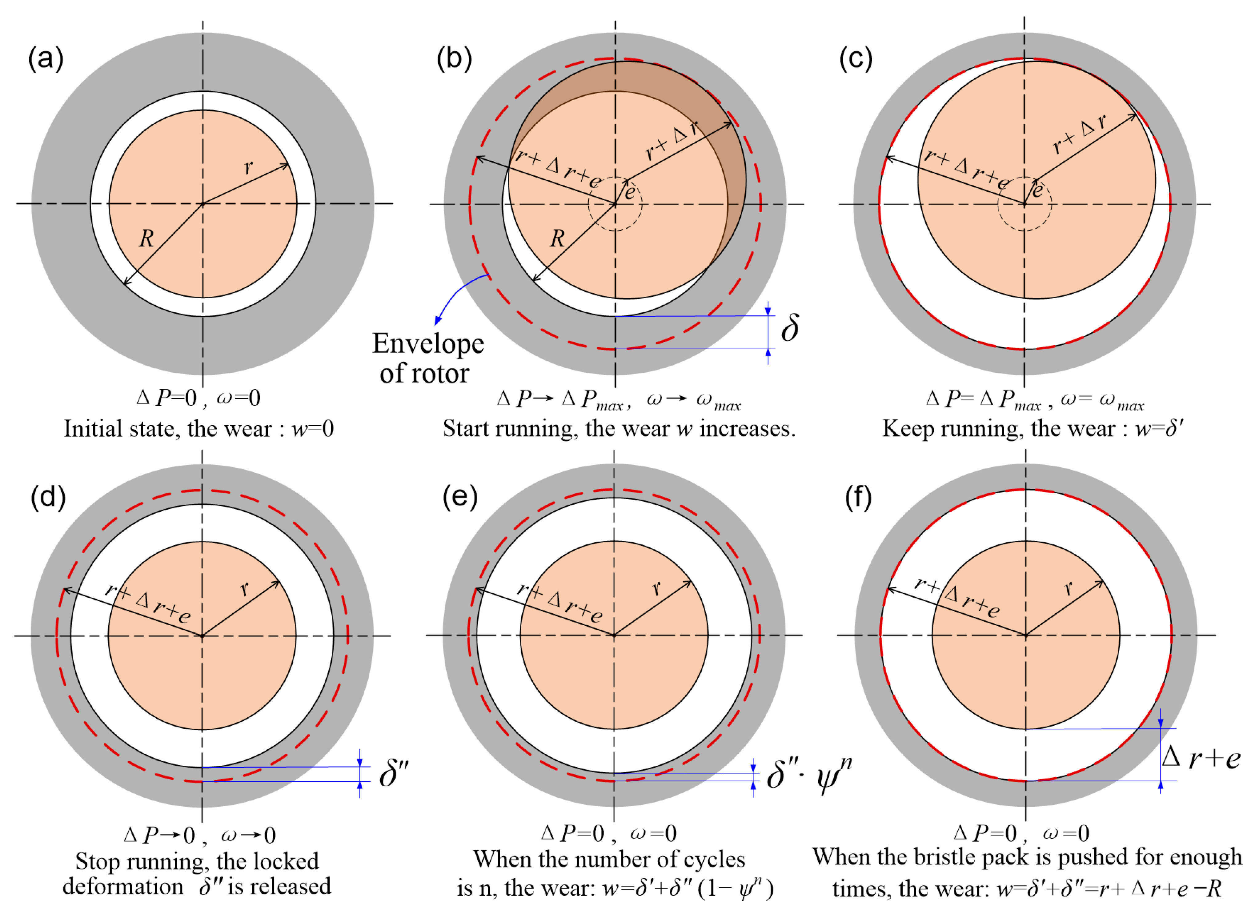
Firstly, the thermal deformation is temporally ignored, and only the centrifugal expansion of the rotor is considered. As shown in Figure 12a, is the initial inner radius of the brush ring bore, and the initial radius of the rotor. When the brush seal is running at a high rotating speed, a centrifugal expansion will appear on the rotor, and the rotor radius increases from to as shown in Figure 12b. An annular overlapping area will be formed between the rotor and bristle pack. The seal’s bore radius will also increase to . As shown in Figure 12c, a crescent-shaped overlap area may appear when the position of the rotor deviates from the axis of the bristle pack. The rotor position changes dynamically when the turbine machinery is running, and the rotor trajectory is closely related to the working state of the brush seal. In order to simplify the description of rotor-stator eccentricity, it is assumed that the rotor axis moves along a circular track with radius when the running state of the turbomachine is stable (Figure 12c). The trajectory center coincides with the axis of the brush ring, and then the seal bore radius will reach , which coincides with the rotor envelope. In Figure 12d, rotor-stator eccentricity and expansion act together, the wear rate of the brush seal is proportional to the area of overlap, and the seal bore radius will finally reach to .


Figure 12.
Wear behavior affected by eccentricity and radial deformation; (a) without eccentricity and radial deformation; (b) with radial deformation; (c) with eccentricity; (d) with eccentricity and radial deformation.
In Figure 12d, the radial interference at the y-axis can be written as:
Considering the radial interference , so radial deformation of the bristle at the y-axis can be written as follows:
The instantaneous wear rate of the bristle at the y-axis is directly proportional to at the y-axis, and the wear rate at other angular positions can be calculated in the same way. Generally, the rotor vibrates more than thousands of times during only one minute in turbomachinery. However, the wear process of brush seal has a relatively long-time process, which is far longer than the rotor vibration period. Therefore, a statistical description of the rotor position is enough for wear process analysis. The wear rate of the bristle pack depends on the average radial deformation during a rotation cycle, so variable in Equation (6) can be eliminated. The average of radial deformation can be written as:
In a previous analysis, it is considered that the center of the rotor trajectory coincides with the axis of the bristle pack, which leads to uniform wear on the bristle pack. However, the center of the rotor trajectory can be eccentric with the bristle pack, which may cause non-homogeneous wear on the bristle pack. This effect is ignored in this paper in order to avoid excessive complexity with the mathematical model. Actually, excessive eccentricity between the rotor and stator should be avoided during the initial assembly. Consequently, ignoring the eccentricity of the rotor trajectory in the mathematical model is reasonable in most cases.
Thermal deformation is not considered in the previous analysis. Since the brush seal often works in high-temperature gas or steam environment, the thermal deformation of the brush seal is noteworthy, including the rotor and the brush ring. If there are similar ambient temperatures and thermal expansion coefficients with the rotor and the brush ring, then their thermal deformation will offset each other approximately. On the contrary, when the thermal expansion coefficients or temperatures of the rotor and the brush ring are significantly different, the change of interference or clearance of the brush seal caused by thermal deformation cannot be ignored. In addition, friction heat exists at the rotor surface and the tip of the bristles. However, the temperature rise caused by friction heat is generally limited to the vicinity of the tribo-pairs, and the influence of friction heat will be weakened by heat conduction, forced convection, wear and the hysteresis effect. Therefore, the thermal deformation caused by friction can be ignored generally compared with that caused by ambient temperature.
Variable represents the increase of rotor radius caused by centrifugal force, variable represents the increase of rotor radius due to temperature rising, and represents the increase of brush ring radius due to temperature rising. It is reasonable to replace the variable to in order to add the thermal deformation into the wear model. Considering the thermal deformation, Equation (7) can be modified as follows:
3.3. Relationship between Wear Rate and Radial Interference
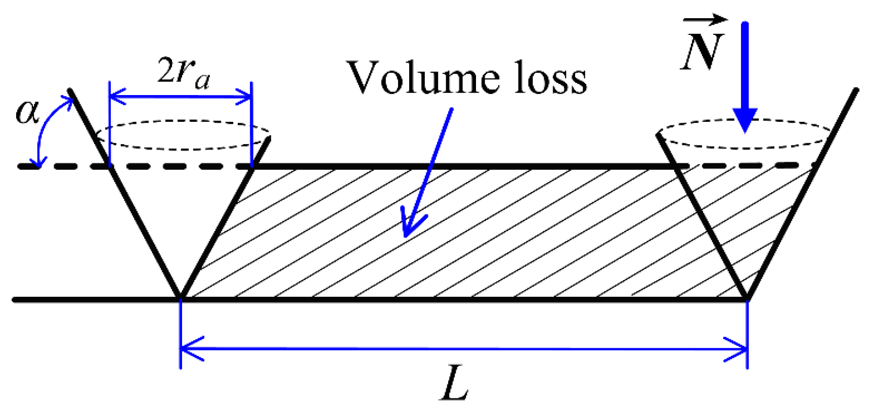
Due to the wear-resistant coating sprayed on the rotor surface, the wear of the bristle pack is much faster than the rotor. For example, the wear volume of the rotor observed in reference [8] is only about 10% of that of the bristle pack. Consequently, the wear of the rotor is ignored in this paper. Archard equation based on adhesive wear has been applied to brush seal wear modeling by some researchers [4,15]. However, more and more researchers judged that the wear mechanism between bristles and rotor is mainly abrasive [3,7,16,17], and this is due to the high hardness of the wear-resistant coating sprayed on the rotor surface. According to the wear mechanism of abrasive wear shown in Figure 13, the expression of wear volume should be , the relationship between material hardness and normal contact load is . The Rabinowicz equation is suitable for abrasive wear, expressed as follows:
where is the wear volume; is the angle of a rough peak simplified as a cone; is a weighted average of the values of all the individual cones; is the normal contact load; is the sliding distance; is sliding speed; is the time interval; is the hardness of the softer surface; and is the wear coefficient of bristles which can be measured by experiments. Although the mechanisms of abrasive and adhesive wear are different, the Rabinowicz equation of abrasive wear and the Archard equation of adhesive wear share similar formulas. In Equation (9), and are determined by properties of tribo-pair; is related to the sliding velocity; and the normal contact load can be expressed as a function of radial displacement according to Equation (4).

Figure 13.
Schematic of Rabinovich model for abrasive wear [18].
The following relationship exists for each bristle based on geometric relations.
The differential equation about can be obtained according to Equations (9) and (10):
Combining Equations (4), (8) and (11) to obtain differential Equation (12) as follows:
where is a coefficient which is determined by geometric and material parameters of brush seal and named wear rate factor in this paper, its expression is as follows:
where represents the wear volume in unit sliding distance under unit load according to Equation (9), Fan Jinjin [8] measured the wear rate of tribo-pair using friction and wear testing machine for brush seal, is equivalent to the variable “” in Fan Jinjin’s paper. In Equation (13), parameters , , and are determined by the geometrical structure of the brush seal, is Young’s modulus of the brush bristle, refers to the coefficient of friction.
In Equation (12), is the function to be solved, is the time interval. Due to the complexity of expression for , the analytical solution of cannot be given. However, if the rotor-stator eccentricity is ignored, and , , and other parameters remain constant, Equation (12) could be simplified as follows:
where is the maximum value of radius wear, and . As a first-order linear differential equation with constant coefficients, the analytical solution of Equation (12) can be easily obtained, and the solution is
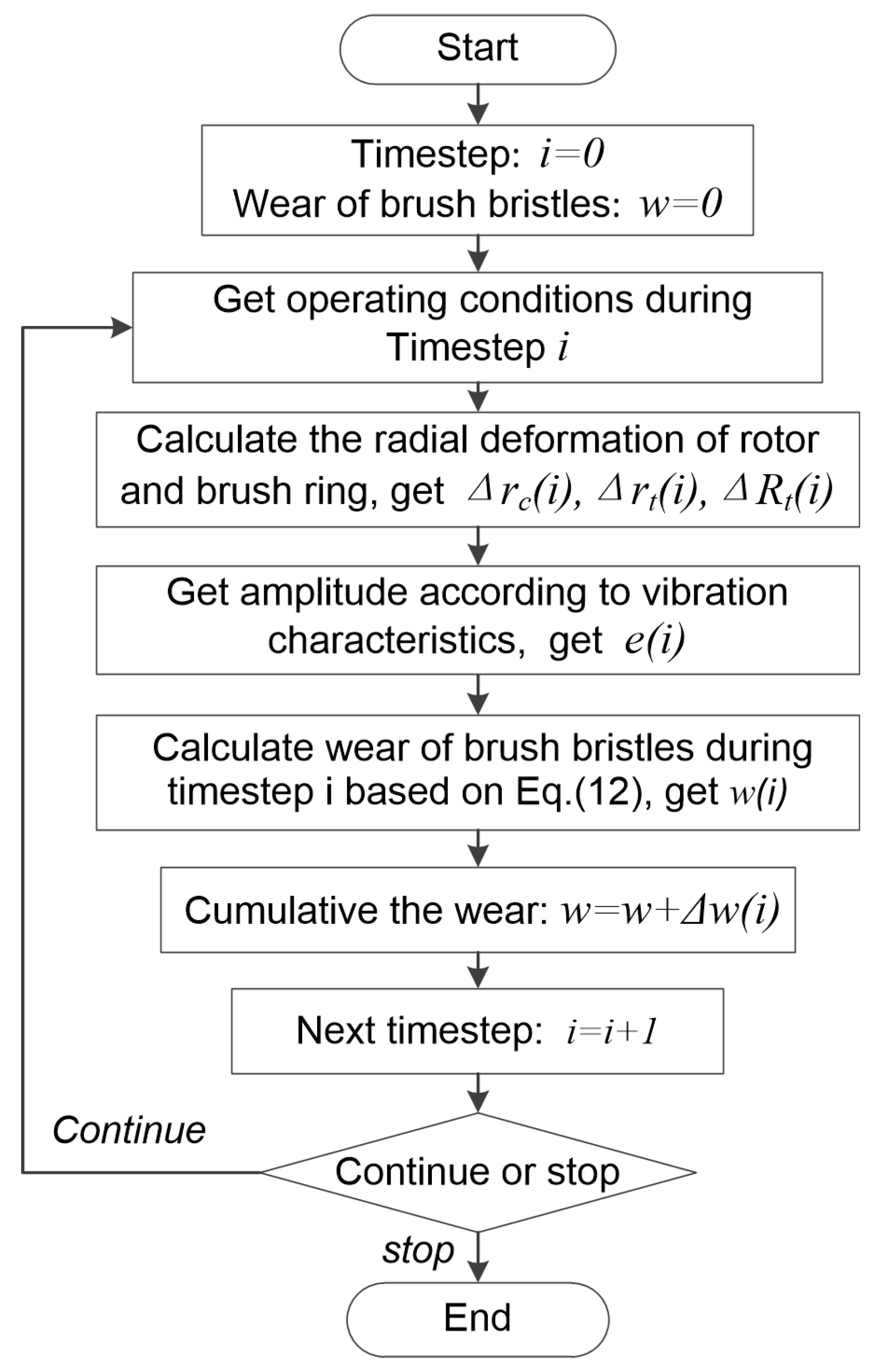
Equation (15) is similar to the analytical solution in reference [8]. However, the analytical solution will not be available when the eccentricity cannot be ignored or the rotating speed changes frequently. In this case, a numerical calculation method can be used to obtain the solution for Equation (12). The value of radius wear can be obtained by writing a program based on the flow diagram shown in Figure 14.

Figure 14.
Calculation program of bristle pack wearing.
3.4. Effect of Hysteresis
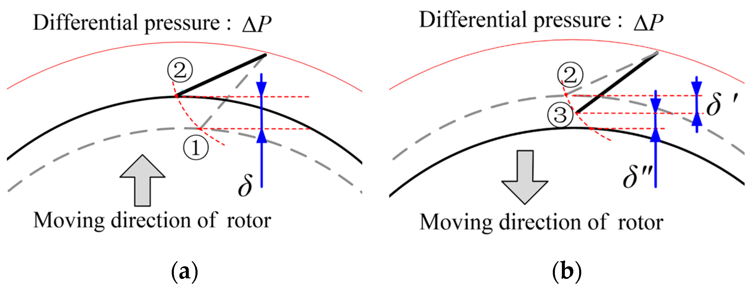
Due to friction on the cylindrical surface of bristles caused by pressure difference, the backward defection deformation of the bristle pack will not disappear immediately when the bristle pack is out of contact with the rotor. Moreover, the backward defection of the bristle pack will be maintained until the pressure difference decreases. The hysteresis effect increases the clearance between the bristle pack and the rotor and also affects the wear process at the same time. Zhao H and Stango RJ used the word “locked” to describe the hysteresis phenomenon of brush seals [19], which expressed this behavior intuitively and vividly.
As shown in Figure 15a, there is a radial displacement with the bristle tip after being pushed by the rotor. However, the bristle cannot rebound sufficiently when there is a pressure difference acting on the bristle pack after the rotor leaves away from the bristle tip. As shown in Figure 15b, represents the radial deformation that has rebound back, and represents the radial deformation being “locked” due to the hysteresis effect. The “locked” radial deformation is positively correlated with pressure difference; the value of is equal to zero when the pressure difference disappears. Obviously, there is a relationship as follows:

Figure 15.
Mechanism of hysteresis effect: (a) Bristles pushed by rotor; (b) Rotor disengages from bristles.
Due to the hysteresis effect, the wear behavior of the brush seal becomes more complicated. The wear process is not only determined by the rotor movement but also closely related to the variation of pressure difference.
As shown in Equation (16), the radial deformation of the bristle pack can be divided into and , and these two parts could be analyzed separately. For the wear caused by the rebounding radial deformation , the wear model established in Section 3.3 is still applicable; it is necessary to replace to and deduct the locked radial deformation from the radial interference . The average value of rebounding radial deformation is:
Accordingly, the differential equation of wear rate is:
As the wear increases, the rebounding radial deformation will decrease to zero first, and only the locked radial deformation remains, and the wear pattern will be different from that described in Section 3.2 after this time. The wear behavior will stop when the bristle tips are “locked” at a position with backward flection by the pressure difference. However, once the pressure difference drops, the “locked” deformation of the bristle pack may release immediately, which makes subsequent contact and wear unavoidable. When the turbomachinery restarts and reaches a high speed again, the pressure difference of the brush seal will also experience a rising process generally. In this process, the brush bristles will be pushed to the backward deflection position by the rotor and be “locked” again; the wear behavior only exists when the bristle pack is being pushed. A similar wear phenomenon may also occur when the rotating speed of turbomachinery experiences a falling and rising. The locked radial deformation will decrease gradually with the number of times increasing that the bristle pack has been pushed due to wear increasing. Figure 16 shows the wear process described above. The initial state is shown in Figure 16a. After running a for a period of time, the rebounding radial deformation will be sufficiently worn, as shown in Figure 16b,c. Due to the hysteresis effect, the wear will increase with the number of working cycles or times of bristle pack being pushed instead of running time. Figure 16d shows the initial value of the locked radial deformation. Moreover, as shown in Figure 16e, there is a relationship between radius wear and the variable :
where the wear ratio is a constant less than 1. And the integer is the number of working cycles or the number of times the bristle pack has been pushed. In Figure 16f, the wear will reach the maximum value when the value of is large enough.

Figure 16.
Wear process considering hysteresis effect.
3.5. Stiffening Effect and Blow-Down Effect
The “stiffening effect” is also related to the friction on the cylindrical surface. Contrary to the hysteresis effect, the stiffening effect acts on the process of the bristle pack being pushed away by the rotor and significantly increases the contact force between the bristle pack and the rotor. The bristle tip force increased by approximately five times at a difference of 300 kPa pressure than the unpressurized state in Duran’s experimental research [20]. The stiffening effect increases the friction between the bristles and the rotor when the bristle pack is pushed by the rotor. Therefore, the influence of the stiffening effect on wear behaviors can be reflected in the wear ratio .
The blow-down effect refers to the phenomenon that the brush bristles bend toward the rotor surface under the force of airflow, and the clearance between rotor and bristle pack will decrease under this effect. So, there are opposite effects with the blow-down and the hysteresis. When there is a pressure difference with the brush seal, the blow-down and the hysteresis act on the bristle pack at the same time, it can be considered that the hysteresis has overcome the blow-down. In this respect, it is not necessary to consider the blow-down individually. Generally, the effects of blow-down and hysteresis will be strengthened synchronously as the pressure difference increases, so it is reasonable to consider the blow-down and hysteresis together. However, the hysteresis effect depends on the pressure difference, and the blow-down effect depends on the airflow. The strength of airflow is not only determined by the pressure difference but also affected by the leakage clearance, which should be noted in some cases. In this paper, the blow-down effect will not be modeled separately in order to avoid the excessive complexity of the wear model.
4. Comparison between Experiment Results and Mathematic Model
4.1. Clearance Variation Analysis
According to the test results shown in Section 2, the leakage did not increase monotonously with the test time, and there was a sealing performance recovery phenomenon related to the hysteresis effect during the test. According to Figure 10, the maximum leakage rates occurred at Condition-B and A2 of Stage-3 and Stage-4. The bristle pack was pushed away by the rotor due to centrifugal expansion and vibration increase at 11,190 r/min, and then the deformation of the bristle pack was maintained even if the rotation speed dropped to 4660 r/min or zero. Based on the measured values of centrifugal expansion and vibration amplitude shown in Table 5, the clearance radius between the bristle pack and rotor at Condition-B and A2 of test Stage-3 and 4 can be calculated as follows:
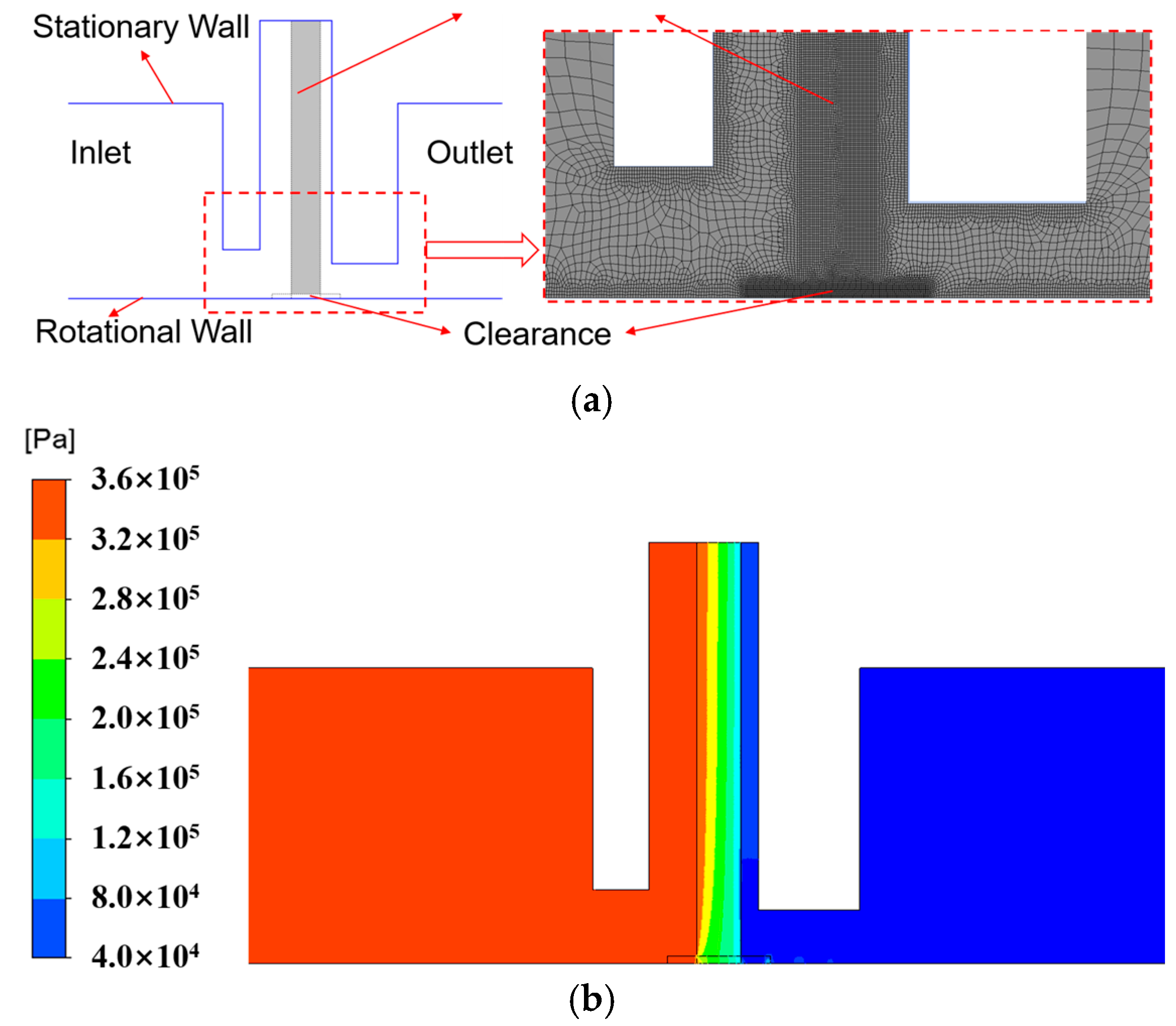
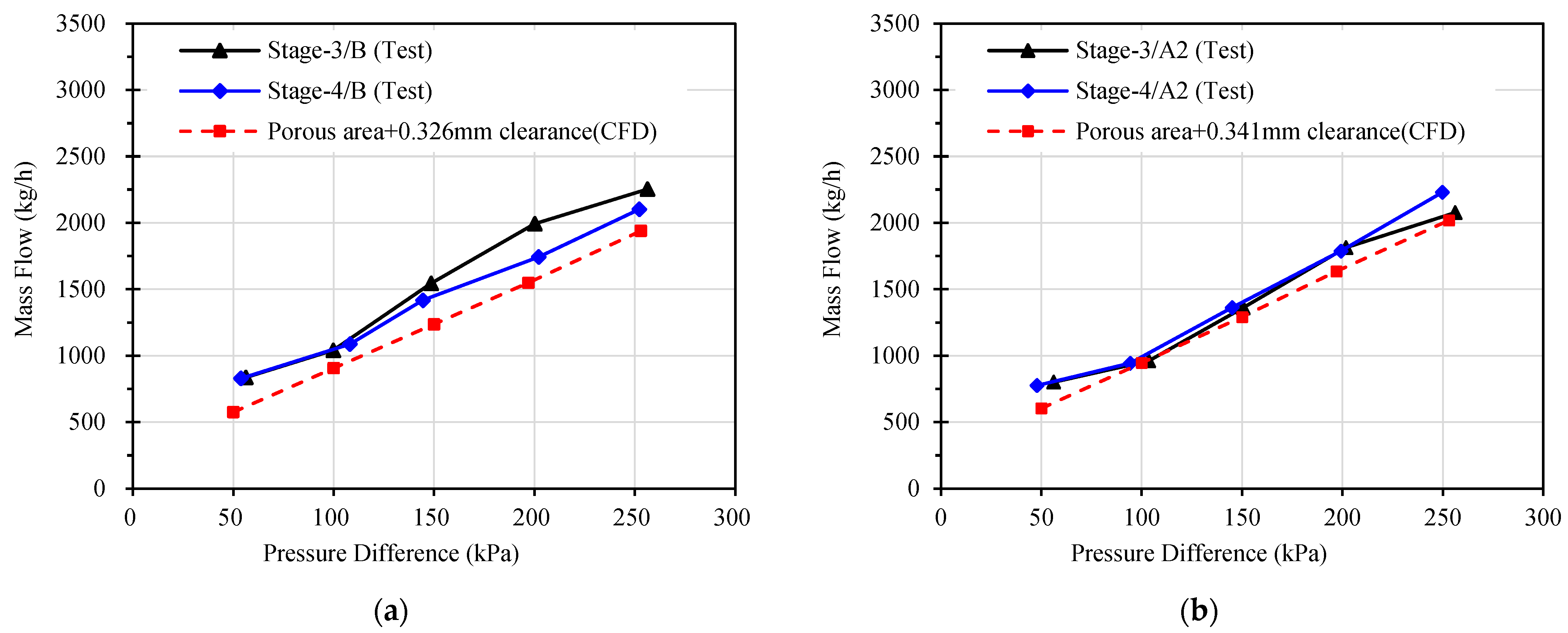
Based on the clearance values above, the leakage rates at different rotating speeds can be calculated by numerical simulation work. The porous medium model and a three-dimensional model are the two main solutions for the flow simulation of the brush seal. The porous media model is more widely used in engineering for its less computing and higher efficiency. A two-dimensional axisymmetric geometric model is used to describe the fluid domain. Figure 17a shows the boundary conditions and mesh of the established CFD model, the brush bristles are equivalent to a porous area, and there is a clearance between the porous zone and the rotor surface in the CFD model. Coefficients of inertial resistances and viscous resistances of the porous area are taken from reference [21]. The pressure values in the CFD model are given based on the measured values. The speed of the rotational wall is set as values in Table 4, and so is the air temperature. In addition, the ideal gas model was used to describe the air properties, and the renormalization group (RNG) k-ε turbulence model was selected to solve the established CFD model. Figure 17b is a pressure distribution result, in which the clearance is set to 0.326 mm, the inlet pressure is 348 kPa, the outlet pressure is 48 kPa, and the pressure difference is 300 kPa. Figure 18 shows the simulation results and test values of leakage rates, and it can be seen that the simulation results are consistent with the test values. From the above analyses, it is reasonable and necessary to consider the rotor eccentricity, radial deformation, and the hysteresis effect induced by them when evaluating leakage clearances of brush seals.

Figure 17.
Flow simulation of brush seal: (a) Boundary conditions and mesh; (b) Pressure distribution.

Figure 18.
Comparison between simulation results and test values: (a) Condition-B of Stage-3 and Stage-4; (b) Condition-A2 of Stage-3 and Stage-4.
4.2. Wear Behavior during the Test
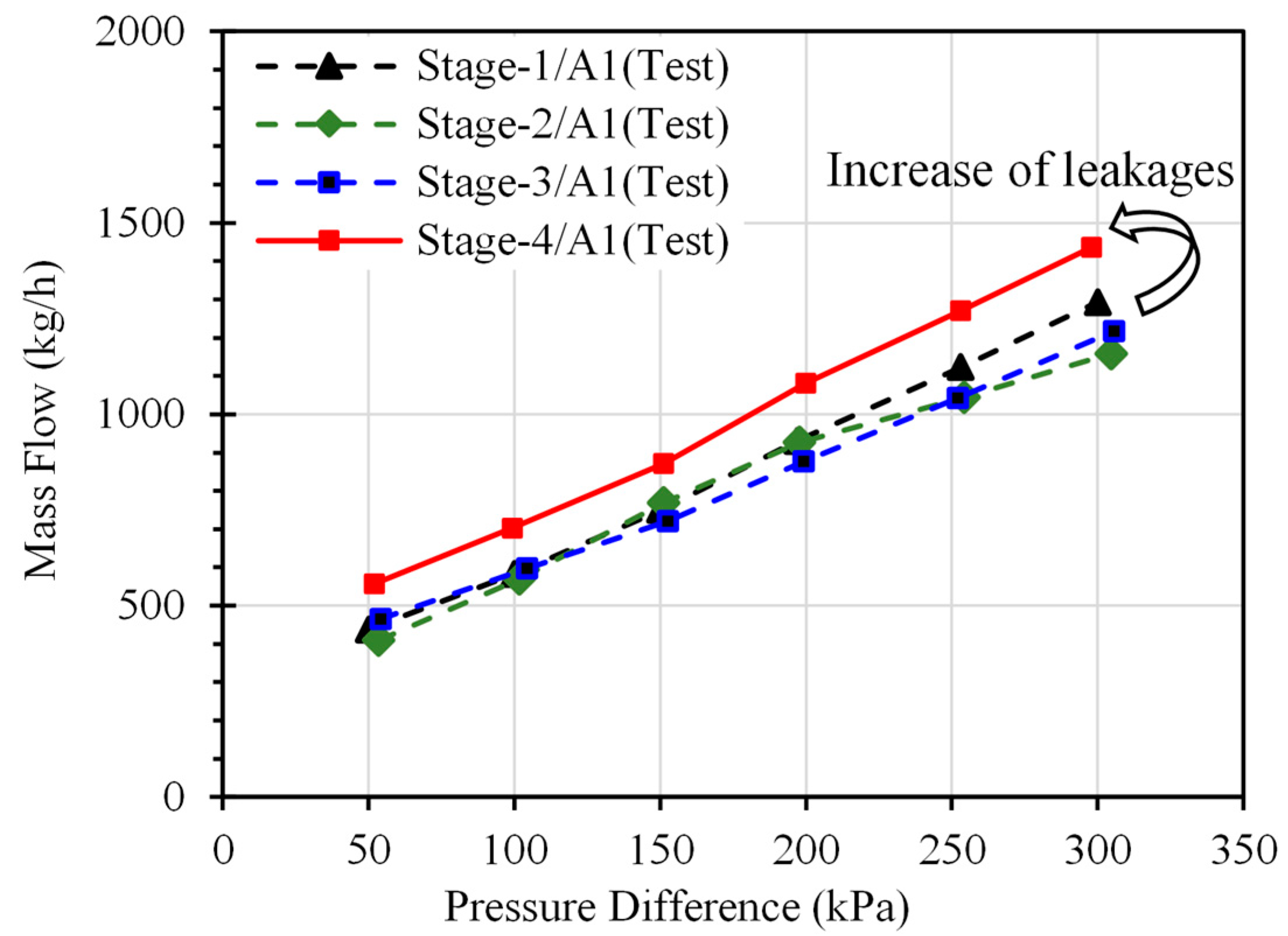
As analyzed above, the variation of leakage clearance during the test was not only affected by the wear behavior but was also significantly affected by the hysteresis effect. Moreover, the accuracy of the inner hole diameter measured by the measuring projector was not ideal, as shown in Section 2.2. Fortunately, the influence of hysteresis was eliminated at Condition-A1 of each test stage because the rotor rotation had not started yet, and there was no deflection deformation with the bristle pack. The leakage curves of Condition-A1 in the four test stages are listed in Figure 19. It can be seen that there is a small increase in the leakage rates of Stage-4/A1 compared with the first three stages, and the increase in leakage rates is 150 kg/h, approximately. Based on simulation analysis, the leakage increase shown in Figure 19 is equivalent to a 0.04 mm radius clearance increase.

Figure 19.
Leakage curves of Condition-A1.
In Kirk’s research [6], it can be seen that the wear process was completed approximately after dozens of working cycles. In the experimental research shown in Section 2, although the total running time of the four stages was 22 h, the running state remained unchanged during each stage. Before Stage-4/A1, the brush bristles were pushed away conspicuously only once when the rotating speed was rising to 11,190 r/min in Stage-3. Therefore, the wear during the bristles being pushed is ignored below. In addition, Dine et al. [22] studied the hysteresis effect quantitatively and provided the hysteresis test results with , , and seal housing offset. The results showed that seals had a very small recovery after a small offset but an 80–90% recovery after a large offset. According to Dine’s test results, the locked deformation is provided as (0.254 mm) in the following.
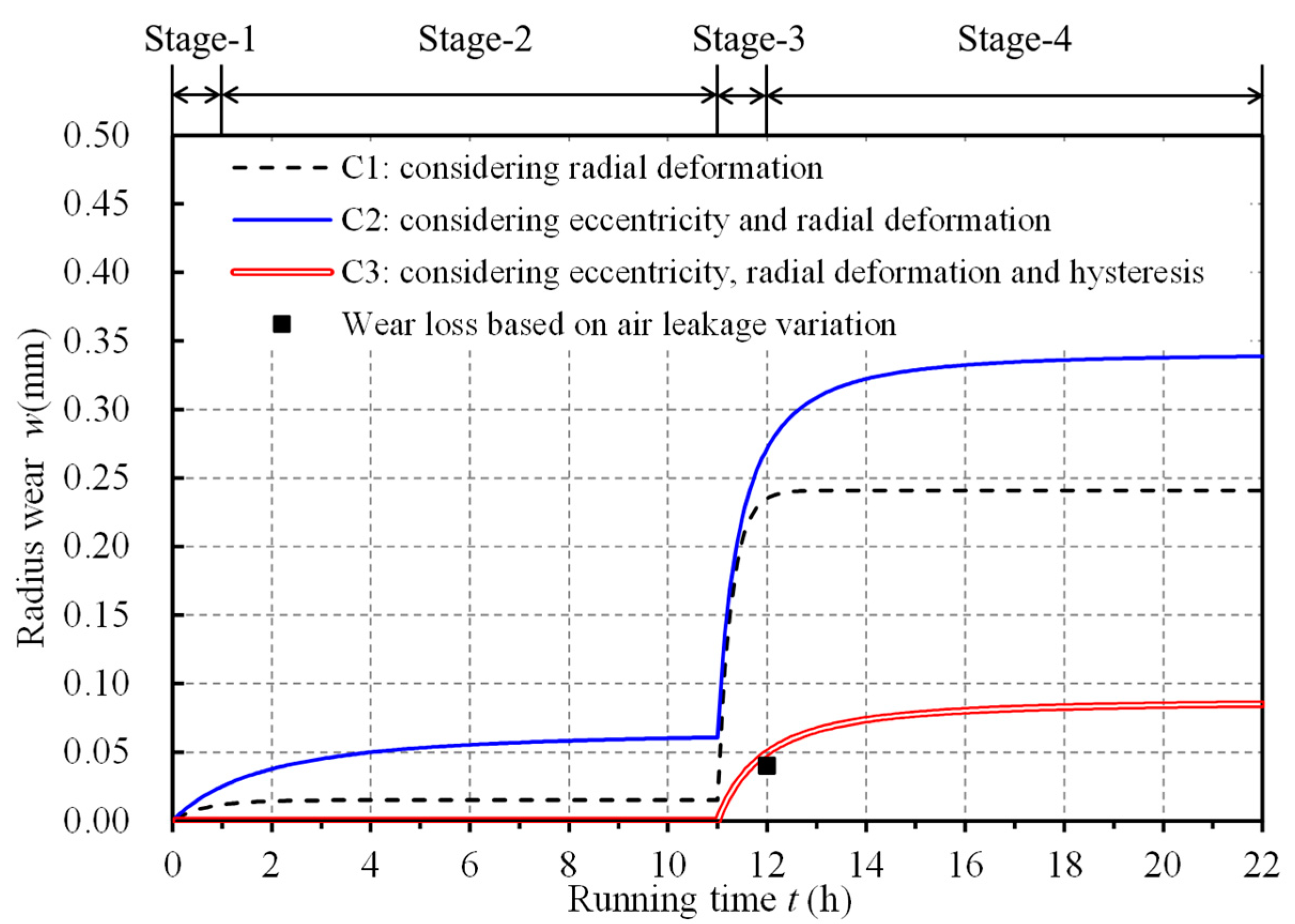
Based on the wear model established in Section 3, wear curves of the tested brush seals could be obtained by writing calculation programs. The obtained wear curve was different when different factors were considered. In Figure 20, rotor eccentricity and hysteresis effect were ignored in the wear curve C1, and only rotor deformation was considered. Both rotor deformation and eccentricity were considered in wear curve C2, but the hysteresis effect is still ignored. Influences of eccentricity, radial deformation, and hysteresis effect were considered simultaneously in wear curve C3. In the calculation programs, the initial diameter of the rotor and bristle bore were both taken as , the value of was taken as mm3/N·m based on reference [8], Young’s modulus of bristles was 210 GPa, the friction coefficient was 0.3, and the wear rate factor was calculated as . The rotor-stator eccentricity and radial deformation were set as Table 5 in each test stage, and the locked deformation was 0.254 mm, as mentioned earlier.

Figure 20.
Wear curves obtained by programming.
The 0.04 mm radius wear at the 12th hour (Stage-4/A1) is represented in Figure 20 as an experimental value, the corresponding radius wear on wear curve C3 is 0.05 mm, so there is an error of 0.01 mm or approximately 20%. In contrast, the errors of radius wear exceed 0.2 mm in curves C1 and C2 due to ignoring the hysteresis effect. The test work in this paper is one validation instance which prominently showed the influence of hysteresis. The wear model established in Section 3 contains multiple factors. It is meaningful to design and execute more validation tests with different operating conditions and brush seal structural parameters.
5. Conclusions
This paper gives a detailed introduction to a brush seal test. The test results evidently show that rotor-stator eccentricity and radial deformation significantly affect the wear behavior and leakage performance. Furthermore, the effects of eccentricity and radial deformation on the wear behavior of brush seals have been systematically studied. The abrasive wear equation is adopted to describe the material loss of bristles, and a simplified description is used to express the rotor-stator eccentric behavior. To describe the effect of hysteresis on wear behavior, the deformation of the bristle pack is divided into the rebounding deformation and the locked deformation; these two deformation types correspond to different wear patterns. Finally, a brush seal wear model considering rotor-stator eccentricity and radial deformation is established, in which the hysteresis effect is especially represented. The air leakage variation in the test shows that there is a radius wear of 0.04 mm at the 12th hour. However, if the hysteresis effect is ignored, the calculated radius wear exceeds 0.24 mm at the 12th hour. Considering rotor eccentricity, radial deformation, and hysteresis effect comprehensively as the established model, the calculated radius wear decreases to 0.05 mm, which is close to the experiment value. The brush seal wear model established in this paper has better adaptability to various operating conditions and brush seal structural parameters.
Author Contributions
Conceptualization, Y.X. and Y.L.; methodology, Y.X., J.Z. and Y.L.; validation, Y.X., T.M. and L.K.; formal analysis, Y.X.; investigation, Y.X., T.M. and Y.L.; resources, T.M. and L.K.; data curation, Y.X., T.M. and L.K.; writing—original draft preparation, Y.X.; writing—review and editing, Y.X. and J.Z.; visualization, Y.X.; supervision, Y.L.; project administration, Y.L.; funding acquisition, Y.L. All authors have read and agreed to the published version of the manuscript.
Funding
This research was funded by the National Science and Technology Major Project of China (No. 2017-VII-0013-0110) and the Industry-University-Research Cooperation Project of AECC (No. HFZL2018CXY003-2).
Data Availability Statement
Data sharing not applicable.
Conflicts of Interest
The authors declare no conflict of interest.
Nomenclature
| radial interference of bristle tip [mm] | |
| displacement of bristle tip [mm] | |
| N | normal contact force between bristle tip and rotor [N] |
| f | frictional force between bristle tip and rotor [N] |
| blow-down force on brush bristle [N] | |
| friction force on cylindrical surface of bristle [N] | |
| F | resultant of normal contact force and frictional force [N] |
| component force perpendicular to bristle [N] | |
| component force along bristle [N] | |
| friction coefficient [-] | |
| r | initial rotor radius [mm] |
| increase of rotor radius [mm] | |
| increase of rotor radius caused by centrifugal force [mm] | |
| increase of rotor radius caused by thermal deformation [mm] | |
| R | initial bristle bore radius [mm] |
| increase of brush ring radius [mm] | |
| increase of brush ring radius caused by thermal deformation [mm] | |
| e | equivalent radius of rotor eccentricity [mm] |
| w | radius wear of bristle pack [mm] |
| angular position of rotor axis [rad] | |
| free length of bristle [mm] | |
| Young’s modulus [MPa] | |
| second moment of bristle section [mm4] | |
| bristle lay angle [°] | |
| diameter of bristles [mm] | |
| wear volume [mm3] | |
| wear coefficient [-] | |
| hardness of rotor surface [kN·mm−2] | |
| wear rate factor [mm−1] | |
| running time [s] | |
| sliding velocity [m·s−1] | |
| rotating speed [r/min] | |
| pressure difference [kPa] | |
| rebounding radial deformation [mm] | |
| locked radial deformation [mm] | |
| wear ratio [-] | |
| number of working cycles [-] | |
| radius clearance between bristle pack and rotor [mm] | |
| effective clearance of brush seal [mm] |
References
- Dinc, S.; Demiroglu, M.; Turnquist, N.; Mortzheim, J.; Goetze, G.; Maupin, J.; Hopkins, J.; Wolfe, C.; Florin, M. Fundamental Design Issues of Brush seals for Industrial Applications. J. Turbomach. 2002, 124, 293–300. [Google Scholar] [CrossRef]
- Ferguson, J.G. Brushes as high performance gas turbine seals. In Proceedings of the ASME International Gas Turbine & Aeroengine Congress, Amsterdam, The Netherlands, 6–9 June 1988. [Google Scholar] [CrossRef]
- Menendez, R.; Xia, J. Recent developments in brush seals for large industrial gas turbines. In Proceedings of the 36th AIAA/ASME/SAE/ASEE Joint Propulsion Conference and Exhibit, Las Vegas, NV, USA, 24–28 July 2000. [Google Scholar] [CrossRef]
- Ha, Y.; Ha, T.; Byun, J.; Lee, Y. Leakage effects due to bristle deflection and wear in hybrid brush seal of high-pressure steam turbine. Tribol. Int. 2020, 150, 106325. [Google Scholar] [CrossRef]
- Gail, A.; Beichl, S. MTU brush seal-Main features of an alternative design. In Proceedings of the 36th AIAA/ASME/SAE/ASEE Joint Propulsion Conference and Exhibit, Las Vegas, NV, USA, 24–28 July 2000. [Google Scholar] [CrossRef]
- Hildebrandt, M.; Munz, O.; Schwitzke, C.; Bauer, H.-J. Experimental study on the wear-in behaviour of brush seals. In Proceedings of the ASME Turbo Expo 2020: Turbomachinery Technical Conference and Exposition, Online, 21–25 September 2020. [Google Scholar] [CrossRef]
- Chupp, R.E.; Dowler, C.A. Performance characteristics of brush seals for limited-life engines. J. Eng. Gas Turbines Power 1993, 163, 390–396. [Google Scholar] [CrossRef]
- Sun, D.; Li, H.; Zhao, H.; Zhang, G.C.; Li, Y.; Feng, Y.Z. Numerical and experimental study of frictional thermal effects of brush seals. Acta Aeronaut. Et Astronaut. Sin. 2022, 43, 425973. [Google Scholar] [CrossRef]
- Sun, X.P. Experimental investigation of performance and durability of brush seal. Aeroengine 2002, 42, 37–41. [Google Scholar] [CrossRef]
- Fellenstein, J.; DellaCorte, C.; Moore, K.; Boyes, E. High temperature brush seal tuft testing of metallic bristles versus chrome carbide. In Proceedings of the 32nd AIAA/ASME/SAE/ASEE Joint Propulsion Conference and Exhibit, Lake Buena Vista, FL, USA, 1–3 July 1996. [Google Scholar] [CrossRef]
- Prior, R.; Short, J.; Basu, P. Brush seal wear model. In Proceedings of the 34th AIAA/ASME/SAE/ASEE Joint Propulsion Conference and Exhibit, Cleveland, OH, USA, 13–15 July 1998. [Google Scholar] [CrossRef]
- Kirk, T.; Bowsher, A.; Crudgington, P. Aspects of brush seal design. In Proceedings of the 51st AIAA/SAE/ASEE Joint Propulsion Conference, Orlando, FL, USA, 27–29 July 2015. [Google Scholar] [CrossRef]
- Fan, J.; Ji, H.; Wang, Q.; Hu, Y.; Kong, X. A combined theoretical and experimental study of wear model of brush seal. Tribol. Int. 2021, 154, 106696. [Google Scholar] [CrossRef]
- Demiroglu, M.; Gursoy, M.; Tichy, J.A. An investigation of tip force characteristics of brush seals. In Proceedings of the ASME Turbo Expo 2007: Power for Land, Sea and Air, Montreal, QC, Canada, 14–17 May 2007. [Google Scholar] [CrossRef]
- Dong, S.N.; Du, C.H.; Cui, Y.H.; Zhang, Y.C.; Ji, H.H. Unilateral wear characteristics of brush seal based on Archard model. J. Aerosp. Power 2020, 35, 1437–1446. [Google Scholar] [CrossRef]
- Raben, M.; Friedrichs, J.; Helmis, T.; Flegler, J. Brush seals used in steam environments—chronological wear development and the impact of different seal designs. J. Eng. Gas Turbines Power 2016, 138, 051901. [Google Scholar] [CrossRef]
- Thakare, M.; Mason, J.; Owen, A.; Gillespie, D.; Wilkinson, A.; Franceschini, G. Effect of sliding speed and counterface properties on the tribo-oxidation of brush seal material under dry sliding conditions. Tribol. Int. 2016, 96, 373–381. [Google Scholar] [CrossRef]
- Rabinowicz, E. Friction and Wear of Materials, 2nd ed.; John Wiley & Sons, Inc.: Hoboken, NJ, USA, 1995; p. 192. [Google Scholar] [CrossRef]
- Zhao, H.; Stango, R.J. Role of distributed interbristle friction force on brush seal hysteresis. J. Tribol. 2007, 129, 199–204. [Google Scholar] [CrossRef]
- Duran, E.T. Brush seal contact force theory and correlation with tests. Alex. Eng. J. 2021, 61, 2925–2938. [Google Scholar] [CrossRef]
- Dogu, Y. Investigation of brush seal flow characteristics using bulk porous medium approach. J. Eng. Gas Turbine Power. 2005, 127, 136–144. [Google Scholar] [CrossRef]
- Dinc, S.; Reluzco, G.; Turnquist, N.; Lawen, J.; Kerber, O.; Brunner, F.; Crum, G.; Stuck, A.; Cromer, R.; Marks, P.; et al. Brush seals in Industrial gas turbines-turbine section interstage sealing. In Proceedings of the 34th AIAA/ASME/SAE/ASEE Joint Propulsion Conference and Exhibit, Cleveland, OH, USA, 13–15 July 1998. [Google Scholar] [CrossRef]
Disclaimer/Publisher’s Note: The statements, opinions and data contained in all publications are solely those of the individual author(s) and contributor(s) and not of MDPI and/or the editor(s). MDPI and/or the editor(s) disclaim responsibility for any injury to people or property resulting from any ideas, methods, instructions or products referred to in the content. |
© 2023 by the authors. Licensee MDPI, Basel, Switzerland. This article is an open access article distributed under the terms and conditions of the Creative Commons Attribution (CC BY) license (https://creativecommons.org/licenses/by/4.0/).

