Article

Preparation of an Anodic Alumina-Supported Ni Catalyst and Development of a Catalytic Plate Reformer for the Steam Reforming of Methane

State Key Laboratory of Materials-Oriented Chemical Engineering, College of Chemical Engineering, Nanjing Tech University, 30 Puzhunan Road, Nanjing 211816, China
*
Authors to whom correspondence should be addressed.
Energies 2023, 16(8), 3426; https://doi.org/10.3390/en16083426
Submission received: 31 January 2023 / Revised: 4 April 2023 / Accepted: 10 April 2023 / Published: 13 April 2023

Abstract

:
A plate-type Al/Fe–Cr alloy/Al-clad substrate was used to prepare a sandwich-structured plate-type anodic alumina catalyst by anodization, post-modification treatment, and metal loading. The as-prepared plate-type catalyst was utilized in the design of a catalytic plate reactor for a methane steam reforming reaction, and a 3D model was developed to simulate the performance of tube-type and box-type reformers. The experimental results of the preparation of the clad materials showed that the hydrothermal treatment and subsequent high-temperature calcination transformed the amorphous skeletal alumina in the conventional anodic alumina layer into γ-alumina, and significantly increased its specific surface area. Simulation results showed that the temperature difference between the channel wall and the center of the gas phase of the thin-walled catalyst was only 30% of that of the particulate catalyst, indicating the potential advantages of the catalytic plate reactor in terms of heat transfer and energy saving. When the length-to-diameter ratio (or length-to-width ratio) of the reaction channel is small and the channel height is large, insufficient transverse mass transfer and backmixing are two major factors affecting reformer performance. For the tube-type channels, a length-to-diameter ratio of 10~35, and a diameter of 5~20 represent favorable choices. In contrast, for the box-type channel, the length-to-width ratio and the height should be set to 2~4 and 2~5 mm, respectively. Additionally, for box-type channels, the number of gas inlet ports has a significant effect on the reformer performance, and the distribution state provided by two inlet ports is close to the ideal distribution state.

Graphical Abstract

1. Introduction

Fuel cells have received increasing attention as a new energy conversion technology with a high energy utilization efficiency and low environmental impact [1,2,3]. Fuel cells, such as PEMFC, perform best with high-purity hydrogen as a fuel source; however, pure hydrogen may not be used as a fuel source in the near future due to technical and economic considerations related to its production and storage [4,5,6]. Due to its high availability and it having the highest hydrogen-to-carbon ratio, the steam reforming reaction of methane (SRM) is still the main route for hydrogen production from fuel cells today [7,8,9].
Since it was first described in 1868, a great deal of research has gone into the development of SRM reformers. For example, Rahimipetroudi et al. [10] introduced an on-site hydrogen refueling station using steam methane reforming, consisting of twelve reforming tubes, flue gas tubes, and one newly designed burner. A typical reformer consists of a multi-tubular fixed-bed reactor with tubes filled with nickel catalyst pellets and heated by a gas furnace outside the tubes. The operating temperature range is from 773 K at the inlet to 1073 K at the outlet, with pressures of 20~40 bar and S/C (steam to carbon) ratios of 2~4. Conventional reformers have tube wall thicknesses of 10~20 mm [11,12], resulting in significant radial temperature gradients that limit the reaction rate. For example, Upadhyay et al. [13] described a palladium membrane reactor for SMR with a length of 300 mm, a height of 25.4 mm, and a wall thickness of 13 mm. In addition, poor intraparticle diffusion has been reported to result in an effective coefficient of only 0.02~0.03 in industrial steam reformers [14].
To design a compact SMR reformer with higher energy conversion efficiency, many improvements have been proposed, such as using fluidized beds, membranes, CO2 absorbers, rapid quenching [15,16], or shaping the catalyst into four or more holes, wagon wheels, and other shapes. For example, Wang et al. [17] investigated the hydraulic, dispersion, heat/mass transfer packed beds with simple-cubic packing, body-centered cubic packing, and face-centered cubic packing forms. However, these did not contribute much to the improvement of energy conversion and reformer downsizing until the advent of a multifunctional reactor, in which the strong endothermic SRM reaction is coupled to the exothermic methane catalytic combustion reaction by indirect heat exchange in a spatially separated process [13,18]. The symbolic reactor of this approach is the catalytic plate reactor (CPR). They are manufactured from plate-type catalysts, which effectively short-circuit the heat transfer resistance between the reaction site and the heating medium. In addition, the thin-walled catalytic layer can significantly enhance mass transfer within the particles [19]. A similar CPR reformer was proposed in a recent article published in Science. Kevin et al. [20] reported that reactor walls coated with a catalytic layer have the potential to exploit the intimate contact between the heat source and the reaction site to drive the reaction closer to thermal equilibrium and improve selectivity and yield.
However, due to the smooth surface and high thermal expansion coefficient of the metal substrate, the wash coating layer prepared by the dip coating method tends to peel off from the metal substrate, especially under high temperature and high vapor concentration conditions. This has become one of the bottlenecks in the development of CPR reactors. Our group is attempting to use a self-growing film of a metal substrate as the catalytic support layer instead of the conventional coating layer, namely a porous anodic alumina (PAA) layer [21]. It is well known that anodization can convert the surface of aluminum plates or aluminum-clad plates into porous alumina layers. However, this unmodified PAA usually has a low specific surface area of 5~40 m2/g, making it difficult to meet the requirements of the catalyst support. Our previous study [21] found that hydrothermal treatment under mild conditions and subsequent calcination treatment above 400 °C could convert the amorphous skeletal alumina of the PAA layer into γ-alumina and significantly increase its specific surface area. An as-prepared plate-type catalyst support can be added into a supported catalyst using a simple wet impregnation method. Furthermore, its two sides can separately load different active metals to play different catalytic roles, such as SRM and methane combustion catalysts. For more than half a century, the adhesion of PAA film has been frequently verified in many fields, such as corrosion protection and metallic coloring (including the coloring of iPhone mobile phone shells, Apple Inc. in Cupertino, California, USA). In addition, in our previous study [21], a plate-type anodic alumina catalyst prepared using an Al/alloy/Al-clad plate was subjected to a thermal tolerance test of up to 4000 heating–cooling cycles (at 1073 K), and no peeling of the alumina layer from the substrate was observed.
The design of a catalytic plate reactor (CPR) mainly involves numerical study using the finite element method to solve models coupling mass transfer, momentum transfer, and heat transfer with chemical reactions [19,22,23,24,25]. The studies are mainly focused on the coupling of SRM and the methane combustion reaction, the effect of channel height and inlet conditions (S/C, inlet temperature, and space velocity), etc. However, the reaction kinetic parameters used are often theoretical parameters of conventional SRM catalysts cited from other journals, which may not be suitable for the current plate-type anodic alumina catalysts. For example, Pashchenko et al. [26] introduced a new method based on the thermal conductivity equation to determine the temperature distribution inside the catalyst particle. Furthermore, the reaction rates for the reaction element were determined according to an accepted study conducted by others.
In previous studies, the reaction kinetics have been derived from experimental data obtained using our anodic alumina-supported nickel catalyst. Moreover, the shapes of reformer channels in these studies have been mainly cubic (box-type reformer), while cylindrical (tube-type reformer) channels have been studied less often. Nevertheless, tube-type reformers have superiority in many aspects, such as being easier to seal and having no stagnant region. What is more, most of the current industrial reformers are tube-type, which means that research using a tube-type CPR can easily be applied to update the current industrial reformer. Therefore, the analysis of a tube-type reformer is essential. In this paper, both tube-type reformers and box-type reformers were studied in parallel, and a comprehensive comparison between tube-type reactors and box-type reactors was also made.
The increase in model dimensionality will make models significantly more complex and time-consuming, requiring more physical parameters and boundary conditions. To date, most computational investigations have been based on simple one-dimensional (1D) or two-dimensional (2D) models, which can increase the potential risk of large deviations in reactor design and optimization. In this work, we developed a three-dimensional (3D) model to investigate the effects of channel shape, channel height, and non-uniform feed on reformer performance.
As mentioned above, in this study, a sandwich-structured plate-type anodic alumina catalyst was innovatively prepared by anodization, post-modification treatment, and metal loading, and it was used in the design of a catalytic plate reactor for an SRM reaction. This plate-type catalyst is expected to solve the problem associated with the wash coating layer having a tendency to peel off of the metal substrate when it is prepared using the traditional dip coating method. Furthermore, a 3D model was developed to simulate the performance of the reformer to help reduce simulated deviations. In addition to the conventional box-type reformer, a more easily constructed and scaled-up tube-type reformer was designed and comparatively investigated.

2. Experimental

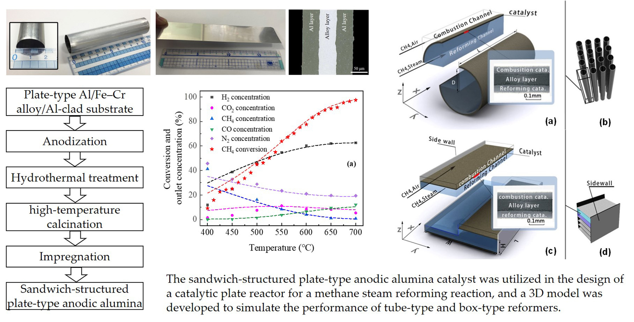
2.1. Preparation of Anodic Alumina Catalyst

The preparation of the anodic alumina support was carried out according to our previous research [21]. Prior to anodization, a commercial plate-type Al/Fe–Cr alloy/Al-clad (40/50/40 μm) substrate (Datong Steel Co., Ltd. in Nagoya, Japan) was heat treated in a muffle furnace at 550 °C for 12 h. The plate was then anodized in a 4.0 wt.% oxalic acid solution at a current density of 50 A/m2 for 8 h at a temperature of 20 °C to convert its surface Al layers into porous anodic alumina layers. The resulting plate was then immersed in deionized water at 85 °C for 2 h. The plate was dried and calcined in air at 500 °C for 3 h to obtain γ-alumina layers with a large specific surface area. A plate-type anodic alumina-supported Ni catalyst (18 wt.% Ni loading) was synthesized via a double impregnation method using the as-prepared anodic alumina support. The calcination temperature was 700 °C after the first impregnation and 500 °C after the second impregnation. During the two calcinating processes, the heating rate was 5 °C/min.

2.2. Characterization of Anodic Alumina Catalyst

Powder diffraction (XRD) was conducted using a Rigaku D/max-2500 diffractometer with Cu Kα radiation as the radioactive source. The morphology of different post-treated PAA materials was observed using a scanning electron microscope (SEM, JEOL JSM-5900LV). An ASAP 2020 analyzer was used to characterize the textural properties. The surface area and pore volume were calculated by the BET and BJH formulas.

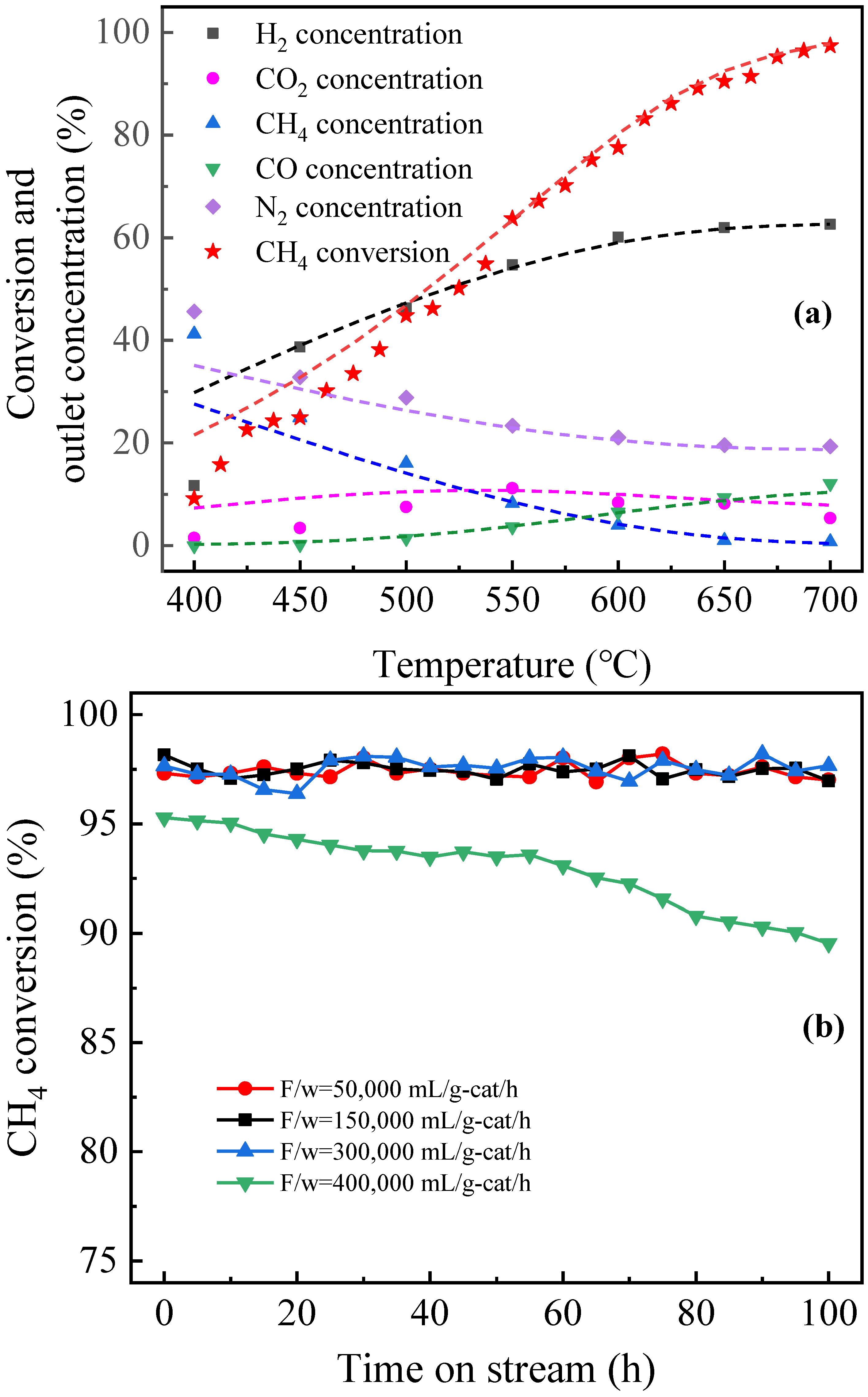
2.3. Steam Reforming of Methane

A plug-flow fixed-bed reactor was used to perform SRM activity tests and obtain kinetic data. The plate catalyst was cut into small pieces (~5 mm2), diluted with quartz sand, and loaded into the reactor. It is worth noting that for the kinetic data testing, the catalytic layer was scraped off the plate catalyst and tested in the powder state to avoid the effect of concentration gradients. The composition of the outlet gas was determined using on-line gas chromatography (GC-2014AT, Shimadzu Corp.). The reaction temperature was 723~973 K, the space velocity (F/w, defined as the inlet flow rate per amount of catalyst, excluding the Fe-Cr alloy layer) was 50,000~300,000 mL/g-cat/h, and the S/C ratio was 2~3. Prior to carrying out the SRM activity test, the catalyst was reduced at 700 °C (5 °C/min heating rate) in 50% H2/N2 flow.

3. Mathematical Model for the SMR Reformer

3.1. Reactor Schemas

Figure 1 shows a schematic diagram of the tube-type and box-type SRM reformer cells. In a tube-type or box-type reformer, the anodic alumina catalyst was formed into a tube or plate shape, respectively. The inner and outer layers of the sandwich structure of the anodic alumina catalyst were prepared to produce the SRM catalyst and methane combustion, respectively. The SRM reaction took place inside the tube-type reformer channel or inside the box-type reformer channel, while the methane combustion reaction took place outside. The plate-type catalyst itself was used to separate the different channels. The reactants of the combustion reaction and the reactants of the SRM reaction were introduced in a co-current mode. The co-current mode allowed for a self-sustaining operation in a wider range of flow regimes than the counterflow mode [22]. The reaction conditions and catalyst parameters are listed in Table 1. It is worth noting that no anodic alumina catalyst was placed on either side of the box channel.
To build a reformer, the box-type reformer cells could be scaled up by stacking and connecting them in parallel (Figure 1d). However, the arrangement of the reaction tubes in a tube-type reformer (Figure 1b) required more computational work, following the design of the reformer unit. This study focused on the design of the reformer unit.
It should be noted that the simulation of the combustion channel was not performed simultaneously in this study. The temperature distribution along the surface of the combustion catalyst was consistent with Figure 2, as required by our partners, and this temperature distribution was derived from a real industrial reformer.
The reformer was simplified under the following assumptions:
  • Operation was in steady state;
  • Gases were assumed to be ideal gases obeying the ideal gas law;
  • Chemical reaction took place only in the catalyst layer.
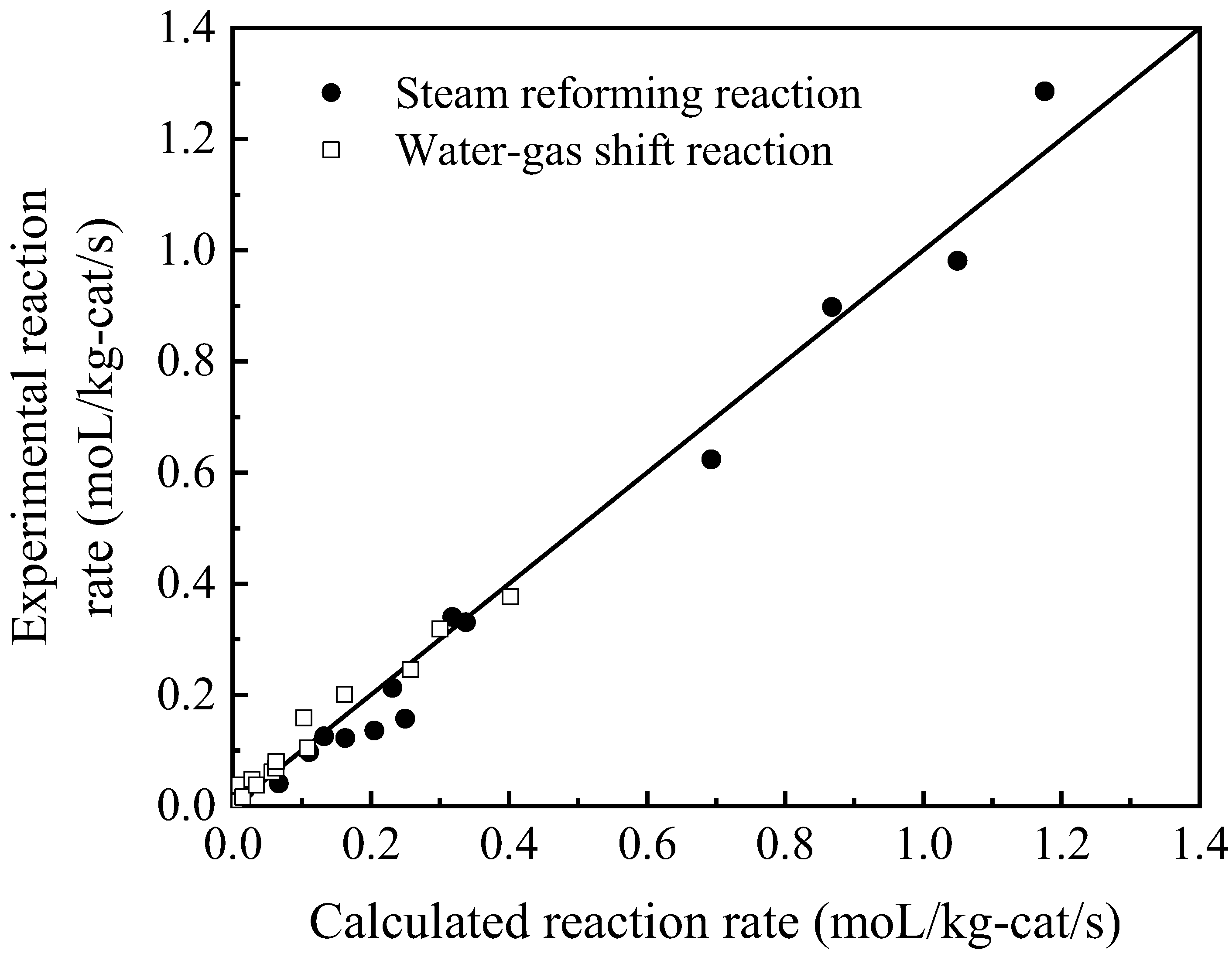
3.2. Kinetics Data

The main chemical reactions involved in the system studied were the SRM reaction ( C H 4 + H 2 O C O + 3 H 2   Δ H 0 298 0 = 206.2   kJ / mol ) and the water–gas shift (WGS) reaction ( C O + H 2 O C O 2 + H 2   Δ H 0 298 0 = 41.2   kJ / mol ).
Various kinetic rate expressions based on different mechanisms have been classified as elementary reaction kinetic equations [27,28] and global equations [29,30]. We found that the kinetic mechanism reported by Numaguchi and Kikuchi [31] better describes the SMR reaction process carried out over our catalyst. The equations are given below:
Steam reforming of methane: W 1 = k 1 ( p CH 4 p H 2 O p CO p H 2 3 / K 1 ) p CH 4 m 1 p H 2 O n 1
Water–gas shift reaction: W 2 = k 2 ( p CO p H 2 O p CO 2 p H 2 / K 2 ) p CH 4 m 2 p H 2 O n 2
  • where the equilibrium constant Km (m = 1 or 2) was calculated from thermodynamic data. The pre-exponential factor (A) and the activation energy (Ek) were estimated from experimental data using the least squares method.

3.3. Mathematical Model

The partial differential equations (PDEs) used in the model were described in compact vector form considering that the standard cartesian equation notation of a 3D model was too cumbersome. The system of PDEs is shown in the following paragraph. The reactant gas could not be treated as incompressible, because the gas density varied considerably during this reaction. The mass transfer equations were calculated based on the mass fraction to cover the effect of density, and a compressible formulation of continuity was used to calculate the momentum balance. Since this study involved only steady-state simulations, parameters such as the temperature and concentration of each reactant did not vary with time, meaning that the expression of the partial differential with respect to time could be neglected.

3.3.1. Gas Phase

Mass transfer [32]:
t ( ρ ω i ) + j ˙ i + ρ ( u ˙ ) ω i = R i
j i = ( p D i ω i + ρ ω i D i M n M n )
M n = ( i ω i M i ) 1
Conservation of mass [32]:
ρ t + ( ρ u ˙ ) = 0
Heat transfer [32]:
ρ C p T t + p C p u ˙ T = ( k T ) + Q
Navier–Stokes velocity equation [33]:
ρ ( u ˙ ) u ˙ = ( p + μ ( u ˙ + ( u ˙ ) T ) 2 3 μ ( u ˙ ) I ˙ ) + F
Compressible formulation of the continuity [33]:
ρ t + ( ρ u ˙ ) = 0

3.3.2. Catalyst Phase

Mass transfer: [34]
t ( ρ ω i ) + j ˙ i = R i j i = ( p D i ω i + ρ ω i D i M n M n ) M n = ( i ω i M i ) 1
Conservation of mass [34]:
ρ t + ( ρ u ˙ ) = 0
Heat transfer [34]:
ρ C p T t + p C p u ˙ T = ( k T ) + Q

3.3.3. Boundary Conditions

Inlet conditions [35]:
Velocity :   u ˙ = U 0 n ˙
Temperature :   T = T 0
Concentration : n ˙ N ˙ i = N 0 , j
Outlet condition [35]:
Pressure :   p = p 0
Convection-dominated heat and mass transfer at outlet boundaries
n ˙ ( k T ) = n ˙ ρ D i ω = 0
Wall conditions [35]:
u ˙ = n ˙ ( k T ) = n ˙ N ˙ j = 0

3.3.4. Symmetry

Velocity [36]:
u ˙ n ˙ = K ˙ ( K ˙ n ˙ ) n ˙ = 0 K ˙ = ( μ ( u ˙ + ( u ˙ ) T ] n ˙
Heat and mass transfer [36]:
n ˙ ( k T ) = n ˙ N ˙ j = 0     ( N o t e :   n ˙   i s   t h e   v e c t o r   p o i n t i n g   o u t   o f   t h e   d o m a i n )
Comsol multiphysics 4.2a from Comsol Inc., which supports 3D models and multiphysics analysis, was used in our work. The chemical reaction engineering module, the CFD module, and the heat transfer module were used to build and solve the reformer models.
In addition, the formulae for calculating the heat capacity, thermal conductivity, diffusion coefficient, diffusion in the catalyst layer, and other physical parameters used in the above model are detailed in the “Appendix A” section.

4. Results and Discussion

4.1. Preparation and Activity Test of an Anodic Alumina-Supported Ni Catalyst

The Al/Fe-Cr alloy/Al-clad substrate is a composite material with a sandwich structure of two layers of aluminum and one layer of alloy made by a thermal compression bonding technique (Figure 3). The clad substrate is heat treated at 550 °C for 12 h before anodizing. Our previous research [37] has shown that during heat treatment, a transition alloy layer of several microns forms between the Al and alloy layers due to element diffusion. It is this transition alloy layer that imparts a highly stable adhesion to the anodic alumina layer obtained by anodizing the clad substrate.
After anodization, the porous alumina layer is self-generated in situ on the surface aluminum, as shown in Figure 3. As a porous catalytic material, the structure and composition of the PAA layer have many advantages, such as: being oriented vertically and aligned with pore channels, which are conducive to the high dispersion of active ingredients; having mesopores or even large pores, which are conducive to reducing the mass transfer resistance of reactants; and having a pore size and film thickness that can be easily adjusted by changing the anodization parameters. However, the conventional PAA layer still has some problems. For example, the specific surface area of the PAA layer is only approximately 10 m2/g, which is far from the commercial alumina support. In addition, the alumina in the PAA layer is amorphous, and its reactivity is poor. To solve these problems, we used hydrothermal treatment to modify the PAA material.
Hydrothermal treatment (HTT) of anodic alumina is one of the more classic techniques in areas such as corrosion protection and coloring of metals, with applications ranging from window frames to electronics (e.g., coloring the metal case of an iPhone). When PAA materials are subjected to steam, hot water, or metal salt solutions, the skeletal alumina reacts with water to form hydrated alumina, accompanied by volume expansion. Hence, the hydrothermal treatment is often referred to as a pore-sealing treatment. In this study, hydrothermal treatment was used as a means to change the phase state of the skeletal alumina in PAA materials. To avoid strong pore sealing, a mild HTT condition was adopted, i.e., soaking in hot water at 85 °C for 2 h. The anodization conditions of the samples used were as follows: 4% oxalic acid (20 °C) for 8 h under a current density of 50 A/m2.
Figure 4 shows the XRD patterns of the PAA materials with different post-treatments. The skeletal alumina obtained after anodization was amorphous alumina (sample a), and calcination at 350 °C did not change its crystal structure (sample b). The diffraction peaks of the HTT-treated sample (sample c) were attributed to boehmite (AlOOH, PDF# 21-1307). That is, the hydrated alumina produced by the hydrothermal treatment was boehmite (AlOOH). The HTT-treated sample retained the AlOOH crystal structure after further calcination at 300 °C (sample d). When the calcination temperature after HTT reached 400 °C or higher, two broad peaks attributable to γ-alumina [16] were clearly detected near 45° and 67° (PDF# 29-0063). This indicated that AlOOH underwent a phase change to form r-alumina during calcination.
As is shown in Figure 5, the dense aluminum layer on the surface of the clad material was transformed into a porous alumina layer after anodization (Figure 5(a1)). These pores were parallel to each other and had a diameter of approximately 50 nm (Figure 5(a2) and Figure 6a). After the HTT treatment, the hydrated alumina generated by the reaction of amorphous alumina with hot water adhered to the main pore skeleton derived from anodization, and the smooth main pore walls became rough (Figure 5(b2)). Furthermore, a large number of fish-scale protrusions appeared on the sample surface (Figure 5(b1)). Since the reaction of amorphous alumina with water to form hydrated alumina is accompanied by volume expansion, the diameter of the main pore resulting from the HTT treatment shrank significantly. However, the swollen hydrated alumina did not completely block the main pore structure, and the main pore could still be clearly observed on the surface and cross-section of the PAA sample (Figure 5(b1,b2)). The BET results showed that the average pore size of the HTT-treated PAA layer decreased from 50 nm to 4.6 nm, and the specific surface area increased from 13 m2/g to 40 m2/g (Figure 6b). After the next calcination at 500 °C, the surface (Figure 5(c1)) and cross-section (Figure 5(c2)) of the sample were similar to those of the uncalcined sample. However, the roughness of the pore walls and the fish-scale protrusions on the surface were reduced. Meanwhile, as is shown in Figure 6c, the pore size distribution showed that a large number of pores of approximately 3.7 nm appeared after calcination, leading to a significant increase in the specific surface area to 180 m2/g. Combining the SEM and XRD results, we considered that the hydrated alumina attached to the main pore wall lost its bound water during calcination and was converted to γ-alumina. In addition, numerous fine pores appeared at the locations where the bound water was lost.
The amorphous skeletal alumina was transformed into γ-alumina by a mild HTT treatment without destroying the macro-integrated structure and micro-ordered pore structure of the PAA material. At the same time, the specific surface area of the PAA layer was dramatically increased, comparable to that of commercial alumina. The main pores formed by anodic oxidation were still present in the modified PAA layer (Figure 5(c2) and Figure 6c), and a large number of finer pores (3.7 nm, Figure 6c) appeared in the main pore walls. This binary pore structure was favorable for the catalytic reaction. The fine pores facilitated high dispersion of the active components and provided a large reaction surface. In addition, the main pores with relatively large pore sizes produced by anodic oxidation met the requirement for diffusion channels for the reactants.
In our previous study [21], the supported Pt catalyst prepared using this plate-type support was applied to the catalytic combustion reaction of toluene. It was found that this anodic alumina catalyst could achieve higher active metal dispersion and better activity compared with conventional alumina-supported Pt catalysts with a disordered pore structure. The improved activity was attributed to the binary pore structure. Similarly, in the relevant literature [38], Hong et al. used a PAA material shaped into a θ-ring to prepare a Pd-based catalyst for ethylanthraquinone hydrogenation. They reported that a Pd-based PAA catalyst exhibited higher productivity than a spherical Pd/Al2O3 catalyst due to the advantages in the mass and heat transfer and confinement effect of the cylindrical pores.
A plate-type anodic alumina-supported Ni catalyst (18 wt.% Ni loading) was synthesized via a double impregnation method using the as-prepared anodic alumina support. The anodic alumina catalyst was used for the SRM activity test and the result is shown in Figure 7a. The methane conversion was close to the thermodynamic equilibrium data when the temperature exceeded 450 °C, indicating the excellent activity of the catalyst. The deviations from the equilibrium data below 400 °C could be attributed to the lower reaction temperature. Similar to the methane conversion, the concentrations of each reactant (on a dry gas basis) were in general agreement with the thermodynamic equilibrium data. Among them, the CO2 concentration showed a trend of increasing and then decreasing, confirming the presence of both the SRM reaction and the water–gas shift reaction in this reaction system. The presence of more than 98% of the C element equilibrium indicated that it was reasonable to consider only the SRM reaction and the water–gas shift reaction in the current reaction system. Moreover, as is shown in Figure 7b, no catalyst deactivation was observed within 100 h when the catalyst was subjected to a durability test at 700 °C (F/w from 50,000 mL/g-cat/h to 300,000 mL/g-cat/h) for 100 h. Therefore, it is acceptable to consider the system as a steady-state operation. within this F/w range. However, in experimental tests, when the space velocity was further increased to 400,000 mL/g-cat/h, the catalyst started to deactivate gradually. This catalyst deactivation may have been related to an excessive inlet velocity, and the exact cause of this is being resolved.

4.2. Reaction Kinetics Data

When testing the kinetics data of the anodic alumina catalyst, the catalytic layer was scraped from the plate catalyst into the powder state to avoid the effect of concentration gradients. Figure 8 shows the comparison of experimental and calculated values of the SRM reaction rate and the water–gas transfer reaction rate on the anodic alumina catalyst. The calculated values of these two reaction rates were in good agreement with the experimental results, which means that the obtained rate parameters shown in Table 2 are quite reliable.
Here, m1 = −1, m2 = −2, n1 = −1, n2 = −2.

4.3. Development of Catalytic Plate Reformer

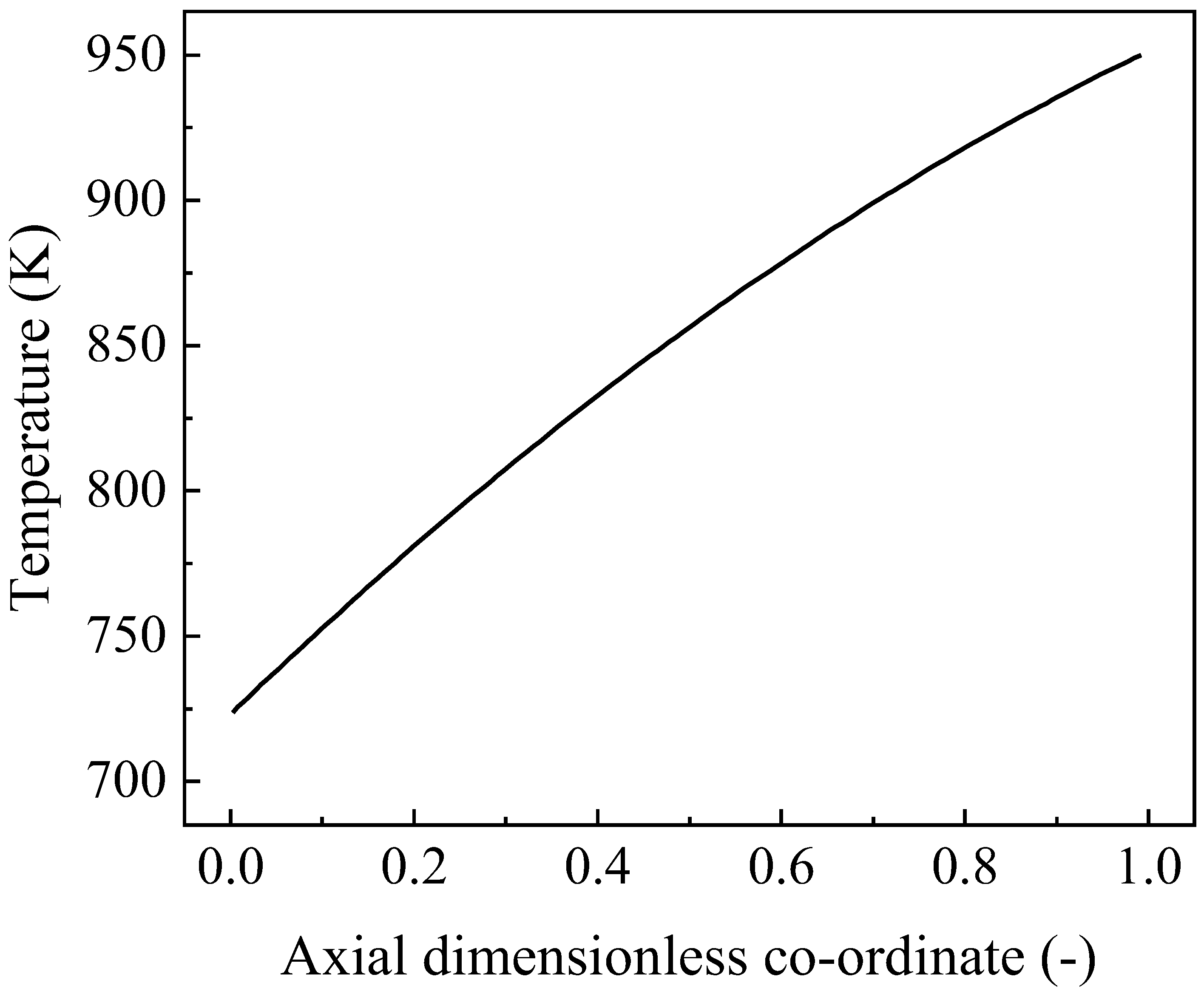
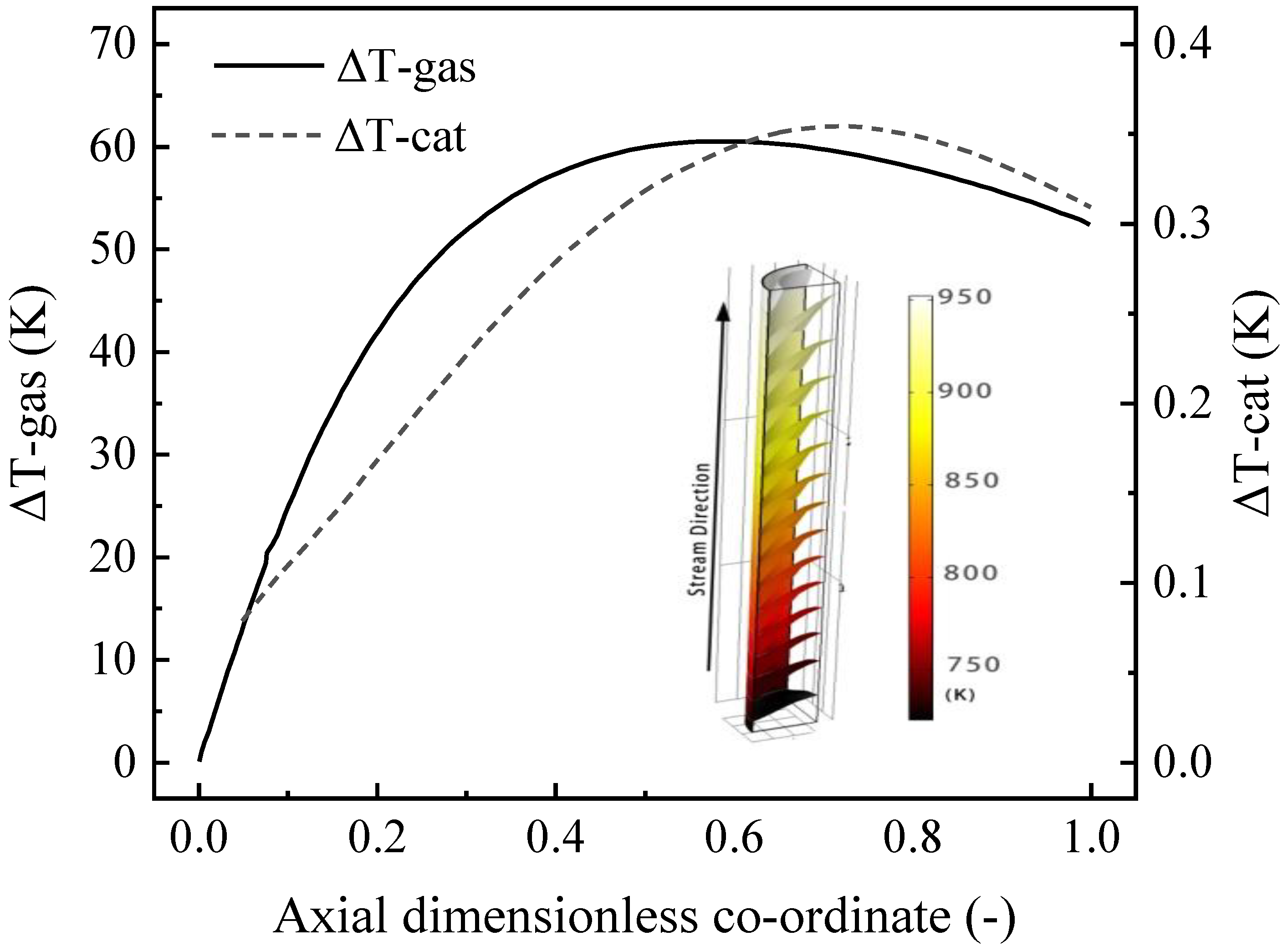
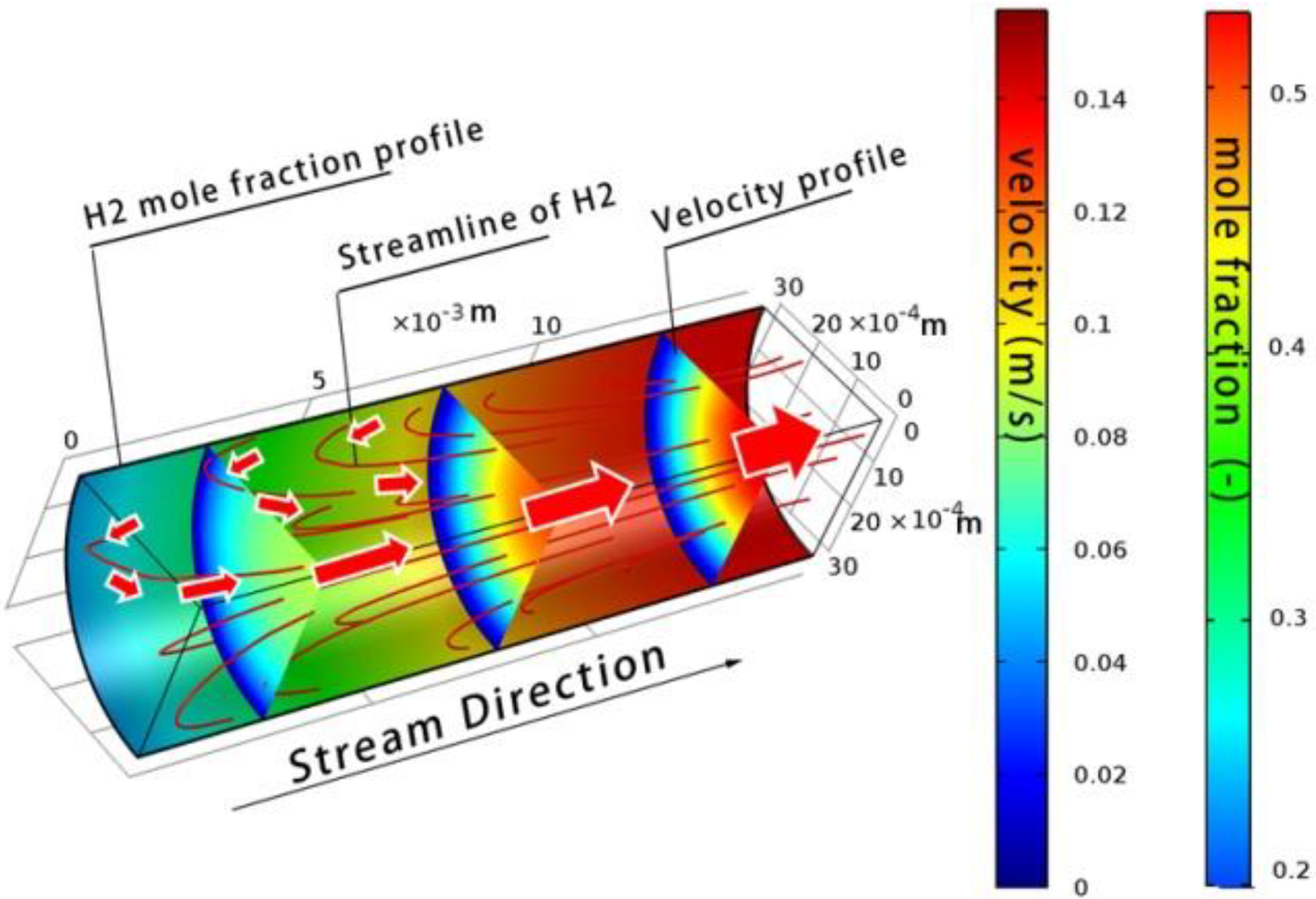
4.3.1. Distribution of Velocity and Temperature

In our 3D model, the effects of the two sidewalls of the box channel were taken into account. As is shown in Figure 9, the boundary effect of the sidewalls in the box-type reformer was obvious (especially when the channel width was small), resulting in an inhomogeneous velocity distribution along the y-axis. In contrast, in the relevant literature using the 2D model, it is generally assumed that the velocity along the y-axis is homogeneous since the 2D model has only a two-dimensional (x, z) velocity distribution. This obviously does not correspond with the real situation. Comparatively, the tube-type channel is ideal compared to the box-type channel.
Figure 10 shows the temperature distribution in the tube-type channel (diameter of 15 mm and length of 15 cm). The transverse temperature difference curve along the length of the reforming channel shows that the maximum temperature difference between the combustion catalyst (using the temperature data in Figure 2) and the reforming catalyst (ΔT-cat.) was less than 0.5 K. In contrast, the temperature difference between the reforming catalyst and the gas phase center (ΔT-gas) was less than 70 K. The literature [29] reported that in a conventional tubular reforming channel filled with catalyst pellets, the temperature difference between the tube wall and the gas phase center was approximately 250 K. The ΔT-gas, in the case of thin-walled catalysts, was only 30% that of pellet catalysts, indicating the potential advantages of CPR reactors in terms of heat transfer and energy savings. Similar results were observed for the box reformer and will not be repeated here.

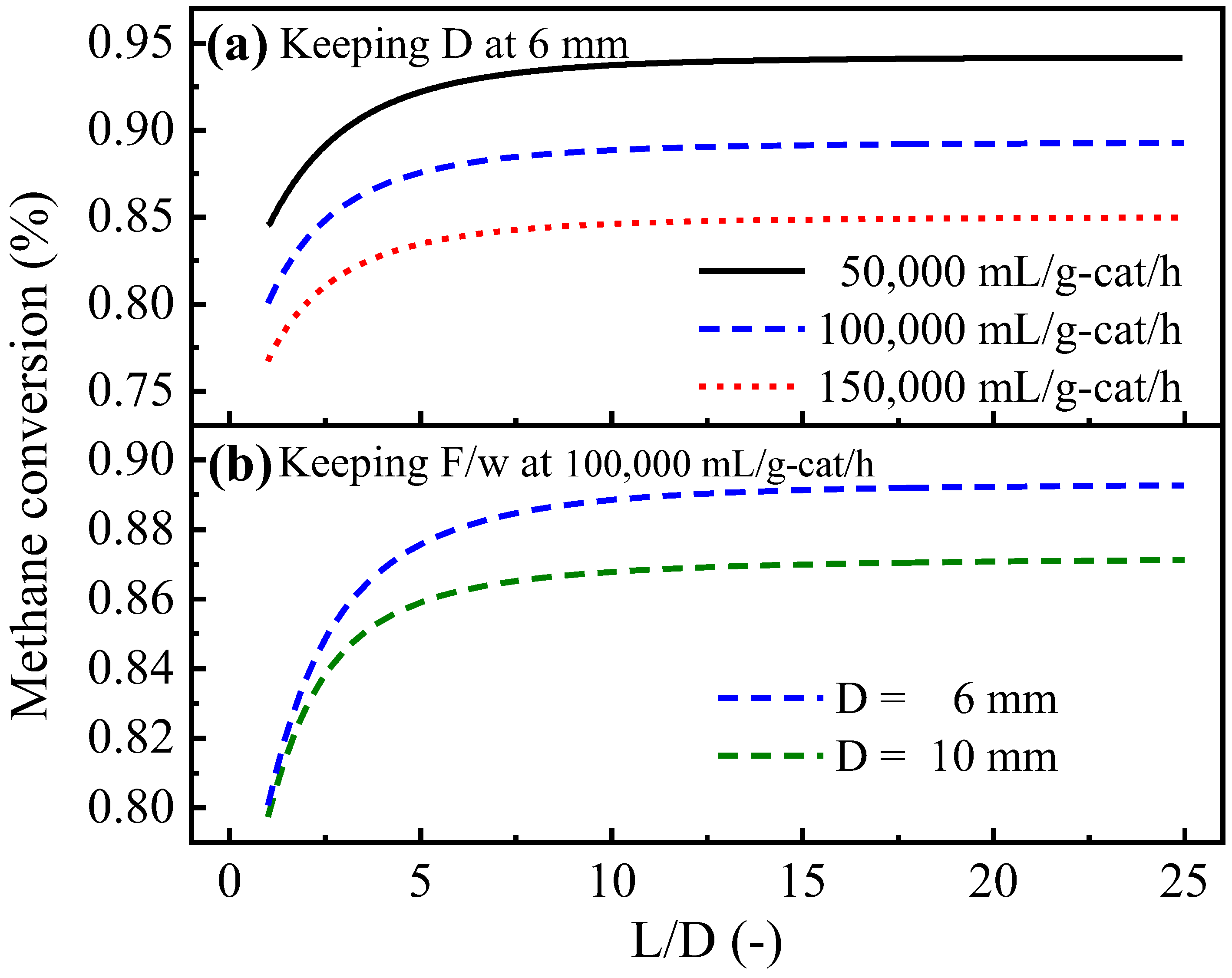
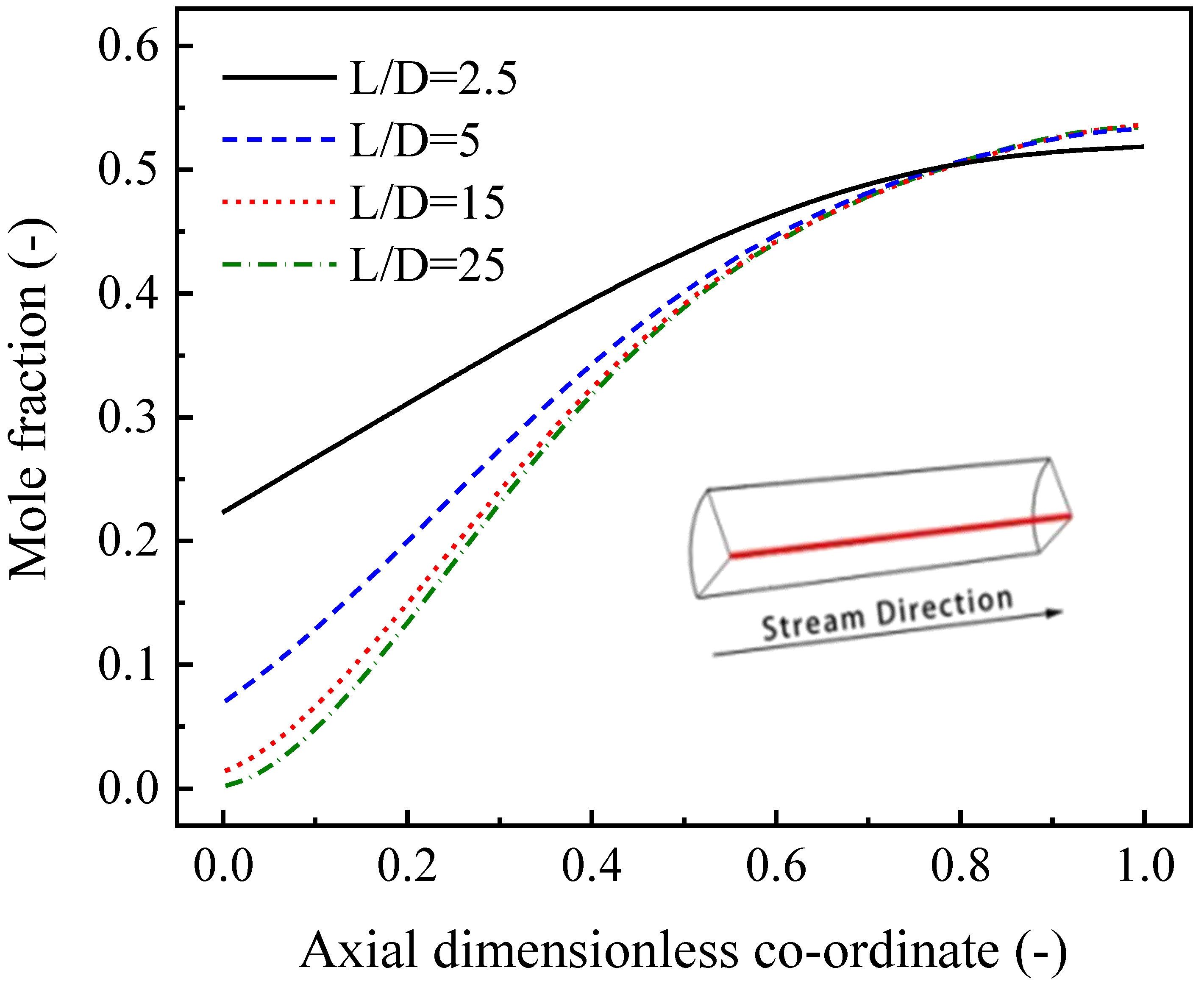
4.3.2. Effects of the L/D of Tube-Type Channels and the L/W of Box-Type Channels

The performance of plate-type CPR reformers is closely related to the design of the channels. In this study, the L/D (ratio of the length to the diameter of the channel, for tube-type reformers) or the L/W (ratio of the length to the width of the channel, for box-type reformers) was used as one of the main parameters to describe the channel shape. In the simulation cases, the influences of the L/D (Figure 11a) or L/W (Figure 11c) at different space velocities F/w were investigated by adjusting the channel length. The channel diameter D was kept at 6 mm for the tube-type channel (or 2 cm for the box-type channel). In addition, Figure 11b shows the effects of the L/D at different channel diameters of the tube-type channel, and Figure 11d shows the effects of the L/W at different channel heights of the box-type channel.
As shown in Figure 11, several of the cases calculated show roughly similar trends in variation. That is, for tube-type reformer channels, at different space velocities or different channel diameters, when the L/D exceeded 10, the methane conversion remained at a high level and decreased only slightly with a decreasing L/D. When the L/D was less than five, the methane conversion decreased rapidly with a decreasing L/D. When the L/D ranged from 5 to 10, the methane conversion decreased gradually with a decreasing L/D. Similarly, for box-type channels, at different space velocities or different channel heights, the range where the L/W was less than one corresponded to the region where the methane conversion changed rapidly. Furthermore, the range where the L/W was greater than two corresponded to the region where the methane conversion changed slightly.
To explain the aforementioned phenomenon, we selected a tube-type channel (F/w = 100,000 mL/g-cat/h, D = 6 mm) as an example to analyze the flow and reaction situation inside. The results showed that there was generally significant backmixing and insufficient transverse mass transfer in the regions where the methane conversion varied significantly. The result that backmixing also has a significant effect on methane conversion has not been suggested by other studies.

4.3.3. Analysis of Mass Transfer

The effect of the L/D on mass transfer can be analyzed by invoking the mass Fourier number, which is a function of axial coordinates and can be used to assess whether reactant molecules have enough time to reach the walls before leaving the reactor [39]. The mass Fourier number F0 was calculated according to the formula F 0 = τ s / τ d , where τ s is the local residual time and τ d is the transverse diffusion time. The local residual time τ s represents the time required for the fluid element at position (x, y, z) to leave the reactor and is calculated according to the equation τ s = ( L z ) / u s . The transverse diffusion time τ d is defined as the time required for the reactants to reach the wall by diffusion and is calculated according to the equation τ d = ( R ( x 2 + y 2 ) 0.5 ) 2 / D C H 4 . From the definition of the Fourier number, it can be concluded that at the (x, y, z) position, if F0 < 1 (or ln(F0) < 0), the reactant molecules do not have enough time to reach the catalyst before leaving the reactor, i.e., the transverse mass transfer is insufficient.
In a 2D model, the use of Fourier numbers to evaluate transverse mass transfer is to calculate F0 along the central axis of the channel. However, this can only provide a qualitative indication of where an insufficient transverse mass transfer occurs. In this study, we proposed a method that allowed the numerical evaluation of transverse mass transfer. To find the region of insufficient transverse mass transfer, the Fourier number of the entire 3D reforming channel was first calculated. However, considering the fact that the methane concentration varies downstream of the reformer, the volume percentage of the region of ln(F0) < 0 cannot accurately evaluate the region of insufficient transverse mass transfer. In this study, an invalid methane molecule ratio η was used, defined as the number of methane molecules counted in the region, where ln(F0) < 0 divided by the one counted in the entire channel. The larger the invalid methane molecule ratio η, the worse the transverse mass transfer. The invalid methane molecule ratio η can be calculated using the following equation:
η = C C H 4 f ( x , y , z ) C C H 4
f ( x , y , z ) = { 1 , ln ( F 0 ) < 0 ( x , y , z ) 0 , ln ( F 0 ) > 0 ( x , y , z )
The shorter the channel length, the shorter the local residence time. A larger diameter of the tube-type channel results in a lower transverse diffusion driving force (dC/dr) and a longer diffusion distance, i.e., an increased transverse diffusion time. Thus, the reduced L/D increases the ln(F0) < 0 region. Figure 12 shows an example of calculating the invalid methane molecule ratio η. When the L/D was less than five, the methane conversion decreased sharply, accompanied by a rapid increase in the invalid methane molecule ratio η. This indicated that the insufficient transverse mass transfer caused by a small L/D was the main reason for the poor performance of the reformer in this range of the L/D. In addition, as is shown in Figure 11, the methane conversion still gradually decreased with decreasing L/D in the L/D range of 5~10. This may be related to back mixing, in addition to the insufficient transverse mass transfer mentioned above.

4.3.4. Analysis of Backmixing

In addition to the insufficient transverse mass transfer, backmixing is a possible cause of undesirable flow behavior in the reformer. Considering the concentration distribution gradient, the diffusion direction of the resultants is towards the inlet, while convection brings them back to the outlet. In the gas phase, convection is much larger than diffusion. However, in the boundary layer (where the gas velocity is less than 0.02 m/s), convection can be neglected because the gas velocity is too low, leading to the backmixing of products such as hydrogen. The hydrogen streamline in Figure 13 clearly shows this backmixing phenomenon. Increased diameter reduced the intake velocity, which resulted in a thicker boundary layer. The decrease in length led to a proportional increase in the diffusion driving force (dC/dz) along the Z-axis. This clearly illustrates the backmixing phenomenon.
Figure 13 clearly shows that serious hydrogen backmixing occurred at an L/D of five in the tube-type channel, resulting in slower reaction rates for the SMR and WGS reactions in the first half of the channel. Similarly, hydrogen backmixing also occurred when the L/W of the box-type channel was less than two. The back-mixing in the box-type reformer tends to be more serious because the boundary layer exits along both sidewalls.
Figure 14 shows the molar fraction of hydrogen along the central axis of the tube-type channel. It is clear that the hydrogen concentration increased in the first half of the channel as the L/D decreased. Since the temperature near the inlet was quite low (~730 K), the SMR reaction rate was also slow. This means that the hydrogen should be brought close to the inlet by backmixing. By examining the L/D of the tube-type channel versus the H2 molar fraction near the inlet, we found that strong backmixing occurred when the L/D of the tube-type channel was less than 10. This result can be used to explain the gradual decrease in methane conversion with a decreasing L/D in the range of 5~10, as shown in Figure 10 and Figure 11. A similar result was observed when the L/W of the box channel was less than two.
It seems that the larger the L/D (or L/W), the better the reformer performance. However, in experimental tests, we found that an inlet velocity that is too fast, caused by a small L/D, often led to catalyst deactivation. The exact cause is under investigation. According to the available data, an L/D in the range of 10~35 for tube-type channels and an L/W in the range of 2~4 for box-type channels are favorable choices.

4.3.5. Effect of Height of Box-Type Channel

As is shown in Figure 11d, increasing the height of the box-type channel led to a decrease in methane conversion. As mentioned above, a larger channel height or channel diameter leads to longer transverse diffusion times, i.e., an increase in the region where ln(F0) < 0. By comparing the invalid methane molecule ratio η and methane conversion, it can be concluded that the decrease in methane conversion at a larger L/D or L/W is mainly caused by insufficient transverse mass transfer. Furthermore, the improvement in the mass transfer is less pronounced when the channel height is less than 5 mm for tube-type channels and less than 2 mm for box-type channels.
Although smaller channel heights result in better mass transfer, they are followed by excessively fast inlet velocities, which in turn, are related to the catalyst stability at this stage. In addition, reactors with small channel heights are more difficult to fabricate. At the present stage, we consider a box-type channel height of 2~5 mm, or a tube-type channel diameter of 5~20 mm to be a more appropriate choice.

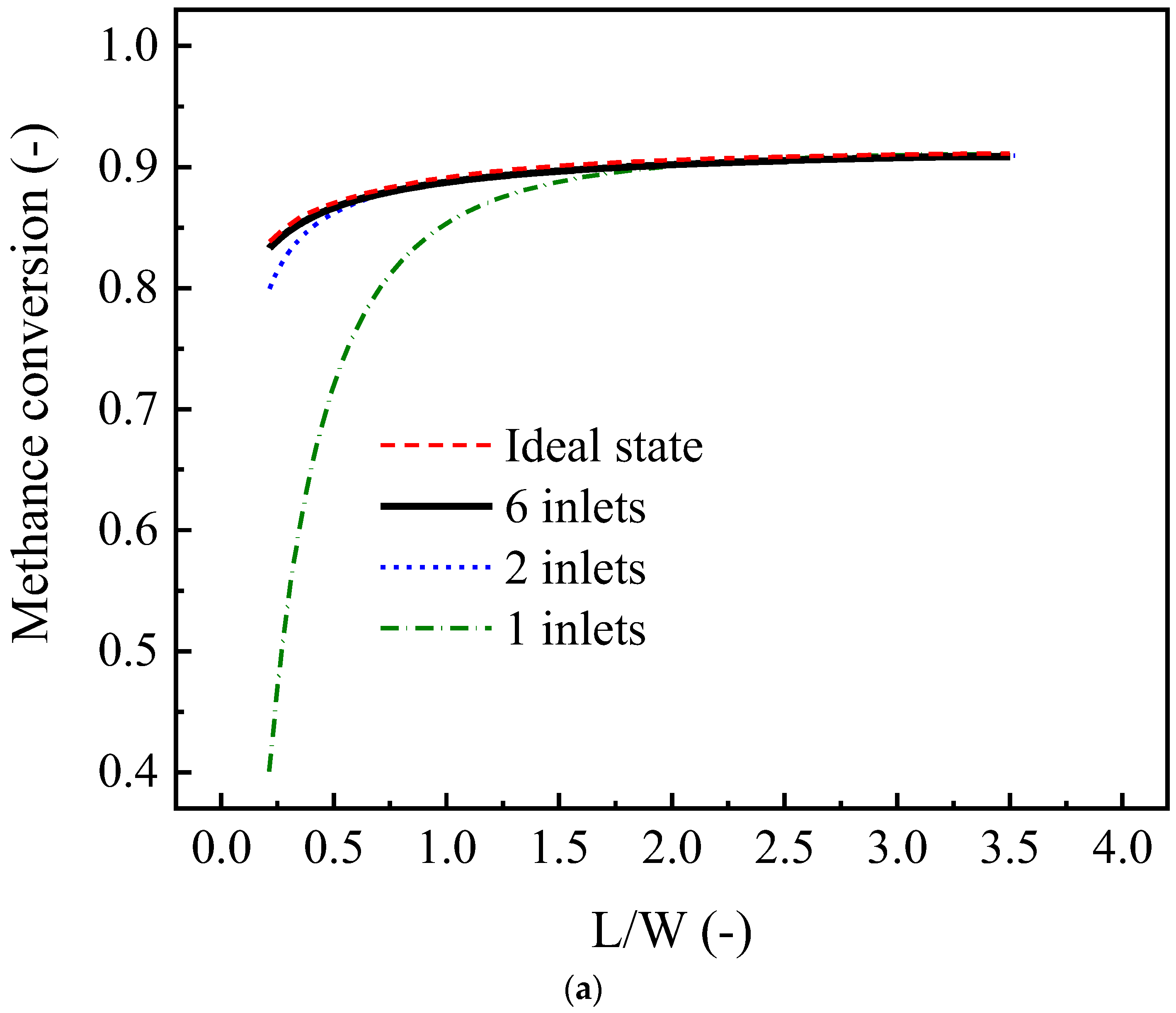
4.3.6. Effect of Number of Inlet Ports in a Box-Type Channel

One of the differences between box-type and tube-type channels is that the former does not easily achieve the desired distribution of the inlet flow in the absence of a distributor. This section discusses the effect of the number of inlet ports in the box-type channel. Each inlet port is set as a 2 mm diameter tube, the inlet ports are evenly distributed along the centerline of the reactor cross-section, and the flow in the inlet tubes is a well-developed laminar flow.
As is shown in Figure 15, the effect of the number of inlet ports on the reformer performance is clear, and this effect becomes more significant with a decreasing L/W (Figure 15a) or increasing H (Figure 15b). Under the current calculation conditions, the distribution state provided by one inlet port is far from the ideal distribution state, the case of two inlet ports is close to the ideal distribution state, and the distribution state almost overlaps with the ideal state when the number of inlet ports is increased to six. When the box-type channel has only one inlet, the L/W must be greater than two and H must be less than 3 mm to eliminate the effect of inhomogeneous inlet distribution. However, in the case of two inlets, an L/W greater than 0.5 and H less than 7 mm are sufficient. Although the use of a large L/W and a small H can suppress the effect of inhomogeneous inlet distribution to some extent, it may cause the risk of catalyst deactivation as described above, and the number of inlet ports in a box-type reformer should be at least two.
In the case of a single inlet port, the undesirable inlet gas distribution state leads to poor reformer performance, due to insufficient transverse mass transfer and severe backmixing. As is shown in Figure 16a, the gas velocity profile indicates that the inlet feed is poorly distributed in the reactor, creating a large stagnant region. The inhomogeneous distribution of the methane concentration along the Y-axis (Figure 16c) indicates insufficient transverse mass transfer. The flux streamline (Figure 16b) shows that a large vortex is formed in the case of a single inlet port, resulting in serious backmixing and a low reaction rate.

4.3.7. Comparison of Tube-Type and Box-Type Channels

The different structures of the two reformers make them very different in terms of performance and manufacturing difficulties. The tube-type channel consists of a cylindrical catalyst, which tends to produce a homogeneous distribution of the gas flow near the inlet and inside the channel. In contrast, the box-type channel has no catalyst on either side wall and has four right angles inside the rectangular channel, resulting in an inhomogeneous flow distribution and even a stagnant region. This tends to make its performance lower than that of the tube-type channels. It should also be noted that the reaction rate distribution along the Y-axis in the box-type channel is not inhomogeneous due to the concentration gradient (Figure 16c). This inhomogeneity increases the difficulty of achieving the desired coupling between the reforming reaction and the combustion reaction on the other side of the plate-type catalyst.
Table 3 shows the design result of a reformer reactor for a 50 W fuel cell. Although the tube-type channel has a superior structure compared with the box-type channel in terms of distribution homogeneity, etc., its size is larger than that of the box-type channel, which is mainly related to the diameter of the tube-type channel. In addition, at present, due to welding and anodizing processes, we can only produce tube-type catalysts with a diameter of 15 mm or more. Figure 17 shows a sample of tube-type clad material with a diameter of 20 mm. In contrast, the box-type channel is much easier to manufacture, and its height can even be controlled to approximately 2 mm or less. Therefore, given the current state of material fabrication, the box channel can provide a more compact reforming reactor.
On the other hand, most of the current industrial reformers are multi-tube fixed-bed reactors filled with a pellet catalyst. Therefore, it is much easier to replace the existing reaction tubes with tube-type channels than with a box channel. Moreover, optimizing gas flow homogeneity during reactor scale-up can be more complicated, especially in the case of box-type channels. In addition, the sealing of box-type channels is much more complex than that of tube-type channels. In these respects, the tube-type channel has a better application potential than the box-type channel.
However, it is too early to conclude which reformer is more promising. We are currently preparing the other side of the plate-type anodic alumina support as a methane combustion catalyst for coupling in the methane combustion reaction and the methane reforming reaction. A comprehensive judgment on which reformer is more efficient and compact must await the completion of the optimization of combustion channels, coupling processes, etc.

5. Conclusions

In this study, a sandwich-structured plate-type anodic alumina catalyst was prepared by anodization, post-modification treatment, and metal loading. A 3D model was developed to simulate the performance of tube-type and box-type reformers fabricated with this plate-type catalyst. The main conclusions are as follows:
(1)
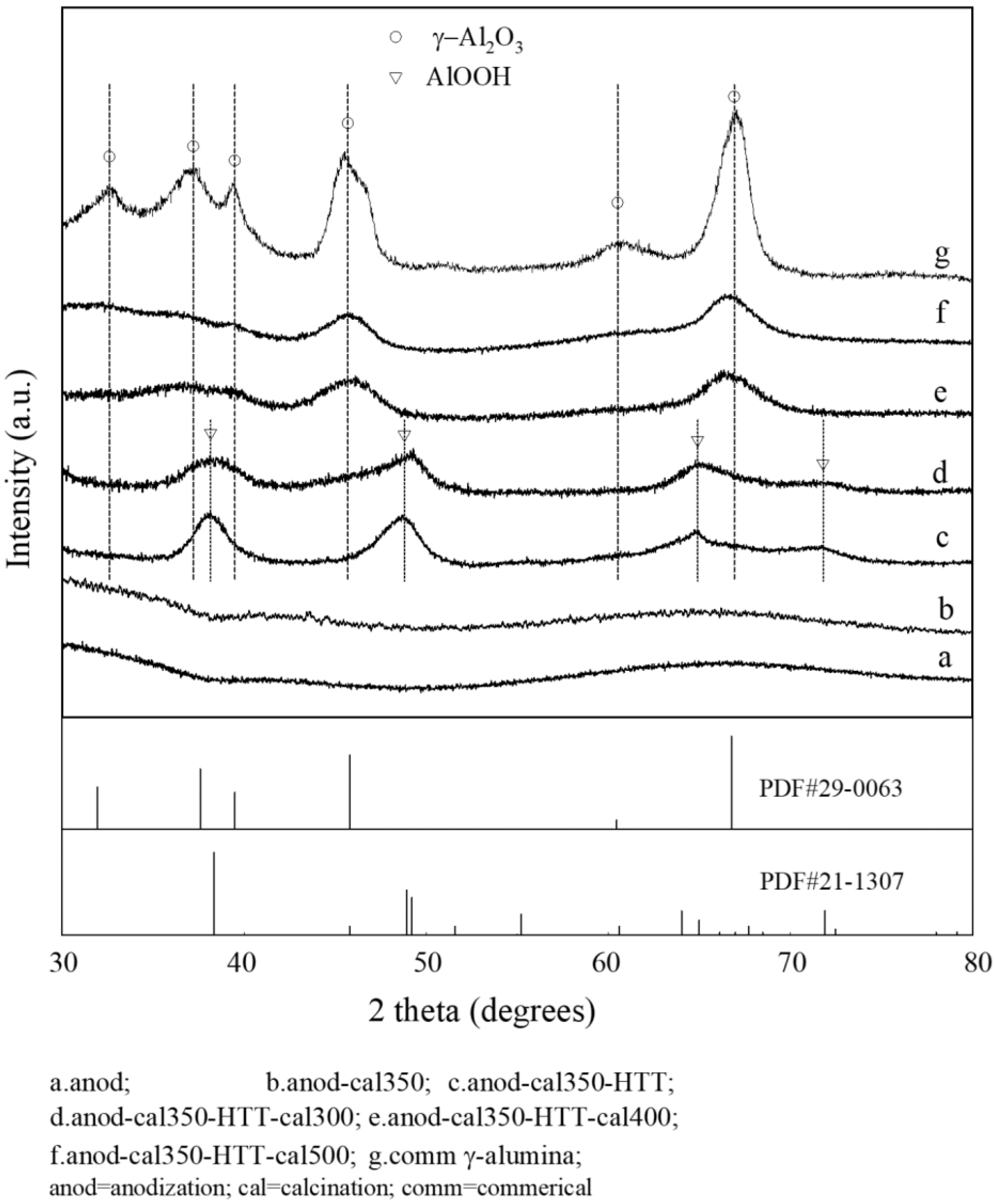
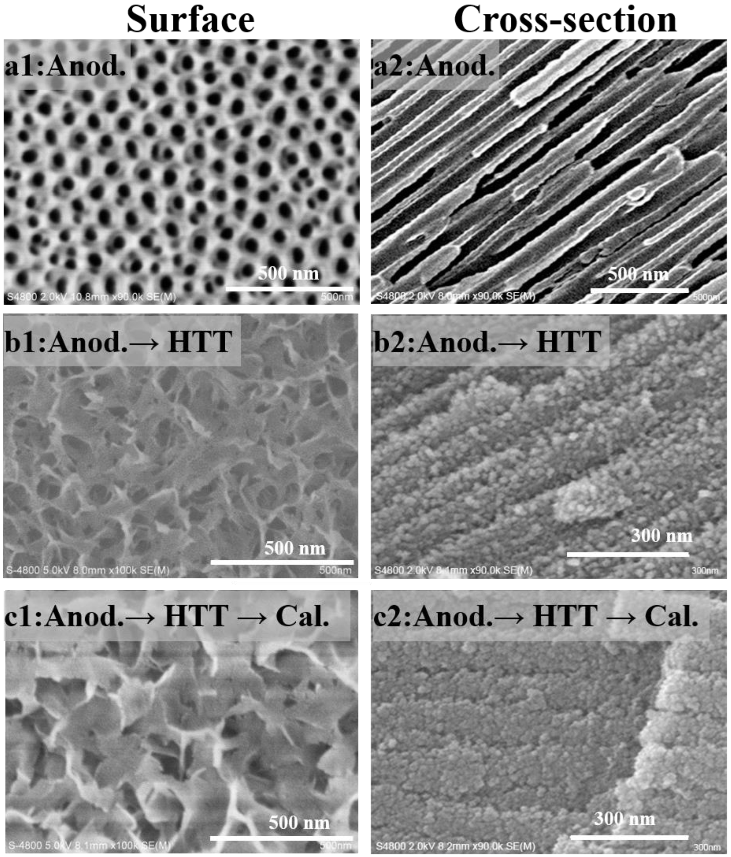
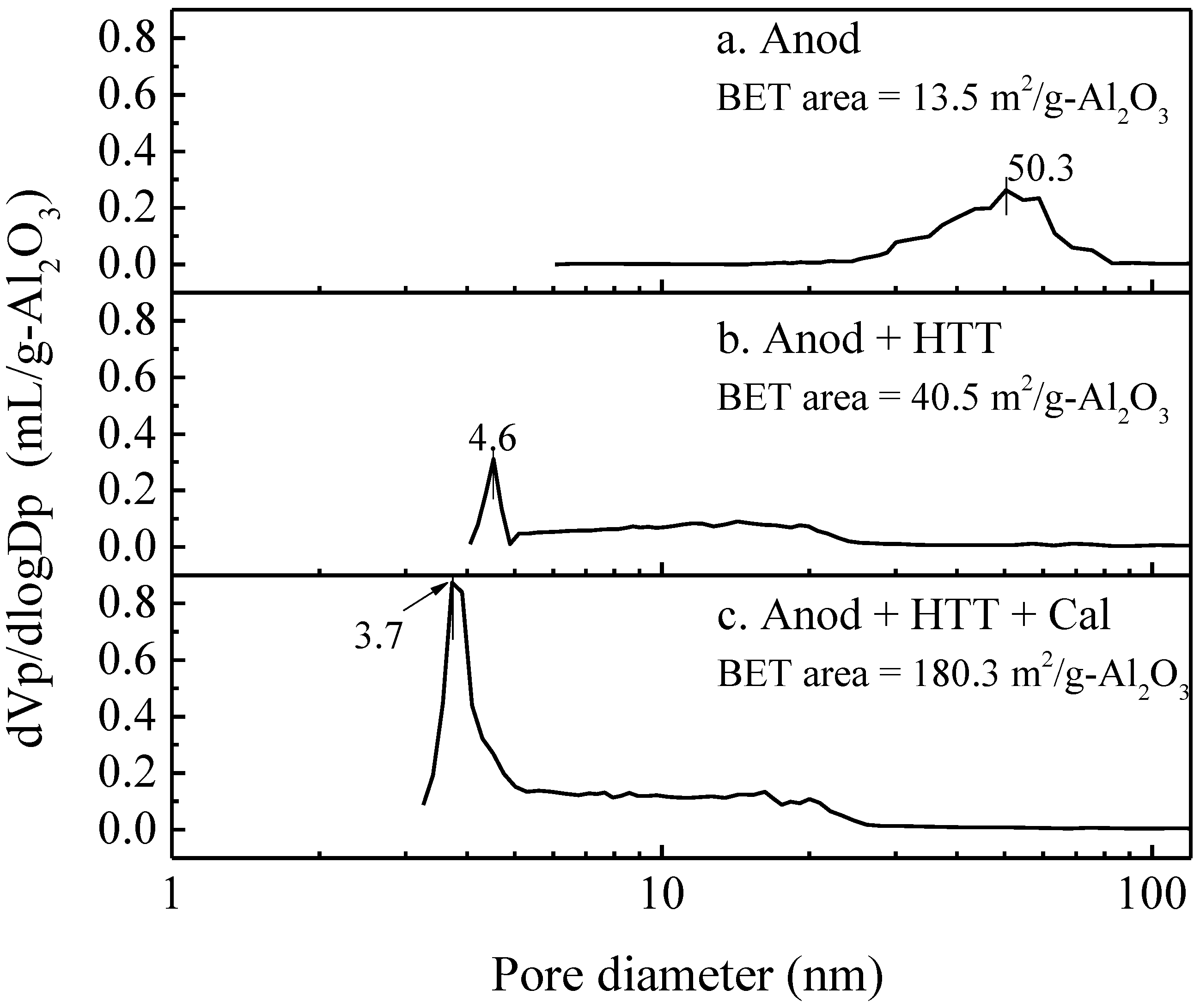
Hydrothermal treatment and subsequent high-temperature calcination can transform amorphous skeletal alumina in the conventional PAA layer into r-alumina, and significantly increase its specific surface area, without destroying the macroscopically integrated structure and microscopically ordered pore structure of the PAA material.
(2)
The ΔT-gas (temperature difference between the channel wall and the center of the gas phase) of the thin-walled catalyst is only 30% of that of the particulate catalyst, indicating the potential advantages of the CPR reactor in terms of heat transfer and energy savings.
(3)
Insufficient transverse mass transfer and backmixing are two major factors affecting reformer performance, especially when the L/D (or L/W) is small and the channel height is large.
(4)
For tube-type channels, an L/D of 10~35 and a diameter of 5~20 mm are favorable choices. Moreover, for box-type type channels, the L/W and the height should be set to 2~4 and 2~5 mm, respectively.
(5)
For box-type channels, the number of gas inlet ports has a significant effect on the reformer’s performance. The distribution state provided by two inlet ports is close to the ideal distribution state.
(6)
The box-type channel has the potential for reactor downsizing, but it is not as good as the tube-type channel in terms of gas distribution homogeneity and ease of manufacturing.

Author Contributions

Methodology, C.G. and X.Z.; software, S.D. and Y.L.; validation, J.H.; formal analysis, J.H.; investigation, L.D.; writing—original draft preparation, S.D.; writing—review and editing, S.D.; supervision, S.J. and Y.G. All authors have read and agreed to the published version of the manuscript.

Funding

The authors thank the National Natural Science Foundation of China (22108116) and Natural Science Foundation of Jiangsu Province (BK20200688) for the funding received.

Data Availability Statement

Data sharing is not applicable to this article as no new data were created or analyzed in this study.

Acknowledgments

The authors thank the National Natural Science Foundation of China (22108116) and Natural Science Foundation of Jiangsu Province (BK20200688) for the funding received. We thank Wei Zhao (Hangzhou Kaiming Catalyst Co., Ltd.) for the literature review updating and the final proofreading during the process of revising manuscript.

Conflicts of Interest

The authors declare no conflict of interest.

Nomenclature

Cpheat capacity at constant pressure [J/(kg K)]
Ddiameter of reformer tube [mm]
Deffeffective diffusion coefficient [m2/s]
Drgas diffusion coefficient [m2/s]
Ekctivation energy [kJ/mol]
F/wspace velocity [mL/(g-cat h)]
F0Fourier number [-]
Hchannel height [m]
kjArrhenius kinetic parameter of reaction j [mol bar-2/(kg-cat s)]
Kjadsorption constant of species component j [bar2]
Lchannel length [m]
MWmolecular weight of species [kg/mol]
ppressure [Pa]
Qheat source [W/m3]
Rgas constant [J/(mol K)]
Rireaction rate [kg/(m3-cat s)]
ReReynolds number [-]
S/Csteam to carbon ratio [-]
Ttemperature [°C]
Wchannel width [cm]
W1reaction rate [mol/(kg-cat s)]
W2reaction rate [mol/(kg-cat s)]
Rradius [m]
uvelocity [m/s]
ttime [s]
λthermal conductivity [W/(m K)]
kthermal conductivity [W/(m K)]
ρdensity [kg/m3]
ωmass fraction [-]
μviscosity [kg/(m s)]
Subscript and superscript
1Done-dimensional
2Dtwo-dimensional
3Dthree-dimensional
AlOOHboehmite
CPRcatalytic plate reactor
HTThydrothermal treatment
PAAporous anodic alumina
PDEpartial differential equations
WGSwater–gas shift reaction
SRMsteam reforming of methane
catcatalyst
icomponent of the reactants
jreformer layers (j = 1, catalyst layer; j = 2, gas phase layer)

Appendix A

Heat capacity: C p i ( T ) = a + b T + c T 2 .
Thermal conductivity: λ m i x ( T ) = i = 1 5 y i λ i ( T T 0 i ) 0.75 .
Diffusion coefficient: D r i ( T ) = D r 0 × ( T T 0 ) 1.75 .
Dri is calculated for a binary mixture of i-th component species of H2O.
Diffusion in the catalyst layer: D e f f , i = ε τ [ ( 97 R p T M i ) 1 + 1 D r , i ] 1 .

References

  1. Yong, Z.; Shirong, H.; Xiaohui, J.; Yuntao, Y.; Mu, X.; Xi, Y. Characteristics of proton exchange membrane fuel cell considering “dot matrix” gas distribution zones and waveform staggered flow field with cooling channels. Energy Convers. Manag. 2022, 267, 115881–115902. [Google Scholar] [CrossRef]
  2. Wang, Z.X.; Mao, J.K.; He, Z.Z.; Liang, F.L. Fuzzy control based on iQPSO in proton-exchange membrane fuel-cell temperature system. J. Energy Eng. 2020, 146, 04020044–04020057. [Google Scholar] [CrossRef]
  3. Zhao, J.J.; Li, S.; Tu, Z.K. Development of practical empirically and statistically-based equations for predicting the temperature characteristics of PEMFC applied in the CCHP system. Int. J. Hydrogen Energy 2023, 158, 17285–17295. [Google Scholar] [CrossRef]
  4. Jannelli, E.; Minutillo, M.; Perna, A. Analyzing microcogeneration systems based on LT-PEMFC and HT-PEMFC by energy balances. Appl. Energy 2013, 108, 82–91. [Google Scholar] [CrossRef]
  5. Zhao, Y.M.; Xue, H.Q.; Jiang, L.Y.; Jin, X.; Fu, H.H.; Xie, X.F. Proposal and assessment of a solid oxide fuel cell cogeneration system in order to produce high-temperature steam aiming at industrial applications. Appl. Therm. Eng. 2023, 221, 119882–119895. [Google Scholar] [CrossRef]
  6. De Falco, M.; Santoro, G.; Capocelli, M.; Caputo, G.; Giaconia, A. Hydrogen production by solar steam methane reforming with molten salts as energy carriers: Experimental and modelling analysis. Int. J. Hydrogen Energy 2021, 46, 10682–10696. [Google Scholar] [CrossRef]
  7. Wang, Z.X.; Mao, J.K.; Xu, L.G.; Yang, M.L.; Cheng, M.; Chen, Z.Y.; Liang, F.L. Thermodynamic evaluation of a 5 kW kerosene-fueled PEMFC-based cogeneration system: Component-level and system-level analysis. Energy. Convers. Manag. 2023, 277, 116600–116615. [Google Scholar] [CrossRef]
  8. Fazil, Q.; Mohammad, Y.; Mohd, K.; Hussameldin, I.; Bernard, E.; Hesam, K.; Mohammed, M.R.; Ashok, K.N.; Shreeshivadasan, C. A state-of-the-art review on the latest trends in hydrogen production, storage, and transportation techniques. Fuel 2023, 340, 127574–127591. [Google Scholar]
  9. Qureshi, F.; Yusuf, M.; Pasha, A.A.; Khan, H.W.; Imteyaz, B.; Irshad, K. Sustainable and energy efficient hydrogen production via glycerol reforming techniques: A review. Int. J. Hydrogen Energy 2022, 47, 41397–41420. [Google Scholar] [CrossRef]
  10. Rahimipetroudi, I.; Shin, J.S.; Rashid, K.; Yang, J.B.; Dong, S.K. Development and CFD analysis for determining the optimal operating conditions of 250 kg/day hydrogen generation for an on-site hydrogen refueling station (HRS) using steam methane reforming. Int. J. Hydrogen Energy 2021, 46, 35057–35076. [Google Scholar] [CrossRef]
  11. Cherif, A.; Lee, J.S.; Nebbali, R.; Lee, C.J. Novel design and multi-objective optimization of autothermal steam methane reformer to enhance hydrogen production and thermal matching. Appl. Therm. Eng. 2022, 217, 119140–119154. [Google Scholar] [CrossRef]
  12. Qureshi, F.; Yusuf, M.; Kamyab, H.; Vo, D.V.N.; Chelliapan, S.; Joo, S.-W.; Vasseghian, Y. Latest eco-friendly avenues on hydrogen production towards a circular bioeconomy: Currents challenges, innovative insights, and future perspectives. Renew. Sust. Energy Rev. 2022, 168, 112916–112931. [Google Scholar] [CrossRef]
  13. Upadhyay, M.; Lee, H.; Kim, A.; Lee, S.H.; Lim, H. CFD simulation of methane steam reforming in a membrane reactor: Performance characteristics over range of operating window. Int. J. Hydrogen Energy 2021, 40, 30402–30411. [Google Scholar] [CrossRef]
  14. Ngo, S.I.; Lim, Y.; Kim, W.; Seo, D.J.; Yoon, W.L. Computational fluid dynamics and experimental validation of a compact steam methane reformer for hydrogen production from natural gas. Appl. Energy 2019, 236, 340–353. [Google Scholar] [CrossRef]
  15. Katebah, M.; Abousrafa, A.; Linke, P. Hydrogen production using piston reactor technology: Process design and integration for CO2 emission reduction. Energy 2022, 259, 124999–125014. [Google Scholar] [CrossRef]
  16. Yusuf, M.; Farooqi, A.S.; Ying, Y.X.; Keong, L.K.; Alam, M.A.; Hellgardt, K. Syngas production employing nickel on alumina-magnesia supported catalyst via dry methane reforming. Materialwiss. Werkstofftech. 2021, 52, 1090–1100. [Google Scholar] [CrossRef]
  17. Wang, J.Y.; Yang, J.; Sunden, B.; Wang, Q.W. Hydraulic and heat transfer characteristics in structured packed beds with methane steam reforming reaction for energy storage. Int. Commun. Heat Mass Transf. 2021, 121, 105109–105122. [Google Scholar] [CrossRef]
  18. Ding, H.R.; Tong, S.R.; Qi, Z.F.; Liu, F.; Sun, S.E.; Han, L. Syngas production from chemical-looping steam methane reforming: The effect of channel geometry on BaCoO3/CeO2 monolithic oxygen carriers. Energy 2022, 185, 126000–126009. [Google Scholar] [CrossRef]
  19. Oh, Y.S.; Nam, J.H. A numerical study on the active reaction thickness of nickel catalyst layers used in a low-pressure steam methane reforming process. Int. J. Hydrogen Energy 2021, 46, 7712–7721. [Google Scholar] [CrossRef]
  20. Kevin, M.; Van, G.; Vladimir, V. Making chemicals with electricity. Science 2019, 364, 734–735. [Google Scholar]
  21. Zhang, C.Q.; Pu, Y.J.; Wang, F. Hydrothermal treatment of metallic-monolith catalyst support with self-growing porous anodic-alumina film. Chin. J. Chem. Energy 2020, 28, 1311–1319. [Google Scholar] [CrossRef]
  22. Stefanidis, G.D.; Vlachos, D.G. Methane steam reforming at microcales: Operation strategies for variable power output at millisecond contact times. AIChE J. 2009, 51, 180–191. [Google Scholar] [CrossRef]
  23. Farsi, A.; Shadravan, V.; Mansouri, S.S.; Zahedi, G.; Manan, Z.A. A new reactor concept for combining oxidative coupling and steam re-forming of methane: Modeling and analysis. Int. J. Hydrogen Energy 2013, 37, 129–152. [Google Scholar] [CrossRef]
  24. Fukuda, T.; Harada, M.R.; Ookawara, S. Double-layered catalytic wall-plate microreactor for process intensification of dry reforming of methane: Reaction activity improvement and coking suppression. Chem. Eng. Process 2021, 164, 108406–108414. [Google Scholar] [CrossRef]
  25. Hamzah, A.B.; Fukuda, T.; Ookawara, S. Process intensification of dry reforming of methane by structured catalytic wall-plate microreactor. Chem. Eng. J. 2021, 412, 128636–128646. [Google Scholar] [CrossRef]
  26. Pashchenko, D.; Eremin, A. Heat flow inside a catalyst particle for steam methane reforming: CFD-modeling and analytical solution. Int. J. Heat Mass Transf. 2021, 165, 120617–120624. [Google Scholar] [CrossRef]
  27. Wang, Z.X.; Mao, J.K.; He, Z.Z.; Liang, F.L. Energy-exergy analysis of an integrated small-scale LT-PEMFC based on steam methane reforming process. Energy. Convers. Manag. 2021, 246, 114685–114699. [Google Scholar] [CrossRef]
  28. Oliveira, E.; Grandem, C.A.; Rodriguesm, A.E. Steam methane reforming in a Ni/Al2O3 catalyst: Kinetics and diffusional limitations in extrudates. Can. J. Chem. Eng. 2009, 87, 945–956. [Google Scholar] [CrossRef]
  29. Xu, J.G.; Froment, G. Methane steam reforming, methanation and water-gas shift: I. Intrinsic kinetics. AIChE J. 1989, 35, 88–96. [Google Scholar] [CrossRef]
  30. Sprung, C.; Arstad, B.; Olsbye, U. Methane steam reforming over a Ni/NiAl2O4 model catalyst-kinetics. Chemcatchem 2014, 6, 1969–1982. [Google Scholar] [CrossRef]
  31. Numaguchi, T.; Kikuchi, K. Intrinsic kinetics and design simulation in a complex reaction network: Steam-methane reforming. Chem. Eng. Sci. 1988, 43, 2295–2301. [Google Scholar] [CrossRef]
  32. Liu, M.H.; Shi, Y.X.; Cai, N.S. Modeling of packed bed methanol steam reformer integrated with tubular high temperature proton exchange membrane fuel cell. J. Therm. Sci. 2023, 32, 81–92. [Google Scholar] [CrossRef]
  33. Seiiedhoseiny, M.; Ghasemzadeh, K.; Jalilnejad, E.; Iulianelli, A. Computational fluid dynamics study on concentration polarization phenomena in silica membrane reactor during methanol steam reforming. Chem. Eng. Process.-Process Intensif. 2023, 183, 109249–109262. [Google Scholar] [CrossRef]
  34. Chen, W.H.; Lu, C.Y.; Tran, K.; Lin, Y.L.; Naqvi, S.R. A new design of catalytic tube reactor for hydrogen production from ethanol steam reforming. Fuel 2020, 281, 118746–118760. [Google Scholar] [CrossRef]
  35. Hania, G.; Muhammad, Y.A.; Muhammad, W.T. Production of H2 via sorption enhanced auto-thermal reforming for small scale Applications-A process modeling and machine learning study. Int. J. Hydrogen Energy 2023, 2023 6, 12622–12635. [Google Scholar]
  36. Ma, J.; Jiang, B.; Tang, D.W. Deciphering high-efficiency solar-thermochemical energy conversion process of heat pipe reactor for steam methane reforming. Fuel 2022, 326, 124972–124981. [Google Scholar] [CrossRef]
  37. Guo, Y.; Zhou, L.; Kameyama, H. Thermal and hydrothermal stability of a metal monolithic anodic alumina support for steam reforming of methane. Chem. Eng. J. 2011, 168, 341–350. [Google Scholar] [CrossRef]
  38. Hong, R.R.; Feng, J.T.; He, Y.F.; Li, D.Q. Controllable preparation and catalytic performance of Pd/anodic alumina oxide@Al catalyst for hydrogenation of ethylanthraquinone. Chem. Eng. Sci. 2015, 135, 274–284. [Google Scholar] [CrossRef]
  39. Cussler, E.L. Diffusion: Mass Transfer in Fluid Systems, 2nd ed.; Cambridge University Press: Cambridge, UK, 1997; pp. 100–102. [Google Scholar]
Figure 1. Schemas of box-type (a) and tube-type (c) reformer cells (the reformer cells can be scaled up as (b) and (d)), (Symbols description: D = diameter, H = height, W = width, L = length, X = X-axis, Y = Y-axis, Z = Z-axis.
Energies 16 03426 g001
Figure 2. Pre-defined temperature distribution along the combustion catalyst surface of the reformer channel.
Energies 16 03426 g002
Figure 3. Schematic diagram of the preparation process of anodic alumina support.
Energies 16 03426 g003
Figure 4. XRD patterns of the PAA materials with different post-treatments.
Energies 16 03426 g004
Figure 5. SEM images of the PAA materials with different post-treatments.
Energies 16 03426 g005
Figure 6. Pore-size distribution of PAA materials with different post-treatments.
Energies 16 03426 g006
Figure 7. (a) SRM activity obtained on anodic alumina catalysts (dashed lines are thermodynamic equilibrium data, F/w = 150,000 mL/g-cat/h); (b) catalyst stability at different space velocities.
Energies 16 03426 g007
Figure 8. Figure 8. Comparison of the experimental reaction rates and calculated reaction rates.
Energies 16 03426 g008
Figure 9. Velocity distribution in gas phase (a): box-type; (b): tube-type).
Energies 16 03426 g009
Figure 10. Transverse temperature differences along the length of the reforming channel between the combustion catalyst and the reforming catalyst (ΔT-cat.) and that between the reforming catalyst and the gas phase center (ΔT-gas).
Energies 16 03426 g010
Figure 11. Methane conversion of different types of reformer channels with a different L/D (for tube-type) or L/W (for box-type) under different conditions (a): tube-type, D = 6 mm; (b): tube-type, F/w = 100,000 mL/g-cat/h; (c): box-type, H = 3 mm and W = 2 cm; (d): box-type, F/w = 100,000 mL/g-cat/h and W = 2 cm).
Energies 16 03426 g011aEnergies 16 03426 g011b
Figure 12. Methane conversion and invalid methane molecule ratio η at different L/D (tube-type, D = 6 mm, 100,000 mL/g-cat/h).
Energies 16 03426 g012
Figure 13. Hydrogen streamline (red lines and red arrows) and velocity field (sectors) in a tube-type channel. (L/D = 5, D = 6 mm, 100,000 mL/g-cat/h).
Energies 16 03426 g013
Figure 14. Molar fraction of hydrogen along the central axis of the tube-type channel (100,000 mL/g-cat/h).
Energies 16 03426 g014
Figure 15. Relationship between the number of inlet ports and the performance of the box-type channel at different L/W (a) and channel height (b) (F/w = 100,000 mL/g-cat/h, W = 2 cm).
Energies 16 03426 g015aEnergies 16 03426 g015b
Figure 16. Velocity distribution (a), streamline of gas (b) and concentration of methane (c) of a box-type channel with a single inlet (F/w = 100,000 mL/g-cat/h, W = 2 cm).
Energies 16 03426 g016
Figure 17. Sample of tube-type Al/Fe–Cr alloy/Al-clad substrate with a diameter of 20 mm.
Energies 16 03426 g017
Table 1. Reaction conditions and catalyst parameters.
Gas PhaseS/C3
Pressure101,325 Pa
Inlet temperature723 K
CatalystCatalyst18 wt.% Ni/γ-Al2O3/alloy
DensityAlumina layer1900 kg/m3
Alloy layer3900 kg/m3
ThicknessAlumina layer40 um
Alloy layer50 um
Thermal-conductivityAlumina layer1.039 W/m/K
Alloy layer11.3 W/m/K
Table 2. Arrhenius parameter values for reforming and water–gas shift reactions.
ConstantAE (kJ/mol)
k1 (mol bar−2/(kg-cat s))1.54 × 1014191
k2 (mol bar−4/(kg-cat s))3.97 × 10859.8
K1 (bar2)exp (−26,830/T + 30.114)
K2 (−)exp (4400/T − 4.036)
Table 3. Comparison of the box-type reforming channel and the tube-type (methane conversion 0.9).
Tube-Type Reformer ChannelBox-Type Reformer Channel
Flow rate2.4 L/min
Cat. Size77.7~111.6 cm254.4~84 cm2
Height (D, H)5~15 mm2~5 mm
Width4 cm
volume9.71~41.8 cm36.4~21 cm3
Disclaimer/Publisher’s Note: The statements, opinions and data contained in all publications are solely those of the individual author(s) and contributor(s) and not of MDPI and/or the editor(s). MDPI and/or the editor(s) disclaim responsibility for any injury to people or property resulting from any ideas, methods, instructions or products referred to in the content.

