Article

Improving the Efficiency of Organic Solar Cells via the Molecular Engineering of Simple Fused Non-Fullerene Acceptors

1
Enikolopov Institute of Synthetic Polymeric Materials of the Russian Academy of Sciences, Profsoyuznaya St. 70, Moscow 117393, Russia
2
The Institute for Advanced Studies, Wuhan University, Wuhan 430072, China
3
Scientific and Research Centre Kurchatov Institute, 1 Kurchatov Square, Moscow 123182, Russia
*
Authors to whom correspondence should be addressed.
Energies 2023, 16(8), 3443; https://doi.org/10.3390/en16083443
Submission received: 14 December 2022 / Revised: 3 March 2023 / Accepted: 11 April 2023 / Published: 14 April 2023

Abstract

:
The development of novel non-fullerene small-molecule acceptors (NFAs) with a simple chemical structure for high-performance organic solar cells (OSCs) remains an urgent research challenge to enable their upscaling and commercialization. In this work, we report on the synthesis and comprehensive investigation of two new acceptor molecules (BTPT-OD and BTPT-4F-OD), which have one of the simplest fused structures among the Y series of NFAs, along with the medium energy bandgap (1.85 eV–1.94 eV) and strong absorption in the visible and near-IR spectral range (700–950 nm). The novel NFAs have high thermal stability, good solubility combined with a high degree of crystallinity, and deep-lying levels of the lowest unoccupied molecular orbital (up to −3.94 eV). The BTPT-OD with indan-1-one-3-dicyanvinyl terminal acceptor group is superior to its counterpart BTPT-4F-OD with 5,6-difluorindan-1-one-3-dicyanvinyl group both in the number of synthetic steps and in the photovoltaic performance in OSCs. PM6:BTPT-OD systems exhibit superior photovoltaic performance due to the higher charge mobility and degree of photoresponsiveness, faster carrier extraction, and longer carrier lifetime. As a result, BTPT-OD has almost two times higher photovoltaic performance with PM6 as a donor material due to the higher JSC and FF than BTPT-4F-OD systems. The results obtained indicate that further development of OSCs can be well achieved through a rational molecular design.

1. Introduction

In the past few years, organic solar cells (OSСs) have rapidly achieved a high power conversion efficiency (PCE) of over 19%, mostly due to significant advances in the development of non-fullerene acceptors (NFAs) for the photoactive layer of OSСs and the optimization of bulk heterojunction (BHJ) photovoltaic devices [1,2,3,4,5,6,7,8,9]. A distinctive feature of OSCs compared to other types of photovoltaic cells such as quantum dot-sensitized solar cells (QDSCs) and perovskite solar cells (PSCs) is the possibility of obtaining flexible, lightweight, semitransparent devices, which allows them to be integrated into buildings, vehicles, textiles, or wearable electronics [10,11,12,13,14,15,16,17]. Additionally, the possibility of manufacturing through modern low-cost and fast printing technologies as well as the expected lifetime of more than 10 years [18,19,20] make OSCs particularly attractive from an economic point of view [21,22,23].
The development of electron donor and electron acceptor materials plays a key role in the efficient functioning of organic photovoltaic devices. Compared to fullerene-based acceptor materials, NFAs offer significant advantages. Due to the possibility of a wide variation of structural units in NFA molecules, the properties of such compounds (absorption spectrum, thermal, structural and charge-transporting properties, morphology, etc.) can be finely tuned for a certain donor material. The discovery of Y-like structures (Y6 and its derivatives) has led to great interest among researchers. Y6-based OSCs exhibited the expanded absorption of light (up to 950 nm) and sufficient drive force to produce a large JSC over 25 mA/cm2 and characterized by a low energy loss, resulting in an impressive PCE of 15.7% [24,25,26]. Tens of different Y-like NFAs have been reported [21,27]. This class of NFAs is among the most promising, and a PCE of over 19% has been achieved using them in single-junction OSCs [7,9,25,28]. However, there are still unresolved essential issues, primarily related to the complexity of the synthesis of Y-like NFAs, which hinder their commercialization. Moreover, the structure–property–device performance correlations are not completely understood. Therefore, the search for novel efficient Y-like NFAs with a simple chemical structure and the investigation of their properties are urgent issues.
Earlier attempts have been made to simplify the structures of the Y-series molecules [24,29,30,31,32]. The BTPT-4F being one of the simplest Y-like molecules demonstrated a PCE of 1.09% in single-junction OSCs [24]. The authors explained the low PCE mainly by the limited solubility of BTPT-4F and strong aggregation in the photoactive layer. However, it is still confusing how the individual change in the fused-ring skeleton length or side alkyl chains affects the photovoltaic properties of the molecule, especially film morphology and electron mobility.
In this work, we synthesized two novel NFAs with one of the simplest Y-series structures, containing a central fragment based on benzo[c][1,2,5]thiadiazole, thieno [2′,3′:4,5]pyrrol, solubilizing 2-octyldodecyl chains and either indan-1-one-3-dicyanvinyl (BTPT-OD) or 5,6-difluoro-indan-1-one-3-dicyanvinyl (BTPT-4F-OD) terminal acceptor units (Figure 1). Generally, introducing additional non-covalent interactions such as F···H and F···π interactions diversifies packing patterns. Fluorine-free NFAs show face-to-face and compact packing, while fluorinated NFAs show more complex and compact 3D stacking [33]. One would expect that the molecular packing of fluorinated compounds should be more compact and, therefore, the devices based on them should exhibit high charge mobility and PCE. However, in this work, we observed that the simpler and fluorine-free BTPT-OD has higher values of charge mobility and PCE with PM6 as a donor material as compared to its more complicated analog—BTPT-4F-OD with the terminal fluorine-containing acceptor groups.

2. Materials and Methods

2.1. Materials

Thiophene, triphenylphosphine, tetrakis(triphenylphosphine) palladium (0), tributyltin chloride, 2,1,3-benzothiadiazole, 1,1-dicyanomethylene-3-indanone and n-butyllithium (n-BuLi) (2.5 M concentration solution in hexane) were acquired from Sigma-Aldrich Co. and used without further purification. According to the known methods, o-dichlorobenzene (o-DCB), toluene, dimethylformamide (DMF), dimethyl sulfoxide (DMSO), ethylene dichloride (EDC), and pyridine were purified and dried, and then used as solvents. All reactions, unless stated otherwise, were performed in an inert argon atmosphere using anhydrous solvents. In the case of column chromatography, silica gel 60 (Merck, Darmstadt, Germany) R was taken. PM6 and were purchased from Solarmer Materials Inc., Beijing., China.
4,7-Dibromo-5,6-dinitrobenzo[c][1,2,5]thiadiazole (1) [34], 2-(tributylstannyl) thiophene [35], 1-bromo-2-octyldodecane [36], 2-(5,6-difluoro-3-oxo-2,3-dihydro-1H-inden-1-ylidene)malononitrile [37] were obtained as reported elsewhere.

2.2. General Methods

“Bruker WP-250 SY” spectrometer was used for the registering of 1H NMR spectra with operation at 250.13 MHz and using the signal of CDCl3 (7.25 ppm) as a reference standard. Solutions of the analyzed molecules (1%) in CDCl3 were used in the case of 1H NMR spectroscopy. 13C NMR spectra were recorded using a “Bruker Avance II 300” spectrometer at 75 MHz. The analyzed molecules were taken in the form of 5% solutions in CDCl3 for 13C NMR spectroscopy. ACD Labs software was used for the subsequent interpretation of the spectra.
Using the Autoflex II Bruker (resolution FWHM 18,000), equipped with a nitrogen laser (work wavelength 337 nm) and time-of-flight mass-detector working in reflections mode Mass-spectra (MALDI-TOF) were recorded (the accelerating voltage was 20 kV). The samples were deposited on a polished stainless-steel substrate. The spectrum was registered in the positive ion mode. The registration of the sample took place at different points, and as a consequence, the resulting spectrum was the sum of 300 spectra. The matrices were 2,5-dihydroxybenzoic acid (DHB) (Acros, 99%) and α-cyano-4-hydroxycinnamic acid (HCCA) (Acros, 99%).
UV–Vis absorption spectra were recorded on a Shimadzu UV-2501PC (Kyoto, Japan) spectrophotometer in the standard 10 mm photometric quartz cuvette using CHCl3 solutions with the concentrations of 10−5 M. Thin films subject to UV−vis-NIR absorption measurement were spin-casted from chloroform solutions with concentration 10 g/L on optically transparent glass. Analysis of light intensity dependent. All measurements were carried out at room temperature.
Cyclic voltammetry measurements were measured using IPC-Pro M potentiostat. Solid compact layers of the samples obtained by electrostatically rubbing the materials onto a glass-carbon electrode were used. Acetonitrile solution using 0.1 M Bu4NPF6 as a supporting electrolyte was used for the experiment. The scan rate was 200 mV s−1. Potentials were quantified in relation to the saturated calomel electrode (SCE). Measurements of film CV were performed in a standard three-electrode cell equipped with the working glass-carbon electrode (s = 2 mm2), the platinum plate as the counter electrode, and the SCE as the reference electrode. The energies of the highest occupied molecular orbital (HOMO) and the lowest unoccupied molecular orbital (LUMO) were estimated using the first standard oxidation (φox) and reduction (φred) potentials derived from CV experiments as E(HOMO) = −e(φox + 4.40) (eV) and E(LUMO) = −e(φred + 4.40) (eV), where e is the elementary charge [38,39].
Thermogravimetric analysis (TGA) was measured in a dynamic mode in the temperature range of 30–700 °C using an “STA JUPITER 443 F3 NETZSCH” system (Germany). The heating/cooling rate was 10 °C/min. Molecules were investigated in air and argon flow of 200 mL/min.
“Mettler Toledo DSC30” system was used for Differential scanning calorimetry (DSC) scans using a heating/cooling rate of 20 °C/min in the temperature range of +20–250 °C and N2 flow of 50 mL/min for the samples.
The 2D wide-angle (WAXS) analysis of the samples was carried out at the Kurchatov synchrotron (National Research Center Kurchatov Institute) using the BioMUR station. A 1.7 T bending magnet operating at 8 keV (1.445 A) energy, dE/E of 10–3 resolution, and 109 photon flux was applied as a source of radiation. Dectris Pilatus 1 M detector was used for the registration of diffraction patterns. The beam size at a sample was 0.3 × 0.2 mm2 with the distance from the sample to the detector was approximately 150 mm. Silver behenate and NaC(Na2Ca3Al2F14) were taken as calibration standards and the exposure time was 5 min. Fit2D V18.002 Andy Hammersly/ESRF software was used to integrate and process data.
For performance measurements, the control solar cell devices were manufactured using a regular structure of glass/ITO/PEDOT:PSS (40 nm)/Active layer (donor: acceptor (D:A = 1:1.2) for bulk heterojunction (BHJ) blend)/PNDIT-F3N(5 nm)/Ag. The ITO glass has a resistance of around 10 ohms and is cleaned by ultrasonication with deionized water, acetone, and isopropyl alcohol for 15 min each in turn. ITO substrates were cleaned in a UV-ozone purification system for 15 min, after drying by blowing with dry nitrogen. Then, the spin-coating method was used to apply a thin layer of PEDOT:PSS (Xi’an Polymer Light Technology Corp 4083) to the pre-cleaned ITO-coated glass at 4500 rpm for 20 s and then dried at 150 °C for 15 min in an air atmosphere. Solutions of PM6:BTPT-4F-OD or PM6:BTPT-OD with a total concentration of 16 mg mL−1 in chloroform were used to prepare the photovoltaic layers due to spin-coating method (3500 rpm for 30 s) in a glovebox followed by thermal annealing at 100 °C for 10 min. A PNDIT-F3N layer with a solution concentration of 1 mg/mL was precipitated on top of the active layer at a rate of 4000 rpm for 30 s. Finally, the top silver electrode (100 nm thickness) was thermally evaporated through a mask onto the cathodic buffer layer under a vacuum of ~5×10⁻⁶ mbar.
The current-voltage characteristics of the solar cells were determined with a Keithley 2400 source meter unit under AM1.5G (100 mW cm−2) irradiation from a solar simulator (Enlitech model SS-F5-3A). Solar simulator illumination intensity was defined at 100 mW cm−2 using a monocrystalline silicon reference cell with a KG5 filter. Short-circuit currents under AM1.5G (100 mW cm−2) conditions were evaluated by the spectral response and convolution with the solar spectrum. Part measuring conditions: scanning voltage from 0.0 V to 1.2 V; the step is 0.02 V; the delay time is 1 ms and the scan mode is sweep.
The external quantum efficiency was measured by a Solar Cell Spectral Response Measurement System QE-R3011(Enli Technology Co., Ltd., Kaohsiung, Taiwan).
Atomic force microscopy (AFM) measurements were measured using a Nano Wizard 4 atomic force microscopy (JPK Inc., Berlin, Germany) in Qi mode to investigate the film’s surface morphologies.
Transient photocurrent (TPC) measurements: the corresponding solar cells were excited by a laser diode with a wavelength of 405 nm. The transient photocurrent of the short-circuit devices responded to a 200 μs square pulse from the LED without background illumination. The current traces were measured on a Tektronix DPO3034 digital oscilloscope by recording the voltage drop across a 5-ohm sensor resistor in series with the solar cell. The DC voltage was supplied to the solar cell with an MRF544 bipolar junction transistor in a common collector amplifier configuration.
Transient photovoltage (TPV) measurements were made under open-circuit conditions (1 MΩ), when the devices were directly plugged into an oscilloscope. Then white light LED with various light intensities was used for the illumination of the device. A small optical perturbation was applied with a 405 nm laser diode whose light intensity was controlled to create a voltage perturbation of ∆VO < 10 mV << VOC. The number of charges generated by the pulse was derived by integrating a photocurrent measurement (50 Ω) without bias light.
J-V characteristics: the variation of JSC as a function of light intensity (decrement of change is set (from 100 to 10 through 10, and 8, 5) calibrated with standard silicon) was investigated.
Space-charge-limited-current (SCLC) measurements were performed using single-carrier designed devices. The dark current-voltage characteristics in the space charge limited (SCL) mode were quantified and analyzed according to the reference. The structure of Glass/ITO/ZnO/Active layer/PNDIT-F3N/Ag (100 nm) was used for the electron-only devices and Glass/ITO/PEDOT:PSS/Active layer/MoO3/Ag (100 nm) structure was used for the hole only devices, where the Ag was vaporized.

2.3. Synthetic Procedures

5,6-dinitro-4,7-di(2-thienyl)-2,1,3-benzothiadiazole (2). Under an inert atmosphere 2-(tributylstannyl)thiophene (7.8 g, 20.9 mmol), 4,7-dibromo-5,6-dinitrobenzo[c] [1,2,5]thiadiazole (3.7 g, 9.6 mmol) and Pd(PPh3)4 (0.45 g, 0.4 mmol) were dissolved in 160 mL of dry toluene and stirred at reflux for 4 h. After completeness of the reaction, the reaction mixture was concentrated under reduced pressure. The crude product was chromatographically purified on a silica gel column eluted with toluene and then recrystallized from petroleum ether to afford a solid. The solid was filtered and dried under a vacuum to obtain compound 2 (3.4 g, yield: 90%) as an orange solid. 1H NMR (250 MHz, CDCl3) δ (ppm) = 7.72 (dd, J1 = 5.19 Hz, J2 = 1.22 Hz, 2H), 7.50 (dd, J1 = 3.66 Hz, J2 = 1.22 Hz, 2H), 7.21 (dd, J1 = 4.89 Hz, J2 = 3.67 Hz, 2H). 13C NMR (75 MHz, CDCl3) δ (ppm) = 152.18, 141.83, 131.44, 130.96, 128.88, 128.00, 121.47. HR-MS (MALDI-TOF) m/z calcd. for (C14H6N4O4S3): 389.96. Found [MH+]: 390.87.
10,11-dihydro[1,2,5]thiadiazolo[3,4-e]thieno[3,2-b]thieno[2′,3′:4,5]pyrrolo[3,2-g]indole (3). Compound 2 (2.6 g, 6.9 mmol) and triphenylphosphine (18.6 g, 70.9 mmol) were dissolved in 30 mL of o-DCB. The reaction was stirred at 180 °C for 16 h. Then the solvent was removed under a reduced pressure to give the crude compound 5. The residue was purified by column chromatography on silica gel (2/1, toluene/ethyl acetate) to give a crude product, then, recrystallized from petroleum ether to obtain a red solid 3 (1.73 g, 78% yield). 1H NMR (250 MHz, CDCl3) δ (ppm) = 11.88 (s, 2H), 7.60 (d, J1 = 5.19 Hz, 2H), 7.41 (d, J1 = 5.19 Hz, 2H). 13C NMR (75 MHz, CDCl3) δ (ppm) = 146.94, 141.11, 129.52, 126.65, 118.95, 112.95, 106.66. HR-MS (MALDI-TOF) m/z calcd. for (C14H6N4S3): 325.98. Found: 325.94.
10,11-di(2-octyldodecyl)[1,2,5]thiadiazolo[3,4-e]thieno[3,2-b]thieno[2′,3′:4,5]pyrrolo-[3,2-g]indole (4). Compound 3 (1.20 g, 3.7 mmol), 1-bromo-2-octyldodecane (7.85 g, 21.6 mmol), potassium iodide (0.31 g, 1.8 mmol), potassium hydroxide (0.21 g, 3.7 mmol) were dissolved in DMSO (25 mL) and then the mixture was stirred at 80 °C. The completion of the reaction was monitored by TLC. The residue was extracted with ethyl acetate and H2O. The organic layers were combined and dried over Na2SO4, filtered, and purified with column chromatography on silica gel using toluene/petroleum ether (1/10, v/v) as the eluent to give yellow solid 4 (2.28 g, 70% yield). 1H NMR (400 MHz, CDCl3), δ (ppm) = 7.4 (d, J = 5.19 Hz, 2H), 7.13 (d, J = 7.19 Hz, 2H), 4.45 (d, J = 7.94 Hz, 4H), 2.05–1.91 (overlapping peaks, 2H), 1.31–1.15 (overlapping peaks, 64H), 1.07–0.71 (overlapping peaks, 12H). 13C NMR (75 MHz, CDCl3) δ (ppm) = 147.56, 145.10, 132.78, 126.41, 121.15, 112.00, 110.58, 54.30, 37.88, 31.89, 31.76, 31.35, 30.41, 29.69, 29.59, 29.53, 29.48, 29.36, 29.29, 29.12, 29.06, 25.53, 25.40, 22.68, 22.60, 14.13, 14.10. HR-MS (MALDI-TOF) m/z calcd. for (C54H86N4S3): 886.60. Found: 886.06.
10,11-bis(2-octyldodecyl)-10,11-dihydro-[1,2,5]thiadiazolo[3,4e]thieno[2′,3′:4,5]pyrrolo[3,2-g]thieno[3,2-b]indole-2,8-dicarbaldehyde (5). To a 100 mL two-necked flask, DMF (12 mL) was added and cooled to −10 °C, then phosphorus oxychloride (2.6 mL) was added dropwise. After stirring at the same temperature for 1.5 h, compound 4 (1.06 g, 1.47 mmol) in 25 mL 1,2-dichloroethane was added dropwise to the solution before being heated to room temperature and stirred overnight. The reaction mixture was allowed to cool to room temperature and the mixture was poured into water, and then extracted with dichloromethane. After the collected organic layer was washed with water and brine, the crude product was purified using silica gel using ethyl acetate/hexane (1/10, v/v) as eluent, yielding an orange solid of compound 5 (1.03 g, 90%). 1H NMR (400 MHz, CDCl3), δ (ppm) = 10.01 (s, 2H), 7.81 (s, 2H), 4.51 (d, J = 7.23 Hz, 4H), 2.04–1.93 (overlapping peaks, 2H), 1.30–1.14 (overlapping peaks, 64H), 1.08–0.78 (overlapping peaks, 12H). 13C NMR (75 MHz, CDCl3) δ (ppm) = 183.00, 147.39, 144.73, 144.52, 134.70, 128.38, 119.71, 112.17, 54.59, 38.30, 31.85, 31.74, 30.39, 29.69, 29.59, 29.51, 29.46, 29.34, 29.29, 29.26, 29.11, 29.06, 25.53, 25.51, 22.65, 22.58, 14.12, 14.08. HR-MS (MALDI-TOF) m/z calcd. for (C56H86N4O2S3): 942.59. Found: 942.98.
2,2′-((2Z,2′Z)-((10,11-bis(2-octyldodecyl)-10,11-dihydro-[1,2,5]thiadiazolo[3,4-e]thieno [2′,3′:4,5]pyrrolo[3,2-g]thieno[3,2-b]indole-2,8-diyl)bis(methanylylidene))bis(3-oxo-2,3-dihydro-1H-indene-2,1-diylidene))dimalononitrile (BTTP-OD). Dicarbaldehyde 5 (0.23 g, 0.25 mmol) and 1,1-dicyanomethylene-3-indanone (0.24 g, 1.23 mmol) were placed in a round-bottom flask and dissolved in chloroform (10 mL) under argon atmosphere. Then pyridine (1 mL) was added drop by drop while stirring. The mixture was stirred at 60 °C for 12 h. After cooling to room temperature, the reaction mixture was concentrated under reduced pressure and purified with column chromatography on silica gel using dichloromethane/petroleum ether (1/1, v/v) as the eluent to give a dark blue solid. The resulting solid was dissolved in a minimal volume of THF, then precipitated with methanol and filtered to yield a pure BTTP-OD (0.29 g, 90% yield). 1H NMR (250 MHz, CDCl3) δ (ppm) = 8.93 (s, 2H), 8.64–8.73 (m, 2H), 7.93–8.02 (m, 4H), 7.73–7.81 (m, 4H), 4.54 (d, J = 7.23 Hz, 4H), 2.14–2.02 (overlapping peaks, 2H), 1.25–0.89 (overlapping peaks, 64H), 0.83–0.75 (overlapping peaks, 12H). 13C NMR (75 MHz, CDCl3) δ (ppm) = 187.04, 159.80, 146.89, 145.91, 139.54, 139.48, 137.61, 136.44, 135.34, 135.25, 134.50, 134.04, 125.35, 124.72, 123.35, 122.52, 114.33, 114.26, 114.25, 113.00, 68.66, 54.51, 37.97, 31.45, 31.35, 30.10, 29.37, 29.15, 29.06, 28.98, 28.88, 28.78, 25.40, 22.20, 22.17, 13.68. HR-MS (MALDI-TOF) m/z calcd. for (C80H94N8O2S3): 1294.67. Found: 1295.13.
2,2′-((2Z,2′Z)-((10,11-bis(2-octyldodecyl)-10,11-dihydro-[1,2,5]thiadiazolo[3,4-e] thieno[2′,3′:4,5]pyrrolo[3,2-g]thieno[3,2-b]indole-2,8-diyl)bis(methanylylidene))bis(5,6-difluoro-3-oxo-2,3-dihydro-1H-indene-2,1-diylidene))dimalononitrile (BTTP-4F-OD). Dicarbaldehyde 5 (0.20 g, 0.21 mmol) and 2-(5,6-difluoro-3-oxo-2,3-dihydro-1H-inden-1-ylidene)malononitrile (0.24 g, 1.06 mmol) were dissolved in chloroform (10 mL) in a round-bottom flask under argon. Then pyridine (1 mL) was added, and the mixture was stirred at 60 °C 12 h. After cooling to room temperature, the reaction mixture was concentrated under reduced pressure. The concentrated mixture was purified with column chromatography on silica gel using dichloromethane/petroleum ether (1/1, v/v) as the eluent to give a dark blue solid. The resulting solid was dissolved in a minimal volume of THF, then precipitated with methanol and filtered to yield a pure BTTP-4F-OD (0.26 g, 90% yield). 1H NMR (250 MHz, CDCl3) δ (ppm) = 8.87 (s, 2H), 8.70 (s, 2H), 7.88–7.93 (m, 4H), 4.56 (d, J = 7.02 Hz, 4H), 2.27–2.01 (overlapping peaks, 2H), 1.26–0.99 (overlapping peaks, 64H), 0.84–0.75 (overlapping peaks, 12H). 13C NMR (75 MHz, CDCl3) δ (ppm) = 185.15, 157.63, 147.26, 146.59, 139.91, 139.56, 139.46, 138.63, 138.39, 136.22, 135.91, 135.86, 126.82, 126.25, 125.10, 121.98, 114.34, 114.25, 113.71, 70.06, 55.14, 38.60, 31.89, 31.80, 30.63, 29.87, 29.59, 29.54, 29.47, 29.32, 29.23, 25.95, 22.65, 22.60, 14.08. HR-MS (MALDI-TOF) m/z calcd. for (C80H90F4N8O2S3): 1366.63. Found: 1366.35.

3. Results and Discussion

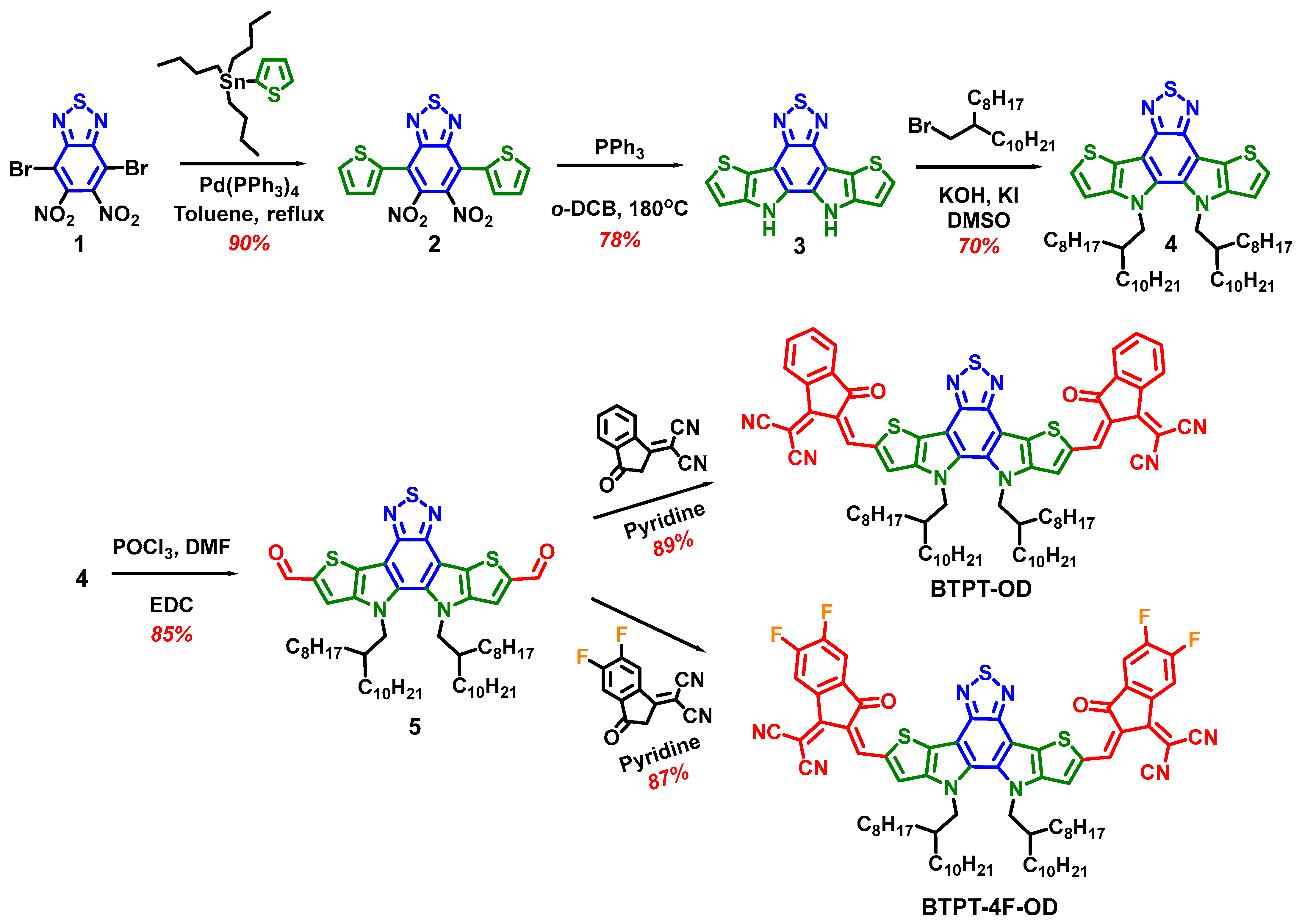
3.1. Synthesis and Characterization

The synthesis of BTPT-OD or BTPT-4F-OD consists of five main steps (Figure 1). First, 5,6-dinitro-4,7-di(2-thienyl)-2,1,3-benzothiadiazole (2) was prepared through the Stille cross-coupling reaction between tributyl(2-thienyl) stannane and 4,7-dibromo-5,6-dinitro-2,1,3-benzothiazole (1) in 90% yield. Second, the double intramolecular Cadogan reductive cyclization of 2 gave rise to 10,11-dihydro[1,2,5]thiadiazolo[3,4-e]thieno[3,2-b]thieno[2′,3′:4,5]pyrrolo[3,2-g]indole (3) in 78% yield. The next step involved the preparation of 10,11-di(2-octyldodecyl)[1,2,5]thiadiazolo [3,4-e]thieno[3,2-b]thieno[2′,3′:4,5]pyrrolo-[3,2-g]indole (4) via N-alkylation of 3 with 1-bromo-2-octyldodecyl in 70% yield. The Wilsmeyer-Haak formylation of 4 led to 10,11-bis(2-octyldodecyl)-10,11-dihydro-[1,2,5]thiadiazolo[3,4-e]thieno[2′,3′:4,5] pyrrolo[3,2-g]thieno[3,2-b]indole-2,8-dicarbaldehyde (5) in 90% yield. The synthesis of the target BTPT-OD and BTPT-4F-OD was carried out by Knoevenagel condensation between dicarbaldehyde 5 and indan-1-one-3-dicyanvinyl or 5,6-difluorindan-1-one-3-dicyanvinyl in high yields 89% and 87%, respectively.
The total reaction yields of BTPT-OD and BTPT-4F-OD were found to be rather high, 37.2% and 36.3%, respectively. However, it is noteworthy that 4 additional steps should be carried out to prepare 5,6-difluorindan-1-one-3-dicyanvinyl [37], which makes the synthesis of BTPT-4F-OD more labor-intensive and significantly decreases the total yield.
BTPT-OD and BTPT-4F-OD showed good solubility in many organic solvents such as THF, methylene chloride, chloroform, or toluene at room temperature. The detailed synthetic procedures and characterization data for BTPT-OD and BTPT-4F-OD as well as all precursors can be found in the Electronic Supplementary Information (ESI).

3.2. Optical and Electrochemical Properties

The optical properties of the molecules synthesized were investigated by UV–vis absorption spectroscopy in diluted CHCl3 solutions (10−6 M) and thin films (Figure 2a and Table 1). The compounds showed rather similar shapes of the absorption spectra: the bands at the high-energy region (300–420 nm) usually ascribed to π–π* transitions and the intensive bands at 620–840 nm usually ascribed to the ICT [40,41] or with a mixed character [42]. BTPT-4F-OD has red-shifted absorption spectra as compared to BTPT-OD due to a narrower electrochemical bandgap as discussed below. The absorption spectra of the thin films were significantly shifted to the long-wavelength region and broadened for both compounds in comparison to their spectra in the solutions.
The highest occupied molecular orbital (HOMO) and the lowest unoccupied molecular orbital (LUMO) energies were calculated from the oxidation and reduction potentials measured by cyclic voltammetry (CV) (see Figure 2b,c). The molecules have close HOMO energies (Table 1), since their electron-donating groups are the same. In contrast, the type of terminal electron-withdrawing groups has a pronounced impact on the LUMO energy. The introduction of fluorine atoms into the structure contributed to the shift of reduction potentials to the positive region and thus the LUMO energy was reduced for BTPT-4F-OD (−3.94 eV) as compared to its fluorine-free analog—BTPT-OD (−3.80 eV). The electrochemical bandgap for BTPT-OD and BTPT-4F-OD was calculated to be 2.02 eV and 1.91 eV, respectively.

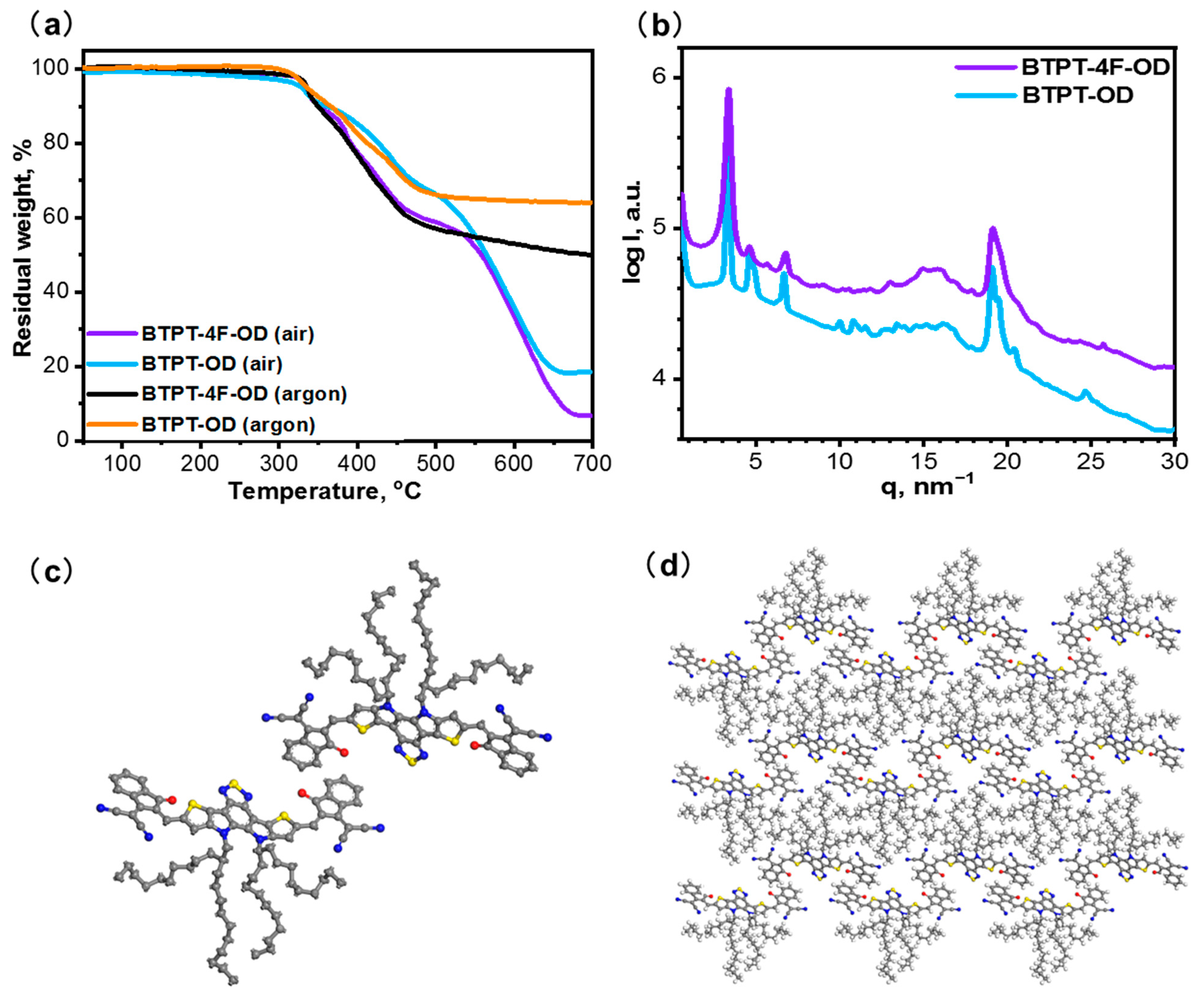
3.3. Thermal and Structural Properties

The thermal and thermo-oxidative stability of BTPT-OD and BTPT-4F-OD molecules were investigated by thermogravimetric analysis (TGA) and the data are summarized in Figure 3a. The compounds showed high stability both in air and under an argon atmosphere with decomposition temperatures above 320° (calculated for 5% weight loss) without any correlation to the molecular structure.
The phase behavior of the novel NFAs was investigated by differential scanning calorimetry (DSC). Analysis of the DSC thermograms showed that the DSC method is non-informative for this type of compound, since the phase transitions of the molecules lie at the same temperature region as the thermal destruction processes.
To investigate crystallinity, the 2D wide-angle (WAXS) analysis of the BTPT-OD and BTPT-4F-OD samples was performed at room temperature, the results of which are shown in Figure 3b. Both samples demonstrated a set of sharp reflections indicating a crystallinity degree of around 50%. The peaks themselves are much narrower for the BTPT-OD sample, which leads to an increase in the crystallite size up to 25 nm as compared to 10 nm for the BTPT-4F-OD sample. Indexation followed by Pawley refinement yielded similar monoclinic cells P2 symmetry with the following parameters: a = 31.4 Å, b = 5.1 Å, c = 24.0 Å, β = 87.5° for BTPT-OD and a = 26.7 Å, b = 4.99 Å, c = 25.1 Å, β = 87.3° for BTPT-4F-OD. The number of molecules per crystal cell equals 2 for both cases. The cell volumes and the angles are almost identical, and the low b value suggests that π-π stacking occurs along the 0k0 planes. Therefore, the molecules are located flatwise in the ac plane. This assumption was confirmed by the Reflex solve processed in the Biovia Material Studio software package. The model obtained by the parallel tempting balancing the Rwp value of the simulated diffraction pattern and the VdW close contacts energy is presented in Figure 3c.

3.4. Photovoltaic Properties

To obtain a clearer understanding of the difference in photovoltaic performance between BTPT-4F-OD and BTPT-OD non-fullerene acceptors, we blended them with a PM6 donor to prepare a bulk heterojunction (BHJ) photovoltaic active layer system. The overall device structure adopts the traditional forward structure of glass/indium tin oxide (ITO)/poly(3,4-ethylenedioxythiophene): poly(styrenesulfonate)(PEDOT:PSS)/PM6:BTPT-4F-OD or PM6:BTPT-OD/PNDIT-F3N/Ag (Figure 4a).
The optimized devices based on PM6:BTPT-4F-OD and PM6:BTPT-OD were obtained under similar processing conditions, which were provided in Table 2. The relevant current density-voltage (J-V) characteristics of the corresponding devices are shown in Figure 4b. The devices based on PM6:BTPT-4F-OD showed a VOC of 0.824 V, a JSC of 8.16 mA/cm2, and a FF of 36.9%, delivering a PCE of 2.48%. The PM6:BTPT-OD devices exhibited an elevated PCE of 4.30% with a high VOC of 0.952 V, an increased JSC of 9.86 mA/cm2, and a FF of 43.3%. The corresponding external quantum response efficiency is shown in Figure 4c. It can be seen that the PM6:BTPT-OD system has a stronger response degree between 350 and 750 nm in the visible region, and the highest external quantum efficiency (EQE) value is close to 45%, while the PM6:BTPT-4F-OD system response range is concentrated between 350 and 800 nm, with a wider EQE response, but its level is much weaker than that of the BTPT-OD system, with a maximum value of only 36%. By analyzing the absorption spectra of PM6, BTPT-4F-OD, and BTPT-OD, it can be found that the maximum absorption peak of BTPT-4F-OD is at 762 nm, with a shoulder at 692 nm. However, BTPT-OD has bluer absorption with the shoulders at 673 nm and the absorption maxima at 734 nm. In addition, it was found that the PM6:BTPT-OD system had a higher light absorption intensity by testing the absorption coefficient of the binary films (Figure 4d). All these results indicate that BTPT-OD had better photovoltaic performance, which could also explain the higher JSC and PCE of the PM6:BTPT-OD system.
To elucidate the exciton dynamics and charge transfer dynamics in these active layers, photoluminescence (PL) quenching experiments were performed. The PL spectra of PM6 pure film, PM6:BTPT-4F-OD, and PM6:BTPT-OD blend films are depicted in Figure 5a. It can be seen that PM6 exhibits a strong fluorescence effect at the excitation wavelength of 532 nm. When blended with BTPT-4F-OD, the PL quenching efficiency of its excitons is 65.9%, while the system blended with BTPT-OD has an increased quenching efficiency of 79.3%. This indicates that the BTPT-OD system has better exciton use efficiency. In addition, we analyze the kinetic process of excitons from the maps of saturation current and effective bias. The saturation current is the difference between the photocurrent and the dark current. The effective bias voltage is equal to V0 minus Va. V0 represents the voltage when the saturation current is 0, and Va is the applied bias voltage. The exciton dissociation efficiency (ηdiss) of the devices can be calculated by the Jph/Jsat values under short-circuit conditions, PM6:BTPT-OD-based devices displayed much higher ηdiss than PM6:BTPT-4F-OD-based devices (82.9% vs. 70.5%).
To monitor the charge transport ability of the system, the mobility of the system was measured using the space-charge-limited-current (SCLC) method. The electron mobility and hole mobility of PM6:BTPT-4F-OD is 3.52 × 10⁻⁴ and 1.94 × 10⁻⁴ cm2V−1s−1, respectively, while that of the PM6:BTPT-OD system is 4.39 × 10⁻⁴ and 2.86 × 10⁻⁴ cm2V−1s−1. It can be seen that the latter not only has greater charge mobility, but also possess more balanced transport mobility, which is beneficial to increase the JSC of the device and achieving higher PCE (Table 3). To further clarify the extinct changes in the JSC and FF, the charge recombination was de-fined by measurement of JSC and VOC changes under various light intensities (P) from 100 to 5 mW cm−2. The relationship between JSC and Plight can be summarized as a power-law equation of JSC∝Pα, which is employed to analyze the bimolecular recombination in OSC devices. The variation of VOC relative to light intensity is represented by the slope n of nkT/q (Figure 5d,e). Compared with the PM6:BTPT-4F-OD system, PM6:BTPT-OD has a higher α value (0.975 vs. 0.885) and a smaller n value (1.18 vs. 1.24), indicating that the BTPT-OD system has less bimolecular recombination and trap-assisted recombination. Additionally, as demonstrated in Figure 5f,g, transient photocurrent (TPC) and transient photovoltage (TPV) were determined to evaluate the charge extraction time (τ1) and charge carrier lifetimes (τ2) in the corresponding devices. It can be seen that the τ1 and τ2 of the BTPT-OD system are 0.29 us and 5.3 us, respectively, while the τ1 and τ2 of the BTPT-4F-OD system are only 0.97 us and 3.0 us, which indicates that the former has faster charge extraction time and longer carrier lifetime, supporting the significant enhancement of JSC and FF.
To monitor the surface morphology and crystallization properties of the active layer, AFM characterization was performed for both systems. Root mean square (RMS) values of 1.21 nm and 0.77 nm were obtained for the PM6:BTPT-4F-OD (Figure 6a,b) and the PM6:BTPT-OD (Figure 6c,d) systems, respectively. The observed differences in sample roughness suggested that the PM6:BTPT-OD system might have a more suitable distribution of donor and acceptor phases, facilitating a better interpenetrating network structure and, consequently, an adequate dissociation and efficient transport of excitons. Perhaps the improved microscopic morphology of the PM6:BTPT-OD system led to a higher PCE.

4. Conclusions

In conclusion, we successfully synthesized two novel non-fullerene acceptors BTPT-OD and BTPT-4F-OD with the simplest fused structures among Y-like NFAs. The acceptor molecules obtained have efficient light absorption in the visible and near-IR spectral range (700–950 nm), low LUMO energy levels (below −3.80 eV), high thermal stability (above 300 °C), as well as the absence of phase transitions in the device operating temperature range. The higher degree of photoresponsiveness, better charge dynamics performance, more rational exciton transport paths, and more balanced charge transport characteristics are the reasons why PM6:BTPT-OD exhibits better photovoltaic performance than PM6:BTPT-4F-OD. Despite the moderate PCEs obtained for OSCs based on novel NFAs, our work demonstrates that the choice of terminal acceptor group is of high importance for the molecular design of Y-like NFAs. Although a higher performance in OSCs was expected for the BTPT-4F-OD with 5,6-difluorindan-1-one-3-dicyanvinyl terminal acceptor group due to the red-shifted light absorption and lower LUMO energy, it exhibited almost two times lower PCE in devices as compared to its counterpart BTPT-OD with a much simpler acceptor group. We believe that further molecular design of the similar simple NFAs taking into account not only the type of terminal acceptor group but also side alkyl chain engineering will boost the performance of the OSCs.

Supplementary Materials

The following supporting information can be downloaded at: https://www.mdpi.com/article/10.3390/en16083443/s1, Supplementary Information (NMR, and OSCs data) to this article can be found online.

Author Contributions

Conceptualization and Methodology, Y.N.L., J.M. and S.A.P.; Investigation, A.V.B. and J.W.; Resources and Investigation, E.D.P., D.O.B. and I.V.D.; Writing—Original Draft Preparation, E.D.P. and J.W.; Writing—Review and Editing, Y.N.L., E.D.P., J.W., J.M., A.V.B. and S.A.P.; Supervision, Y.N.L. and J.M.; Project Administration, J.M. and S.A.P. All authors have read and agreed to the published version of the manuscript.

Funding

The work on the synthesis and characterization of BTPT-OD and BTPT-4F-OD was financially supported by the Russian Science Foundation (21-43-00051). The work on OSCs was financially supported by the National Natural Science Foundation of China (NSFC) (Grant No. 52061135206). The NMR spectra were recorded using the equipment of the Collaborative Access Center ”Center for Polymer Research” of Enikolopov Institute of Synthetic Polymeric Materials of the Russian Academy of Sciences under financial support from the Ministry of Science and Higher Education of the Russian Federation (topic FFSM-2021-0005).

Data Availability Statement

Data are included within the manuscript.

Acknowledgments

The authors acknowledge O.A. Maloshitskaya for recording MALDI-TOF spectra, S.M. Peregudova for CV experiments, and N.M. Surin for the recording of absorption spectra.

Conflicts of Interest

The authors declare no conflict of interest.

References

  1. Zhang, G.; Zhao, J.; Chow, P.C.Y.; Jiang, K.; Zhang, J.; Zhu, Z.; Yan, H.; Huang, F.; Yan, H. Non-fullerene Acceptor Molecules for Bulk Heterojunction Organic Solar Cells. Chem. Rev. 2018, 118, 3447–3507. [Google Scholar] [CrossRef] [PubMed]
  2. Riede, M.; Spoltore, D.; Leo, K. Organic Solar Cells—The Path to Commercial Success. Adv. Energy Mater. 2021, 11, 2002653. [Google Scholar] [CrossRef]
  3. Mahmood, A.; Wang, J.L. Machine Learning for High Performance Organic Solar Cells: Current Scenario and Future Prospects. Energy Environ. Sci. 2021, 14, 90–105. [Google Scholar] [CrossRef]
  4. Moser, M.; Wadsworth, A.; Gasparini, N.; McCulloch, I. Challenges to the Success of Commercial Organic Photovoltaic Products. Adv. Energy Mater. 2021, 11, 2100056. [Google Scholar] [CrossRef]
  5. Kini, G.P.; Jeon, S.J.; Moon, D.K. Latest Progress on Photoabsorbent Materials for Multifunctional Semitransparent Organic Solar Cells. Adv. Funct. Mater. 2021, 31, 2007931. [Google Scholar] [CrossRef]
  6. Sun, R.; Wu, Y.; Yang, X.; Gao, Y.; Chen, Z.; Li, K.; Qiao, J.; Wang, T.; Guo, J.; Liu, C.; et al. Single-Junction Organic Solar Cells with 19.17% Efficiency Enabled by Introducing One Asymmetric Guest Acceptor. Adv. Mater. 2022, 34, 2110147. [Google Scholar] [CrossRef] [PubMed]
  7. Cui, Y.; Xu, Y.; Yao, H.; Bi, P.; Hong, L.; Zhang, J.; Zu, Y.; Zhang, T.; Qin, J.; Ren, J.; et al. Single-Junction Organic Photovoltaic Cell with 19% Efficiency. Adv. Mater. 2021, 33, 2102420. [Google Scholar] [CrossRef] [PubMed]
  8. Bi, P.; Zhang, S.; Chen, Z.; Xu, Y.; Cui, Y.; Zhang, T.; Ren, J.; Qin, J.; Hong, L.; Hao, X.; et al. Reduced Non-Radiative Charge Recombination Enables Organic Photovoltaic Cell Approaching 19% Efficiency. Joule 2021, 5, 2408–2419. [Google Scholar] [CrossRef]
  9. Zhu, L.; Zhang, M.; Xu, J.; Li, C.; Yan, J.; Zhou, G.; Zhong, W.; Hao, T.; Song, J.; Xue, X.; et al. Single-Junction Organic Solar Cells with over 19% Efficiency Enabled by a Refined Double-Fibril Network Morphology. Nat. Mater. 2022, 21, 656–663. [Google Scholar] [CrossRef]
  10. Chiristina, E.N.; Rahayu, S.U.; Tubtimtae, A.; Shi, J.-B.; Lee, M.-W. Rare-Earth-Incorporated Ternary Ce x Cd 1−x S Quantum Dot-Sensitized Solar Cells. RSC Adv. 2022, 12, 31093–31101. [Google Scholar] [CrossRef]
  11. Sun, S.; Xu, M.; Zhang, Y.; Liu, R.; Wang, X.; Zhang, L.; Fang, Y.; Wang, P. Study of Molybdenum Oxide Optimized Hole Carrier Transport in Perovskite Solar Cells. Org. Electron. 2023, 113, 106697. [Google Scholar] [CrossRef]
  12. Tai, Q.; Yan, F. Emerging Semitransparent Solar Cells: Materials and Device Design. Adv. Mater. 2017, 29, 1700192. [Google Scholar] [CrossRef] [PubMed]
  13. Guo, F.; Ameri, T.; Forberich, K.; Brabec, C.J. Semitransparent Polymer Solar Cells. Polym. Int. 2013, 62, 1408–1412. [Google Scholar] [CrossRef]
  14. Dai, S.; Zhan, X. Nonfullerene Acceptors for Semitransparent Organic Solar Cells. Adv. Energy Mater. 2018, 8, 1800002. [Google Scholar] [CrossRef]
  15. Li, Y.; Xu, G.; Cui, C.; Li, Y. Flexible and Semitransparent Organic Solar Cells. Adv. Energy Mater. 2018, 8, 1701791. [Google Scholar] [CrossRef]
  16. Landerer, D.; Bahro, D.; Röhm, H.; Koppitz, M.; Mertens, A.; Manger, F.; Denk, F.; Heidinger, M.; Windmann, T.; Colsmann, A. Solar Glasses: A Case Study on Semitransparent Organic Solar Cells for Self-Powered, Smart, Wearable Devices. Energy Technol. 2017, 5, 1936–1945. [Google Scholar] [CrossRef]
  17. Hollingsworth, J.A.; Ravishankar, E.; O’Connor, B.; Johnson, J.X.; DeCarolis, J.F. Environmental and Economic Impacts of Solar-Powered Integrated Greenhouses. J. Ind. Ecol. 2020, 24, 234–247. [Google Scholar] [CrossRef] [Green Version]
  18. Sumaiya, S.; Kardel, K.; El-Shahat, A. Organic Solar Cell by Inkjet Printing—An Overview. Technologies 2017, 5, 53. [Google Scholar] [CrossRef] [Green Version]
  19. Xue, P.; Cheng, P.; Han, R.P.S.; Zhan, X. Printing Fabrication of Large-Area Non-Fullerene Organic Solar Cells. Mater. Horizons 2022, 9, 194–219. [Google Scholar] [CrossRef]
  20. Burlingame, Q.; Huang, X.; Liu, X.; Jeong, C.; Coburn, C.; Forrest, S.R. Intrinsically Stable Organic Solar Cells under High-Intensity Illumination. Nature 2019, 573, 394–397. [Google Scholar] [CrossRef]
  21. Leonard, N.G.; Lee, S.W.; Chang, D.W.; Hodgkiss, J.M.; Vak, D. Organic Photovoltaics’ New Renaissance: Advances Toward Roll-to-Roll Manufacturing of Non-Fullerene Acceptor Organic Photovoltaics. Adv. Mater. Technol. 2022, 7, 2101556. [Google Scholar] [CrossRef]
  22. Peng, C.; Huang, Y.; Wu, Z. Building-integrated photovoltaics (BIPV) in architectural design in China. Energy Build. 2011, 43, 3592–3598. [Google Scholar] [CrossRef]
  23. Biyik, E.; Araz, M.; Hepbasli, A.; Shahrestani, M.; Yao, R.; Shao, L.; Essah, E.; Oliveira, A.C.; del Caño, T.; Rico, E.; et al. A Key Review of Building Integrated Photovoltaic (BIPV) Systems. Eng. Sci. Technol. Int. J. 2017, 20, 833–858. [Google Scholar] [CrossRef]
  24. Fan, B.; Zhang, D.; Li, M.; Zhong, W.; Zeng, Z.; Ying, L.; Huang, F.; Cao, Y. Achieving over 16% efficiency for single-junction organic solar cells. Sci. China Chem. 2019, 62, 746–752. [Google Scholar] [CrossRef]
  25. Zhao, J.J.; Yao, C.; Ali, M.U.; Miao, J.; Meng, H. Recent Advances in High-performance Organic Solar Cells Enabled by Acceptor-Donor-Acceptor-Donor-Acceptor (A-DA’D-A) Type Acceptors. Mater. Chem. Front. 2020, 4, 3487–3504. [Google Scholar] [CrossRef]
  26. Yuan, J.; Zhang, Y.; Zhou, L.; Zhang, G.; Yip, H.-L.; Lau, T.-K.; Zou, Y.; Zhu, C.; Peng, H.; Johnson, P.A.; et al. Single-Junction Organic Solar Cell with over 15% Efficiency Using Fused-Ring Acceptor with Electron-Deficient Core. Joule 2019, 3, 1140–1151. [Google Scholar] [CrossRef]
  27. Luo, D.; Jang, W.; Babu, D.D.; Kim, M.S.; Wang, D.H.; Kyaw, A.K.K. Recent progress in organic solar cells based on non-fullerene acceptors: Materials to devices. J. Mater. Chem. A 2022, 10, 3255–3295. [Google Scholar] [CrossRef]
  28. He, Q.; Ufimkin, P.; Aniés, F.; Hu, X.; Kafourou, P.; Rimmele, M.; Rapley, C.L.; Ding, B. Molecular engineering of Y-series acceptors for nonfullerene organic solar cells. SusMat 2022, 2, 591–606. [Google Scholar] [CrossRef]
  29. Zhang, J.; Xiang, Y.; Zheng, S. From Y6 to BTPT-4F: A theoretical insight into the influence of the individual change of fused-ring skeleton length or side alkyl chains on molecular arrangements and electron mobility. New J. Chem. 2021, 45, 12247–12259. [Google Scholar] [CrossRef]
  30. Ming, R.; Gao, J.; Gao, W.; Ning, W.; Luo, Z.; Zhang, F.; Yang, C. Benzo[c][1,2,5]thiadiazole-Fused Pentacyclic Small Molecule Acceptors for Organic Solar Cells. Dyes Pigm. 2020, 185, 108970. [Google Scholar] [CrossRef]
  31. Qiu, W.; Zheng, S. Designing and Screening High-Performance Non-Fullerene Acceptors: A Theoretical Exploration of Modified Y6. Sol. Rrl 2022, 5, 2100023. [Google Scholar] [CrossRef]
  32. Murugan, P.; Hu, T.; Hu, X.; Chen, Y. Fused ring A–DA′D–A (Y-series) non-fullerene acceptors: Recent developments and design strategies for organic photovoltaics. J. Mater. Chem. A 2022, 10, 17968–17987. [Google Scholar] [CrossRef]
  33. Wang, J.; Xue, P.; Jiang, Y.; Huo, Y.; Zhan, X. The principles, design and applications of fused-ring electron acceptors. Nat. Rev. Chem. 2022, 6, 614–634. [Google Scholar] [CrossRef]
  34. Uno, T.; Takagi, K.; Tomoeda, M. Synthesis of Bisfurazanobenzo-2, 1, 3-thiadiazole and Related Compounds. Chem. Pharm. Bull. 1980, 28, 909–1912. [Google Scholar] [CrossRef] [Green Version]
  35. Pu, S.; Zheng, C.; Sun, Q.; Liua, G.; Fan, C. Enhancement of cyclization quantum yields of perfluorodiarylethenes via weak intramolecular interactions. Chem. Commun. 2013, 48, 8036–8038. [Google Scholar] [CrossRef]
  36. Uddin, M.A.; Lee, T.H.; Xu, S.; Park, S.Y.; Kim, T.; Song, S.; Nguyen, T.L.; Ko, S.J.; Hwang, S.; Kim, J.Y.; et al. Interplay of Intramolecular Noncovalent Coulomb Interactions for Semicrystalline Photovoltaic Polymers. Chem. Mater. 2015, 27, 5997–6007. [Google Scholar] [CrossRef]
  37. Yao, H.; Cui, Y.; Yu, R.; Gao, B.; Zhang, H.; Hou, J. Design, Synthesis, and Photovoltaic Characterization of a Small Molecular Acceptor with an Ultra-Narrow Band Gap Angew. Chem. Int. Ed. 2017, 56, 3045–3049. [Google Scholar] [CrossRef]
  38. Ponomarenko, S.A.; Rasulova, N.N.; Luponosov, Y.N.; Surin, N.M.; Buzin, M.I.; Leshchiner, I.; Peregudova, S.M.; Muzafarov, A.M. Bithiophenesilane-Based Dendronized Polymers: Facile Synthesis and Properties of Novel Highly Branched Organosilicon Macromolecular Structures. Macromolecules 2012, 45, 2014–2024. [Google Scholar] [CrossRef]
  39. Cardona, C.M.; Li, W.; Kaifer, A.E.; Stockdale, D.; Bazan, G.C. Electrochemical Considerations for Determining Absolute Frontier Orbital Energy Levels of Conjugated Polymers for Solar Cell Applications. Adv. Mater. 2011, 23, 2367–2371. [Google Scholar] [CrossRef]
  40. Roncali, J.; Leriche, P.; Cravino, A. From one- to three-dimensional organic semiconductors: In search of the organic silicon? Adv. Mater. 2007, 19, 2045–2060. [Google Scholar] [CrossRef] [Green Version]
  41. Kozlov, O.V.; Luponosov, Y.N.; Ponomarenko, S.A.; Kausch-Busies, N.; Paraschuk, D.Y.; Olivier, Y.; Beljonne, D.; Cornil, J.; Pshenichnikov, M.S. Ultrafast charge generation pathways in photovoltaic blends based on novel star-shaped conjugated molecules. Adv. Energy Mater. 2014, 5, 1401657. [Google Scholar] [CrossRef]
  42. Roncali, J.; Grosu, I. The dawn of single material organic solar cells. Adv. Sci. 2019, 6, 1801026. [Google Scholar] [CrossRef] [PubMed] [Green Version]
Figure 1. Synthesis of BTPT-OD and BTPT-4F-OD.
Energies 16 03443 g001
Figure 2. (a) UV–vis spectra in the chloroform solutions and thin films and; (b) CV curves and; (c) energy level diagram of the boundary orbitals of BTPT-OD and BTPT-4F-OD.
Energies 16 03443 g002
Figure 3. (a) Thermogravimetric analysis data in air and in an inert atmosphere and; (b) X-ray scattering curves for the BTPT-OD and BTPT-4F-OD and; (c) molecular packing of the BTPT-OD molecule into the monoclinic crystal cell X-ray scattering patterns in small and; (d) the molecular packing of the BTPT-OD to the 3 × 3 crystal lattice; hydrogen atoms were removed for visibility.
Energies 16 03443 g003
Figure 4. (a) Schematic device structure; (b) J-V characteristics for devices based on PM6: BTPT-4F-OD and PM6: BTPT-OD blends; (c) Corresponding EQE spectra of PM6: BTPT-4F-OD and PM6: BTPT-OD-based devices; (d) Absorption coefficient spectra of PM6: BTPT-4F-OD and PM6: BTPT-OD films.
Energies 16 03443 g004
Figure 5. (a) Steady-state fluorescence patterns of PM6, PM6:BTPT-4F-OD, and PM6:BTPT-OD films; (b) Jph versus Veff curves; (c) electron and hole mobility; (d) JSC versus Plight; (e) VOC versus Plight; (f) transient photocurrent, and; (g) transient photovoltage plots of PM6:BTPT-4F-OD and PM6:BTPT-OD devices.
Energies 16 03443 g005
Figure 6. The AFM and relevant 3D images of: (a,b) PM6: BTPT-4F-OD and (c,d) PM6: BTPT-OD.
Energies 16 03443 g006
Table 1. Optical and electrochemical data of BTPT-OD and BTPT-4F-OD.
λmax a, nmε b 105 (L × mol−1 × cm−1)λmax c, nmφox/HOMO d, eVφred/LUMO d, eVEg d, eV
BTPT-OD6882.107341.42/−5.82−0.60/−3.802.02
BTPT-4F-OD7112.057621.45/−5.85−0.46/−3.941.91
a λmax—absorption maximum for CHCl3 solutions; b molar extinction coefficient in the absorption spectra maximum measured for CHCl3 solutions; c λmax—absorption maximum for the thin films; d calculated from the CV experiments.
Table 2. Specific device performance of the binary devices under the processing condition of AM 1.5G (100 mW/cm2).
Active LayerVOC (V)JSC (Jcalc) a
(mA/cm2)
FF (%)PCE
(%, PCEavg b)
PM6:BTPT-4F-OD0.8248.16 (7.84)36.92.48 (2.32 ± 0.13)
PM6:BTPT-OD0.9529.86 (9.70)43.34.30 (4.19 ± 0.12)
a The Jcalc calculated from the EQE spectrum. b The average values with the standard deviation were obtained from 10 devices.
Table 3. Parameters of electron mobility and hole mobility of PM6:BTPT-4F-OD and PM6: BTPT-OD devices).
Deviceμe (×10−4 cm2 V−1 s−1)μh (×10−4 cm2 V−1 s−1)μe/μh
PM6:BTPT-4F-OD3.52 ± 0.251.94 ± 0.311.81
PM6:BTPT-OD4.39 ± 0.272.86 ± 0.281.53
Disclaimer/Publisher’s Note: The statements, opinions and data contained in all publications are solely those of the individual author(s) and contributor(s) and not of MDPI and/or the editor(s). MDPI and/or the editor(s) disclaim responsibility for any injury to people or property resulting from any ideas, methods, instructions or products referred to in the content.

