1. Introduction
Solar energy is one way to replace traditional energy, and improving its conversion efficiency is a key research field. Photovoltaic power generation and solar thermal power generation are two widely studied conversion technologies in this field, but their conversion efficiencies are limited by the inherent characteristics of their own structures and materials [
1,
2]. The direct combination of a photovoltaic system and a solar heat converter has been found to achieve a theoretical efficiency of more than 60% [
3]. However, the two technologies conflict in operating temperature, which makes them difficult to implement in practice [
4,
5].
In order to solve the above problems and improve solar energy conversion, it is necessary to combine the photovoltaic effect with thermionic emission. In 2004, Smestad proved that both light and heat from solar energy can be converted into electricity at the same time through illustrative experiments using vacuum diodes [
6]. In 2010, Schwede et al. proposed the photon-enhanced thermionic emission (PETE) conversion concept in order to combine the two conversion mechanisms into a single physical process [
7]. Using a structure similar to the vacuum thermionic energy converter (VTEC) and using a semiconductor cathode, the PETE converter could effectively take advantage of the thermal loss caused by low-energy photons in the solar spectrum, theoretically breaking the Shockley–Queisser (SQ) limit and achieving an efficiency of over 40% [
7,
8].
Since the PETE theory was proposed, researchers have continually explored the structure of the PETE converter in order to optimize its performance. Segev et al. designed a multistage series solar cell based on PETE, which could achieve an efficiency of 30–40% in isothermal state, and was better than the thermionic converter, which needed to maintain the temperature difference between the anode and the cathode [
9]. They also demonstrate that the ultimate efficiency of single-bandgap PETE converters in the isothermal state is still limited by the SQ limit, which can be exceeded by nonisothermal operation [
10]. Wang et al. explored the limitation of the space charge effect on the PETE converter and found that the conversion efficiency can be effectively improved with a suitable interelectrode space [
11,
12]. Qiu et al. combined the PETE converter with a Stirling heat engine and modeled the hybrid system with full consideration of optical, electrical, and thermodynamic processes. Through simulation analysis, for 500 solar concentrations, the output power of the hybrid system could reach 162.65 KW/m
2 with a conversion efficiency of 32.77% [
13].
Regarding the selection of cathode materials, previous studies have shown that III–V semiconductors have good PETE properties but are concentrated on GaAs-based materials [
14,
15,
16,
17]. Both GaN and InN have been applied to PETE converter cathodes, while cathodes based on InGaN ternary compounds have not yet been attempted [
7,
18]. The bandgap of InN is 0.7 eV, and that of GaN is 3.4 eV [
19]. The ternary compound InGaN formed by these two compounds can achieve an adjustable bandgap of 0.7–3.4 eV by changing the composition of In, which can cover most of the solar spectra [
20]. Additionally, InGaN is widely studied in the field of high-temperature solar cells. Huang et al. found that InGaN-based solar cells would have a self-cooling effect at high temperatures, which is helpful for improving performance [
21]. Moses et al. explored the performance of InGaN solar cells at high solar concentrations and high temperatures. Through experimental research, for 300 solar concentrations, the conversion efficiency peaked at 623–723 K, and InGaN maintained good stability at high temperature [
22]. In addition, InGaN has a high absorption coefficient and can effectively utilize sunlight [
23]. Based on the above characteristics, InGaN was selected as the cathode for the PETE converter.
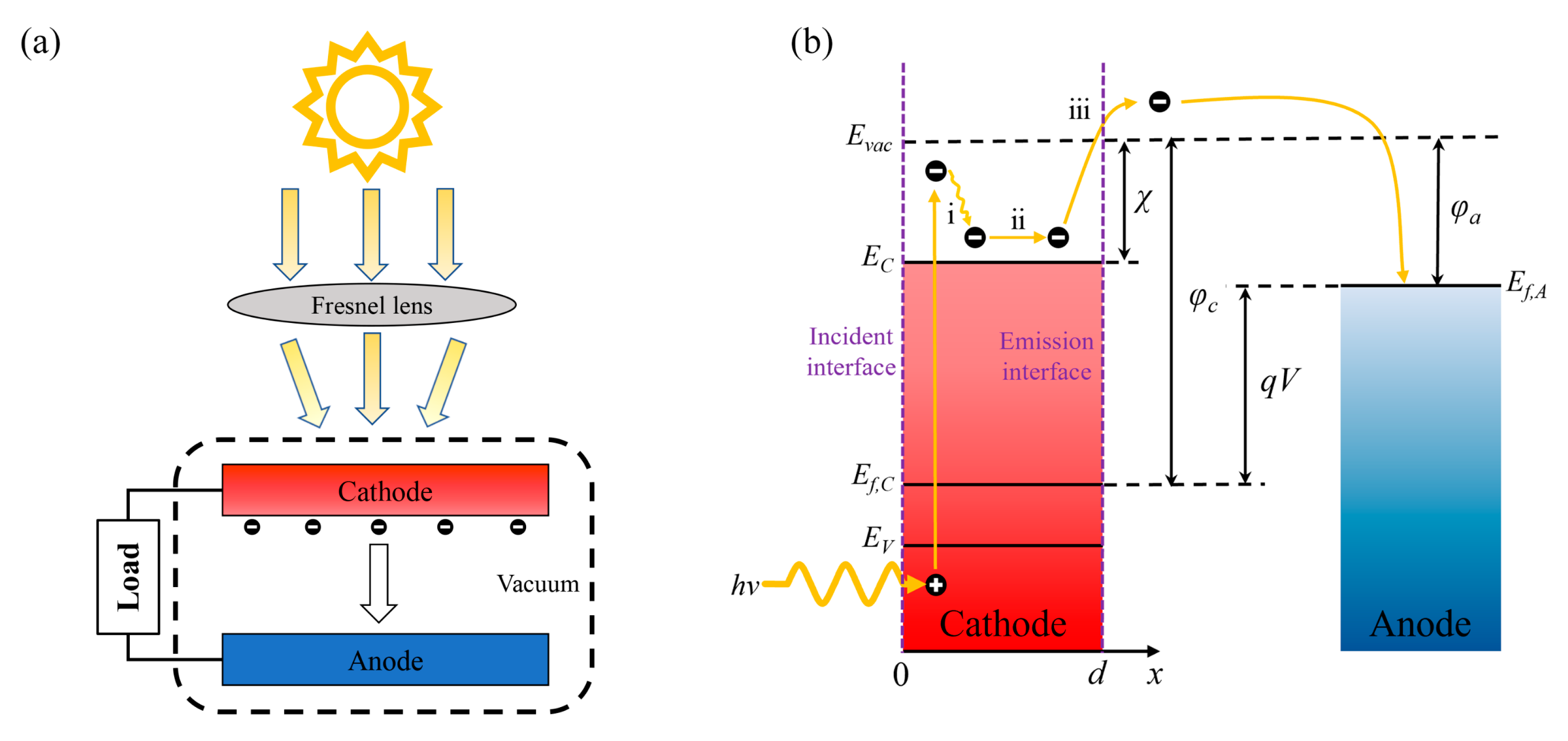
In this study, the structure of a vacuum PETE converter was used to establish the temperature difference between anode and cathode. Based on the one-dimensional steady-state continuity equation, the performance of converters in isothermal and nonisothermal operations was analyzed and compared. In the calculation, we considered the change in the bandgap of the InGaN cathode with temperature and simulated the temperature dependence of excess electron concentration, current density, and conversion efficiency for different cathode electron affinities. In addition, the reason why the open-circuit voltage of the converter was higher than that of the nonisothermal operation is analyzed. We investigate the behavior of the PETE converter under applied bias at different cathode temperatures and further determine the point of maximum conversion efficiency.
3. Results and Analysis
In the simulation, the In composition of the cathode is set as 0.6, and the bandgap is 1.44 eV according to Equation (6), which is within the optimal range of PETE effect and can cover most visible wavelengths of the AM1.5G spectrum [
7]. InGaN materials are usually grown on sapphire or GaN substrates, which have a wide bandgap; thus, the absorption of incident light by the substrates is ignored. The InGaN with high In components is usually thin in thickness. In this study, the cathode thickness was set as 0.2 μm, and the p-type doping concentration was set as 1 × 10
18 cm
−3 [
32,
33,
34]. To simplify the calculation, the diffusion coefficient and the electron lifetime were treated as constants independent of temperature.
Dn = 63.6 cm
2/s corresponds to In
0.6Ga
0.4N, which can be obtained by the formula in [
35]. The electron lifetime of the cathode is 1 ns, so the diffusion length can be obtained by
[
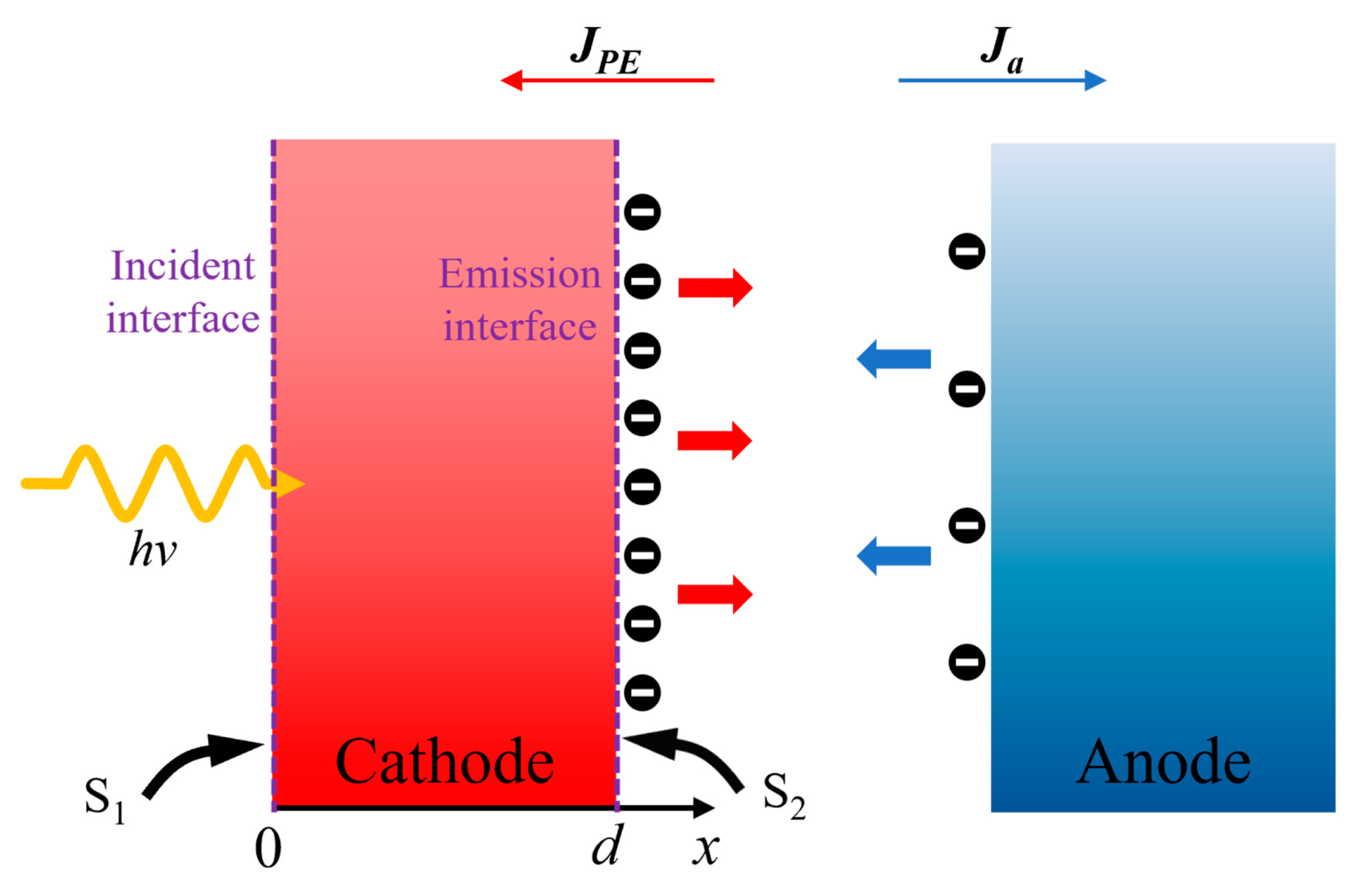
27]. The composite velocity of the incident interface was set as
S1 = 1 × 10
5 cm/s [
36,
37]. For the emission interface, the composite velocity,
S2, can be reduced by passivation treatment and was set to 10
3 cm/s [
38]. The anode was phosphorus-doped diamond, and the work function,
φa, was 0.9 eV [
39]. The AM1.5G solar spectrum was used in the calculation, and the PETE solar converter operated at 1000 solar concentrations (
Psolar = 100 W/cm
2).
The performance of PETE converters based on the In
0.6Ga
0.4N cathode was calculated using the above analytical model. The bandgap of the cathode decreased with increasing temperature; therefore, the electron affinity,
χ, increased from 0.4 eV to keep the cathode work function,
φc, greater than the anode work function,
φa. When the anode and the cathode were isothermal, the variation trend in excess electron concentration,
n(
d), at the emission interface with different electron affinities was as shown in
Figure 3a. There was a slow increase and then a sharp decline in the number of excess electrons. The reason is that at low temperatures, excess electrons do not have enough energy to overcome the electron affinity and accumulate at the emission interface. The heat generated by the rising temperature allows these electrons to overcome the electron affinity and reach the anode in the form of thermionic emission. The number of excess electrons eventually decreases to reach a certain value as the temperature continues to rise, and this value is positively correlated with the electron affinity. This is because as the electron affinity increases, the excess electron concentration becomes greater at the emission interface, and the temperature required to provide more energy for the electron emission is higher. In the case of isothermal cathodes and anodes, the reverse thermal current of the anode increases with increasing temperature, which undoubtedly increases the excess electron concentration of the cathode, making it unable to drop to zero. This effect is particularly significant at electron affinities above 0.4 eV.
Figure 3b shows the photon-enhanced current, thermal current, and photon-enhanced thermal current as functions of temperature at an electron affinity of 0.4 eV. The figure can be simply divided into three regions: the photoelectric emission region, the photon-enhanced thermionic emission region, and the thermoelectric emission region. When the temperature is below 550 K, the PETE converter mainly relies on the photoelectric emission mechanism. The current density starts at zero and then increases rapidly, which corresponds to the accumulation stage and the emission stage in
Figure 3a. Above 950 K, the thermoelectric emission mechanism plays a dominant role. Above 850 K, the thermoelectric emission mechanism plays a dominant role, and the current density rises rapidly for a second time. In the region of 550–850 K, the photoelectric emission tends to saturate and the influence of photon enhancement is greatest, while the thermoelectric emission is obscured at this time, and the current density of the cathode remains constant. By way of a saturated photocurrent boosting the initial current of thermoelectric emission, the PETE mechanism combines the two, which enables the converter to adapt to a wider temperature range and make better use of solar energy.
Figure 3c shows the variation in output current density with temperature under isothermal conditions. The output current densities of the converters operating at different electron affinities show similar trends as in
Figure 3b. There is a phase of slow increase in current density between two rapid increases, that is, the saturation region. According to
Figure 3a, the number of excess electrons that can be emitted decreases with the increase in electron affinity; thus, the saturation current also decreases, and the saturation region is shortened. When the electron affinity exceeds 0.6 eV, the saturation region of the output current density begins to become less obvious, as shown in the inset. The temperature dependence of the current tends to be the thermal current state. At this time, the PETE converter behaves as a thermionic converter. This indicates that the PETE mechanism cannot be fully utilized at high barriers when the converter is isothermal.
Figure 3d shows the variation in conversion efficiency with temperature. With the increase of electron affinity, the maximum conversion efficiency first increases and then decreases. The increment in efficiency is 1.52% as the electron affinity changes from 0.4 eV to 0.5 eV, whereas it is only 0.52% as the electron affinity continues to rise to 0.6 eV. At 0.7 eV, the conversion efficiency drops directly to 17.94%. The reason is that the decrease in saturation current will eventually be greater than the increase in electron affinity. This indicates that there is an optimal range of electron affinities that maximizes the performance of PETE converters under isothermal conditions.
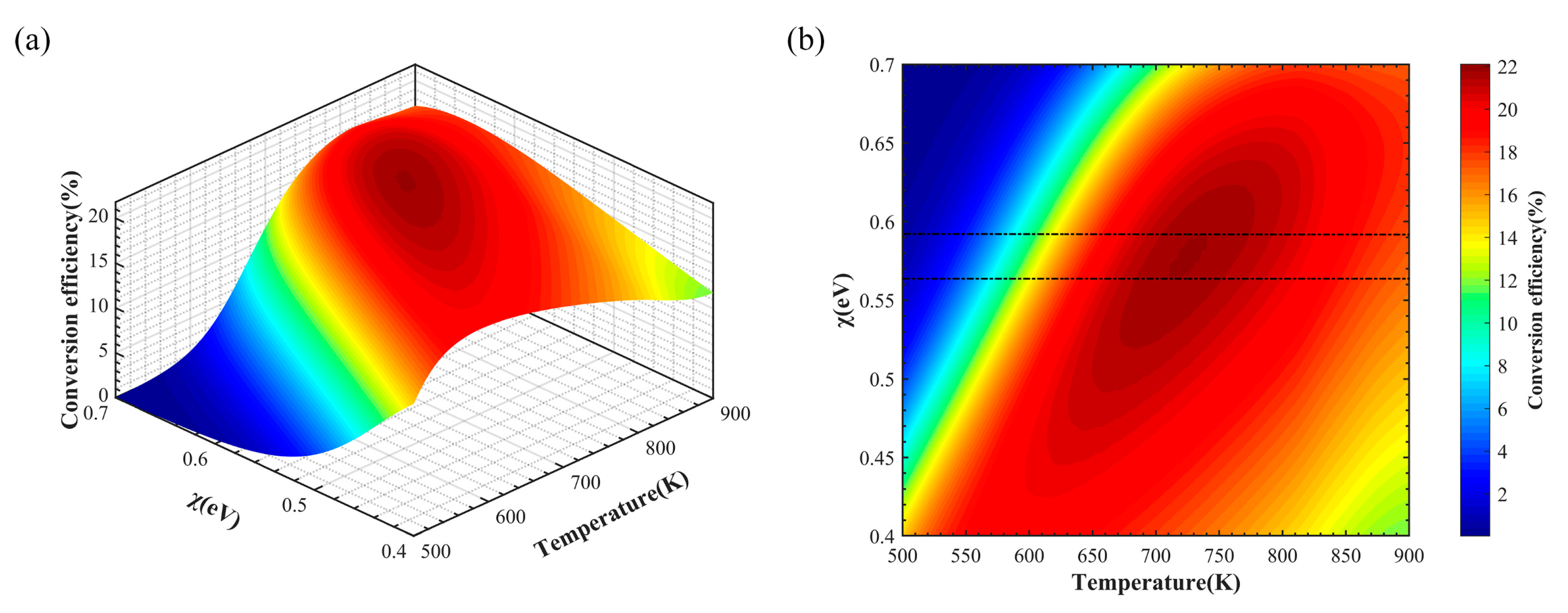
In order to further determine the optimal range of electron affinity and temperature of the PETE solar converter under isothermal conditions, their effects on the conversion efficiency are plotted as shown in
Figure 4a,b. When the electron affinity potential is constant, the conversion efficiency first increases and then decreases with increasing temperature. The same trend holds for a given temperature. Overall, the conversion efficiency is maximized when the electron affinity potential is 0.45–0.52 eV and the operating temperature is 645–705 K. Although the PETE converter can generate a net current under the influence of electron affinity when the cathode and the anode are isothermal, it is still limited by the reverse current caused by the hot anode at high temperatures.
The anode can be cooled by connecting it to an external thermal cycle, and the waste heat can be reused to convert electricity, further improving the conversion efficiency. Therefore, in the following discussion, the anode temperature is set at 500 K, which is the same as the hypothesis in a previous study [
7]. In this case, the cathode temperature increased from 500 K to keep the PETE converter in nonisothermal operation.
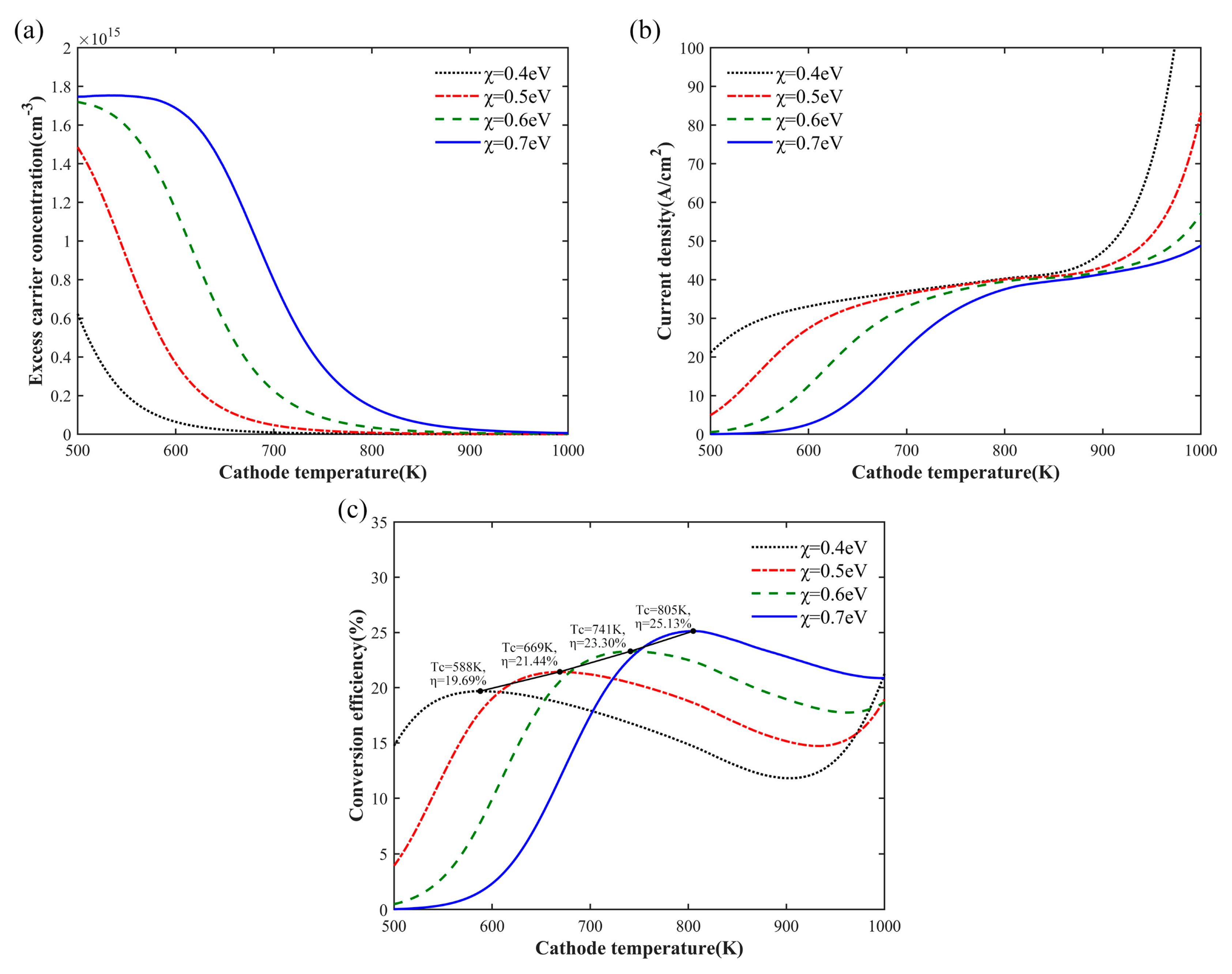
Figure 5a shows the relationship between the excess electron concentration and the cathode temperature. When the electron affinity was 0.4–0.6 eV, the excess electron concentration decreased monotonously with the increase in cathode temperature, and the slow accumulation of electrons in the conduction band of the emission surface could be observed at 0.7 eV. However, unlike the isothermal case, the decline in excess electrons at different electron affinities tended to be consistent in the nonisotherm case. This is because the anode temperature is 500 K, and it can be calculated from Equation (11) that the reverse thermal current without bias is only 0.026 A/cm
2, which has negligible influence on the electron emission. The excess electrons at different affinities are eventually emitted, resulting in an electron concentration of almost zero.
For an anode temperature of 500 K, the output current density with the change in cathode temperature is shown in
Figure 5b. Compared with
Figure 3c, with the increase in electron affinity, the anode maintained a low temperature to avoid deterioration of the saturation current and tended to be the same numerically. At low electron affinity, the output current had a better temperature response, reaching saturation value at lower temperature. However, for an anode work function of 0.9 eV, the decrease in the electron affinity potential affected the cathode work function, resulting in a decrease in the output voltage at zero bias. Therefore, the lower electron affinity was not better for PETE converters.
Figure 5c depicts the relationship between the conversion efficiency and the cathode temperature. For the given electron affinity, the conversion efficiency reached the maximum when the current entered the saturation region and then began to decline. This can be explained as the difference between the work functions of the cathode and the anode decreases due to the influence of temperature on the bandgap; this decrease is greater than the increase in current. However, when thermoelectric emission was dominant, the current increased exponentially, and the effect of the drop in the difference of the work function was completely outweighed, causing the conversion efficiency to grow again. When the electron affinity was 0.6 eV, the maximum conversion efficiency exceeded the ultimate efficiency of the isothermal state. According to
Figure 3d and
Figure 5c, at 0.7 eV, the optimal operating temperature of the nonisothermal converter was reduced by 10 K compared to the isothermal state. This indicates that the temperature response of cathodes with high electron affinity is affected by the increase in anode temperature. With the increase in electron affinity, the maximum conversion efficiency increased linearly, and the cathode needed to operate at a higher temperature. The efficiency of the converter was numerically predicted to exceed 30% at the electron affinity of 1 eV, but the optimum operating temperature was over 1000 K.
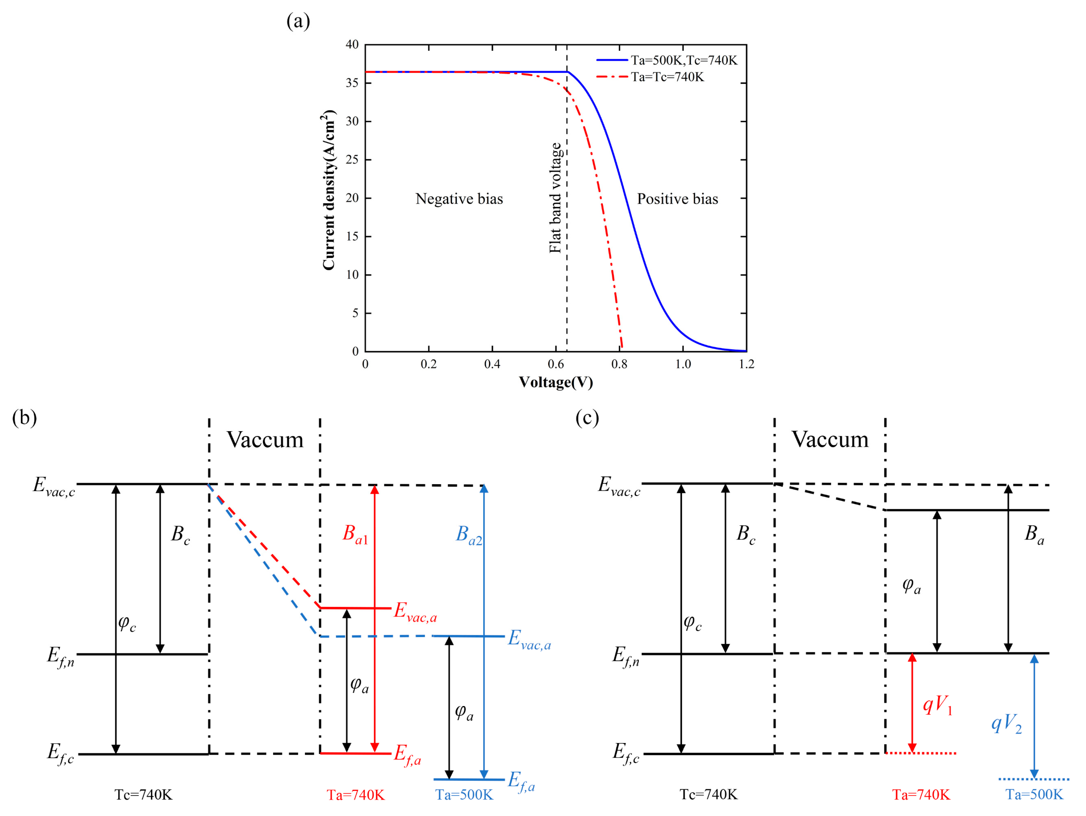
The relationship between the output current and the applied bias under isothermal and nonisothermal operation of the converter is shown in
Figure 6a. The temperature of the cathode was 740 K, which is almost the optimal temperature at 0.6 eV. The figure is divided into two regions: negative bias (
Vbias ≤ 0,
V ≤
Vfb) and positive bias (
Vbias > 0,
V >
Vfb). The external electric field created by applying a negative bias to the converter helped the electrons of the cathode move towards the anode and limited the increase in the reverse current caused by heating of the anode, resulting in the same output current at different anode temperatures. However, the negative bias was close to zero, and the limiting effect of the electric field on the reverse current was weakened; thus, the output current under the isothermal condition began to decline in advance. When the anode temperature was 500 K, the reverse current could be ignored, and the output current remained constant throughout the negative bias region. In the positively biased region, the external electric field severely impeded the emission of electrons from the cathode, causing the output current to drop exponentially. With the increase in positive bias, the output current finally dropped to zero, and the converter reached the open-circuit state. The open-circuit voltage under isothermal conditions was less than that under nonisothermal conditions. The bandgap diagrams are given to illustrate the reasons for the differences in open-circuit voltages.
Figure 6b shows the band diagram with the converter at zero bias. For the sake of illustration, the Fermi level at
Ta =
Tc = 740 K is taken as the reference, and
Ba1 represents the barrier that the anode electron needs to overcome to reach the cathode from the Fermi level at this time. When the anode temperature decreases from 740 K to 500 K, the barrier
Ba1 increases to
Ba2; thus, the positions of the vacuum and Fermi levels of the anode are shown by the blue line. When the cathode is irradiated by sunlight, the Fermi level is raised to the quasi-Fermi level.
Bc represents the barrier that the cathode electrons need to overcome to reach the vacuum level. The band diagram at positive bias is shown in
Figure 6c. When the Fermi level of the anode reaches the same position as the quasi-Fermi level of the cathode, the barrier that the anode electron needs to overcome to reach the cathode is
Ba =
Ba1 −
V1 =
Ba2 −
V2 =
Bc.
V1 and
V2 represent the open-circuit voltage in the isothermal and nonisothermal states, respectively. At this time, no net current is generated inside the converter. Due to
Ba1 <
Ba2,
V1 <
V2 can be obtained; that is, the open-circuit voltage is greater under nonisothermal conditions. This means that there is a larger potential difference between the anode and the cathode in the nonisothermal case than in the isothermal case, so electrons can more easily reach the anode.
Figure 7a shows the relationship between current density and output voltage at different cathode temperatures. When the output voltage is lower than the flat-band voltage (indicated with “+”), the output current increases with temperature and follows the same trend as that shown in
Figure 5b. As the temperature of the cathode increases, the bandgap narrows and the Fermi level rises, resulting in the difference between the work function of the cathode and the anode decreasing, that is, “+” shifting to the left. The inset shows the open-circuit voltage of the converter at different temperatures. The greater the current, the greater the positive bias required for the converter to reach the open-circuit state; therefore, the open-circuit voltage increases as the temperature of the cathode increases. The relationship between the conversion efficiency and the output voltage at different cathode temperatures is shown in
Figure 7b. Under the impact of applied bias pressure, the maximum conversion efficiency is positively correlated with temperature. However, according to
Figure 5c, when the converter operates at zero bias voltage, the maximum conversion efficiency decreases at 800–900 K. This indicates that an appropriate bias voltage can help compensate for the deterioration of conversion efficiency caused by the decrease in the difference between the anode and the cathode work functions.
In order to determine the maximum conversion efficiency point,
Table 1 lists flat-band voltages
Vfb and output voltages
Vm (indicated with “×”) at different temperatures. As the cathode temperature increases, the output voltage
Vm decreases at first and then increases. The reason is that when the applied positive bias begins to increase, the current at temperatures of 600 K and 700 K is small and is greatly affected by the bias, and
Vm is equal to
Vfb and consistent with its trend. However, when the temperature is 800–900 K, the current density is already in the saturation region and slowly increasing. When the positive bias voltage is applied, the current no longer drops instantly but instead undergoes a slow decline process; thus,
Vm obviously exceeds
Vfb. The result shows that with the increase in temperature, the conversion efficiency will eventually reach the maximum at an output voltage greater than the flat-band voltage.
In studies of InGaN single-junction solar cells, the conversion efficiency can be increased from 14.5% to 22.7% by polarization engineering, increasing the back-surface field and window layer and adjusting the doping concentration and thickness optimization [
40,
41,
42]. However, photovoltaic cells have a low utilization of thermal energy from sunlight. In our study, the structure of anode and cathode separation is adopted, and the cathode can simultaneously absorb light and heat in solar energy through PETE effect so as to optimize performance. After cooling the anode, the conversion efficiency can be further improved and linearly increases with electron affinity. Therefore, the PETE converter can make more efficient use of solar energy.


