
Study on Artificial Filter Cake Evaluation Method of Oleophilic Nano-Plugging Agent

Abstract
:1. Introduction
2. Evaluation Method
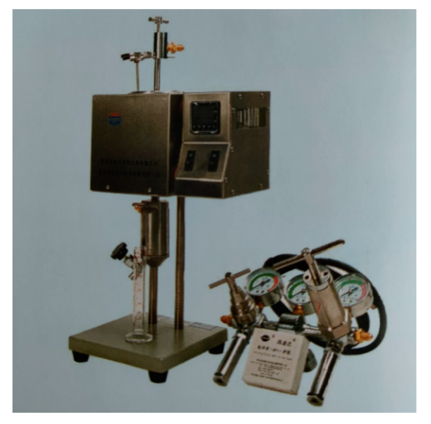
2.1. Experimental Setup
2.2. Optimized Cake Assay Formulation
- Add 0.3% polyacrylamide and 0.9% sodium polyacrylate to 1000 mL of water and stir for 1 h to dissolve completely.
- Add 100 g of nano-barite and 250 g of ordinary barite while stirring, and stir at high speed for 15~20 min to make it fully and evenly mixed.
- Pour into the GGS71 high temperature and pressure dehydration meter scale line (about 200 mL), filter at room temperature, 3.5 × 10⁶ Pa, and prepare the filter cake after two hours of water loss.
- Open the instrument, fill it with clean water, and measure the permeability of the filter cake at a pressure of 3.5 × 10⁶ Pa, which is 10−18–10−19 m2 as qualified.
3. Accuracy and Parallelism Analysis of Evaluation Methods
3.1. Parallelism Analysis
3.2. Accuracy Analysis
4. Field Application
4.1. Application Overview
4.2. Typical Well Example
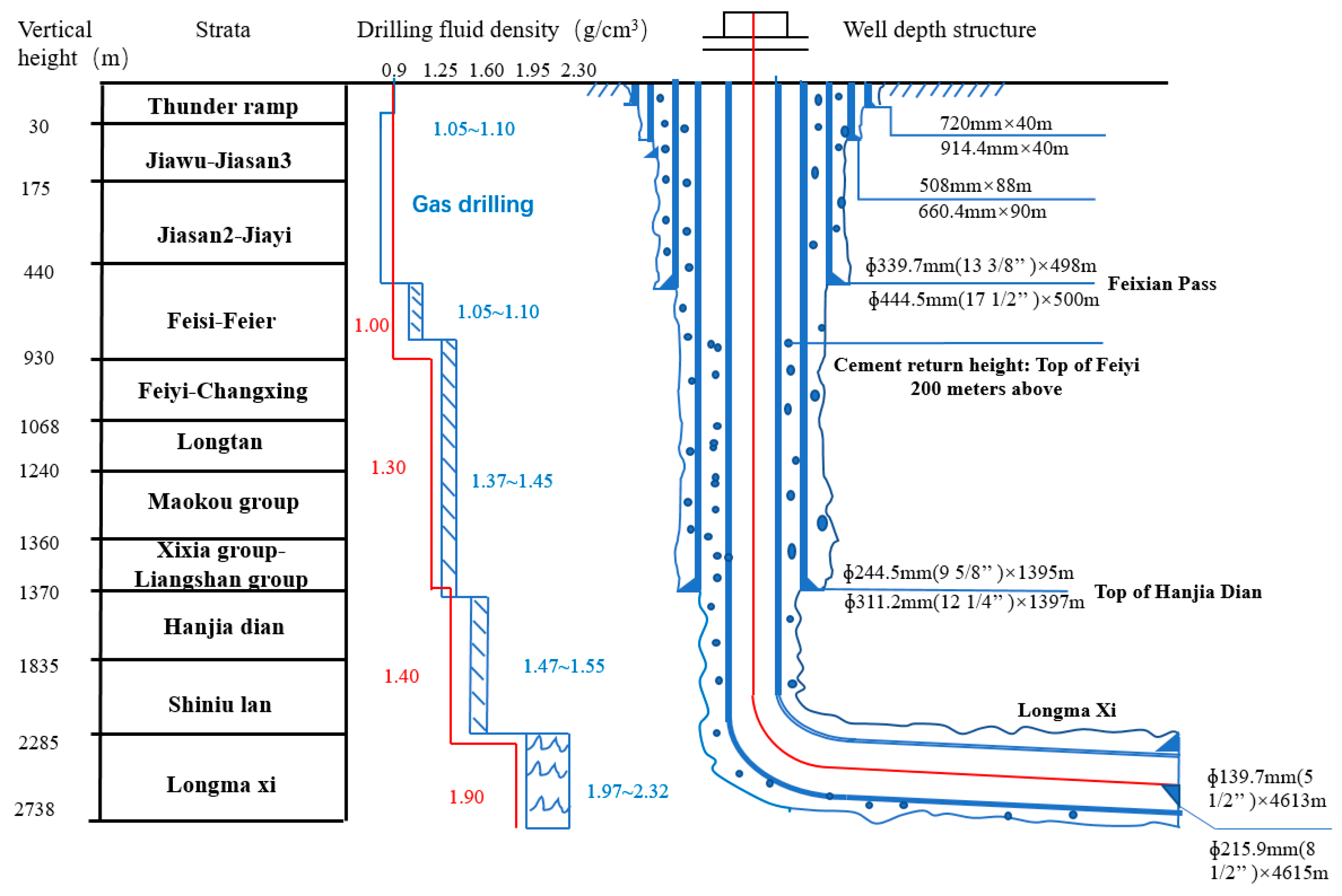
4.2.1. Overview and Drilling Fluid Difficulties
4.2.2. In Situ Application Effects
5. Conclusions
Author Contributions
Funding
Data Availability Statement
Acknowledgments
Conflicts of Interest
References
- Liu, J.; Sun, J. Mechanism and inhibition method of wellbore hydration instability in shale gas reservoir. Drill. Complet. Fluids 2016, 33, 5. [Google Scholar]
- Wang, X.; Bai, D.; Sun, Y.; Li, C.; Lu, Z.; Jing, Y.; Liu, C.; Jiang, L. Enhanced plugging of all oil-based drilling fluid system for shale gas wells—Take Weiyuan Block in Changning Weiyuan National Shale Gas Demonstration Area as an example. Nat. Gas Ind. 2020, 12, 1–5+20. [Google Scholar]
- Chen, X.; Tan, C.P.; Detournay, C. A study on wellbore stability in fractured rock masses with impact of mud infiltration. J. Petrol. Sci. Eng. 2003, 38, 145–154. [Google Scholar] [CrossRef]
- Huang, W.; Qiu, Z.; Xu, J.; Yu, L. Experimental study on wellbore instability mechanism in Western Tuha Oilfield. J. Pet. 2007, 28. [Google Scholar]
- Yue, Q.; Li, Y.; He, B.; Li, Z.; Xiang, X.; Wang, J.; Li, Y. Research on hard and brittle shale in Weizhou 12-1N Oilfield and technical countermeasures for drilling fluid. China Offshore Oil Gas 2005, 17, 44–47. [Google Scholar]
- Chen, L. Research on Evaluation Method and Plugging Mechanism of Drilling Fluid Anti Collapse Plugging; Southwest Petroleum University: Chengdu, China, 2013. [Google Scholar]
- Yang, F.A.; Hou, J. A new method for shale micro fracture simulation and plugging evaluation experiment. Drill. Complet. Fluids 2017, 34, 45–49. [Google Scholar]
- Yan, J. Simulation and simulation plugging experiment of micro fracture core for plugging evaluation. Prospect. Eng. (Geotech. Drill. Eng.) 2018, 45, 18–21. [Google Scholar]
- Wang, J.; Yan, J.; Su, S. A new method for wellbore stability evaluation of hard brittle shale. Pet. Drill. Prod. Technol. 2006, 28–30+83. [Google Scholar] [CrossRef]
- Ma, H.; Zhang, H.; Zhang, Y. Well bore stability analysis based on THM. J. Daqing Pet. Inst. 2008, 32, 50–55. [Google Scholar]
- Huang, R.Z.; Chen, M.; Deng, J.G.; Wang, K.P.; Chen, Z.X. Study on shale stability of wellbore by mechanics coupling with chemistry method. Drill. Fluid Complet. Fluid 1995, 12, 15–22. [Google Scholar]
- Qiu, Z.S.; Xu, J.F.; Lv, K.H.; Yu, L.X.; Wang, Z.M. A multivariate cooperation principle for well-bore stabilization. Acta Pet. Sin. 2007, 28, 117–119. [Google Scholar]
- Li, W.; Wang, P.; Wang, B.; Luo, P.; Yang, K.; Pu, L. After satisfying the asteroid impact on the quality of water-based drilling fluid filter cake. J. Chongqing Inst. Technol. 2014, 4, 69–72. [Google Scholar]
- Hu, Y.; Yue, Q.; Liu, S.; Chen, L. Research on the soft shale drilling fluid in BZ29-4S oilfield. J. OilGas Technol. 2012, 34, 94–97. [Google Scholar]
- Qiu, Z.; Li, J.; Shen, Z. New method for water sensitivity evaluation of shale—A study on specific water wettability. Oil Drill. Prod. Technol. 1999, 21, 1–6. [Google Scholar]
- Qiu, Z.; Ding, R.; Yu, L. The determining method researching of specific surface area for mud shale. Drill. Fluid Complet. Fluid 1999, 16, 9–11. [Google Scholar]
- Cai, J.; Chenevert, M.E.; Sharma, M.M.; Friedheim, J.E. Decreasing Water Invasion into Atoka Shale Using Nonmodified Silica Nanoparticles. SPE Drill. Complet. 2012, 27, 103–112. [Google Scholar] [CrossRef]
- Hoelscher, K.P.; De Stefano, G.; Riley, M.; Young, S. Application of Nanotechnology in Drilling Fluids. In Proceedings of the SPE International Oilfield Nanotechnology Conference and Exhibition, Noordwijk, The Netherlands, 12–14 June 2012. SPE 135642. [Google Scholar]
- Sensoy, T.; Chenevert, M.E.; Sharma, M.M. Minimizing Water Invasion in Shale Using Nanoparticles. In Proceedings of the SPE Annual Technical Conference and Exhibition, New Orleans, LA, USA, 4–7 October 2009. SPE 124429. [Google Scholar]
- Al-Bazali, T.M.; Zhang, J.; Sharma, M.M. Measurement of the Sealing Capacity of Shale Caprocks. In Proceedings of the SPE Annual Technical Conference and Exhibition, Dallas, TX, USA, 9–12 October 2005. SPE 59632. [Google Scholar]
- Cao, X.C.; Qin, Y.; Zhao, Y.N.; Ke, K. Basic Performance Research of Polymer Intercalation Clay. Adv. Mater. Res. 2012, 578, 183–186. [Google Scholar] [CrossRef]
- Srivatsa, J.T.; Ziaja, M.B. An Experimental Investigation on Use of Nanoparticles as Fluid Loss Additives in a Surfactant-Polymer Based Drilling Fluid. In Proceedings of the International Petroleum Technology Conference, Bangkok, Thailand, 7–9 February 2012. [Google Scholar]

| Experiment Serial Number | Cake Making | Clearwater Test | Cake Thickness /10−3 m | Permeability /10−18 m2 Time/h | ||
|---|---|---|---|---|---|---|
| Time/h | Water Loss/mL | Time/s | Water Loss/mL | |||
| 1 | 2 | 30 | 1800 | 11.6 | 3 | 2.07 |
| 2 | 2 | 31 | 1800 | 11.4 | 3 | 2.04 |
| 3 | 2 | 33 | 1800 | 13.5 | 3 | 2.41 |
| 4 | 2 | 32.5 | 1800 | 13.0 | 3 | 2.32 |
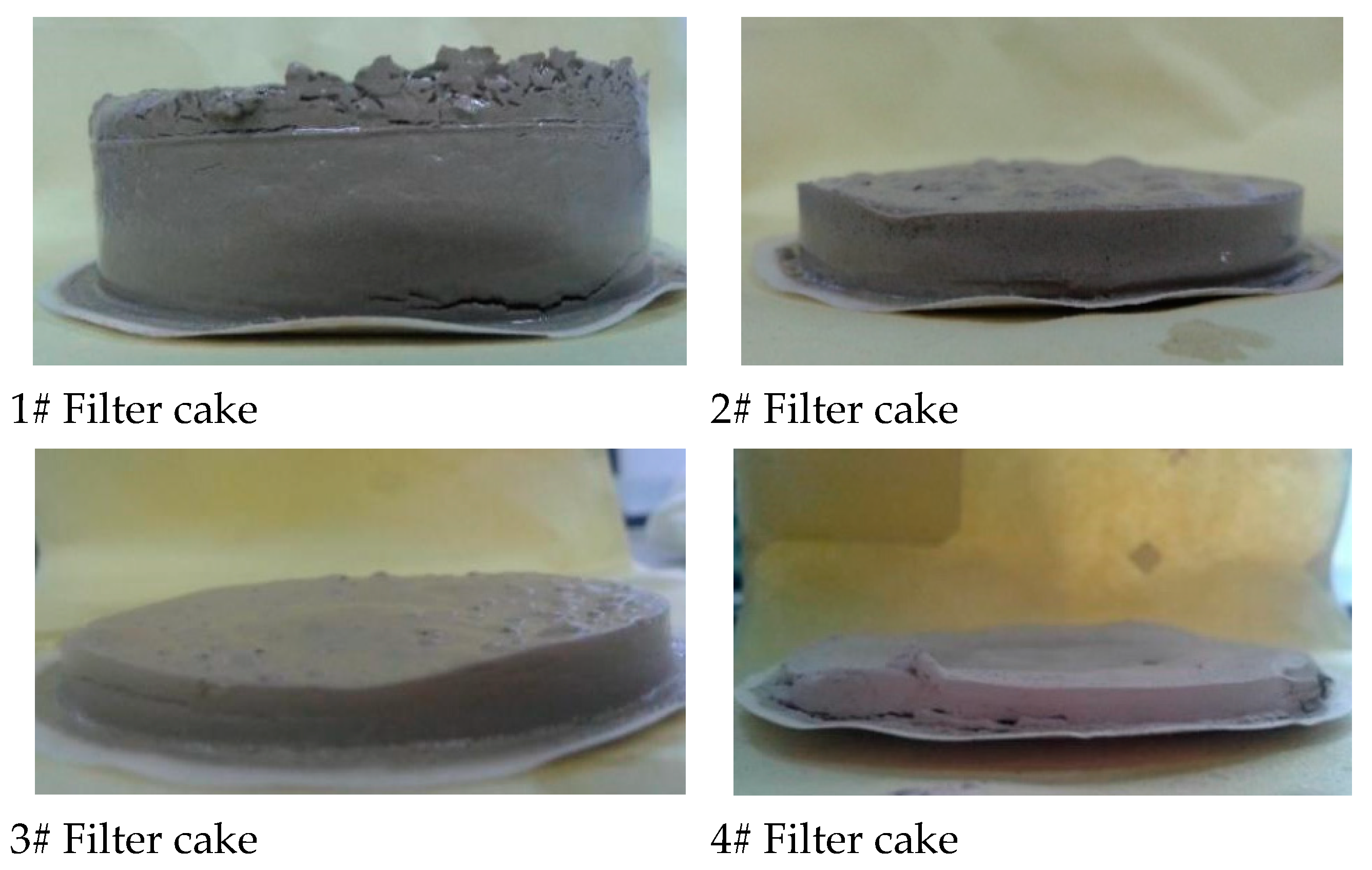
| Experiment Serial Number | Cake Making | Clearwater Test | Cake Thickness /10−3 m | Permeability /10−18 m2 | ||
|---|---|---|---|---|---|---|
| Time/h | Water Loss/mL | Time/s | Water Loss/mL | |||
| 1# | 2 | 90 | 1800 | 28.5 | 17.20 | 30.723 |
| 2# | 2 | 22 | 1800 | 2.9 | 8.82 | 1.605 |
| 3# | 2 | 25 | 1800 | 3.2 | 5.40 | 1.085 |
| 4# | 2 | 19 | 1800 | 2.4 | 3.24 | 0.429 |
| Polyacrylamide/% | Sodium Polyacrylate/% | Cake Making | Clearwater Test | Cake Thickness /10−3 m | Permeability /10−18 m2 | ||
|---|---|---|---|---|---|---|---|
| Time/h | Water Loss/mL | Time/s | Water Loss/mL | ||||
| 0.3 | 0.3 | 2 | 60 | 1800 | 14.0 | 9 | 0.0498 |
| 0.3 | 0.8 | 2 | 19 | 1800 | 2.0 | 3 | 1.0465 |
| 0.3 | 0.9 | 2 | 20 | 1800 | 2.2 | 3 | 0.9514 |
| 0.3 | 1.0 | 2 | 25 | 1800 | 4.0 | 2 | 0.7849 |
| Experiment Serial Number | Cake Making | Clearwater Test | Cake Thickness /10−3 m | Permeability /10−18 m2 | ||
|---|---|---|---|---|---|---|
| Time/h | Water Loss/mL | Time/s | Water Loss/mL | |||
| 1 | 2 | 17.5 | 1800 | 2.5 | 3.12 | 0.447 |
| 2 | 2 | 18 | 1800 | 2.4 | 3.20 | 0.429 |
| 3 | 2 | 15 | 1800 | 2.2 | 2.96 | 0.393 |
| 4 | 2 | 18 | 1800 | 2.5 | 2.98 | 0.447 |
| 5 | 2 | 17.5 | 1800 | 2.4 | 2.95 | 0.429 |
| 6 | 2 | 18.5 | 1800 | 2.2 | 3.05 | 0.393 |
| 7 | 2 | 21 | 1800 | 2.4 | 3.01 | 0.429 |
| 8 | 2 | 17 | 1800 | 2.2 | 2.97 | 0.393 |
| 9 | 2 | 24.5 | 1800 | 2.4 | 3.05 | 0.429 |
| 10 | 2 | 25.5 | 1800 | 2.0 | 2.89 | 0.358 |
Disclaimer/Publisher’s Note: The statements, opinions and data contained in all publications are solely those of the individual author(s) and contributor(s) and not of MDPI and/or the editor(s). MDPI and/or the editor(s) disclaim responsibility for any injury to people or property resulting from any ideas, methods, instructions or products referred to in the content. |
© 2023 by the authors. Licensee MDPI, Basel, Switzerland. This article is an open access article distributed under the terms and conditions of the Creative Commons Attribution (CC BY) license (https://creativecommons.org/licenses/by/4.0/).
Share and Cite
Dai, F.; Luo, P.; Wu, C.; Wang, R.; Liu, Y.; Huang, W. Study on Artificial Filter Cake Evaluation Method of Oleophilic Nano-Plugging Agent. Energies 2023, 16, 3559. https://doi.org/10.3390/en16083559
Dai F, Luo P, Wu C, Wang R, Liu Y, Huang W. Study on Artificial Filter Cake Evaluation Method of Oleophilic Nano-Plugging Agent. Energies. 2023; 16(8):3559. https://doi.org/10.3390/en16083559
Chicago/Turabian StyleDai, Feng, Pingya Luo, Chunlin Wu, Rui Wang, Yingmin Liu, and Weian Huang. 2023. "Study on Artificial Filter Cake Evaluation Method of Oleophilic Nano-Plugging Agent" Energies 16, no. 8: 3559. https://doi.org/10.3390/en16083559