Abstract
Both scientific and industrial communities have a growing interest in marine renewable energies. There is a wide variety of technologies in this domain, with different degrees of maturity. This study focuses on two models of a mast-free vertical axis Darrieus tidal turbine with the objective of characterizing the effect of vertical confinement, rotor configuration, and fluid–structure interactions on their performances in free-surface flows. The first model comprised four straight rigid blades maintained by circular flanges on both ends of the rotor and the second model is equipped with free-ended interchangeable blades attached to a single upper flange. Two configurations of the second model mounted with either rigid or flexible blades were used, first for comparison with the dual-flange turbine, then in order to address the effect of fluid–structure interactions on the turbine performances. While the single-flange models exhibit a significantly lower efficiency at all operating points, it is observed that the use of flexible blades tends to enhance turbine performances at low Reynolds numbers. The flow topology obtained from PIV measurement at selected operating points is discussed with respect to the performance of each turbine model in order to highlight the role of the dynamic stall and blade–vortex interactions.
1. Introduction
Marine renewable energies are attracting growing interest in the scientific, industrial, and political communities. A wide variety of technologies are involved in this sector, with varying degrees of maturity. This study focuses on tidal turbines whose technology is close to the industrial stage. Two cross-flow Darrieus turbines with four straight blades held by circular flanges on either one or both sides of the rotor were investigated. The first example of such a turbine can be found in George Darrieus’s patents filed in France [1] and in the United States [2]. Various designs of Darrieus turbines have been investigated since, and a review is given in [3]. Despite the well-known risk of failure of rapidly rotating cross-flow turbines, little research has been devoted to the fluid–structure interactions (FSI) affecting this family of wind or water turbines. Consequently, the DYNEOL project, funded by the French National Agency of Research (ANR), aims at investigating the structural response of Darrieus turbine blades under cyclic fluid loads. With the aim of characterizing the generic behavior of a Darrieus turbine at both blade and rotor levels, the mast-free rotor concept used in [4] is replicated in this study, and then modified by removing the lower flange in order to study the influence of free-ended blades with or without flexibility effects. The two rotor designs can respectively be compared with mast-free giromills and halved H-type turbines as described in [5].
Dynamic stall is one of the particular phenomena occurring during Darrieus turbine operation. To date, only a few studies have been devoted to its characterization. Laneville and Vittecoq [6] presented measurements of drag-lift hysteresis cycles exerted on the blades of a two-bladed Darrieus turbine and linked them to a limited range of the advance parameter, or tip speed ratio (TSR), defined as the ratio between the tangential velocity of the rotating blades and the incoming flow velocity. Brochier et al. [7] performed flow visualizations by dye injection around the blades of a two-bladed Darrieus turbine equipped with a symmetrical NACA0018 [8] airfoil. They confirmed that the blade–vortex interactions occurring at adequate advance parameters can increase the turbine performances. Fujisawa and Shibuya [9] carried out PIV measurements on a single-bladed Darrieus turbine with a NACA0018 profile for low Reynolds numbers and low turbulence regimes, then Ferreira et al. [10] studied the evolution of dynamic stall vortices by PIV measurements in a wind tunnel on a single rotating NACA0015 blade for values of the advance parameter varying from 2 to 4 at a Reynolds number of 7 × 10⁴. Their respective measurement results helped quantify the dynamics of the stall and the evolution of the shed vortex (Buchner et al. [11]).
Fluid–structure interactions and their effect on the behavior of Darrieus turbines have received little attention in the existing literature. Various authors have proposed to take advantage of passive pitching blades to enhance turbine performance (Zeiner-Gundersen [12], Lazauskas and Kirke [13], and Kirke and Paillard [14]). Similarly, MacPhee and Beyene [15], Butbul et al. [16], and Hoerner et al. [17] have respectively simulated and experimented with specifically designed chord-wise bending blades subject to fluid–structure interactions. The 3D passive deformation of the blades has been analytically and numerically addressed by Hameed and Afaq [18], mainly evidencing the role of centrifugal effects on both the span- and chord-wise bending. The coupled CFD-CSM simulations of Liu and Xiao [19] have then shown that the combined effect of stiffness and structural boundary conditions could lead to either enhancement or degradation of turbine performance. It is worth mentioning that flutter analysis and experiments have been conducted by Ham [20] and Popelka [21], in which flutter was manually triggered and monitored through torque measurements. However, to the best of our knowledge, no experimental work yet reports the influence of blade flexibility on the performance and behavior of Darrieus turbines.
The present work focuses on experimental studies on Darrieus turbines in varying operating conditions. First, the different operating modes of a reference, fully rigid, turbine model have been identified using torque measurements for various flow regimes. For a fixed value of the Reynolds number, the effect of modifying the water level is investigated first, as this parameter affects both the Froude number of the flow and the blockage ratio between the turbine apparent section and the test section. Then, the performance of the turbine over a range of advance parameters is studied. The modular turbine model allowing the use of free-ended blades of different materials is investigated next over a selected range of operating points and for two different blade rigidities. The second part of the study presents the results of the PIV measurement obtained around the optimal operating points of the three turbine configurations. The occurrence of dynamic stall is verified for all the studied advance parameters, and significant blade–vortex interactions are observed near the optimal operating points. Switching from the reference turbine model to the free-ended rigid blade turbine model first results in a loss of efficiency that can be associated with the three-dimensionalization of the flow in the vicinity of the blade tips. The kinematics of vortex shedding are also influenced by the change in the model, with evidence of a vortex line curvature. The flow and performance characteristics of the free-ended blade model are also modulated as soon as the rigid blades are replaced by flexible ones. Significant changes in the dynamic stall kinematics and blade–vortex interaction sequences are also observed with the change in configurations.
2. Materials and Methods
The experiments are carried out in the free surface channel of the Environmental Hydrodynamics Platform of the PPRIME Institute, a photograph of which is shown in Figure 1. The test section of the flume is 15 m long by B = 1 m wide and Hmax = 1 m high. The flow discharge is denoted Q and its maximum value is Qmax = 0.5 m3/s. The water level is denoted H and the discharge velocity V0 = Q/BH.

Figure 1.
Overview of the water flume.
The turbine model, as illustrated in Figure 2a, has a diameter of D = 400 mm and a wingspan of W = 400 mm. The 4 straight blades are based on a NACA0015 section of c = 80 mm chord. Each of the blades is attached at its ¼ chord and tangent to the rotor perimeter. The rotor is driven in rotation by a servomotor and is equipped with torque and angular position sensors. The blockage ratio associated with the turbine front area is defined as b = DW/BH. For the range of water levels used in this study, its value varies from 21% to 29%.
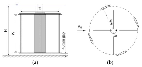
Figure 2.
Rotor geometry with optional lower flange and dimensions (a) and angular reference (b).
The blade positioning and angular references are defined in Figure 2b, in which θ describes the azimuthal position of an individual blade with respect to the transverse axis and ω describes the angular velocity of the turbine.
The reference turbine model holds rigid blades held between two horizontal end flanges as shown in Figure 2a and Figure 3a. The modified Darrieus turbine comprised a single top flange in which the free-ended blades are inserted and clamped using end caps (Figure 3b). Two blade materials are used: stainless steel (Young modulus E = 190 GPa) for comparison with the rigidly assembled turbine and 30% carbon-fiber-reinforced PEEK (Polyetheretherketone, E = 6 Gpa) to investigate the effect of blade flexibility. In identical flow conditions, steel blade deformations are then expected to be of the order of 3% of the PEEK blade deformations.
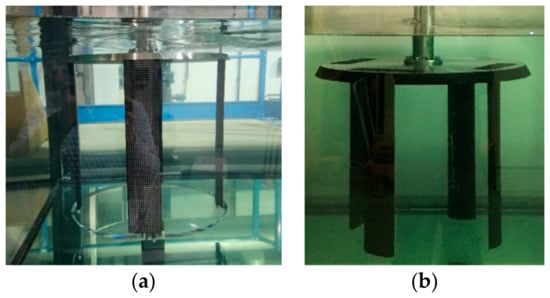
Figure 3.
Photographs of the reference (a) and free-ended blades. (b) Darrieus turbines as installed in the experimental facility.
The flow regime can be described by three main non-dimensional parameters. First, the chord-based Reynolds number is defined as follows:
The Froude number based on the water level indicates whether the upstream flow is inertia or gravity-dominated. At the turbine level, this parameter also influences the blockage ratio b.
In this study, Froude numbers never exceed 0.39, ensuring a fluvial regime in all flow configurations. The operating points of the turbine are characterized by the advance parameter, or tip-speed ratio (TSR), defined as the non-dimensional velocity ratio between the blade motion and the upstream flow:
An additional parameter based on the Cauchy number is used to characterize the relative bending of the free-ended blades subject to fluid loads:
where I is the moment of inertia of the blade cross-sectional area with respect to the chord axis. Here, the nominal Cauchy number /E [22] characterizing the deformation of an elastic solid of Young modulus E under fluid loads is modified to integrate both the flexural rigidity EI of the blade and the maximum lift forces exerted during the rotation cycle. This parameter represents the inverse of a non-dimensional stiffness as used for example in Shyy et al. [23]. Seen from the Euler–Bernoulli beam theory, the Cauchy number is a measure of the beam deflection relative to its length. For the PEEK blades, the modified Cauchy number varies from 0.09 to 2.7 depending on the flow regime and advance parameter. Assuming uniformly distributed loading, the equivalent maximum static deflection of the blades is therefore of the order of 10 mm. Comparatively, the maximum deflection of the stainless steel blades would be less than 0.5 mm for a maximum Cauchy number of 0.08.
Torque measurements were carried out to characterize the performances of the turbines at different operating regimes. Planar PIV (particle image velocimetry) measurements were then conducted around the optimal regime of each turbine. The flow measurements were phase locked with the turbine rotation speed in order to obtain measurements every 7.5°. The PIV setup comprised a dual exposure CCD camera (Lavision Imager LX 16M, 4920 × 3280 pixels, 8.8 fps max.) and two Nd:YAG 532 nm double-pulsed lasers (Quantel Twins CFR 2 × 120 mJ and 2 × 190 mJ). The laser heads are positioned in a side-by-side horizontal arrangement and symmetrically oriented at ±20° from the ormal to the flume side wall in order to maximize the illuminated area and reduce the shading due to the moving blades. The camera is positioned below the flume and images the region of interest through a 45° mirror. The resulting measurement area is 1140 mm long in the flow direction and 760 mm wide, starting 540 mm upstream of the rotor axis. An overview of the PIV system is provided in Figure 4.
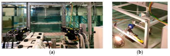
Figure 4.
PIV system using double laser illumination (a) and dual frame PIV camera placed below the flume (b).
Seeding is provided by micro-bubbles generated from a valve installed in a low-pressure area of the flume piping system. This solution prevents the use of artificial seeding particles in the facility. Examples of normalized raw images acquired by the system are presented in Figure 5 for both the double and single flange rotors. Complete shading due to the moving blades is limited to the immediate vicinity of the blades while most of the region of interest benefits from either single or double laser illumination. White streaks locally appear in the PIV images due to laser reflections on the free surface perturbed by the wake. For the double flange rotor, the tapered perimeter of the transparent lower flange also generates laser reflections that are visible on the raw images. For both rotors, less intense reflections can also be observed on the perimeter of the top flange.
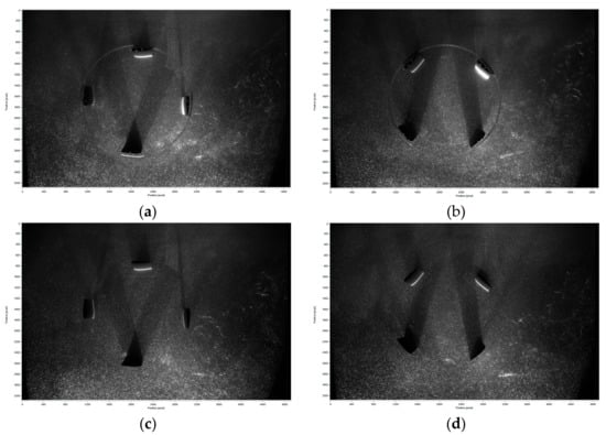
Figure 5.
Examples of normalized raw PIV images obtained for the double flange (a,b) and single flange (c,d) rotors at θ = 0° (a,c) and θ = 45° (b,d). Flow is from left to right.
The Lavision Davis 10 software is used to process the dual frame PIV images using a 4-pass algorithm with adaptive window shifting and second-order deformations [24]. The initial and final interrogation cell sizes are respectively 642 and 322 pixels with 50% final overlap. The resulting velocity fields have a resolution of one vector every 3.7 mm. For each measurement series, the PIV interframe time is adjusted to limit the maximum apparent displacement to 1/4th of the final interrogation cell [25]. Based on a maximum expected velocity λV0, the resulting uncertainty on the estimated velocities is of the order of 1% of this value.
3. Results
3.1. Turbine Performances
Torque measurements were conducted for all turbine models over a range of operating conditions characterized by parameters Re = 5.2 × 10⁴ to 7.3 × 10⁴, Fr = 0.24 to 0.39, and λ = 0.5 to 3. These parameters correspond to upstream flow velocities ranging from 0.66 m/s to 0.91 m/s and water depths from 0.55 m to 0.75 m. For lower depths, the flow immediately downstream of the turbine gets significantly aerated and is not considered in this study. The highest reachable Reynolds number is therefore limited by both the maximum flow rate and this lower water level limit. The performance of the turbine is rated using its coefficient of power (COP) defined as follows:
in which C represents the cycle-averaged measured torque. In the present study, both the lateral and vertical confinements of the flow induce an overestimation of the maximum available COP, which can be addressed using the correction proposed by Garrett and Cummins [26].
Figure 6 shows the evolution of the reference turbine COP at the lowest Reynolds number, reachable for all water levels given the maximum discharge of the experimental flume. The Froude number and blockage ratio respectively range from Fr = 0.24 to Fr = 0.28 and b = 21% to 29% in these series of experiments.
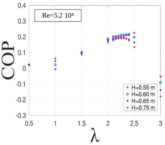
Figure 6.
COP sensitivity of the reference turbine to the water level at Re = 5.2 × 10⁴ (Fr = 0.24 to 0.28).
The flow confinement occurring for the lowest water depths results in a slight increase in the COP, from COP = 0.2 to 0.22, with a significant displacement of the optimal operating point towards higher advance parameters. A remarkable feature of these COP characteristics concerns the influence of the water level for varying advance parameters. For a TSR significantly below the optimal (λ = 1 to 2.2 here), a higher water level leads to a higher COP. This trend is then reversed as the TSR reaches, or passes (for H = 0.65), the optimal operating point. In other words, the water turbine is more efficient at low TSR in deep water and at high TSR in shallow water. It can also be observed that the COP slope is steeper at a low water level and low TSR, making the operational range of the turbine more selective in shallow water than in deep water.
In Figure 7 and Figure 8, the COP of the three turbine models (rigid assembly, free-ended stainless steel, or PEEK blades) are plotted for the lowest water level at both the lowest and highest Reynolds numbers, respectively. The combined effects of the Reynolds and Froude numbers on the efficiency of the rigidly assembled turbine clearly appear as the maximum COP increases from 0.32 to 0.39 with an optimal advance parameter decreasing from λ = 2.4 to λ = 2.25. This evolution of the turbine performances is in agreement with the findings of Howell et al. [27] for wind turbines at slightly lower Reynolds numbers. The COP significantly increases with the Reynolds number while the optimal operating range of the turbine is both decreased and narrowed in terms of the advance parameter. In comparison, the turbine models with free-ended blades exhibit significantly lower performance due to the three-dimensionalization of the flow at the tip of the blade and within the small clearance separating the blades from the flume bed. It can be observed that the COP values significantly increase by up to 30% with the Reynolds number in the case of free-ended rigid blades, whereas the benefit is limited to less than 5% when the more flexible blades are used.
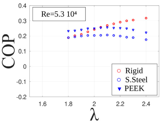
Figure 7.
COP comparison between the three turbine models at Re = 5.3 × 10⁴ and Fr = 0.28.
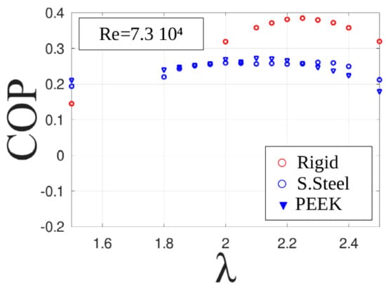
Figure 8.
COP comparison between the three turbine models at Re = 7.3 × 10⁵ and Fr = 0.39.
At the higher Reynolds number, the COP curves of the two free-ended turbine models become similar; however, a still slightly higher COP of up to λ = 2.2 is obtained when flexible blades are used. Conversely, for the highest advance parameters, rigid blades offer better performance as the COP values are less subject to decreasing.
These series of results clearly indicate that passive blade flexibility can enhance the performance of the turbine for well-chosen operational conditions. Focusing on the optimal advance parameter λ = 2.1 for the free-ended blades rotor at these 2 Reynolds numbers, the Cauchy number associated with the PEEK blades increases from Ca = 0.86 to Ca = 1.63, and from Ca = 0.027 to 0.052 for the steel blades. The blade deflection is therefore in a 2:1 ratio between the two flow regimes, with a 32:1 ratio between the steel and PEEK blades. These observations support the hypothesis that the adjustment of blade flexibility with respect to the foreseen operating regime of a turbine may either act in favor of better efficiency or could possibly decrease it, as predicted by Liu and Xiao [19].
3.2. Flow Topology
The flow is investigated at mid-height of the rotors around the optimal operating points of each turbine model using PIV (λ = 2.10; 2.25; and 2.40 for the rigid assembly and λ = 1.90; 2.10; 2.25; and 2.30 for the freed-ended models), for a unique water level H = 0.55 m. The phase-locked measurements are conducted every 7.5° from the azimuthal position θ = 0° to θ = 90°, allowing phase averages over individual series of 1000 PIV fields. Taking into account the 90° periodicity of the 4-bladed rotors, the entire operation cycle is therefore covered.
An overview of the flow topology is represented in Figure 9 for the optimal operating point of the reference, rigidly assembled, turbine model. The whitened areas surrounding the blades correspond to shaded zones that could not be illuminated using the two lasers. For this rotor, laser reflections on the lower transparent flange locally result in spurious velocity estimates. The corresponding thin circular arcs are visible inside the rotor and have however been kept to ensure a global view of the flow.
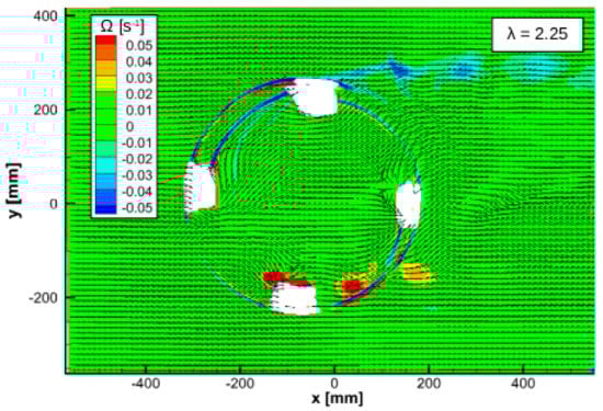
Figure 9.
Averaged out-of-plane vorticity distribution at θ = 0°–90°–180°–270°. Rigid assembly; Re = 7.3 × 10⁵; and Fr = 0.39; λ = 2.25.
The averaged out-of-plane vorticity distribution at 0° azimuth reveals the periodic clockwise vortex shedding (blue spots) occurring around θ = 0° as well as the development of the boundary layers on both sides of the wing in the first (θ = 0° to θ = 90°) and third (θ = 180° to θ = 270°) quadrants, and, to a lesser extent, in the second and fourth quadrants. The most noticeable feature of the flow is the counter-clockwise vortex shedding due to dynamic stall (red spots), occurring around θ = 135° and possibly leading to blade–vortex interactions in the third quadrant. For this 4-bladed rotor and advance parameters of the order of 2, 2 vortices generally co-exist within the rotor due to this particular combination of velocity ratio and the number of blades.
The kinematics of the dynamic stall vortex released from the leading edge in the second quadrant are schematically represented in Figure 10 for advance parameters of the order of 2. Its undisturbed trajectory is in agreement with the observations of Brochier et al. [7], Fujisawa and Shibuya [9], and Fereira et al. [10] for single-blade turbines. In this series of experiments, however, the trailing edge vortex reported at low Reynolds numbers by Brochier et al. [7] and Fujisawa and Shibuya [9] is not observed as in Fereira et al. [10] at comparable Reynolds numbers. The once stalled blade pursues its rotation, leaving behind the released vortex that is advected along a trajectory of decreasing curvature. In the case of the 4-blade turbine models used in this study, blade–vortex interactions occur as the vortex is caught up by the next blade while crossing the perimeter of the rotor in the third quadrant.
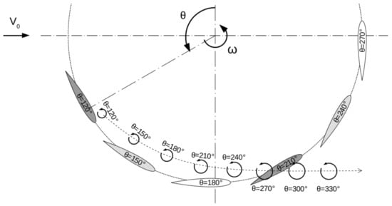
Figure 10.
Typical kinematics of the leading edge vortex released during the dynamic stall. For the advance parameters around λ = 2, the blade–vortex interactions can occur between azimuth θ = 180° and θ = 240°.
A sample view of the blade–vortex interaction is presented in Figure 11 at azimuth 225° for the 3 advance parameters surrounding the optimal operation point. The differences in flow topology between these operating conditions are tenuous, with apparently identical vortex kinematics, yet the COP is lowered by nearly 7% for λ = 2.25 ± 0.15. In this respect, the results of Gorle et al. [4] indicate that positive torque is mainly obtained in the two first quadrants until the blade has traveled far downstream of the vortex shed during the dynamic stall. The blade then briefly benefits from fluid forces induced by its own vortex and the vortex shed from the preceding blade. Thus, within this part of the cycle, the fluid forces exerted on the blade have a propulsive effect on the rotor. However, destructive blade–vortex interactions are likely to occur as soon as the blade directly impinges on the downstream vortex. Additionally, the induced fluid forces get reversed as the vortex crosses the blade trajectory and leaves the inner part of the rotor.
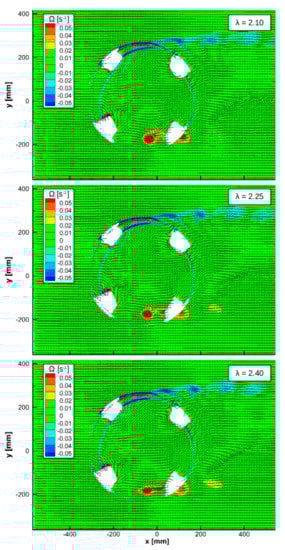
Figure 11.
Averaged out-of-plane vorticity distribution at θ = 225°. Rigid assembly; Re = 7.3 × 10⁵; Fr = 0.39; and λ = 2.10; 2.25; 2.40.
On Figure 11, the 2 counter-clockwise vortices surrounding the θ = 225° blade illustrate this competition between induced forces and impingement. For λ = 2.10, the blade–vortex interaction is almost nonexistent. For λ = 2.25, the interaction starts to establish, and it strengthens at λ = 2.40. Up to the optimal advance parameter, the blade tends to approach closer to the downstream vortex, gradually maximizing the propulsive torque. At higher λ, the de-structuring effect of the interaction limits the beneficial effect of the induced load.
The flow topology is significantly changed when free-ended blades are used. In the mid-plane of the rotor, a dynamic stall occurs at larger azimuthal positions, which may maintain the propulsive torque longer in the first quadrants but also modifies the forces induced by the shed vortices. This is evidenced around azimuth 180° in Figure 12 and Figure 13.
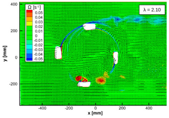
Figure 12.
Averaged out-of-plane vorticity distribution at θ = 0°. Stainless steel blades; Re = 7.3 × 10⁵; Fr = 0.39; and λ = 2.10.
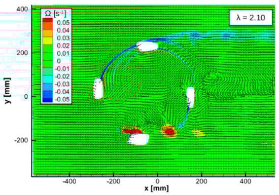
Figure 13.
Averaged out-of-plane vorticity distribution at θ = 0°. PEEK blades; Re = 7.3 × 10⁵; Fr = 0.39; and λ = 2.10.
The significantly lower performances of the free-ended blades can first be attributed to the 3D features generated at the blade tips, among which the tip vortices have a detrimental down-washing effect. As a consequence, the modified vortex kinematics observed here are of lesser influence on the COP. It is however observable in Figure 12, Figure 13, Figure 14 and Figure 15 that when using the more flexible PEEK blades, the downstream vortices remain closer to the blades once they have crossed the rotor perimeter. Although this observation would need further quantification, this may act in favor of the slightly higher COP obtained with flexible blades.
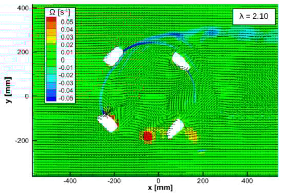
Figure 14.
Averaged out-of-plane vorticity distribution at θ = 225°. Stainless steel blades; Re = 7.3 × 10⁵; Fr = 0.39; and λ = 2.10.
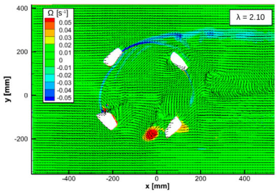
Figure 15.
Averaged out-of-plane vorticity distribution at θ = 225°. PEEK blades; Re = 7.3 × 10⁵; Fr = 0.39; and λ = 2.10.
4. Discussion
Within the framework of the DYNEOL ANR project aiming at modeling and understanding the structural response of Darrieus turbine blades, experiments have been conducted on three different configurations of a Darrieus turbine model with a focus on the influence of the vertical confinement, turbine type, and, finally, fluid–structure interactions on their performances. The rigidly assembled model provided reference results against which the modified model with either rigid or flexible free-ended blades was compared.
The results in terms of turbine performance as a function of their design and operating conditions are in agreement with the existing literature. The flow kinematics were investigated using PIV around the optimal operating points of each model, confirming that both turbine models were operating accordingly to what had been observed in past studies. The role of the vortex advection subsequent to dynamic stall was discussed. It is suggested that, for increasing advance parameters, the presence of these counter-rotating vortices in the inner part of the rotor is beneficial to blade propulsion as long as no detrimental blade–vortex interaction occurs. In the case of free-ended blades, and though dynamic stall is delayed, this interaction takes place earlier in the cycle than for the dual flange turbine, which notably results in smaller optimal advance parameters, and, in addition to significant 3D effects, lower efficiency. With the reference model being analog to a mast-free giromill and the modified model being analog to a halved H-type turbine, these findings allow a quantitative and qualitative comparison of these two classic configurations.
In the framework of fluid–structure interactions studies, the modified rotor with free-ended blades proved to be adequately dimensioned for generating blade deformations that can alter its behavior. The first results on the use of flexible elastic blades instead of rigid ones evidence their beneficial effect on the turbine performances for all tested regimes. It can be emphasized that moderate flexibility effects act in favor of better turbine efficiency up to a limiting value of the Cauchy number, above which flexible blades do not seem to bring noticeable improvement compared with rigid ones. It is a reasonable assumption to consider that too large flexibility should result in a loss of efficiency, as the blades would eventually bend excessively and not efficiently transmit the cyclic fluid loads. Complementary quantified investigations and analyses on a wider selection of materials are therefore needed to further assess the actual influence of blade compliance on both the flow dynamics and turbine performance.
Author Contributions
Conceptualization, L.C.; methodology, M.-L.K.-M., L.C. and L.T.; investigation, M.-L.K.-M., L.C. and L.T.; writing—original draft preparation, M.-L.K.-M., L.C. and L.T.; writing—review and editing, M.-L.K.-M., L.C. and L.T.; visualization, M.-L.K.-M., L.C. and L.T.; supervision, L.C. and L.T.; project administration, L.C.; funding acquisition, L.C. All authors have read and agreed to the published version of the manuscript.
Funding
This research and M.-L.K.-M.’s Ph.D. were funded by the French National Agency for Research (ANR), project DYNEOL (ANR-17-CE06-0020).
Data Availability Statement
The data presented in this study are available on request from the corresponding author.
Conflicts of Interest
The authors declare no conflict of interest.
Abbreviations
| Symbols | |
| A | Front area of the rotor [m2] |
| B | Channel width [m] |
| c | Blade chord [m] |
| C | Torque measured on the rotor shaft [Nm] |
| Ca | Cauchy number |
| D | Rotor diameter [m] |
| E | Young modulus |
| Fr | Froude number |
| H | Water height |
| I | Blade second-order moment of area |
| λ | Advance parameter |
| m, ma | Blade mass and added mass |
| ν | Fluid kinematic viscosity [m2/s] |
| ω | Rotor angular velocity [rad/s] |
| ρ | Fluid density [kg/m3] |
| Re | Chord-based Reynolds number |
| θ | Blade and rotor azimuthal position [°] |
| V0 | Mean upstream flow velocity [m/s] |
| W | Blade wingspan |
| Abbreviations | |
| ANR | Agence Nationale de la Recherche |
| CFD | Computational fluid dynamics |
| COP | Coefficient of power |
| CSM | Computational solid mechanics |
| FSI | Fluid–structure interactions |
| NACA | National Advisory Committee for Aeronautics |
| PEEK | Polyetheretherketone |
| PIV | Particle image velocimetry |
| TSR | Tip speed ratio |
References
- Darrieus, G. Brevet Français n°604.390. 1925. Available online: https://data.inpi.fr/brevets/FR604390 (accessed on 6 April 2023).
- Darrieus, G. Turbine Having its Rotating Shaft Transverse to the Flow of the Current. US Patent 1835018, 8 December 1931. [Google Scholar]
- Bhutta, M.M.A.; Hayat, N.; Farooq, A.U.; Ali, Z.; Jamil, R.; Hussain, Z. Vertical axis wind turbine—A review of various configurations and design techniques. Renew. Sustain. Energy Rev. 2012, 16, 1926–1939. [Google Scholar] [CrossRef]
- Gorle, J.M.R.; Chatellier, L.; Pons, F.; Ba, M. Flow and performance analysis of H-Darrieus hydroturbine in a confined flow: A computational and experimental study. J. Fluids Struct. 2016, 66, 382–402. [Google Scholar] [CrossRef]
- Sutherland, H.J.; Berg, D.E.; Ashwill, T.D. A Retrospective of VAWT Technology; Technical Report SAND2012-0304; Sandia National Lab.: Albuquerque, NM, USA, 2012. [Google Scholar]
- Laneville, A.; Vitecoq, P. Dynamic stall: The case of the vertical axis wind turbine. J. Sol. Energy Eng. 1986, 108, 140–145. [Google Scholar] [CrossRef]
- Brochier, G.; Fraunié, P.; Béguiert, C.; Paraschivoiu, I. Water Channel Experiments of Dynamic Stall on Darrieus Wind Turbine Blades. J. Propuls. 1986, 2, 445–449. [Google Scholar] [CrossRef]
- Jacods, E.N.; Ward, K.E.; Pinkerton, R.M. The Characteristics of 78 Related Airfoil Sections from Tests in the Variable-Density Wind Tunnel; NACA Technical Report 460; National Advisory Committee For Aeronautics: Washington, DC, USA, 1933. [Google Scholar]
- Fujisawa, N.; Shibuya, S. Observations of dynamic stall on Darrieus wind turbine blades. J. Wind Eng. Ind. Aerodyn. 2001, 89, 201–214. [Google Scholar] [CrossRef]
- Ferreira, C.J.S.; Kuik, G.V.; van Bussel, G.V.; Scarano, F. Visualization by PIV of dynamic stall on a vertical axis wind turbine. Exp. Fluids 2009, 46, 87–108. [Google Scholar]
- Buchner, A.-J.; Soria, J.; Honnery, D.; Smits, A.J. Dynamic stall in vertical axis wind turbines:scaling and topological considerations. J. Fluid Mech. 2018, 841, 746–766. [Google Scholar] [CrossRef]
- Zeiner-Gundersen, D.H. A novel flexible foil vertical axis turbine for river, ocean, and tidal applications. Appl. Energy 2015, 151, 60–66. [Google Scholar] [CrossRef]
- Lazauskas, L.; Kirke, B.K. Modeling passive variable pitch cross flow hydrokinetic turbines to maximizeperformance and smooth operation. Renew. Energy 2012, 45, 41–50. [Google Scholar] [CrossRef]
- Kirke, B.K.; Paillard, B. Predicted and measured performance of a vertical axis wind turbine with passive variable pitch compared to fixed pitch. Wind Eng. 2017, 41, 74–90. [Google Scholar] [CrossRef]
- MacPhee, D.W.; Beyene, A. Fluid–structure interaction analysis of a morphing vertical axiswind turbine. J. Fluids Struct. 2016, 60, 143–159. [Google Scholar] [CrossRef]
- Butbul, J.; MacPhee, D.; Beyene, A. The impact of inertial forces on morphing wind turbine blade in vertical axis configuration. Energy Convers. Manag. 2015, 91, 54–62. [Google Scholar] [CrossRef]
- Hoerner, S.; Abbaszadeh, S.; Maître, T.; Cleynen, O.; Thévenin, D. Characteristics of the fluid–structure interaction within Darrieus water turbines with highly flexible blades. J. Fluids Struct. 2019, 88, 13–30. [Google Scholar] [CrossRef]
- Hameed, M.S.; Afaq, S.K. Design and analysis of a straight bladed vertical axis wind turbine blade using analytical and numerical techniques. Ocean Eng. 2013, 57, 248–255. [Google Scholar] [CrossRef]
- Liu, W.; Xiao, Q. Investigation on Darrieus type straight blade vertical axis wind turbine with flexible blade. Ocean Eng. 2015, 110, 339–356. [Google Scholar] [CrossRef]
- Ham, N.D. Flutter of Darrieus wind turbine blades: Correlation of theory and experiment. In Proceedings of the 2nd DOE/NASA Wind Turbine Dynamics Workshop, Cleveland, OH, USA, 24–26 February 1981. [Google Scholar]
- Popelka, D. Aeroelastic Stability Analysis of a Darrieus Wind Turbine; Technical Report SAND-82-0672; Sandia National Lab.: Albuquerque, NM, USA, 1982; pp. 1–37. [Google Scholar]
- Tickner, E.G.; Sacks, A.H. Engineering Simulation of the Viscous Behavior of Whole Blood Using Suspensions of Flexible Particles. Circ. Res. 1969, 25, 389–400. [Google Scholar] [CrossRef]
- Shyy, W.; Aono, H.; Chimakurthi, S.K.; Trizila, P.; Kang, C.-K.; Cesnik, C.E.S.; Liu, H. Recent progress in flapping wing aerodynamics and aeroelasticity. Prog. Aerosp. Sci. 2010, 46, 284–327. [Google Scholar] [CrossRef]
- Scarano, F. Iterative image deformation methods in PIV. Meas. Sci. Technol. 2002, 13, 1–19. [Google Scholar] [CrossRef]
- Westerweel, J. Fundamentals of digital particle image velocimetry. Meas. Sci. Technol. 1997, 8, 1379–1392. [Google Scholar] [CrossRef]
- Garrett, C.; Cummins, P. The efficiency of a turbine in a tidal channel. J. Fluid Mech 2007, 588, 243–251. [Google Scholar] [CrossRef]
- Howell, R.; Qin, N.; Edwards, J.; Durrani, N. Wind tunnel and numerical study of a small vertical axis wind turbine. Renew. Energy 2010, 35, 412–422. [Google Scholar] [CrossRef]


Disclaimer/Publisher’s Note: The statements, opinions and data contained in all publications are solely those of the individual author(s) and contributor(s) and not of MDPI and/or the editor(s). MDPI and/or the editor(s) disclaim responsibility for any injury to people or property resulting from any ideas, methods, instructions or products referred to in the content. |
© 2023 by the authors. Licensee MDPI, Basel, Switzerland. This article is an open access article distributed under the terms and conditions of the Creative Commons Attribution (CC BY) license (https://creativecommons.org/licenses/by/4.0/).