Article

Numerical Simulation of Nonlinear Processes in the “Thruster—Downhole Motor—Bit” System While Extended Reach Well Drilling

by
Andrey A. Kunshin
1,
George V. Buslaev
2,*,
Matthias Reich
3,
Dmitriy S. Ulyanov
1 and
Dmitriy I. Sidorkin
2
1
Wells Drilling Department, Saint Petersburg Mining University, Saint Petersburg 199106, Russia
2
Arctic Competence Center, Saint Petersburg Mining University, Saint Petersburg 199106, Russia
3
Drilling Engineering, Institute of Drilling Engineering and Fluid Mining, Freiberg Mining Academy, 09599 Freiberg, Germany
*
Author to whom correspondence should be addressed.
Energies 2023, 16(9), 3759; https://doi.org/10.3390/en16093759
Submission received: 16 March 2023 / Revised: 12 April 2023 / Accepted: 26 April 2023 / Published: 27 April 2023
(This article belongs to the Special Issue Modern Trends in Oil and Gas Industry)

Abstract

:
The relevance of the application of hydraulic thruster technology is determined by the technological limitations of drilling both vertical and horizontal wells. The existing experimental studies confirm the effectiveness of the technology, but its widespread implementation is hindered by the lack of scientific foundations for its operation in combination with a downhole motor and bit. Our research methodology includes methods for analyzing scientific and technical information as well as methods of numerical modeling using programming languages and ready-made software packages for CFD calculations. Verification of the simulation results was carried out on the basis of the experimental field studies previously conducted with the participation of the authors of the article. This article presents the results of the analysis of the current state of the problem and computer physical and mathematical modeling of the work of the thruster together with the bit and downhole motor when drilling a deviated section of a well. Based on the simulation results, the expediency of using hydraulic thrusters in the practice of drilling wells with the possibility of predicting and operatively regulating the operation parameters of the “Hydraulic Thrusting Device—Downhole Motor—Bit” system is theoretically substantiated and scientifically confirmed.

1. Introduction

In the complex work of the drilling of wells, the main process is the direct destruction of the rock with a drilling bit. The rate of penetration (ROP) that characterizes the efficiency of this process depends on a number of factors: the type and size of the bit, the pressure on the bottomhole, the revolutions per minute (RPM), the quantity and quality of the drilling mud, etc. All these factors are interconnected and each of them is individually determined depending on the conditions of occurrence, nature, hardness, and drillability types. In rotational drilling, the destruction of rocks is achieved by rotating the bit with its simultaneous immersion in the rock under the influence of the weight on the bit (WOB) created by the gravity of the lower part of the drill string (DS) [1]. The feeding of the tool is understood as its vertical movement during the destruction of the rock, which is carried out by lowering the leading pipe into the rotor as a result of loosening (detaching) the winch brake [2]. With manual feeding, the gravity of the drilling tool is transferred to the bottomhole by disinhibiting the drum of the drilling winch. This work requires a lot of physical strength from the driller, as well as a significant amount of attention. In addition, it is difficult to manually carry out a planned and uniform bit feed using the winch brake device. Errors in the values of the WOB and ROP, and the uneven supply of drilling tools, can lead to emergencies, complications, and a decrease in the qualitative and quantitative indicators of drilling [3,4].
Automation of this most technical and difficult work is one of the most important tasks for the future since the success of well drilling mainly depends on it [5]. It is of exceptional importance in connection with the development of cluster, directional, horizontal, and multilateral drilling, with an increase in the depth of wells, the power of drilling engines, and the introduction of various drilling modes.
In this regard, in the last century, it became necessary to create thrusting devices.
Downhole thrusting devices are distinguished by a variety of designs and names, for example, a downhole feed mechanism, a bit feed regulator, an automatic bit feeder, a mechanical WOB stabilizer, a hydraulic thrusting device, downhole thruster, etc.
From the 1940s to 1960s, during a period of significant growth in drilling operations, the development of science and technology, based on the improvement of technology and drilling modes, led to the creation, testing, and application of the first automatic thrusters, including in the configuration of drilling rigs. Mostly surface thrusting devices were created; for example, automatic devices AN-1, BAR1-150 (automatic feed control regulator) [6], Gorzhaev, Shakhnazarova, Autodrill, Kapelyushnikov–Zalkin [7], Zorin–Shumilov, Skvirsky brothers, Gritsai–Olovyanov [8], Brenteli, Sheldon, Skvortsova [9], Hild, BFM CIMTneft (thrusting mechanism of the Central Research Institute of Mechanization and Organization of Labor in the Oil Industry), and others.
With a large drilling depth (several thousand meters) or a curvature of the well bore, the interference from the forces of friction and hanging of the DS is commensurate with the WOB [10]. In these conditions, an automatic tool feeding from the surface becomes inefficient due to distortions from interference. In this case, it is advisable to use downhole bit feed control systems since, in this case, the DS will not be used to transfer the WOB.
At the time when the use of turbine downhole motors was widespread in drilling practice, the need to increase the efficiency of well drilling was acute. For this purpose, downhole thrusters were developed which responded in a necessary way to changes in the physical and mechanical properties of the rocks in which the drilling took place. The efficient destruction of rocks with a bit was ensured by the automatic control of the turbodrill RPM. The device increased the WOB if the turbodrill RPM exceeded the nominal (optimal value for the destruction of the rock) and reduced it if the turbodrill RPM was less than the nominal due to the response to an increase or decrease in the pressure drop in the turbine.
When drilling extremely hard rocks, it becomes necessary to use bits with an abrasive type of action [11]. The energy-efficient operation of such bits is possible only with precise regulation and control of the dynamic WOB [12,13]. When creating a WOB using the weight of the DS, complications are possible in the form of sinusoidal and spiral buckling [14,15], often leading to sticking and plastic deformation of the DS. In addition, when drilling such wells, a high dynamic alternating of the WOB occurs as well as shocks on the DS, leading to the destruction of the components of the bottomhole assembly (BHA) [16].
The above issues can be solved by using a hydraulic thrusting device as part of the BHA. By optimizing the mud pump flow rates and bit nozzle diameters, a significant increase in the WOB is possible, without the need to increase the length of the BHA to create a larger WOB due to the weight of the pipes. In turn, the absence of a rigid connection with the upper part of the BHA makes it possible to minimize vibration loads [17]. Furthermore, the use of these devices makes it possible to eliminate the sticking that occurs due to the creation of a vertical impact and a sharp increase in pressure on the mud pumps during the drilling process [18]. When using hydraulic thrusting devices in conjunction with rotary-steerable systems (RSS), a significant increase in the efficiency of transferring the load to the bottomhole is possible; in addition to the load and the rotation of the DS, the hydraulic thrusting device exerts pressure on the bottomhole due to the energy of the moving drilling fluid [19].
One of the first devices in which the idea of the automatic control of the downhole motor operation modes and the WOB by using the hydraulic energy of the drilling mud was used was developed by Soviet scientists Minin A.A., Pogarsky A.A., and Chefranov K.A. This “Downhole machine” [20] was registered in 1958 and serves to maintain the optimal mode on the bit by measuring the reactive moment on the turbodrill body and acting on the spool of the servomotor that controls the thruster.
In the Soviet Union and Russia, thrusters have been repeatedly improved. The bar graph in Figure 1 shows the number of copyrights and patents issued from 1970 to 2020.
Figure 1 shows that there were two waves of technology development. Between 1970 and 1989, there was a development of technology for transferring the optimal load to the bottomhole in order to effectively destroy rocks and automatically control the RPM of the downhole motor. Currently, there is a second wave of development. The purpose of using thrusters has changed due to the wider distribution of directional and horizontal wells. Thus, the problems of the actual WOB and controlling the dynamics of the BHA came to the forefront.
The scientists of the Freiberg Mining Academy made a valuable contribution to the development of hydraulic thrusters in 1995. The idea of their work was to use diaphragms and a choke spear with a replaceable sleeve installed inside to regulate the pressure inside the thruster body [21]. Their paper also proposes a method for calculating the operation parameters of a hydraulic thrusting device. It was tested while drilling the Emmen-9 well in a fractured carbonate reservoir. As a result of the use of a hydraulic thruster, it was possible to drill a well with a length of 4400 m with a 2000 m deviation from the vertical. The study provides data on drilling two identical wells in the North Sea, one of which was drilled using a hydraulic thruster as part of the BHA, and the other without it. As a result, when drilling a well using a hydraulic thrusting device, it was possible to reduce well construction costs by 60%, drilling time from 68 to 60 h, and increase the ROP from 12 to 18 m/h.
In 2006, Russian researchers, led by Doctor of Sciences Professor V.F. Buslaev, conducted research on the scientific foundations for the creation and use of a multifunctional downhole thruster capable of performing the functions of a jar, a longitudinal vibration compensator, and a near-bit thruster. Patent No. 55,848 of the Russian Federation dated 27 August 2006 was obtained; on the basis of which, design documentation was developed, a prototype was manufactured and assembled, and factory and acceptance tests were carried out [22]. In the course of theoretical and experimental work, it was proved that the inclusion of a thruster in the BHA leads to an improvement in the working conditions of the bit at the bottomhole, including reducing vibrations and ensuring a uniform WOB. Thanks to the use of DBF-195 (downhole bit feeder) in hard, abrasive formations at a depth of more than 3000 m, the average ROP increased from 7.5 to 29.2 m, and the number of trips decreased by four times. It also became possible to reduce the weight of the DS and the number of drill collars (the weight of the drill collar without a device is 300 kN and 100 kN with a device) and save the time of the drilling crew—49.42 h, which indicates the high economic efficiency of the use of a DBF. Despite the result, it should be noted that one successful test is not enough to evaluate the effectiveness of the technology, but it can be considered as another confirmation of the promise of this type of equipment.
It is also worth mentioning the work of Chinese researchers published in 2017. Their paper presents a study on the dynamic response to various excitations of the drill bit to assess the reduction in vibration by the thruster [23]. According to the results of mathematical modeling, a decrease in the oscillation amplitude by 1.5–2 times was obtained. The results also showed that for the most efficient operation of the hydraulic thrusting device, an accurate selection of drilling fluid density and piston diameter is necessary. Scientists recommend using a piston with a diameter of 125 mm and a length of 1000 mm at a fluid density of 1000–1500 kg/m3 and to use a piston with a diameter of 155 mm and a length of 1600 mm at a fluid density of 1500–2300 kg/m3.
The effectiveness of the use of hydraulic thrusting devices was proven by field tests conducted in China in 2020, which showed an increase in the ROP by 50% compared with neighboring wells in the Zhifang and Heshanggou formations [24].
In 2018, the scientist Bashir Mohamed from the Memorial University of Newfoundland published a dissertation [25]. In it, he outlined the calculation of a hydraulic thruster, similar in design to the thruster developed by the scientists of the Freiberg Mining Academy (Prof. Matthias Reich). The main direction of his research was the numerical simulation of the device operation in the AnSYS software. The dissertation also included a comparative study of drilling with and without a thruster. The scientist modeled the modes of drilling with controlled axial oscillations and drilling with a rigid coupling of the DS. As a result of modeling, the maximum WOB created by the thruster was obtained. With a drilling fluid density of 1000 kg/m3 and an average pressure drop across the thruster of 5.86 MPa, the WOB was 1.1 tons. The advantage of this simulation is the extended construction of the system in the AnSYS software environment, which increases the accuracy of the model. The limitation of this theoretical model is the lack of calculation of the operation of the BHA system as a whole.
It should be noted that oscillators—devices that create low-amplitude vibrations in the assembly with a frequency of 20–30 Hz—have a similar principle of operation and purpose as thrusters, thereby contributing to a decrease in the friction forces and an increase in the average ROP by 17% [26,27,28]. Oscillators are produced by the American company National Oilwell Varco (NOV). The devices from this company have proven themselves in the fields of western Siberia when drilling horizontal sections. However, the main disadvantage of oscillators is the inexpediency of their use in conjunction with RSS due to the fact that the low-amplitude oscillations generated can adversely affect the operation of the system as a whole.
At the moment, an important stage in the study of the operation of hydraulic thrusting devices is the mathematical calculations and computer simulations of the operation of the device in conjunction with a downhole motor and bit. These studies can show how the addition of a thruster to the BHA can improve the controllability of the dynamic processes of rock destruction at the bottomhole and the efficiency of drilling wells.
A study of the drilling of 172 wells showed that 35% of the time spent on well construction falls on sliding, which is caused by the friction of the DS against the well walls and, as a result, an underweight bit [29]. Additional research [30] provides the statistics of the accidents associated with downhole screw motor failures which were caused by insufficient operational control of the drilling parameters, namely, the WOB. In 2008, nine accidents occurred in the Urengoy Drilling branch of Gazprom Drilling LLC, six in KCA Deutag, and seven by Rosneft-Drilling LLC of Rosneft NC PJSC. The change in the WOB and the corresponding change in the ROP are explained by the resistance (friction) forces that arise between the walls of the well and the DS. The friction of the bit is caused by the heterogeneity of the drilled rocks and the angle of the twisting of the DS due to the perception of the jet torque of the engine, which affects its spatial position in the well. When the hydraulic downhole motor (HDM) operates in braking mode, the DS experiences maximum stresses in the lower part of the assembly. When the critical values of the reactive torque are reached, the threaded connections of the assembly (spindle, motor housing, etc.) can be loosened or the flexible shaft (torsion) of the HDM can break.
It should be noted that Russian scientists Baldenko D.F., Baldenko F.D., and Tchaikovsky G.P. also took up the issue of modeling the “Hydraulic Thrusting Device—Downhole Motor—Bit” system. The results of their study are presented in [31]. The calculations given in their paper showed the high sensitivity of the system to a change in the diameter of the nozzle in the piston of the thruster and the diameter of the piston itself as well as the possibility of regulating and calculating the operating parameters of the drilling by using a hydraulic thrusting device. According to the method for calculating the thruster for a 20 mm nozzle and with a fluid flow rate of 30 L/s, the pressure drop is 5.9 MPa; the reverse calculation for 5 MPa showed that the required diameter of the nozzle increases to only 20.9 mm. The advantage of this simulation is that it takes into account the strength of the rocks being drilled, which expands the possibilities of predicting operating parameters. The limitation of this theoretical model is the lack of calculation of the operation of the BHA system as a whole. In addition, a simplified model of the hydraulic thrusting device was used for the calculation.
Thus, the analysis of the study of the development and application of hydraulic thrusting devices shows high relevance and interest in this topic. This technology will make it possible to more intensively develop the reserves of offshore fields and the Arctic zones and increase interest in the region as a whole [32].
As a part of our research, the numerical modeling of the hydraulic thrusting device in the AnSYS software environment was carried out, a mathematical model describing the joint work of the “Hydraulic Thrusting Device—Downhole Motor—Bit” was developed, and the results of calculating the mathematical model and in the AnSYS environment were compared.
Numerical modeling was carried out by applying theoretical laws and empirical equations to the “Hydraulic Thrusting Device—Downhole Motor—Bit” system. The paper also presents a method for calculating the pressure drop across the bit during drilling which significantly affects the operation of the entire BHA system. When calculating the operating parameters of a hydraulic thrusting device, the laws of hydrodynamics (Bernoulli’s law, Altshul empirical formula, calculation of hydrodynamic pressure, etc.) and fundamental laws of physics (Newton’s 3rd law) were used. As a result, software has been created that allows for the monitoring and control of the WOB during the drilling process.
The results obtained were subsequently compared with the simulation results using the same initial data in the AnSYS software environment. To reproduce this simulation, it was necessary to have the characteristics of the devices used in the system and use the formulas presented in the methodology described below.
The novelty of this work lies in the new method for calculating the operation parameters of a hydraulic thrusting device using the method of simple iterations. This technique provides the most accurate results and takes into account the complex flow geometry. In addition, this article analyzes the upgraded model of the hydraulic thrusting device, which is characterized by a complex design of the inner chamber.
The main advantage of the constructed theoretical model is sufficient accuracy for use in industrial conditions, as well as the absence of complex mathematical calculations. On the other hand, the main disadvantage is the applicability of this mathematical model exclusively for the presented hydraulic thrusting device. Elimination of this shortcoming is planned to be achieved by creating mathematical models for standard hydraulic thrusting devices.
The methodology of this study is given in the next section.

2. Materials and Methods

The fundamental task of this calculation is to identify the final values of parameters such as WOB, RPM, and pressure drop in the system. To calculate the system “Hydraulic Thrusting Device—Downhole Motor—Bit”, it is necessary to describe each component.

2.1. Determination of the Parameters of the Bit Operation

To determine the pressure drop across the bit, it is necessary to calculate the total cross-sectional area of the bit nozzles:
f = n B N · π · d N D 2 4 ,
where
  • n B N —number of bit nozzles, units.
  • d N D —diameter of bit nozzles, m.
Bit aggressiveness is the coefficient that relates torque and thrust and is calculated according to the formula:
A = M b i t d b i t ,
where
  • M b i t —specific moment on the bit, N · mm/N.
  • d b i t —bit diameter, mm.
The pressure drop occurring across the bit is essential to understanding the total pressure drop across the BHA system. It is calculated by the formula [33]:
Δ p b i t = ρ · Q 2 2 · μ b i t 2 · f b i t 2 ,
where
  • μ b i t —bit flushing unit flow rate (assumed to be 0.68).
  • ρ —drilling mud density, kg/m3.
  • Q —drilling fluid consumption, L/s.
  • f b i t —total area of flush nozzles of the bit, m2.

2.2. Determination of the Parameters of the Hydraulic Downhole Engine

The main characteristic of the operation of an HDM is the dependence of the pressure drop in its chamber on the torque on the shaft. For the downhole motor screw used in the calculation, this characteristic is known and is shown in Figure 2 [34]:
p = 1462 · M + p 0 ,
where
  • M —shaft torque, N · m.
  • p 0 —differential pressure during idle operation (for this downhole motor, p 0 = 482,633 Pa), Pa.
Further, the most important note for calculations is that the dependence of the torque on the bit on the pressure drop is directly proportional (Figure 2).

2.3. Determination of the Parameters of the Hydraulic Thrusting Device

To calculate the system “Hydraulic Thrusting Device—Downhole Motor—Bit”, it is necessary to know the initial parameters of the hydraulic thrusting device. To discover this, Figure 3 shows the positions of the hydraulic thrusting device and Figure 4 shows a 3D model of the assembly of the hydraulic thrusting device. Figure 3a,d show the positions of the hydraulic thrusting device in a fully closed and fully open state. Figure 3b shows the suboptimal position of the hydraulic thrusting device piston, in which an additional pressure drop occurs due to an increase in the choke spear diameter and, accordingly, a decrease in the gap between the choke spear and the housing, which can be fixed at the wellhead. Figure 3c shows the working position of the hydraulic thrusting device. The positions depicted on the Figure 3b,c are to be calculated next to determine the performance of the device at the operating position of the piston and at the position in which an additional pressure drop is caused.
An important component of the hydraulic thrusting device is the removable diaphragm and sleeve inside the choke spear (Figure 5). The operation of the device, in particular the generated WOB, depends on their geometric parameters. The number of holes in the diaphragm, their diameter, and the diameter of the sleeve determine the pressure drop inside the device, which affects the generated WOB. By changing these parameters, one can smoothly adjust the operating mode of the device. The diaphragm is a part of the body and is made together with it, while the choke spear with the bushing are separate parts, fixed by means of a threaded connection.
It is assumed that the greatest pressure losses occur when the drilling mud passes through the diaphragm; in the course of the calculation, they are taken as the pressure drop of the device. The pressure drop across the diaphragm is calculated by the classical method [35]:
The flow restriction ratio is determined by:
n = S 2 S 1 = n D H · d D H 2 + d C S . 2 d T S 2 ,
where
  • S 2 —total area of holes in the diaphragm, m2.
  • S 1 —area of the inner section of the adapter, m2.
  • n D H —the number of holes in the diaphragm, units.
  • d D H —diameter of holes in the diaphragm, m.
  • d C S —outer diameter of the choke spear, m.
  • d T S —inner diameter of the upper adapter, m.
The compression ratio during the passage of the drilling mud flow through the holes of the diaphragm (according to the Altshul empirical formula) [36] is calculated by:
ε = 0.57 + 0.043 0.1 n .
The diaphragm local resistance coefficient is determined by:
ξ = 1 n · ε 1 2 .
The flow rate of the drilling mud in the holes of the diaphragm is calculated as:
v = Q S 2 ,
where
  • Q —consumption of drilling mud, L/s.
The diaphragm pressure drop is determined by:
p H T = ρ w · ξ · v 2 2 ,
where
  • ρ w —drilling mud density, kg/m3.
In the course of movement along the internal cavity of the hydraulic thrusting device, the liquid is divided into two flows: one through the main chamber and another through the choke spear. To determine the force with which the moving fluid acts on the piston, it is necessary to know in what ratio it is divided into the two streams. Assuming that the flow rate is directly proportional to the cross-sectional area of the holes through which the liquid flows, then:
Q d i a p h Q b u s h i n g = S d i a p h S b u s h i n g ,
where
  • Q d i a p h , Q b u s h i n g —flow through the diaphragm and the bushing, respectively, L/s.
  • S d i a p h , S b u s h i n g —the area of the internal section of the diaphragm and bushing, respectively, m2.
To calculate the WOB created by the hydraulic thrusting device, it is necessary to calculate the flow velocity in the device chamber in each section. To do this, we mathematically describe the geometric shape of the hydraulic thrusting device chamber. Figure 6 shows a side view of the chamber mold with the piston fully closed.
Here we introduce a Cartesian coordinate system with a reference point at the leftmost point of the working part of the choke spear (Figure 7).
To describe the geometric shape of the choke spear, we set a piecewise linear function:
y C S = 0 x 189 : 7.5 ; 189 < x 196.5 : x + 196.5 ; 196.5 < x 250.7 : 0 ; 250.7 < x 258.2 : x 250.7 ; 258.2 < x 380.1 : 7.5 ; 380.1 < x 387.6 : x + 387.6 ; 387.6 < x 1584.8 : 0 ; 1584.8 < x 1592.3 : x 1584.8 ; 1592.3 < x 1843.2 : 7.5 .
Next, we define the shape of the piston by a piecewise linear function with the parameter Δx corresponding to the displacement of the piston:
y P = 0 x 196.5 + Δ x : 22.5 ; 196.5 + Δ x < x 204 + Δ x : x + Δ x + 219 ; 204 + Δ x < x 243.2 + Δ x : 15 ; 243.2 + Δ x < x 250.7 + Δ x : x Δ x 228.2 ; 250.7 + Δ x < x 1843.2 + Δ x : 22.5 .
Thus, after setting the functions of the points of the inner surface of the hydraulic thrusting device chamber, we will begin to calculate the coordinates of each point of the piston and choke spear surface when the piston is displaced by Δx. This is necessary to calculate the flow rate and hydrodynamic pressure inside the system.
By taking the difference between the piecewise given functions y P and y C S , we can then find the height of the gap between the piston and the choke spear:
δ ( x ) = y P x y C S x x ϵ H } .
From the obtained values of the gap, it is possible to find the cross-sectional area along which the flow of the drilling mud moves. Figure 8 shows a drawing of one of the cross-sections of the choke spear and piston.
The ring area S C S P between the choke spear and the piston for each value x from the segment H = [0; 1600] can be calculated using the following formula:
S C S P x = π d C S 2 + y P x 2 d C S 2 + y C S x 2 x ϵ H .
Knowing the cross-sectional area along which the drilling mud flows, it becomes possible to find the flow velocity for all x from the segment H = [0; 1600]:
v x = Q d i a p h S C S P x x ϵ H .
Then, the hydrodynamic pressure p H D is determined by:
p H D x = ρ v 2 ( x ) 2 x ϵ H .

2.4. Drawing a Dynamic Model of the System “Hydraulic Thrusting Device—Downhole Motor—Bit”

Let us set the total force with which the piston presses on the bottom hole; for this, we will compose a dynamic model of the system (Figure 9) and Equation (17).
The equation of forces in the projection on the axis of the well according to Newton’s 3rd law is:
m b i t g c o s α + m H D M g c o s α + m H T g c o s α + P H T F f = P ,
where
  • P H T —WOB created by the hydraulic thrusting device, N.
  • F f —friction force inside the hydraulic thrusting device, N.
The WOB created by the hydraulic thrusting device consists of two components: hydrostatic P H S and hydrodynamic P H D and is calculated by:
P H T = P H S + P H D = p H S · f H T + p H D · f P P · c o s ( 45 ) ,
where
  • p H S , p H D —hydrostatic and hydrodynamic pressure, respectively, Pa.
  • f P P —area of ledges on the hydraulic thrusting device piston, m2.
The hydrostatic component of the WOB is expressed as follows:
P H S = p H S · f H T = Δ p b i t + Δ p H D M + Δ p H T · f H T .
The hydrodynamic pressure is determined by finding the maximum value of the function p H D ( x ) on the interval x = ( 208 + x ; 215.5 + x ) since, at this interval, there is a ledge on the piston, on the platform of which the WOB acts due to the moving flow of the drilling mud:
p H D = max 208 + x x 215.5 + x p H D ( x ) .
When calculating the system under study, there are three parameters that are pairwise dependent on each other. These pair dependencies are formed by the operation of separately considered BHA elements. During the operation of the system, there is an initial pressure drop of the drilling mud on the hydraulic thrusting device, and therefore, additional WOB is created on the bottomhole. The PDC bit, which has direct contact with the bottom of the well, reacts most strongly to changes in the WOB. Since this type of bit has a cutting-shearing principle of operation, with an increase in WOB, the cutting elements begin to penetrate deeper into the rocks, and the process of “cutting the rock” is more difficult; as a result, an increase in the reactive moment on the bit is observed [37]. The reactive moment on the bit is transferred to the downhole motor shaft and makes it difficult to rotate, therefore, the pressure drop in the downhole motor chamber increases. The increase in the pressure drop on the downhole motor is transferred to the hydraulic thrusting device, and therefore, the WOB increases again. This cycle is repeated.
For calculation, a loop with a precondition is used. The calculation is carried out until the increment of the WOB between the ith and i + 1st iterations become less than 200 N (the further change in the WOB is negligibly small). The dependencies used in the calculation are described below.
1.
The torque on the bit for the WOB generated by the hydraulic thrusting device is determined by:
M = A · d b i t · P ,
2.
The pressure drop in the hydraulic downhole motor is calculated according to (2).
3.
The WOB created by a hydraulic thrusting device due to a change in pressure drop is calculated by:
P = p · S ,
4.
Repetition of the calculation. The iterative process continues until the change in the WOB between the ith and i + 1 iterations is less than 200 N.

3. Results

The following initial data were used for the calculation (Table 1).
The calculation is performed in the Python 3.0 software environment by simple iterations using Equations (20)–(22). The sequence of the iterative process is presented in Table 2. During the iterative process, the torque on the downhole motor and the WOB created by the hydraulic thrusting device are investigated.
Thus, as a result of the calculation, the following parameters of the system operation were obtained (Table 3).
The results obtained (Table 3) indicate the correct selection of system parameters for drilling with the given initial data. E.G. Leonov and S.L. Simonyants indicated that the optimal WOB when drilling PDC with a 215.9 mm bit is from 43.18 kN for soft rocks and up to 107.95 kN for medium rocks with hard interlayers [38,39]. Thus, a WOB of 72.7 kN is optimal when drilling medium formations with a PDC bit with a diameter of 215.9 mm.
Based on the results obtained, the following dependencies were determined:
1.
The dependence of the pressure drop in the system on the flow rate of the drilling mud (Figure 10).
The dependence of the pressure drop on the flow rate has a quadratic form since, in the pressure drop Equations (3), (8), and (9) on the bit nozzles and in the hydraulic thrusting device, the flow rate is an argument of the second degree. With a further increase in flow, the pressure drop will also increase in a quadratic manner. Thus, at a drilling mud flow rate of 50 L/s, a pressure drop of 11.5 MPa will be created.
2.
The dependence of WOB on differential pressure (Figure 11).
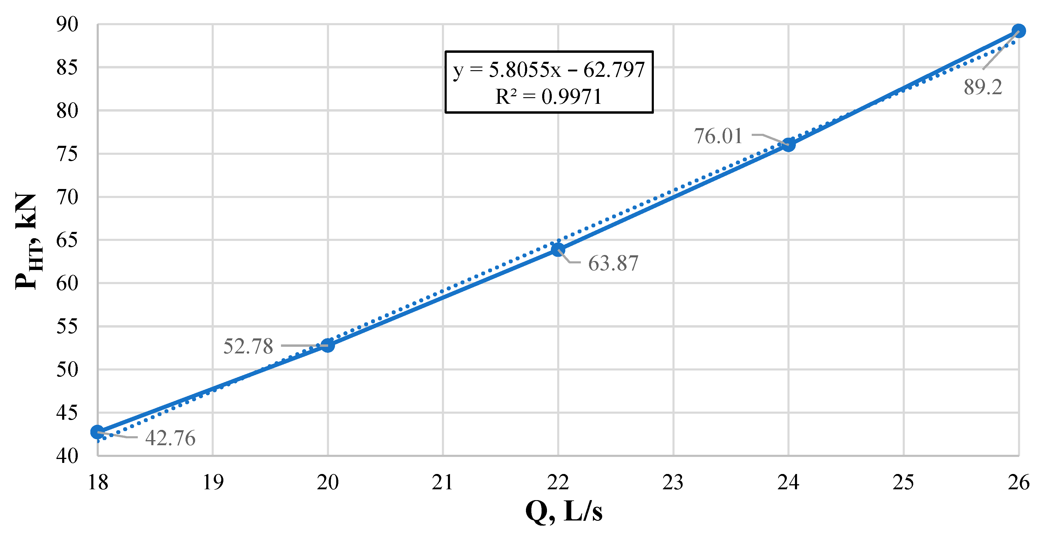
The dependence of the WOB on the pressure drop has a linear form since, in Equation (22), the pressure drop is an argument of the first degree, therefore, with an increase in the pressure drop, the WOB will also grow monotonically. Thus, when the pressure drop changes from 1 to 2 kN, the WOB changes linearly from 35 to 65 kN.
3.
The dependence of the WOB on the flow rate of the drilling mud (Figure 12).
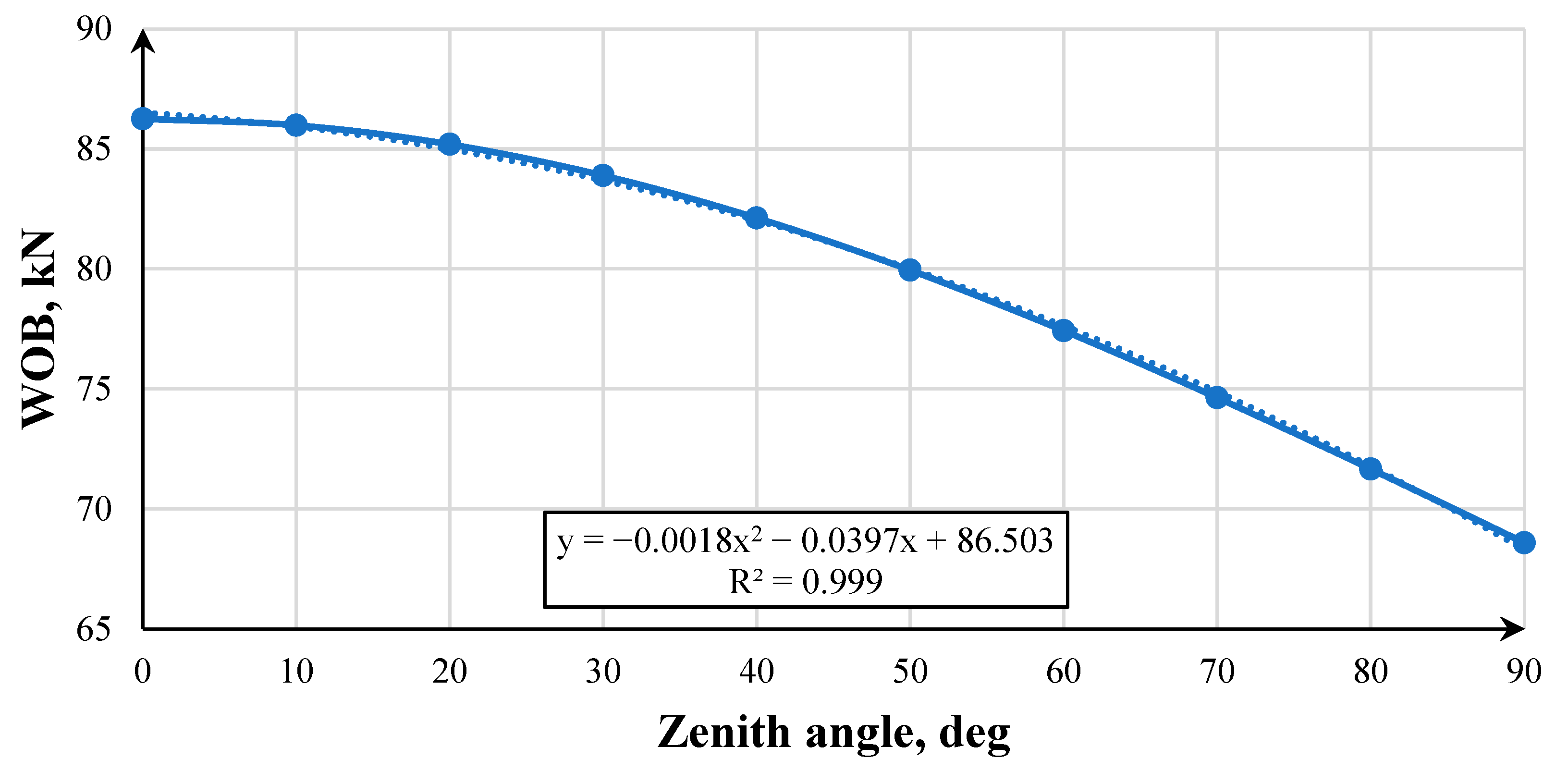
The dependence of the WOB on the consumption of drilling fluid is an important characteristic when using a hydraulic thrusting device. As a result of mathematical modeling, it was found that the dependence is quadratic since, in Equations (3), (8), and (9), the flow rate is the argument of the second degree when calculating the pressure drop, and the pressure drop, in turn, is the argument of the first degree when calculating the WOB. With a further increase in the flow rate of the drilling mud, the WOB will also increase according to a quadratic dependence. Figure 12 shows that when the drilling fluid flow rate changes from 10 to 20 L/s, the WOB changes from 32.5 to 73 kN.
4.
The dependence of the WOB on the zenith angle (Figure 13).
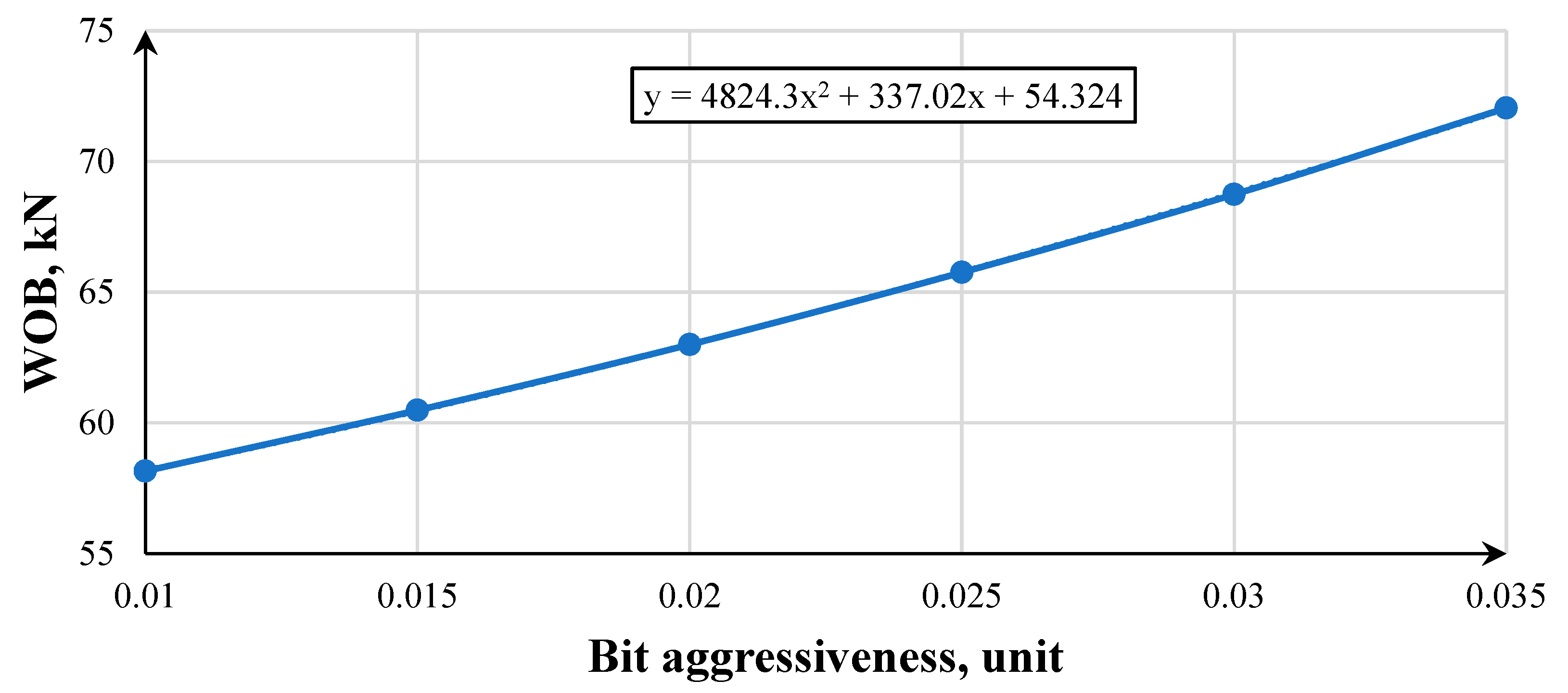
Based on Figure 13, it can be seen that the zenith angle is an argument of the sinusoidal function since the calculation of (17) uses the sum of the projection of the BHA weight on the vertical axis and the load created by the hydraulic thrusting device. Thus, when drilling a vertical well with the given initial data, the WOB will be 86.5 kN, and when drilling a horizontal well, it will be 68.5 kN.
5.
The dependence of the WOB on the bit aggressiveness (Figure 14).
The dependence of the WOB on the aggressiveness of the bit has a form close to linear since, in Equations (21)–(23), the aggressiveness of the bit is an argument of the first degree. From Figure 14, it follows that with an increase in the aggressiveness of the bit, the WOB also increases linearly. Thus, when drilling with a bit with an aggressiveness index of 0.01, the WOB will be 58 kN, and when drilling with a bit with an aggressiveness index of 0.035, it will be 72 kN.
Figure 9, Figure 10, Figure 11, Figure 12 and Figure 13 show that the described values are amenable to polynomial dependencies, which indicates the simplicity of predicting and controlling the hydraulic thrusting device. The operation of the device will also have a significant impact on the complex distribution of the flow in the internal cavity of the hydraulic thrusting device due to its complex geometric shape.
After modeling and building the “Hydraulic thrusting device—Downhole motor—Bit” system, the results were validated by setting up a computational experiment in the AnSYS Workbench program using a direct numerical simulation of the process of the system functioning by the finite element method with a grid frequency of 12,642,971 elements and a tetrahedron type. (Figure 15) [40,41].
According to the simulation results, it can be noted that along the length of the hydraulic thrusting device, the velocity changes by approximately two times (for example, at a flow rate of 26 L/s, the velocity in the upper part of the hydraulic thrusting device is 1715 m/s, and in the lower part—3122 m/s): the drilling mud has the minimum velocity at the top of the device and the maximum velocity at the bottom. With an increase in the flow rate of the drilling mud, its velocity also increases (for example, at a flow rate of 18 L/s, the maximum fluid flow rate is 2161 m/s, and at a flow rate of 26 L/s—3122 m/s), while the dependence is not directly proportional. As well as the velocity, the WOB created by the device increases; this dependence is close to directly proportional (Figure 16) and is identical to the dependence shown in Figure 12.
The main load on the piston of the hydraulic thrusting device, and as a result, on the bit, is due to the pressure of the process fluid on two surfaces, one of which is perpendicular, and the second is inclined by 45 deg. to the direction of flow. To check the results of the mathematical calculation in the Python software, two surface data are given inside the device in order to find the pressure of the moving fluid exerted on them (Figure 17).
Based on the results of the calculation, the average value of the pressure acting on two sites is obtained—1.78 MPa. The average value of the WOB created by the piston of the hydraulic thrusting device is found by:
F = p · S 1 + S 2 · c o s 45 = 1.78 · 1 0 6 · 0.01 + 0.029 = 69.4   kN ,
where
  • S 1 —area of the perpendicular platform, m2.
  • S 2 —area of the site inclined at an angle of 45° to the flow of drilling mud, m2.
  • p —average value of pressure acting on two sites, Pa.
Thus, based on this result, we can conclude that the mathematical calculation in Python 3.10 and the simulation in AnSYS show high convergence. With identical initial data, the resulting WOB created by a hydraulic thrusting device in physical and mathematical modeling is 72.7 kN, and in the AnSYS Workbench simulation, it is 69.4 kN. The difference of 4.5% is due to taking into account all the details of the complex geometry of the internal cavity of the hydraulic thrusting device. The difference in the results of calculations is due to the fact that in mathematical modeling, an iterative calculation of the “Hydraulic Thrusting Device—Downhole Motor—Bit” system was used, during which the increase in the pressure drop across the downhole motor was taken into account, which caused an increase in the WOB created by the hydraulic thrusting device.
When calculating the average position of the piston, the distributions of pressures and velocities along the length of the hydraulic thrusting device were obtained (Figure 18 and Figure 19). Additionally, a graph of the flow rates of the drilling liquid along the length of the hydraulic thrusting device was constructed (Figure 20).
In the range of 0–163 mm, a gradual increase in the fluid flow velocity in the body of the hydraulic thrusting device from 4.7 to 5.2 m/s is seen. In the range of 163–232 mm, a sharp increase to 14.2 m/s is associated with a decrease in the flow area in the body of the hydraulic thrusting device. Further, in the range of 232–360 mm, the speed drops to a value of 3.8 m/s in the form of an increase in the flow section of the hydraulic thrusting device. In the interval from 360 to 1890 mm, a gradual increase up to 5.7 m/s is observed. In the interval from 1890 to 1910 mm, there is a sharp increase to 9.1 m/s due to a decrease in the flow area. Then, in the interval from 1910 to 2087 mm, the velocity decreases to 8.8 m/s. From 2087 to 2119 mm, there is a sharp increase in velocity to 14.8 m/s due to a decrease in the flow area. From 2119 to 2159 mm, a sharp drop in velocity to 8.9 m/s occurs due to an increase in the flow area. In the interval from 2159 to 4450 mm, the velocity gradually decreases from 8.9 to 7.2 m/s.
The pressure on the piston of the hydraulic thrusting device in the middle position is 1.9 MPa, which, when converted into WOB, is 8 tons.
The simulation of the operation of a hydraulic thrusting device with a fully closed and fully open piston was carried out. The results are presented in Figure 20 and Figure 21.
Fully closed position:
Figure 20. Pressure and velocity distribution.
Energies 16 03759 g020
Fully open position:
Figure 21. Pressure and velocity distribution.
Energies 16 03759 g021
Figure 20 and Figure 21 show the simulation results of the operation of the device in the fully closed and fully open positions. Comparing the results obtained, it can be seen that the pressure inside the chamber in the fully open position (2001 kPa) is less than in the fully closed position (2037 kPa). However, the flow rate in the fully open position is greater. Based on this, we can conclude that the design of the device allows for self-regulation of the piston position. In the fully open position, the pressure is less, therefore the reaction force of the drilled soil will tend to return the piston to the middle position. In the fully closed position, the pressure is higher, therefore it will push the piston to the middle position.

4. Discussion

The optimal mode of operation of the device is considered to be such a mode in which the piston is in a floating state with a departure from the neutral point within 500 mm. With this mode of operation, the optimal distance to the extreme positions of the piston is achieved and the operation of the layout with a rigid clutch is completely eliminated.
To monitor the operation of the hydraulic thrusting device, a graph of the pressure drop at the pumps is used. To determine the extreme positions of the piston, protrusions are made on the choke, spear, and the piston. When approaching the extreme positions (the piston moves away from the neutral position by more than 500 mm), the protrusions coincide with each other and the area of the flow section of the drilling fluid decreases, which leads to an increase in the pressure drop at the pumps. This pressure drop jump will be visible on the pressure drop charts. To continue working in the optimal mode, it is necessary to recalculate the operating parameters of drilling according to the algorithm presented in the work.
If the piston takes extreme positions, the impact of vibration loads on the BHA increases. Vibration and beating negatively affect the dynamic balance of the BHA and can lead to the fatigue failure of its components (vibrations over 110 g are critical).
An example is two cases of the destruction of drilling equipment during drilling in rotary mode (destruction of the tube in the borehole device and destruction of the connecting node of the resistivimeter). The vibrations had a peak character (shock pulse) and significantly exceeded 110 g. Financial losses due to equipment failure due to high-vibration loads have been seen to amount to 5–10% of total drilling costs [42,43,44].
When assembling the BHA, it is recommended to install the device directly above the downhole motor (Figure 9), as a different sequence may lead to a decrease in the overall rigidity of the BHA.
The hydraulic thrusting device can find its application, including when drilling wells with a large deviation from the vertical, in bringing the WOB to the bottom [21] as well as working in combination with a PDC bit when drilling in hard rocks in order to reduce the vibration effect on the DS [45,46].

5. Conclusions

Based on the results of the work carried out, the following conclusions can be drawn:
-
The expediency of using hydraulic thrusting devices in the practice of drilling wells with the possibility of forecasting and the operational regulation of the parameters of the operation of the “Hydraulic Thrusting Device—Downhole Motor—Bit” system is confirmed. The calculation performed shows the ability of the device to create the necessary WOB when drilling with a PDC bit in medium rock, amounting to 72.7 kN.
-
A mathematical model was built based on the method of simple iterations and implemented in the Python environment, allowing for predicting the operating modes of a hydraulic thrusting device together with a downhole motor and a PDC bit. The results of the mathematical modeling show high convergence.
-
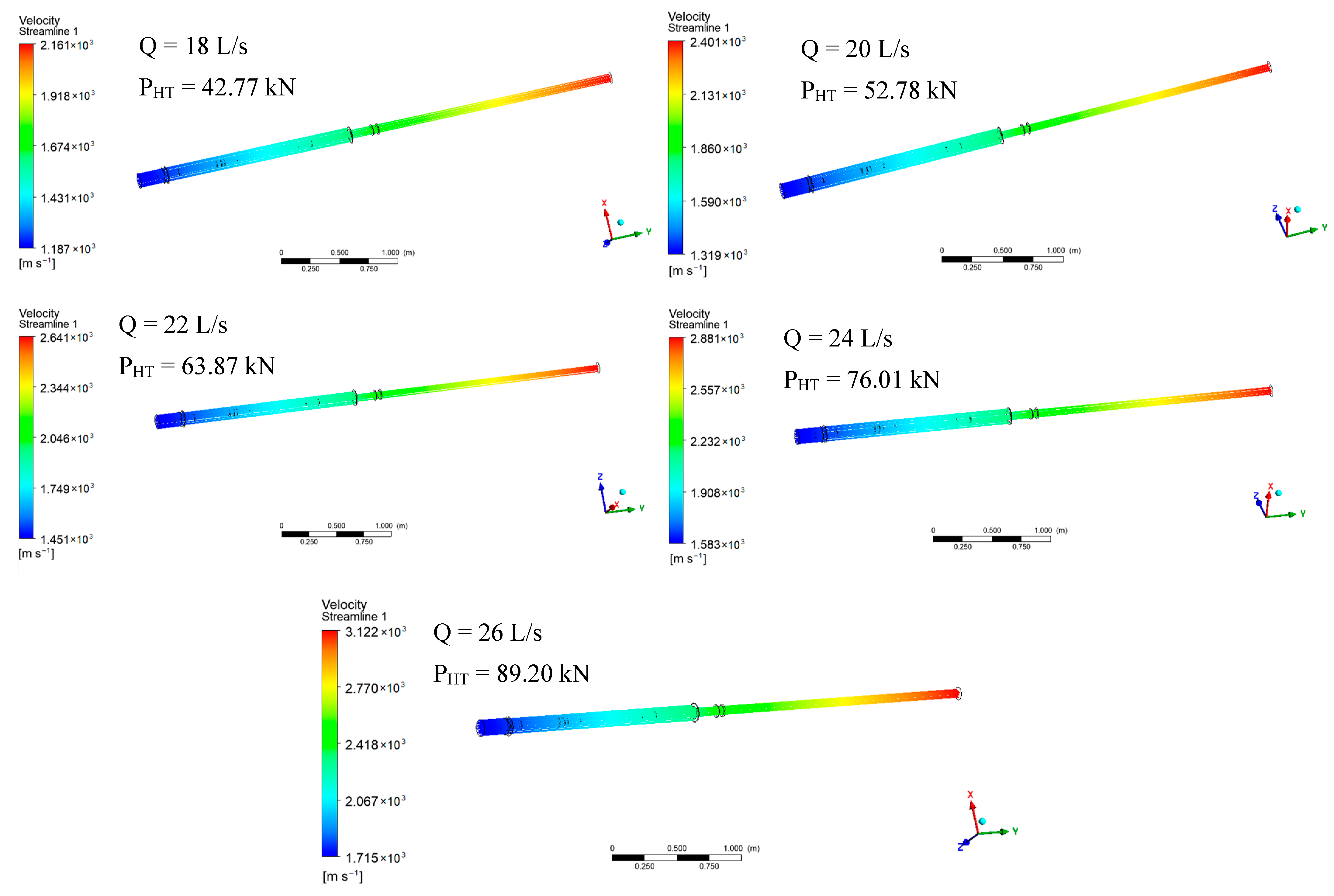
A mathematical calculation and computer simulation showed that the hydraulic thrusting device with a flow rate of drilling fluid in the range of 18–26 L/s is capable of creating a WOB in the range of 43 to 89 kN. The dependence of the WOB and drilling fluid flow rate is described by the equation shown in Figure 12. In addition, the simulation showed the versatility of the design of the hydraulic thrusting device, i.e., replacing the nozzle on the choke spear allows for a change in the WOB created by the thruster.
-
Based on the results of the modeling, a smooth increase in the WOB from 68.1 kN to 72.7 kN from the moment the mud pumps are turned on is theoretically substantiated and proved. The reason for this is a gradual decrease in the reactive moment on the bit. These dependencies are described in Equations (21) and (22), from which the values of the pressure drop of 2.22 MPa and the moment of 578 N · m were obtained.
-
The achieved results make it possible to determine the optimal drilling parameters when using a hydraulic thrusting device. When working directly in the field, it is assumed that there is software that provides the monitoring of the parameters of the device in a system with a downhole motor and a bit. Of particular importance is the monitoring of the pressure drop. If the positions of the protrusions on the instruments at the wellhead coincide, a rapid increase in the pressure drop by 2–3 times will be noticeable, characterizing the approach of the piston to one of the extreme positions. In this case, the field engineer should use the developed algorithm to determine the optimal operating parameters in changing geological and technological conditions.
-
To reproduce the described mathematical model, it is necessary to have the characteristics of the hydraulic thrusting device used, the downhole motor, and the bit, as well as the initial conditions of the experiment (torque on the bit, the WOB without taking into account the pressure of the hydraulic thrusting device, and the initial pressure drop in the system with the downhole motor immobilized). Further, it is necessary to apply the method of simple iterations for Equations (2), (21), and (22) until the changes in the drilling parameters become insignificant. Lastly, it is recommended to validate the obtained results in the AnSYS software environment.

Author Contributions

Conceptualization, M.R. and A.A.K.; methodology, A.A.K. and G.V.B.; software, D.S.U.; validation, A.A.K., M.R. and G.V.B.; formal analysis, A.A.K. and D.S.U.; investigation, A.A.K. and D.S.U.; resources, M.R. and D.I.S.; data curation, M.R. and G.V.B.; writing—original draft preparation, A.A.K. and D.S.U.; writing—review and editing, A.A.K. and D.S.U.; visualization, A.A.K. and D.S.U.; supervision, M.R. and G.V.B.; project administration, A.A.K. All authors have read and agreed to the published version of the manuscript.

Funding

This research received no external funding.

Data Availability Statement

Not applicable.

Conflicts of Interest

The authors declare no conflict of interest.

References

  1. Litvinenko, V.; Dvoinikov, M. Methodology for determining the parameters of drilling mode for directional straight sections of well using screw downhole motors. J. Min. Inst. 2020, 241, 105. [Google Scholar] [CrossRef]
  2. Vadetskiy, U. Drilling of Oil and Gas Wells; Publishing Center «Akademia»: Moscow, Russia, 2003. Available online: https://www.geokniga.org/bookfiles/geokniga-yuv-vadeckiy-burenie-neftyanyh-i-gazovyh-skvazhin.pdf (accessed on 15 March 2023).
  3. Serbin, D.; Dmitriev, A. Experimental research on the thermal method of drilling by melting the well in ice mass with simultaneous controlled expansion of its diameter. J. Min. Inst. 2022, 257, 833–842. [Google Scholar] [CrossRef]
  4. Bolshunov, A.; Vasilev, D.; Ignatiev, S.; Dmitriev, A.; Vasilev, N. Mechanical drilling of glaciers with bottom-hole scavenging with compressed air. Ice Snow 2022, 62, 35–46. (In Russian) [Google Scholar]
  5. Litvinenko, V.; Petrov, E.; Vasilevskaya, D.; Yakovenko, A.; Naumov, I.; Ratnikov, M. Assessment of the role of the state in the management of mineral resources. J. Min. Inst. 2022, 259, 95–111. [Google Scholar] [CrossRef]
  6. Bogdanov, N. The Deepest Wells of Bashkiria; Bashkir Book Publishing House: Ufa, Russia, 1968. [Google Scholar]
  7. Shahnazarov, A. Pneumatic Control of the Drilling Rig—Kapelushnikov-Zalkin’s Console. Oil Ind. 1936, 8. Available online: https://oil-industry.net/pdf/1936/08/31_shakhnazarov.pdf (accessed on 15 March 2023).
  8. Danielyan, A.; Rustambekov, A. Test Results of the Hydraulic Bit Feed Controller of the Olovyanov and Gritsai System. Oil Ind. 1939, 8. Available online: https://oil-industry.net/pdf/1939/08/23_%D0%94%D0%B0%D0%BD%D0%B8%D1%8D%D0%BB%D1%8F%D0%BD.pdf (accessed on 15 March 2023).
  9. Hramenkov, V. Improvement of the Drilling Process and Drilling Equipment: Automation of Control of Technological Processes of Drilling Oil and Gas Wells; Profobrazovanie: Saratov, Russia, 2019. Available online: https://avidreaders.ru/read-book/avtomatizaciya-upravleniya-tehnologicheskimi-processami-bureniya-neftegazovyh-1.html (accessed on 15 March 2023).
  10. Aarsnes, J.; Auriol, J.; Di Meglio, F.; Shor, R. Estimating friction factors while drilling. J. Pet. Sci. Eng. 2019, 179, 80–91. [Google Scholar] [CrossRef]
  11. Tretyak, A.; Lirkevich, Y.; Borisov, K. Effect of Torsional and Longitudinal Vibrations on Drilling Rate and Formation of Breakage of Cutting Elements of Drill Bits Reinforced with PDC. Bulletin of the Tomsk Polytechnic University, 2019. Available online: https://www.mgri.ru/science/scientific-and-innovative-activity/dissertation-council/download/Dissertation_Borisov_K.V.pdf (accessed on 15 March 2023).
  12. Simonyants, S.; Al Taee, M. Stimulation of the Drilling Process with the Top Driven Screw Downhole Motor. J. Min. Inst. 2019, 238, 438. [Google Scholar] [CrossRef] [Green Version]
  13. Galkin, S.; Kochnev, A.; Zotikov, V. Estimate of Radial Drilling Technology Efficiency for the Bashkir Operational Oilfields Objects of Perm Krai. J. Min. Inst. 2019, 238, 410. [Google Scholar] [CrossRef]
  14. Kadochnikov, V.; Dvoynikov, M. Development of Technology for Hydromechanical Breakdown of Mud Plugs and Improvement of Well Cleaning by Controlled Buckling of the Drill String. Appl. Sci. 2022, 12, 6460. [Google Scholar] [CrossRef]
  15. Cebeci, M.; Kök, M. Analysis of sinusoidal buckling of drill string in vertical wells using finite element method. In Proceedings of the SPE Middle East Oil and Gas Show and Conference, OnePetro 2019, Manama, Bahrain, 18–21 March 2019. [Google Scholar] [CrossRef]
  16. Badretdinov, T.; Yamaliev, V. Analysis of drill string vibrations and utilization damping device. Oil Gas Bus 2016. Available online: http://ogbus.ru/files/ogbus/issues/6_2016/ogbus_6_2016_p5-22_BadretdinovTV_ru.pdf (accessed on 15 March 2023). [CrossRef] [Green Version]
  17. Ximao, L.; Jiaqi, Z.; Qiaojuan, G.; Chunying, F.; Yidi, S.; Ruoxi, Z. Hydraulic Thrusters. Pet. Sci. Technol. Forum 2016, 35, 87–90. [Google Scholar]
  18. Van, T.N. An extensive solution to prevent wax deposition formation in gas-lift wells. J. Appl. Eng. Sci. 2022, 20, 264–275. [Google Scholar] [CrossRef]
  19. Zifeng, L.; Changjin, W. Bit feed principles and operations of slide drilling. J. Pet. Sci. Eng. 2017, 152, 505–510. [Google Scholar] [CrossRef]
  20. Minin, A.; Pogarskiy, A.; Chefranov, K. Downhole Machine. Russian Patent SU121733A1, 15 December 1958. Available online: https://yandex.ru/patents/doc/SU121733A1_19590101 (accessed on 15 March 2023).
  21. Reich, M.; Hoving, P.; Makohl, F. Drilling Perfomance Improvements Using Downhole Thrusters. In Proceedings of the SPE/IADC Drilling Conference, Amsterdam, The Netherlands, 28 February–2 March 1995. [Google Scholar] [CrossRef]
  22. Buslaev, V.; Buslaev, G.; Loujikov, D.; Kuznetsov, N.; Gorbikov, A.; Manuilov, A.; Nester, N.; Milenkiy, A. Results of testing the multifunctional downhole bit feeder ZUPD-195. Constr. Oil Gas Wells Land Sea 2007, 11, 32–34. [Google Scholar]
  23. Peng, Y.; Zhang, H. Vibration evaluation and parameter optimization of hydraulic thruster. In Proceedings of the SPIE 10322, Seventh International Conference on Electronics and Information Engineering 2017, Nanjing, China, 17–18 September 2016; Volume 103223. [Google Scholar] [CrossRef]
  24. Jianjun, Z.; Xiaojie, C. Design and field test of hydraulic thruster. IOP Conf. Ser. Earth Environ. Sci. 2020, 558, 022067. [Google Scholar] [CrossRef]
  25. Bashir, M.; Abdesalam, N.; Abugharara, M.; Stephen, D. CFD Numerical Simulation for Downhole Thruster Perfomance Evaluation. In Proceedings of the ASME 2018, 37th International Conference on Ocean, Offshore and Arctic Engineering OMAE 2018, Madrid, Spain, 17–22 June 2018. [Google Scholar] [CrossRef]
  26. Tsirel’, S. Phenomenon of dilatancy in fragmented rocks. J. Min. Inst. 2011, 190, 176. Available online: https://pmi.spmi.ru/index.php/pmi/article/view/6445 (accessed on 15 March 2023).
  27. Gee, R.; Hanley, C.; Hussain, R.; Canuel, L.; Martinez, J. Axial Oscillation Tools vs. Lateral Vibration Tools for Friction Reduction—What’s the Best Way to Shake the Pipe? In Proceedings of the SPE/IADC Drilling Conference and Exhibition, London, UK, 17–19 March 2015. [Google Scholar] [CrossRef]
  28. Al ali, A.; Barton, S.; Mohanna, A. Unique Axial Oscillation Tool Enhances Perfomance of Directional Tools in Extended Reach Applications. In Proceedings of the SPE Brasil Offshore, Macae, Brazil, 14–17 June 2011. [Google Scholar] [CrossRef]
  29. Maidla, E.; Haci, M.; Jones, S.; Cluchey, M.; Alexander, M.; Warren, T. Field Proof of the New Sliding Technology for Directional Drilling. In Proceedings of the SPE/IADC Drilling Conference, Amsterdam, The Netherlands, 23–25 February 2005. [Google Scholar] [CrossRef]
  30. Dvoynikov, M. Technology of Drilling Oil and Gas Wells with Upgraded Screw Downhole Engines: Scientific Generalization, Research Results and Implementation—Diss. for the deg. D.Eng. 2011. Available online: https://www.geokniga.org/books/14667 (accessed on 15 March 2023).
  31. Baldenko, D.; Baldenko, F.; Tchaikovskiy, G. Theory and methodology for calculating a hydraulic thruster when drilling with downhole motors. Drill. Oil 2018. Available online: https://burneft.ru/archive/issues/2018-10/36 (accessed on 15 March 2023).
  32. Sultanov, B.; Shammasov, N. Downhole Drilling Machines and Tools; Nedra: Moscow, Russia, 1976. [Google Scholar]
  33. Gerasimova, I.G.; Oblova, I.S.; Golovina, E.I. The Demographic Factor Impact on the Economics of the Arctic Region. Resources 2021, 10, 117. [Google Scholar] [CrossRef]
  34. Lyagov, I.; Baldenko, F.; Lyagov, A.; Yamaliev, V.; Lyagova, A. Methodology for calculating technical efficiency of power sections in small-sized screw downhole motors for the «Perfobur» system. J. Min. Inst. 2019, 240, 694. [Google Scholar] [CrossRef]
  35. Nikolaev, A.; Zaripova, N. Substantiation of analytical dependences for hydraulic calculation of high-viscosity oil transportation. J. Min. Inst. 2021, 252, 885–895. [Google Scholar] [CrossRef]
  36. Loseva, E.; Lozovsky, I.; Zhostkov, R.; Syasko, V. Wavelet Analysis for Evaluating the Length of Precast Spliced Piles Using Low Strain Integrity Testing. Appl. Sci. 2022, 12, 10901. [Google Scholar] [CrossRef]
  37. Trushkin, O.; Akchurin, H. PDC cutter pressure on plastic-brittle rock in the process of its destruction. J. Min. Inst. 2020, 244, 448–453. [Google Scholar] [CrossRef]
  38. Leonov, E.; Simonyants, S. Improvement of the Technological Process of Well Deepening; Publishing Center of Gubkin University: Moscow, Russia, 2014. Available online: https://www.geokniga.org/bookfiles/geokniga-sovershenstvovanie-tehnologicheskogo-processa-uglubleniya-skvazhiny.pdf (accessed on 15 March 2023).
  39. Rybak, J.; Khayrutdinov, M.; Kuziev, D.; Kongar-Syuryun, C.; Babyr, N. Prediction of the geomechanical state of the rock mass when mining salt deposits with stowing. J. Min. Inst. 2022, 253, 61–70. [Google Scholar] [CrossRef]
  40. Choupani, M.; Tabatabaee Moradi, S.S.; Tabatabaei Nejad, S.A. Study on Attapulgite as Drilling Fluid Clay Additive in Persian Gulf Seawater. Int. J. Eng. 2022, 35, 587–595. [Google Scholar] [CrossRef]
  41. Wujun, X.; Derong, Z.; Simeng, W.; Yangfeng, P. Simulation and Analysis on Flow Field of Nozzle Position of Hydraulic Thruster Based on CFD. Interntational J. Sci. Res. 2018, 7, 2319–7064. [Google Scholar] [CrossRef]
  42. Scherbakova, K.; Ovezov, B.; Kalendarova, L.; Kuznetsova, D. Cause of Vibration during Drilling. Neftegaz.Ru 2022. Available online: https://magazine.neftegaz.ru/articles/burenie/756505-analiz-vozniknoveniya-vibratsiy-v-protsesse-bureniya/ (accessed on 15 March 2023).
  43. Dvoynikov, M.; Sidorov, D.; Kambulov, E.; Rose, F.; Ahiyarov, R. Salt Deposits and Brine Blowout: Development of a Cross-Linking Composition for Blocking Formations and Methodology for Its Testing. Energies 2022, 15, 7415. [Google Scholar] [CrossRef]
  44. Burkhanov, R.N.; Lutfullin, A.A.; Maksyutin, A.V.; Raupov, I.R.; Valiullin, I.V.; Farrakhov, I.M.; Shvydenko, M.V. Algorithm of retrospective analysis for identification and localization of residual reserves of the developed multi-layer oil field. Georesursy 2022, 24, 125–138. [Google Scholar] [CrossRef]
  45. Tsyglianu, P.P.; Romasheva, N.V.; Fadeeva, M.l.; Petrov, I.V. Engineering projects in the russian fuel and energy complex: Actual problems, factors and recommendations for development. Ugol 2023, 3, 45–51. (In Russian) [Google Scholar] [CrossRef]
  46. Duryagin, V.; Nguyen Van, T.; Onegov, N.; Shamsutdinova, G. Investigation of the Selectivity of the Water Shutoff Technology. Energies 2023, 16, 366. [Google Scholar] [CrossRef]
Figure 1. Timing of the issuance of copyright certificates and patents from 1970 to 2020 in the Soviet Union and Russia.
Energies 16 03759 g001
Figure 2. Dependences of RPM and torque on pressure drop.
Energies 16 03759 g002
Figure 3. Drawing of the hydraulic thrusting device: (a)—fully closed posistion of the piston; (b,c)—intermediate positions of the piston; (d)—fully open position of the piston.
Energies 16 03759 g003
Figure 4. Three-dimensional model of the assembly of a section of the hydraulic thrusting device.
Energies 16 03759 g004
Figure 5. Diaphragm and sleeve inside the choke spear.
Energies 16 03759 g005
Figure 6. The shape of the internal chamber of the hydraulic thrusting device with zero displacements of the piston.
Energies 16 03759 g006
Figure 7. Introduction of the Cartesian coordinate system.
Energies 16 03759 g007
Figure 8. Cross-section of the choke spear and piston.
Energies 16 03759 g008
Figure 9. Scheme of the action of forces on the BHA.
Energies 16 03759 g009
Figure 10. Graph of the dependence of the pressure drop on the flow rate.
Energies 16 03759 g010
Figure 11. Graph of the dependence of the WOB on the pressure drop.
Energies 16 03759 g011
Figure 12. Dependence of the WOB on the flow.
Energies 16 03759 g012
Figure 13. Dependence of the WOB on the zenith angle (a solid line—experimental data; a dotted line—a trend line).
Energies 16 03759 g013
Figure 14. Graph of the dependence of the WOB on the aggressiveness of the bit (a solid line—experimental data; a dotted line—a trend line).
Energies 16 03759 g014
Figure 15. Hydrodynamic modeling of the hydraulic thrusting device in AnSYS Workbench.
Energies 16 03759 g015
Figure 16. Graph of the dependence of the WOB on the consumption of drilling fluid (a solid line—experimental data; a dotted line—a trend line).
Energies 16 03759 g016
Figure 17. The pressure exerted on platforms inclined to the flow at 90 and 45 deg.
Energies 16 03759 g017
Figure 18. Pressure and velocity distribution.
Energies 16 03759 g018
Figure 19. The flow rate of the drilling fluid along the length of the hydraulic thrusting device.
Energies 16 03759 g019
Table 1. Initial data for calculation.
Initial DataDesignationValue
Parameters related to the drilling process
Drilling mud consumption, L/sQ26
Drilling mud density, kg/m3 ρ 1100
Inclination angle, ° α 75
Parameters of hydraulic thrusting device
Weight of hydraulic thrusting device, kg m H T 457
Hydraulic thrusting device piston diameter, mm d H T 170
Choke spear diameter, mm d C S O 55
Piston stroke length, mm l P S 1600
Inner diameter of the choke spear nozzle, mm d C S i 17
Number of diaphragm holes, units n D H 12
Diameter of diaphragm openings, mm d D H 20
Upper adapter inner diameter, mm d T S 127
Piston projection surface area, cm2 f P P 30.8
Downhole motor parameters
Downhole motor weight, kg m H D M 1000
Downhole motor pressure drop, kPa p H D M 482.6
Bit parameters
Bit weight, kg m b i t 65
Bit diameter, mm d b i t 215.9
Number of bit nozzles, units n B N 6
Bit jet nozzles diameter, mm d N D 12
Table 2. Iterative process.
Iteration Number iTorque M, N · mWOB, kNWOB Increment ΔP, N
141168.113,654
251571.53424
354172.4859
454772.7215
554972.754
Table 3. Calculation result.
ParameterUnit of MeasurementValue
Torque N · m 578
Pressure dropMPa2.22
WOBkN72.7
Drilling mud densitykg/m31100
Drilling mud consumptionL/s20
Inclination anglegrad.75
Disclaimer/Publisher’s Note: The statements, opinions and data contained in all publications are solely those of the individual author(s) and contributor(s) and not of MDPI and/or the editor(s). MDPI and/or the editor(s) disclaim responsibility for any injury to people or property resulting from any ideas, methods, instructions or products referred to in the content.

