Article

A Model Independent Predictive Control of PMSG Wind Turbine Systems with a New Mechanism to Update Variables

1
School of Electrical Engineering, Shandong University, Jinan 250061, China
2
State Grid Wuxi Power Supply Company, Wuxi 214000, China
*
Author to whom correspondence should be addressed.
Energies 2023, 16(9), 3764; https://doi.org/10.3390/en16093764
Submission received: 11 March 2023 / Revised: 15 April 2023 / Accepted: 26 April 2023 / Published: 27 April 2023
(This article belongs to the Special Issue Energy, Electrical and Power Engineering 2021-2022)

Abstract

:
Permanent magnet synchronous generator (PMSG) wind power system with full power rating converter configuration is especially suitable for wind energy applications. Direct model predictive control (DMPC) has led to more possibilities in terms of choice because of its straightforward concept for PMSG wind turbine systems in high-power off-shore wind farms. However, due to complete dependence on the model knowledge, parameter mismatches will seriously deteriorate the system control performances. This work presents a model/parameter-independent predictive control method with a novel mechanism to update current/power variations online. The proposed method makes use of only two measurements from the former intervals and the selected control vectors to estimate all variations of the candidate vectors in the present interval. Benefiting from this updating mechanism, the proposed method is completely independent of the model parameters in the state prediction. However, it still has a very low calculating requirement and smooth current/power variation waveforms. The proposed method is compared with classical DMPC. The results validate that the proposed solution outperforms the classical DMPC with model deviations, with considerably improved robustness.

1. Introduction

Electricity generated by renewable energy has grown significantly since the end of the 20th century. Among the variations, high-power offshore wind energy has become increasingly competitive with other energy sources in terms of rich reserves, long generation time, and “cost-per-generated kilowatt hour” [1,2]. Large-capacity wind turbines have become essential in offshore wind energy installation in the last few years [3]. Permanent magnet synchronous generator (PMSG) with direct-drive configuration has considerable advantages in such a system in terms of higher energy density, gearbox elimination/reduction, and less maintenance [4,5]. As one such configuration, a very potent system based on full power rating back-to-back converter is spreading rapidly for high-power offshore wind energy generation [5]. A simplified circuit diagram of such a PMSG system is introduced in Figure 1. Considering both the nonlinear characters and switching nature of the power converters, the direct model predictive control (DMPC, also called finite-control-set model predictive control, FCS-MPC) is a promising method to implement with multiple-target optimization in a single step [6]. Therefore, DMPC makes the time-averaged modulation stage unnecessary in the control of power converters [7]. It offers fast dynamic performance and a straightforward design. The literature shows that the DMPC has already emerged as a widely-used control option for the system shown in Figure 1 [8,9,10].
Due to the reliance on model-based prediction of system states, DMPC suffers from system model deviations (caused by, e.g., inaccurate modeling and incorrect component parameters) [6,11]. In practice, the considerable mismatches between the values in the actual equipment and the values used in the controller often occur on unavailable (e.g., stator flux) and time-varying parameters (e.g., coil inductance in generator or filter) of the wind energy system. Inaccurate prediction of the system’s future behaviors would result in this situation and induce performance deterioration (e.g., large steady-state tracking bias and increased control variable ripples [12]).
Researchers have proposed several methods to improve the model predictive control’s robustness. Three methods can be grouped as three different concepts. The first concept is observer-based methods [13,14]. In [15,16], an observer for perturbations caused by mismatch was employed in a deadbeat control solution. Reference [17] presents a full parameter disturbance and load observer to simultaneously estimate both electrical and mechanical parameters of PMSG for model predictive speed control. However, observer-based solutions are usually complicated, requiring higher tuning efforts and compromising system stability by adding redundant control loops. The second concept is error compensation [18]. In [19,20], the prediction model compensates for the state tracking bias caused by parameter mismatches, assuming that the prediction error for a given switching state remains unchanged within a few control intervals. In [21], a new cost function in proportional integral (PI) form is designed to eliminate steady-state errors. The improved parameter stability region is theoretically derived. However, since the prediction stage still uses the mismatched parameters, the control performance improvement is not satisfactory under large parameter deviation conditions. The third group is model-free or model-independent predictive control (MIPC) [22]. Reference [23] first presented such a solution for a PMSG drive. Different from the previous two groups of solutions, it designed look-up tables (LUTs) to maintain status variation for a previous control interval as information for the prediction of the system behaviors in the future interval. This eliminates the model information and, therefore, the controller gains greater robustness to significant parameter deviation. Nevertheless, if certain specific voltage vectors have not been applied for multiple control intervals, most of the previously stored current variation information will be outdated and unreliable for future prediction [23,24], resulting in large updating lag. This will significantly affect the control performance, causing unacceptable ripples in the output waveforms and even posing a significant risk to the stability of the system during transient states. Authors of the recent contributions [25] proposed a solution in which previously applied voltage vectors and current measurements are used to estimate the current variation under other voltage vectors to form a smoother updating waveform with less lag. However, such an update mechanism can only be activated when three previously applied voltage vectors differ. Moreover, a total number of 210 switching sequences have to be categorized to seek the optimal one, which significantly increases the computational burden of the controller.
To conquer the problems analyzed above, this paper proposes a new MIPC method based on the estimation of all possible variations to quickly update the LUTs. We validate this method on the control of both the generator and grid sides of a two-level back-to-back converter-based PMSG wind power system. It requires only two measurements from the former intervals and the relevant information regarding control vectors. Compared to the method that only updates the relevant variation of the selected vector, it estimates the necessary state variations for all possible voltage vectors in the present interval. The main contributions of this work include:
  • A new effective model-independent predictive control for both the generator and the grid side of high-power PMSG wind turbine systems is presented (see Section 4). The proposed method is immune to both generator- and grid-side parameter mismatches and model deviations. Robustness improvement of the proposed method outperforms the classical model-based MPC technique (see Section 5.2);
  • A new state variable variation updating mechanism is proposed, which assures smooth current/power variation waveforms and non-lag updating. The proposed solution is analytically developed and requires many fewer online calculations in comparison with the recently reported approaches (see Section 4);
  • The proposed solution is tested in various scenarios (see Section 5), which show promising results in enhanced robustness.
The contents of this article are organized as follows. In Section 2, the basic modeling of the grid-tied two-level back-to-back converter system is presented. Section 3 reviews the classical model-based and model-free methods for such a system, and in Section 4, we introduce the detailed proposed mechanism and the design of the controller. Section 5 reports on the verification and analysis of the proposed method. Finally, Section 6 concludes this paper.

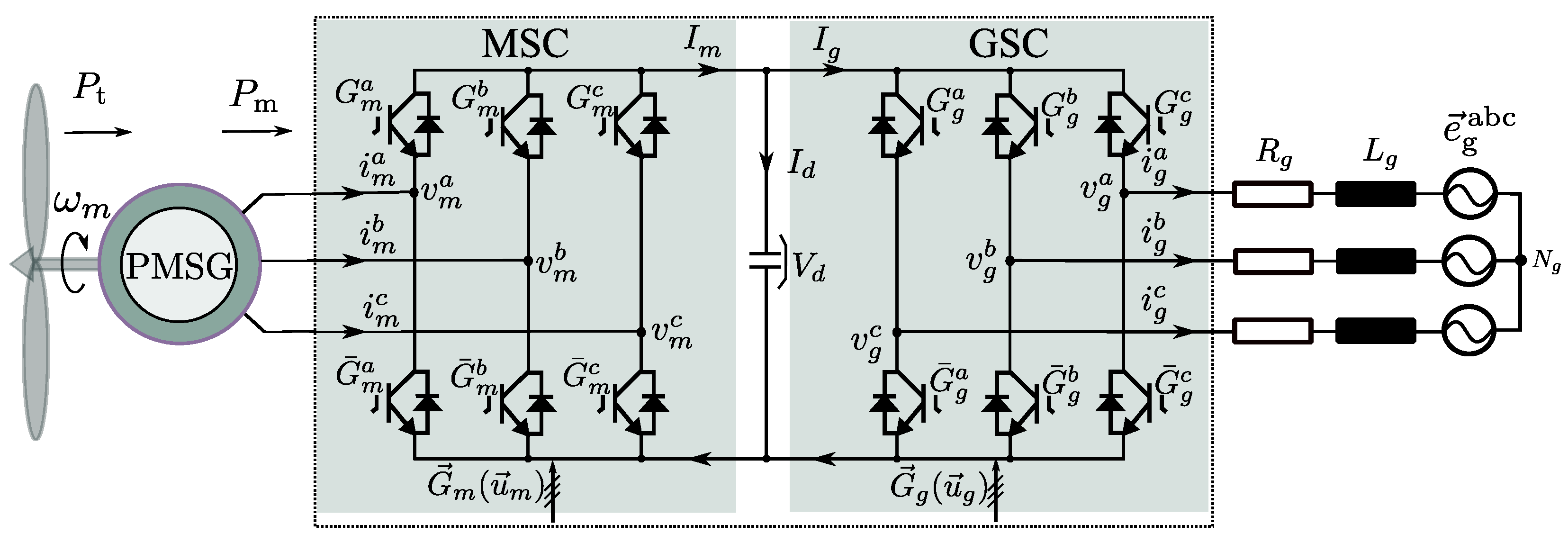
2. System Description and Modeling

A two-level voltage source back-to-back power converter PMSG wind turbine system with direct-drive configuration is presented in Figure 1. A machine-side converter (MSC) and grid-side converter (GSC) are connected by the DC-link capacitor. During normal operation phases, MSC is used as the power interface to control the generator, while GSC aims to regulate the DC-link and grid-side power. The aerodynamics and turbine are modeled in, e.g., ref. [6]. These are not repeated here. Meanwhile, we assume a speed reference ω m * has been obtained as the maximum power point tracking (MPPT) requirement by another external controller which is not the focus of this study. In the following, the generator side, grid side, MSC, and GSC are modeled. Note that variables x α β in the stationary frame and x dq in the rotary reference frame are derived, invoking the corresponding (power invariant) Clarke and Park transformations, respectively.
The current dynamics of the surface-mounted permanent magnet generator (SPMSG) model in rotary reference coordinates can be expressed as
g i m d g i m q = 1 L s v m d v m q R s L s i m d i m q ω e i m q i m d 1 L s 0 ω e · ψ pm ,
where G m = ( g i m d , g i m q ) is the gradient of the PMSG stator currents and v m dq and i m dq denote MSC output voltage and PMSG stator currents in the dq frame, respectively.
Using measured values of the voltage and current from the point of coupling, the instantaneous power is calculated as [26]
P Q = e g α e g β e g β e g α E g i g α i g β .
Power dynamics in stationary coordinates for a balanced grid are
g P g Q = 1 L g E g v g α e g α v g β e g β R g L g P + ω g Q R g L g Q ω g P ,
where G g = ( g P , g Q ) represents the grid-side power gradient and v g α , v g β , and e g α , e g β represent GSC output voltage vectors and grid voltages in the α β frame, respectively.
Introducing G y x as the switch signal for the IGBTs in Figure 1, where y { m , g } and x { a , b , c } , the complementary signal for the opposite IGBTs in the same converter leg can be written as G ¯ y x . The switching state u y x can be defined accordingly as
u y x : = G ( G y x ) = P if : G y x 1 = 1 N if : G y x 1 = 0
for phase x . The 3-phase has 2 3 vector options for each side converter to meet the control requirements, presented as
u y abc = ( u y a , u y b , u y c ) S 8 : = N N N , N N P , , P P N , P P P .
Taking switching states and DC-link voltage V d into consideration, the phase voltages of the converter can be obtained as [27]
v y abc = v y a v y b v y c = V d 3 2 1 1 1 2 1 1 1 2 u y abc .
Known from Figure 1, DC-link voltage depends on the current flow of the MSC and GSC and can be modeled as
d V d ( t ) d t = 1 C I d ( t ) = 1 C I g ( t ) I m ( t ) ,
where I g = i g abc · u g abc and I m = i m abc · u m abc present the DC-link current components of the grid and generator side, respectively.

3. Classical Direct Model Predictive Control Methods

3.1. System Requirements and Cost Function Design

The control objectives for the GSC and MSC in a normal back-to-back converter-based wind turbine system, shown in Figure 1, are listed as (see, e.g., [28]):
  • Torque/current control:The primary torque/current control must have a promising dynamic performance to generate proper reference considering: (a) MPPT of the wind turbine system or (b) suitable torque generation for supercritical wind speed. Stress on the mechanical components needs to be reduced by minimizing torque ripples and current THDs;
  • Complex power control: The GSC must regulate the grid-side complex power quickly and dynamically to reduce fluctuations in the DC link caused by the intermittent feed-in of wind power. To meet the requirements of the Grid Code, a low-current distortion factor should be ensured;
  • DC-link voltage control: A stable DC-link voltage is required for the proper operation of the system;
  • Switching frequency regulation: As the wind turbine power level rises, needed improvement of efficiency at any point requires reducing switching losses by low switching frequencies.
Closely related to these requirements, state variables, i.e., the generator stator current x m = ( i m d , i m q ) and grid power x g = ( P , Q ) are taken into consideration in two cost functions ( y = m for generator side, y = g for grid side), as
J y = x y ( k + 2 ) x y * 2 2 + λ y Δ u y ( k + 1 ) ,
where x 2 is the status of the system x and Δ u y ( k + 1 ) = u y ( k + 1 ) u y ( k ) represents the switching change in this control period. The weighting factor, λ y , is designed for the optimization of multiple control objectives, which consist of the desired status and switching frequency here. For a surface-mounted PMSG wind turbine control, i m d * shall be zero to ensure the maximum torque per ampere (MTPA) control of PMSG. A unity power factor can be achieved by setting Q * as zero in the grid-side control. The outer PI loops calculate the reference i m q * and P * to meet the above requirements of the generator’s speed and DC-link voltage. The delay of the sampling process in the real digital controller can be compensated by introducing the state variables at k + 2 , instead of variables at k + 1 , during the traversal of all possible control vectors [29].

3.2. Classical Direct Model Predictive Control

To get the state variables at the k + 1 instant, the classical DMPC calculates the future stator currents and power for a finite set of voltage vectors by utilizing the system model, as
x y ( k + 1 ) = x y ( k ) + T s · G y ( k ) ,
where y { m , g } , x m is the stator current vector i and x g is the grid power vector S . T s · G y ( k ) denotes the state variation caused by this control interval. The same idea gives the prediction at the k + 2 instant of the state variables as
x y ( k + 2 ) = x y ( k + 1 ) + T s · G y ( k + 1 ) .
The controller selects and records the optimal vector from all control vectors, which minimizes the cost function (8). In the next control interval, this will be applied, and relevant delay compensation will be achieved as mentioned above. This procedure is repeated while new measurements arrive continuously [30]. However, it is observed that prediction of state variables in Equation (10) requires accurate information on the system parameters. The controller will derive the wrong prediction of the system utilizing mismatched parameters, resulting in the selection of the non-optimal control vectors. This has serious effects on the control of the stator current or the grid power until the system no longer functions properly and stably. To this end, we will present model-independent solutions in the following part.

3.3. A Latest Model-Independent Predictive Control Solution

Reference [24] presented an efficient MIPC algorithm for synchronous reluctance motor control. In this work, its principles are extended to the underlying PMSG wind turbine system as a benchmark. The dq-axis stator currents (of PMSG) and complex power (of GSC) variations under different voltage vectors are calculated and stored in four LUTs. The LUTs are updated online with new measurements. The future behavior of the system is calculated using the LUTs’ data as
x y ( k + 1 ) = x y ( k ) + Δ x y ( k ) ,
where Δ x y ( k ) denote the currents (for y = m ) and power variations (for y = g ) caused by the application of the voltage vector at time step k, which is determined in the k − 1 control interval. Δ x y ( k ) is considered the same as the last ones stored in the LUTs. Then the possible status at time step k + 2 is derived as
x y ( k + 2 ) = x y ( k + 1 ) + Δ x y ( k + 1 ) .
The current and power prediction of MIPC is hence accomplished using Δ x y stored in the LUTs, avoiding the use of system parameters.
This is easy to understand because, for a voltage vector that has not been selected during a long period, the stored information will be obsolete, which will influence the prediction accuracy and the control performance. The MIPC in [24] forces the output of this vector that has not been applied for a given time period, regardless of the cost function minimization optimization principle, which results in increased ripple and degraded steady-state performance. An improved MIPC with a new state variable update principle is proposed in the next section.

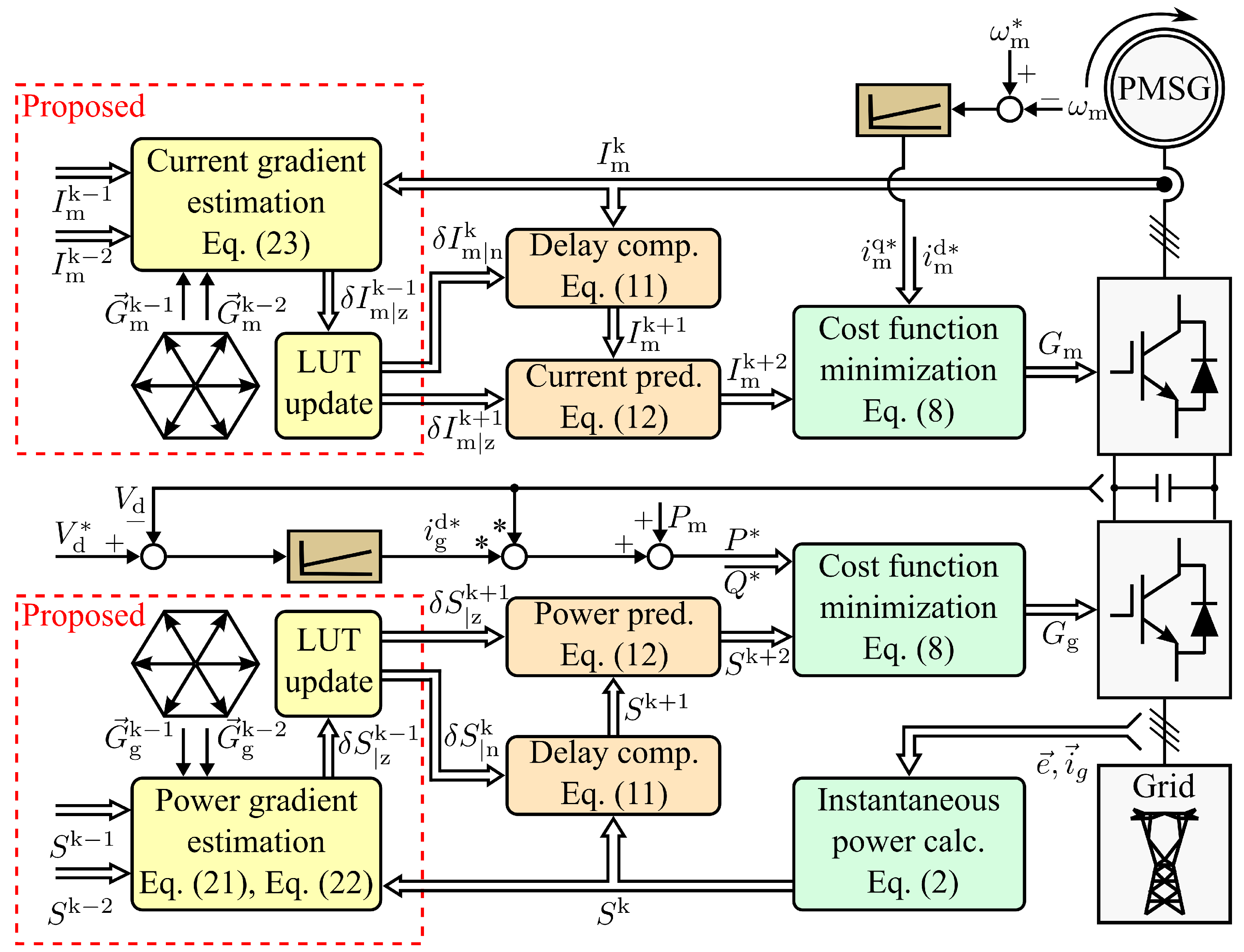
4. Proposed Model-Independent Predictive Control Solution

This section introduces an improved model-independent predictive control method with fast updating look-up tables (LUTs). The overall diagram is given in Figure 2. A grid-side power analysis based on instantaneous power clearly describes the idea of the method. The basis for this begins with a small signal model analysis.

4.1. Small-Signal Modeling of the System

Grid active and reactive power in steady-state is described as
G m = 0 0 = 1 L g E g v g α e g α v g β e g β R g L g P + ω g Q R g L g Q ω g P .
Equation (3) subtracts Equation (13), deriving the small-signal model of the grid side as
g δ P g δ Q = 1 L g E g δ v g α δ v g β R g L g δ P + ω g δ Q R g L g δ Q ω g δ P ,
where ( δ P , δ Q ) = δ S represents the complex power variation and δ v g = v g v g s indicates the relationship between control voltage vectors and the steady-state voltage vector. For instance, δ v g | i = v g | i v g s represents the vector between the steady-state voltage and the ith converter voltage vector.
Converting to discrete form, Equation (14) yields
δ P δ Q = T s L g E g δ v g α δ v g β ,
where T s denotes the sampling interval. Now the small-signal model can be introduced into the controller with measurements of the grid-side voltages. Note that T s · δ S are small enough to be neglected. Similarly, the discrete small-signal model of PMSG can be derived as
δ i m d δ i m q = T s L s δ v m d δ v m q .
The small-signal equations illustrate the relationship between the state variables’ variation and the relevant control vectors. With these equations, the LUTs have the opportunity to update variation caused by all control vectors at the same interval.

4.2. Look-Up Table Update Principle

The steady-state vector v g s can not easily be obtained by the sampling process. The elimination of this vector from the small-signal model (see Equation (15)) relies on the iterative calculation among the converter voltage vectors. Based on Equation (15), two former voltage vectors ( δ v g | k 1 and δ v g | k 2 ) with their relevant power variation ( δ P | k 1 , δ Q | k 1 and δ P | k 2 , δ Q | k 2 ) can be derived as
δ P | k 1 δ P | k 2 δ Q | k 1 δ Q | k 2 = T s L g E g δ v g | i α δ v g | j α δ v g | i β δ v g | j β .
Note that, given δ v g | k 1 = v g | k 1 v g s , δ v g | k 2 = v g | k 2 v g s , we obtain δ v g | k 1 δ v g | k 2 = v g | k 1 v g | k 2 .
Hence, the steady-state vector v g s can be eliminated from Equation (17), and Equation (17) can be rewritten as
δ P | k 1 δ P | k 2 δ Q | k 1 δ Q | k 2 = T s L g E g v g | i α v g | j α v g | i β v g | j β .
Based on Equation (18), the state variations can be derived using information from interval k 1 and k 2 as
Δ P | i ( k 1 ) Δ P | j ( k 2 ) Δ Q | i ( k 1 ) Δ Q | j ( k 2 ) = T s L g E g × v g | i α ( k 1 ) v g | j α ( k 2 ) v g | i β ( k 1 ) v g | j β ( k 2 ) ,
where v g | i ( k 1 ) and v g | j ( k 2 ) are the ith and jth converter vector, which are applied at the k−1 and k−2 instants, respectively; Δ S | i ( k 1 ) = S ( k ) S ( k 1 ) , Δ S | j ( k 2 ) = S ( k 1 ) S ( k 2 ) represent state variation calculated with sampling values.
We then change the special ith vector at k − 1 instant to all vectors ( z th, z { 1 , 2 , , 8 } ) that may be selected, and their relevant power variation can be estimated as
Δ P | z ( k 1 ) Δ P | j ( k 2 ) Δ Q | z ( k 1 ) Δ Q | j ( k 2 ) = T s L g E g × v g | z α ( k 1 ) v g | j α ( k 2 ) v g | z β ( k 1 ) v g | j β ( k 2 ) .
So far, a relationship has been found between the selected voltage vector at the instant k − 2, with its relevant change in complex power, and the possible complex power variation with all candidate control vectors at instant k − 1.
Note that the calculation of Equation (20) still relies on the inductance parameter. To remove this parameter from status estimation, Equations (19) and (20) can be combined and Equations (21) and (22) can be derived, only introducing the control vector applied at instant k − 1 and the corresponding status variation, as
Δ P | z ( k 1 ) = v g | z α ( k 1 ) v g | j α ( k 2 ) e g α + v g | z β ( k 1 ) v g | j β ( k 2 ) e g β v g | i α ( k 1 ) v g | j α ( k 2 ) e g α + v g | i β ( k 1 ) v g | j β ( k 2 ) e g β × Δ P | i ( k 1 ) Δ P | j ( k 2 ) + Δ P | j ( k 2 ) ,
Δ Q | z ( k 1 ) = v g | z α ( k 1 ) v g | j α ( k 2 ) e g β v g | z β ( k 1 ) v g | j β ( k 2 ) e g α v g | i α ( k 1 ) v g | j α ( k 2 ) e g β v g | i β ( k 1 ) v g | j β ( k 2 ) e g α × Δ Q | i ( k 1 ) Δ Q | j ( k 2 ) + Δ Q | j ( k 2 ) .
For the generator side, following a similar theoretical calculation process, stator current variation update equations are estimated using the last two current measurements as
Δ I m | z ( k 1 ) = v m | z dq ( k 1 ) v m | j dq ( k 2 ) v m | i dq ( k 1 ) v m | j dq ( k 2 )                                                                                                                   × Δ I m | i ( k 1 ) Δ I m | j ( k 2 ) + Δ I m | j ( k 2 ) ,
where Δ I m | i ( k 1 ) , Δ I m | j ( k 2 ) are the calculated current variation corresponding to applied vectors v m | i dq ( k 1 ) , v m | j dq ( k 2 ) ; and where Δ I m | i ( k 1 ) = I m ( k ) I m ( k 1 ) , Δ I m | j ( k 2 ) = I m ( k 1 ) I m ( k 2 ) . Δ I m | z ( k 1 ) ( z { 1 , 2 , , 8 } ) denote estimated current variation under all candidate MSC output vectors at instant k 1 .
Furthermore, the denominators in Equations (21)–(23) need to remain non-zero while estimating the status variation update (Equations (21)–(23)). In this work, the LUTs are updated when the denominators in these equations outweigh a certain value. Otherwise, the LUTs maintain as their values the previous interval. By obtaining the variation updating mechanism under all control vectors of back-to-back power converters, the controller guarantees the LUTs’ update frequency and skips updating-lag completely.
The process of this method is summarized as follows. Firstly, the controller obtains the current state value of the system by sampling and calculates the variation between instant k − 2 and k − 1 by reading the value of the previous moment. Secondly, it uses Equations (21)–(23) to update all candidate control vectors with their possible variation in one control interval. Finally, the controller uses the generator side and grid side LUTs instead of the system model to calculate the future stator currents and to power-predict the system variables for the finite set of voltage vectors, completing the compensation and prediction and selecting the optimal vector that minimizes the cost function.

5. Verification

This section investigates the control performances of the proposed MIPC and the classical DMPC, which validate the effectiveness of the proposed method. The system parameters are listed in Table 1.

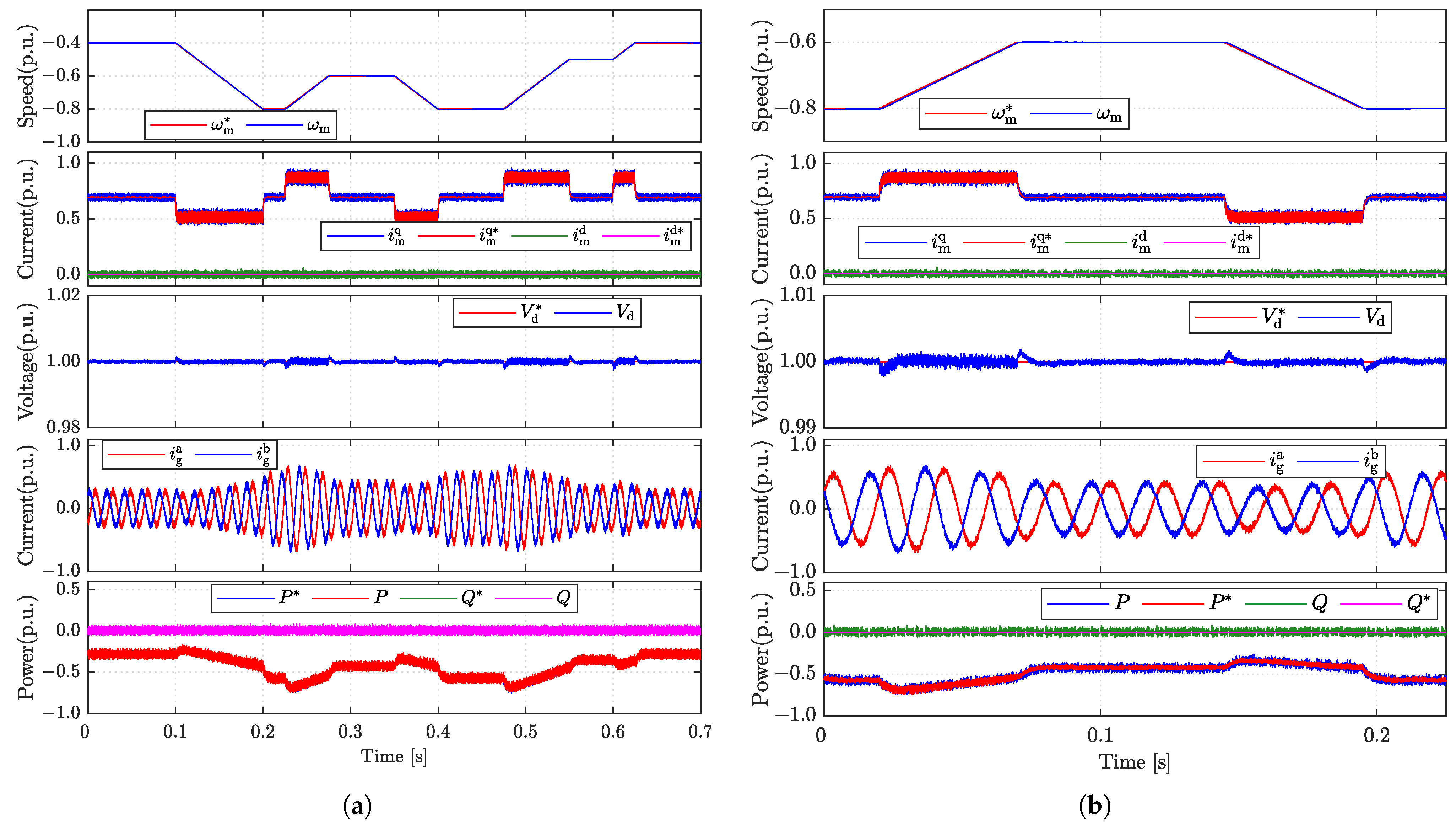
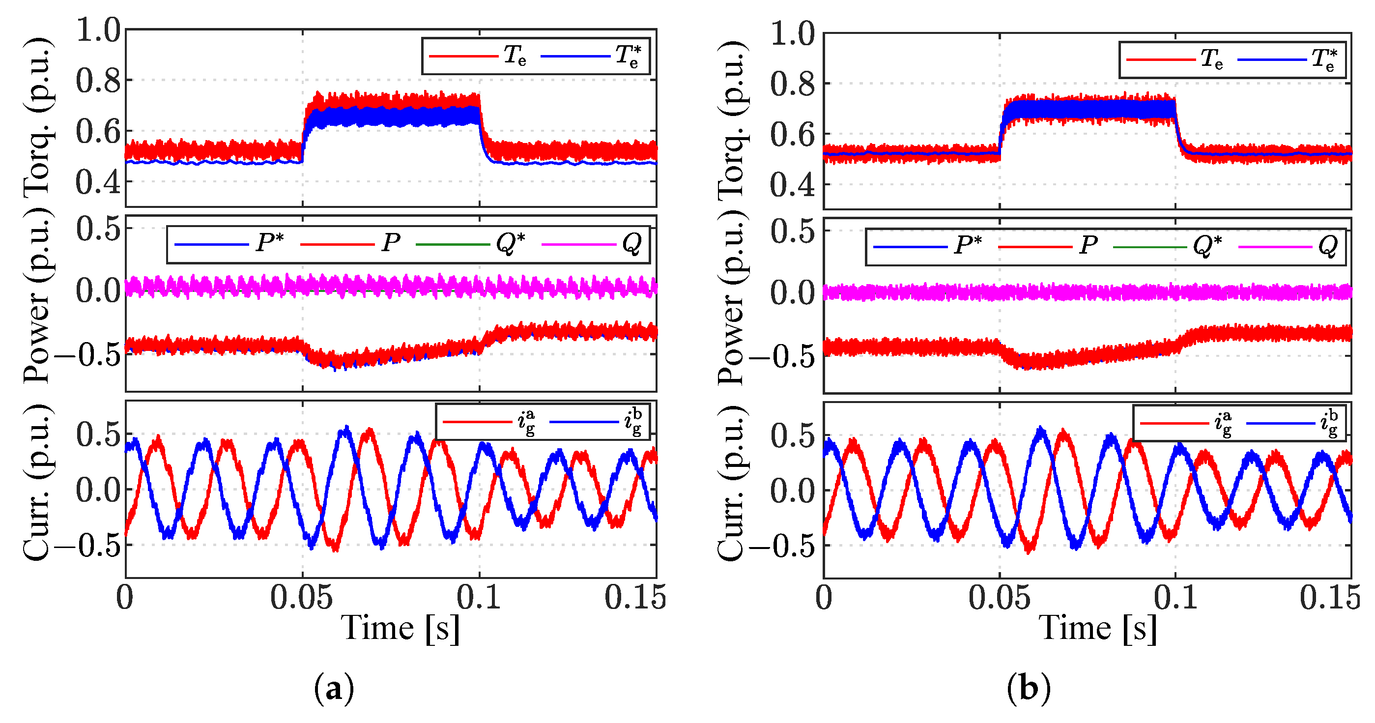
5.1. Overall Validation of the Proposed Method

The test at various operating points is conducted in order to confirm the effectiveness of the system’s overall control. Depending on the wind speed, an optimal torque reference T e * or speed reference ω m * is determined by a proper “maximum power point tracking” (MPPT) control. While the reference generation techniques are not the central focus of this work, for simplicity, the test scenario is designed as follows: the “MPPT speed reference” ω m * has multiple changes, with a particularly steep slope to test the roughest conditions; the DC-link voltage reference V d * remains 600 V during the whole process; reactive power reference is set at 0 var to achieve unity power factor control.
Figure 3a shows the overall performances of the proposed method, and the zoomed performances are given in Figure 3b. The waveforms show that the proposed MIPC achieved good steady and transient state performances globally. The smooth and good tracking of speed, current, and power for both sides of the back-to-back converter is obtained, and the DC-link voltage remains stable in both the steady state and the transient state.

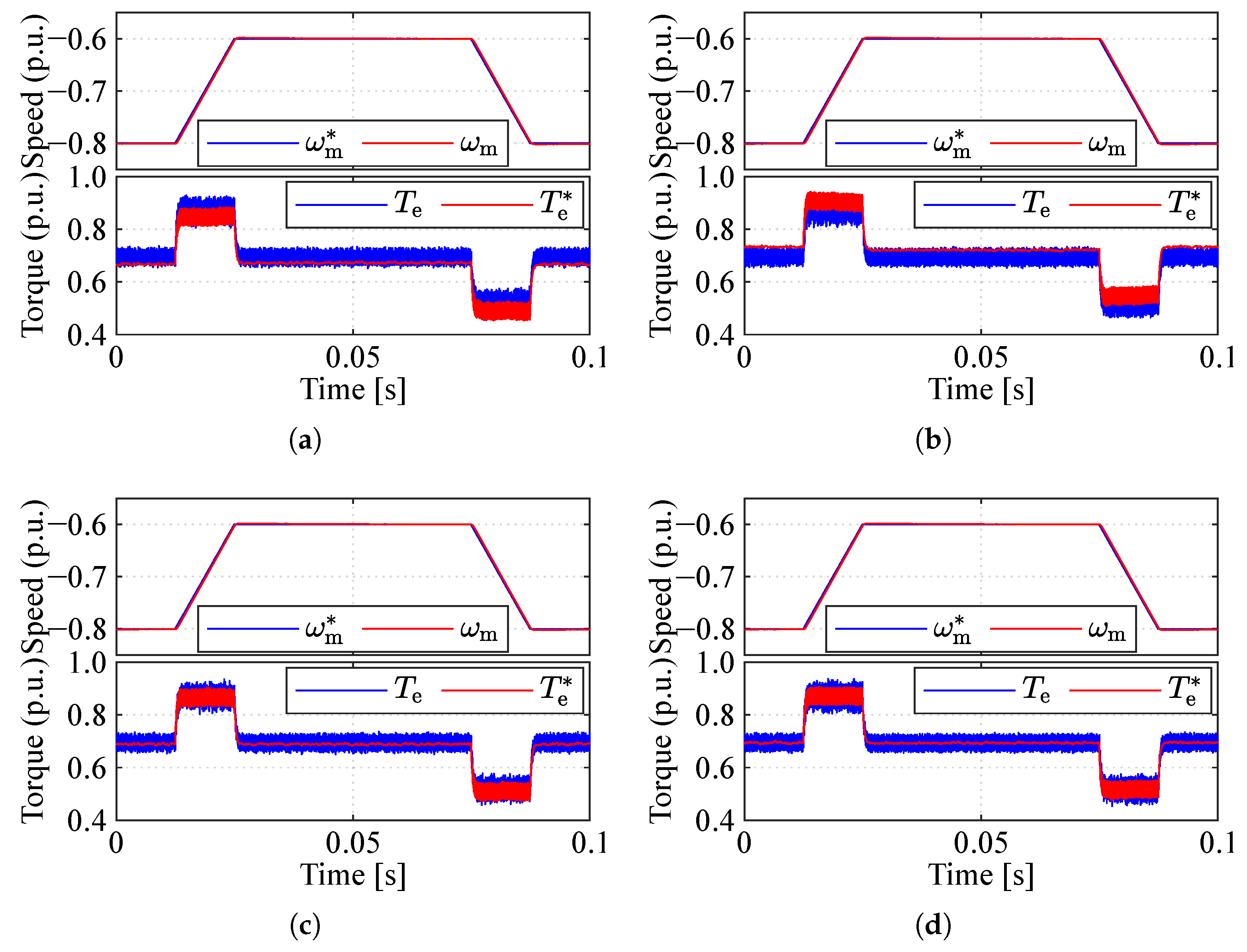
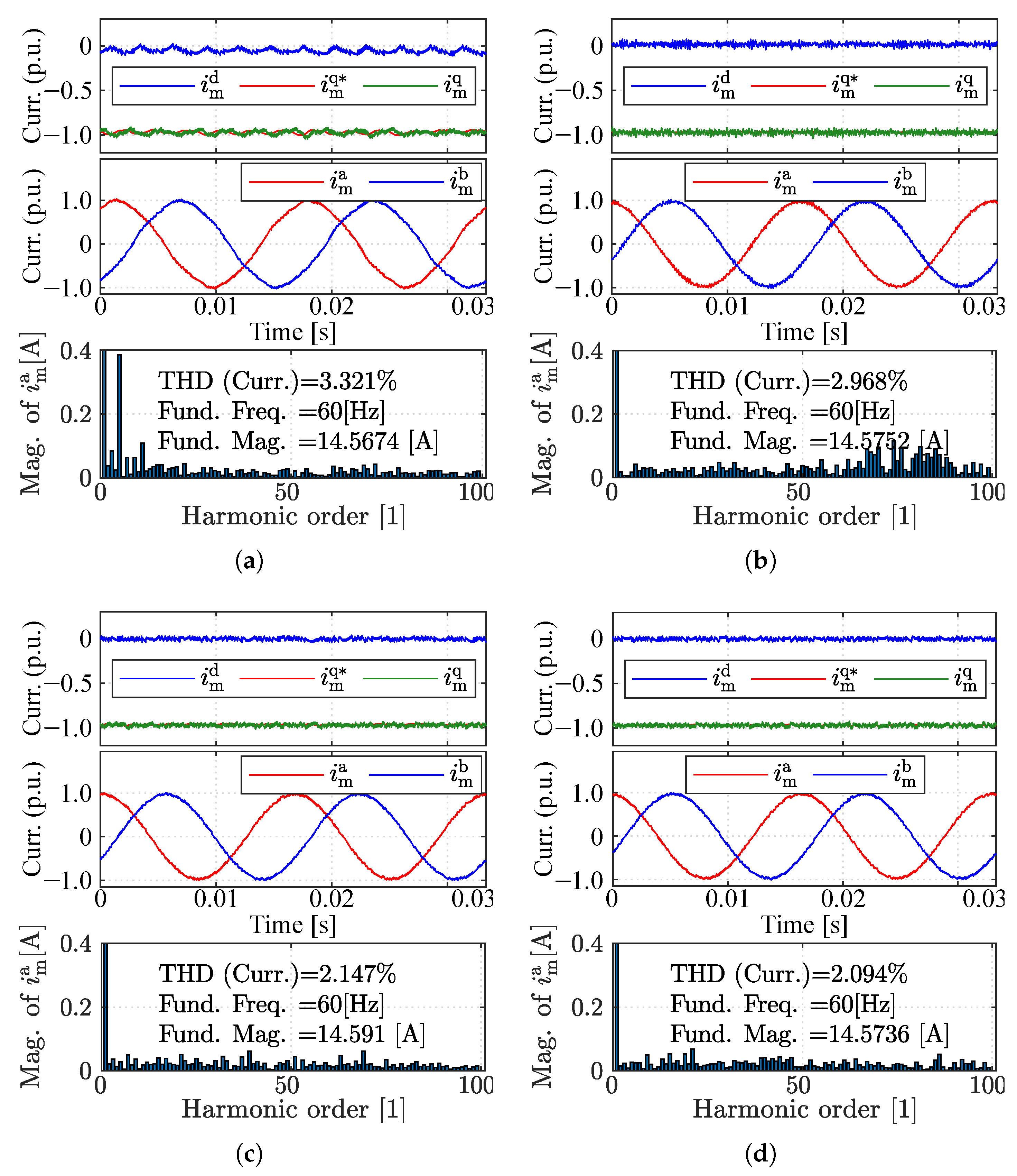
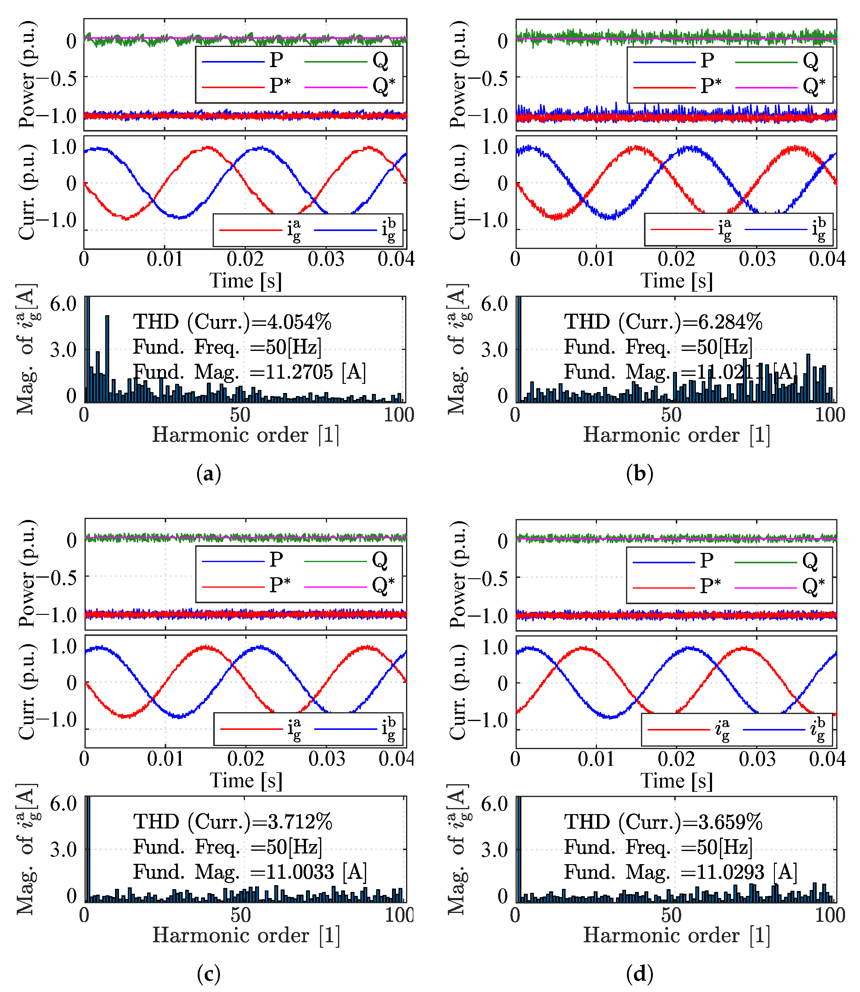
5.2. Robustness Comparison

Under various parameter mismatch conditions, the control performances of the proposed MIPC and the classical DPMC method are compared in this section. For a fair evaluation, the same test scenarios were created for both control methods in each condition.
In the first test, the permanent-magnet flux linkage in the controller is varied to 50% and 200% of the actual value ( ψ pm ) to investigate the influence of flux variation. As can be seen from Figure 4, flux mismatch will mainly lead to torque tracking bias. For 50% flux error, the torque is 4.5% larger than the reference. For 200% flux error, the torque is 5.8% smaller than the reference. This phenomenon is in accordance with the analytical analysis presented in [16].The control performance of the proposed MIPC is unaffected for the permanent-magnet flux linkage variations, which is in line with the principle that ψ pm is not introduced throughout the control process of this method.
In the controller of the classical DMPC solution, we set the inductance of the filter and PMSG stator to vary from 50% to 200% compared to the actual value in the wind turbine system plant. The results are shown in Figure 5 (generator side) and Figure 6 (grid side). Obviously, inaccurate inductance parameters will cause increased ripples (both dq-axis currents and active and reactive power) and enlarge current THDs. The stator current THD increased from 2.14% with the nominal parameter to 3.321% with 0.5 L s and to 2.968% with 2 L s . The grid-side performances in terms of current THD both exceed 4% with 0.5 L g and with 2 L g , which represents deterioration in power quality compared to the performance with the nominal parameter (3.712%). The control performances under various parameters’ mismatches are all collected in Table 2. The results are in accordance with the theoretical analysis, i.e., the controller will derive the wrong prediction of the system utilizing mismatched parameters relating to the selection of the non-optimal control vectors. This will seriously affect the control performance. The control performance of the proposed MIPC is unaffected for all parameter variations, which is in line with the principle that no parameters are introduced throughout the control process of this method. In this section, we verify the good robustness of the proposed model-independent approach compared to the classical DMPC.
In addition, the Classical DMPC and proposed MIPC under several simultaneous parameter mismatches are also tested. In the DMPC controller, the permanent-magnet flux linkage and the inductance of the PMSG stator are set to 50% as the actual value, while the filter inductance is set to 200% as the actual value. The performances are given in Figure 7. The tracking of torque and power as well as the current distortion show that the control performance of the proposed MIPC does not deteriorate even in the face of multiple mismatch at the same time and still shows higher robustness than the classical DMPC.

5.3. Current/Power Update Mechanism Comparison between the Proposed and the Classical MIPC

System prediction is the key to the control performance of the predictive controller. In the proposed MIPC, the fast and accurate state variable variation estimation contributes to the accurate prediction of the system (see Figure 8). The proposed MIPC updates current and power variation for all possible voltage vectors during one control interval by means of the measured k − 1 and k − 2 instant values. Fast variable variation update frequency can be assured; see Figure 9a. The classical MIPC scheme in [24] updates the current and power variation only once for one voltage vector during the whole control interval. Stagnant current and power variation appear when one voltage vector is not applied for long consecutive control intervals; see Figure 9b. Comparing the sampled values of the system with the predicted values calculated using the LUTs in Figure 8, the two overlap, indicating that the proposed model-independent predictive control accurately predicts the trajectory of the system at future moments, which guarantees the control performance.

6. Conclusions

Constrained by its complete dependence on the model, conventional direct model predictive control easily exhibits deterioration in control performance when the model parameters are mismatched. State-of-the-art model-independent predictive control (MIPC) introduces historical operation data in the prediction of future statuses. Nevertheless, it suffers from low look-up table (LUT) update frequency, unsteady state variable changing rate, and extensive computational burden. This work proposed an improved MIPC with a new look-up table update method that only introduces the information from the former two instants to estimate all needed variations in the same period. Compared with the traditional finite-set model predictive control and the existing MIPC, the proposed solution achieves robustness to unmeasurable and time-varying parameters without sacrificing control performance. The proposed method can be applied to other power converter topologies with minor modifications. Future work will focus on addressing measurement robustness and extending the proposed methods to multilevel power conversion systems.

Author Contributions

Conceptualization, Z.Z. and X.L.; methodology, Y.Z. and X.L.; software, X.L. and H.L.; validation, H.L. and Y.Z.; formal analysis, Y.Z.; investigation, Y.Z. and X.L.; resources, Y.Z.; data curation, Y.Z.; writing—original draft preparation, Y.Z. and X.L.; writing—review and editing, Y.Z. and Z.Z.; visualization, Y.Z. and X.L.; supervision, Z.Z.; project administration, Z.Z.; funding acquisition, Z.Z. All authors have read and agreed to the published version of the manuscript.

Funding

This research was funded by National Key R & D Program of China under 2022YFB4201700, and in part by the General Program of National Natural Science Foundation of China under Grants 51977124, 52007107, and 52277191.

Data Availability Statement

Data is available upon reasonable request to the corresponding author.

Conflicts of Interest

The authors declare no conflict of interest.

References

  1. Nadeem, M.; Zheng, X.; Tai, N.; Gul, M.; Tahir, S. Analysis of Propagation Delay for Multi-Terminal High Voltage Direct Current Networks Interconnecting the Large-Scale Off-Shore Renewable Energy. Energies 2018, 11, 2115. [Google Scholar] [CrossRef] [Green Version]
  2. Sun, Y.; Zhang, Z.; Zhang, Y.; Li, Y.; Li, Z. A Time-Domain Virtual-Flux Based Predictive Control of Modular Multilevel Converters for Offshore Wind Energy Integration. IEEE Trans. Energy Convers. 2021, 37, 1803–1814. [Google Scholar] [CrossRef]
  3. Steffen, J.; Lengsfeld, S.; Jung, M.; Ponick, B.; Herranz Gracia, M.; Spagnolo, A.; Klöpzig, M.; Schleicher, K.; Schäfer, K. Design of a Medium Voltage Generator with DC-Cascade for High Power Wind Energy Conversion Systems. Energies 2021, 14, 3106. [Google Scholar] [CrossRef]
  4. Blaabjerg, F.; Ma, K. Future on Power Electronics for Wind Turbine Systems. IEEE J. Emerg. Sel. Top. Power Electron. 2013, 1, 139–152. [Google Scholar] [CrossRef]
  5. Liserre, M.; Cardenas, R.; Molinas, M.; Rodriguez, J. Overview of Multi-MW Wind Turbines and Wind Parks. IEEE Trans. Ind. Electron. 2011, 58, 1081–1095. [Google Scholar] [CrossRef]
  6. Zhang, Z.; Li, Z.; Kazmierkowski, M.P.; Rodriguez, J.; Kennel, R. Robust Predictive Control of Three-Level NPC Back-to-Back Power Converter PMSG Wind Turbine Systems with Revised Predictions. IEEE Trans. Power Electron. 2018, 33, 9588–9598. [Google Scholar] [CrossRef]
  7. Singh, V.; Tripathi, R.; Hanamoto, T. HIL Co-Simulation of Finite Set-Model Predictive Control Using FPGA for a Three-Phase VSI System. Energies 2018, 11, 909. [Google Scholar] [CrossRef] [Green Version]
  8. Zhang, J.; Sun, T.; Wang, F.; Rodriguez, J.; Kennel, R. A Computationally Efficient Quasi-Centralized DMPC for Back-to-Back Converter PMSG Wind Turbine Systems without DC-Link Tracking Errors. IEEE Trans. Ind. Electron 2016, 63, 6160–6171. [Google Scholar] [CrossRef]
  9. Zhang, Z.; Wang, F.; Wang, J.; Rodriguez, J.; Kennel, R. Nonlinear Direct Control for Three-Level NPC Back-to-Back Converter PMSG Wind Turbine Systems: Experimental Assessment With FPGA. IEEE Trans. Ind. Inform. 2017, 13, 1172–1183. [Google Scholar] [CrossRef]
  10. Zhang, Z.; Fang, H.; Gao, F.; Rodriguez, J.; Kennel, R. Multiple-Vector Model Predictive Power Control for Grid-Tied Wind Turbine System with Enhanced Steady-State Control Performance. IEEE Trans. Ind. Electron. 2017, 64, 6287–6298. [Google Scholar] [CrossRef]
  11. Lyu, Z.; Wu, X.; Gao, J.; Tan, G. An Improved Finite-Control-Set Model Predictive Current Control for IPMSM under Model Parameter Mismatches. Energies 2021, 14, 6342. [Google Scholar] [CrossRef]
  12. Xu, Y.; Ding, X.; Wang, J.; Wang, C. Robust Three-vector-based Low-complexity Model Predictive Current Control with Supertwisting-algorithm-based Second-order Sliding-mode Observer for Permanent Magnet Synchronous Motor. IET Power Electron. 2019, 12, 2895–2903. [Google Scholar] [CrossRef]
  13. Zhang, Y.; Wu, Z.; Yan, Q.; Huang, N.; Du, G. An Improved Model-Free Current Predictive Control of Permanent Magnet Synchronous Motor Based on High-Gain Disturbance Observer. Energies 2022, 16, 141. [Google Scholar] [CrossRef]
  14. Gao, P.; Zhang, G.; Lv, X. Model-Free Control Using Improved Smoothing Extended State Observer and Super-Twisting Nonlinear Sliding Mode Control for PMSM Drives. Energies 2021, 14, 922. [Google Scholar] [CrossRef]
  15. Abdelrahem, M.; Hackl, C.M.; Zhang, Z.; Kennel, R. Robust Predictive Control for Direct-Driven Surface-Mounted Permanent-Magnet Synchronous Generators without Mechanical Sensors. IEEE Trans. Energy Convers. 2018, 33, 179–189. [Google Scholar] [CrossRef]
  16. Zhang, X.; Zhang, L.; Zhang, Y. Model Predictive Current Control for PMSM Drives with Parameter Robustness Improvement. IEEE Trans. Power Electron. 2019, 34, 1645–1657. [Google Scholar] [CrossRef]
  17. Zhang, X.; Cheng, Y.; Zhao, Z.; He, Y. Robust Model Predictive Direct Speed Control for SPMSM Drives Based on Full Parameter Disturbances and Load Observer. IEEE Trans. Power Electron. 2020, 35, 8361–8373. [Google Scholar] [CrossRef]
  18. Hu, M.; Yang, F.; Liu, Y.; Wu, L. Finite Control Set Model-Free Predictive Current Control of a Permanent Magnet Synchronous Motor. Energies 2022, 15, 1045. [Google Scholar] [CrossRef]
  19. Siami, M.; Khaburi, D.A.; Abbaszadeh, A.; Rodriguez, J. Robustness Improvement of Predictive Current Control Using Prediction Error Correction for Permanent-Magnet Synchronous Machines. IEEE Trans. Ind. Electron. 2016, 63, 3458–3466. [Google Scholar] [CrossRef]
  20. Siami, M.; Khaburi, D.A.; Rodriguez, J. Torque Ripple Reduction of Predictive Torque Control for PMSM Drives With Parameter Mismatch. IEEE Trans. Power Electron. 2017, 32, 7160–7168. [Google Scholar] [CrossRef]
  21. Liu, X.; Zhou, L.; Wang, J.; Gao, X.; Li, Z.; Zhang, Z. Robust Predictive Current Control of Permanent-Magnet Synchronous Motors with Newly Designed Cost Function. IEEE Trans. Power Electron. 2020, 35, 10778–10788. [Google Scholar] [CrossRef]
  22. Sabzevari, S.; Heydari, R.; Mohiti, M.; Savaghebi, M.; Rodriguez, J. Model-Free Neural Network-Based Predictive Control for Robust Operation of Power Converters. Energies 2021, 14, 2325. [Google Scholar] [CrossRef]
  23. Lin, C.-K.; Liu, T.-H.; Yu, J.; Fu, L.-C.; Hsiao, C.-F. Model-Free Predictive Current Control for Interior Permanent-Magnet Synchronous Motor Drives Based on Current Difference Detection Technique. IEEE Trans. Ind. Electron. 2014, 61, 667–681. [Google Scholar] [CrossRef]
  24. Lin, C.-K.; Yu, J.; Lai, Y.-S.; Yu, H.-C. Improved Model-Free Predictive Current Control for Synchronous Reluctance Motor Drives. IEEE Trans. Ind. Electron. 2016, 63, 3942–3953. [Google Scholar] [CrossRef]
  25. Carlet, P.G.; Tinazzi, F.; Bolognani, S.; Zigliotto, M. An Effective Model-Free Predictive Current Control for Synchronous Reluctance Motor Drives. IEEE Trans. Ind. Appl. 2019, 55, 3781–3790. [Google Scholar] [CrossRef] [Green Version]
  26. Zhou, D.; Jiang, C.; Quan, Z.; Li, Y. Vector Shifted Model Predictive Power Control of Three-Level Neutral-Point-Clamped Rectifiers. IEEE Trans. Ind. Electron. 2020, 67, 7157–7166. [Google Scholar] [CrossRef]
  27. Zhang, Z.B. On Control of Grid-Tied Back-to-Back Power Converters and Pmsg Wind Turbine Systems. Ph.D. Dissertation, Technical University of Munich, Munich, Germany, 2016. [Google Scholar]
  28. Zhang, Z.; Wang, F.; Sun, T.; Rodriguez, J.; Kennel, R. FPGA-Based Experimental Investigation of a Quasi-Centralized Model Predictive Control for Back-to-Back Converters. IEEE Trans. Power Electron. 2016, 31, 662–674. [Google Scholar] [CrossRef]
  29. Cortes, P.; Rodriguez, J.; Silva, C.; Flores, A. Delay Compensation in Model Predictive Current Control of a Three-Phase Inverter. IEEE Trans. Ind. Electron. 2012, 59, 1323–1325. [Google Scholar] [CrossRef]
  30. Wang, F.; Zhang, Z.; Mei, X.; Rodríguez, J.; Kennel, R. Advanced Control Strategies of Induction Machine: Field Oriented Control, Direct Torque Control and Model Predictive Control. Energies 2018, 11, 120. [Google Scholar] [CrossRef] [Green Version]
Figure 1. Simplified electrical circuit of a two-level back-to-back power converter-based PMSG wind turbine system with equivalent RL-filter.
Energies 16 03764 g001
Figure 2. Control scheme of the proposed model-independent solution for back-to-back power converter based PMSG wind turbine system.
Energies 16 03764 g002
Figure 3. Performance of the proposed MIPC method. (a) Overall control performance. (b) Zoomed control performance. From top to bottom are the PMSG mechanical speed, stator dq-axis currents, DC-link voltage, grid-side currents, active and reactive power, and their references, respectively. The speed base is 125 r/min. The current base is 15 A.
Energies 16 03764 g003
Figure 4. Performances under permanent-magnet flux linkage variations: (a) Classical DMPC (50% ψ pm ); (b) Classical DMPC (200% ψ pm ); (c) Classical DMPC (100% ψ pm ); (d) Proposed MIPC. For all sub-figures, from top to bottom are the generator speed (base value 125 [rad/s]) and the generator torque (base value 29 [ N · m ]), respectively.
Energies 16 03764 g004
Figure 5. Generator side: (a) Classical DMPC (50% L s ); (b) Classical DMPC (200% L s ); (c) Classical DMPC (100% L s ); (d) Proposed MIPC. For all sub-figures, from top to bottom are the dq-axis stator current and their references (base value 15 [A]), phase currents, and the current spectrum, respectively.
Energies 16 03764 g005
Figure 6. Grid side: (a) Classical DMPC (50% L g ); (b) Classical DMPC (200% L g ); (c) Classical DMPC (100% L g ); (d) Proposed MIPC. For all sub-figures, from top to bottom are the active and reactive power (base value 3475 [W]) and their references, phase currents, and the current spectrum (base value 15 [A]), respectively.
Energies 16 03764 g006
Figure 7. The control performance in the face of multiple mismatches: (a) Classical DMPC; (b) Proposed MIPC. For all sub-figures, from top to bottom are the generator torque (base value 30 [Nm]), the active and reactive power (base value 3475 [W]) and their references, and the phase currents on the grid side (base value 15 [A]), respectively.
Energies 16 03764 g007
Figure 8. Prediction accuracy of the proposed MIPC. (a) Q-axis stator current and grid power prediction validation. (b) Zoomed comparison between measurement and prediction.
Energies 16 03764 g008
Figure 9. Estimated d-axis current variation and active power variation caused by different voltage vectors using (a) the proposed MIPC and (b) classical MIPC [24]. S x 1 S x 8 denote the available voltage vectors of the machine side ( x = m ) and the grid side ( x = g ), respectively.
Energies 16 03764 g009
Table 1. System configuration.
ParameterValueParameterValue
DC-link Voltage V d ( V ) 600DC Capacitance C ( F ) 1100 × 10 6
PMSG Inductance L s d = L s q ( H ) 19.43 × 10 3 PMSG Resistance R s ( Ω ) 0.14
Nominal Torque T e n ( N · m )29Nominal Power P n  (kVA) 3.475
PM Flux ψ p m ( Wb ) 0.43PMSG Pole Pairs N p (-)3
PMSG Inertia J   ( kg · m 2 ) 0.01Grid Voltage e g abc (V) 210 / 2
Grid Frequency ω g (rad/s)100 π Filter Resistance R g ( Ω ) 1.56 × 10 3
Filter Inductance L g (H) 16 × 10 3 Sampling Time T s ( μ s)50
Table 2. Comparative test data of classical DMPC and proposed MIPC.
Control MethodMaximum Torque ErrorGenerator Current THDGrid Current THD
Classical DMPC4.50% (50%  ψ pm )3.32% (50%  L s )4.05% (50%  L g )
5.80% (200%  ψ pm )2.97% (200%  L s )6.28% (200%  L g )
0.73% (100%  ψ pm )2.15% (100%  L s )3.71% (100%  L g )
Proposed MIPC0.75%2.09%3.66%
Disclaimer/Publisher’s Note: The statements, opinions and data contained in all publications are solely those of the individual author(s) and contributor(s) and not of MDPI and/or the editor(s). MDPI and/or the editor(s) disclaim responsibility for any injury to people or property resulting from any ideas, methods, instructions or products referred to in the content.

