Quasi-Resonant Single-Switch High-Voltage-Gain DC-DC Converter with Coupled Inductor and Voltage Multiplier Cell
Abstract
1. Introduction
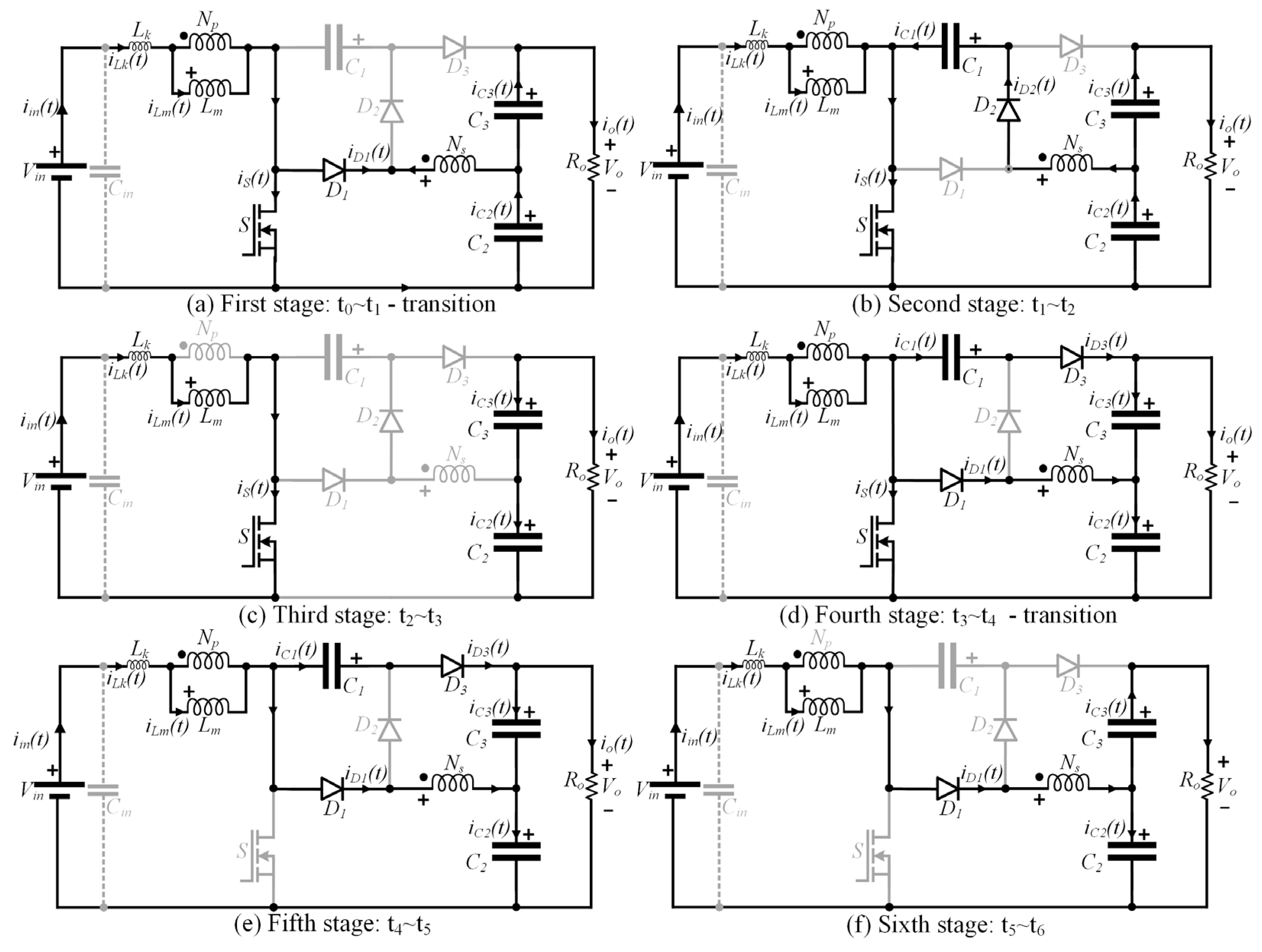
2. Principle of Operation in Steady State
- All elements are considered ideal, except for the leakage inductance of the coupled inductor;
- The voltage on the capacitors and the magnetizing current are assumed to be ripple free;
- The analysis is carried out within one period of the switching frequency fs.
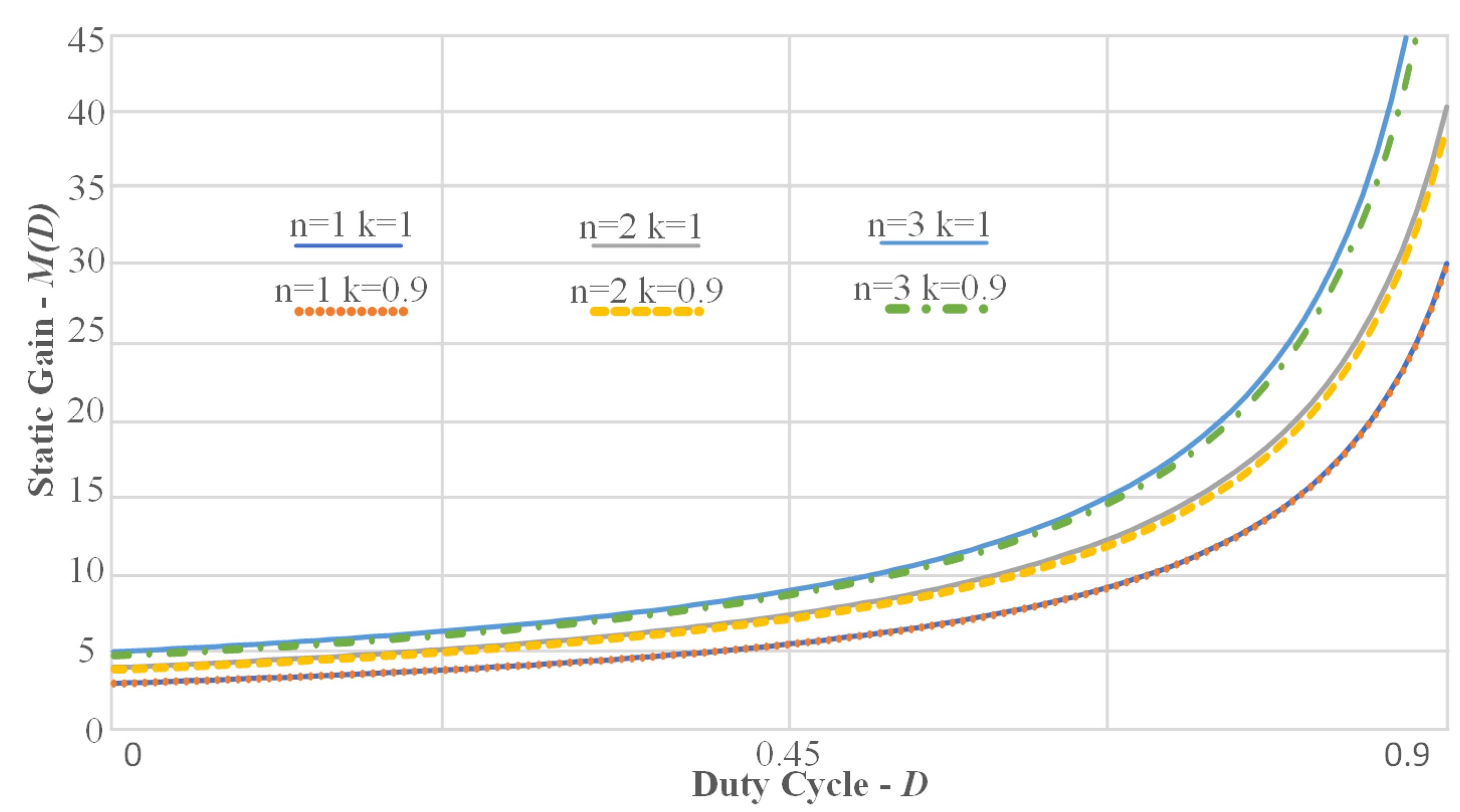
3. Mathematical Model
3.1. Steady-State Analysis
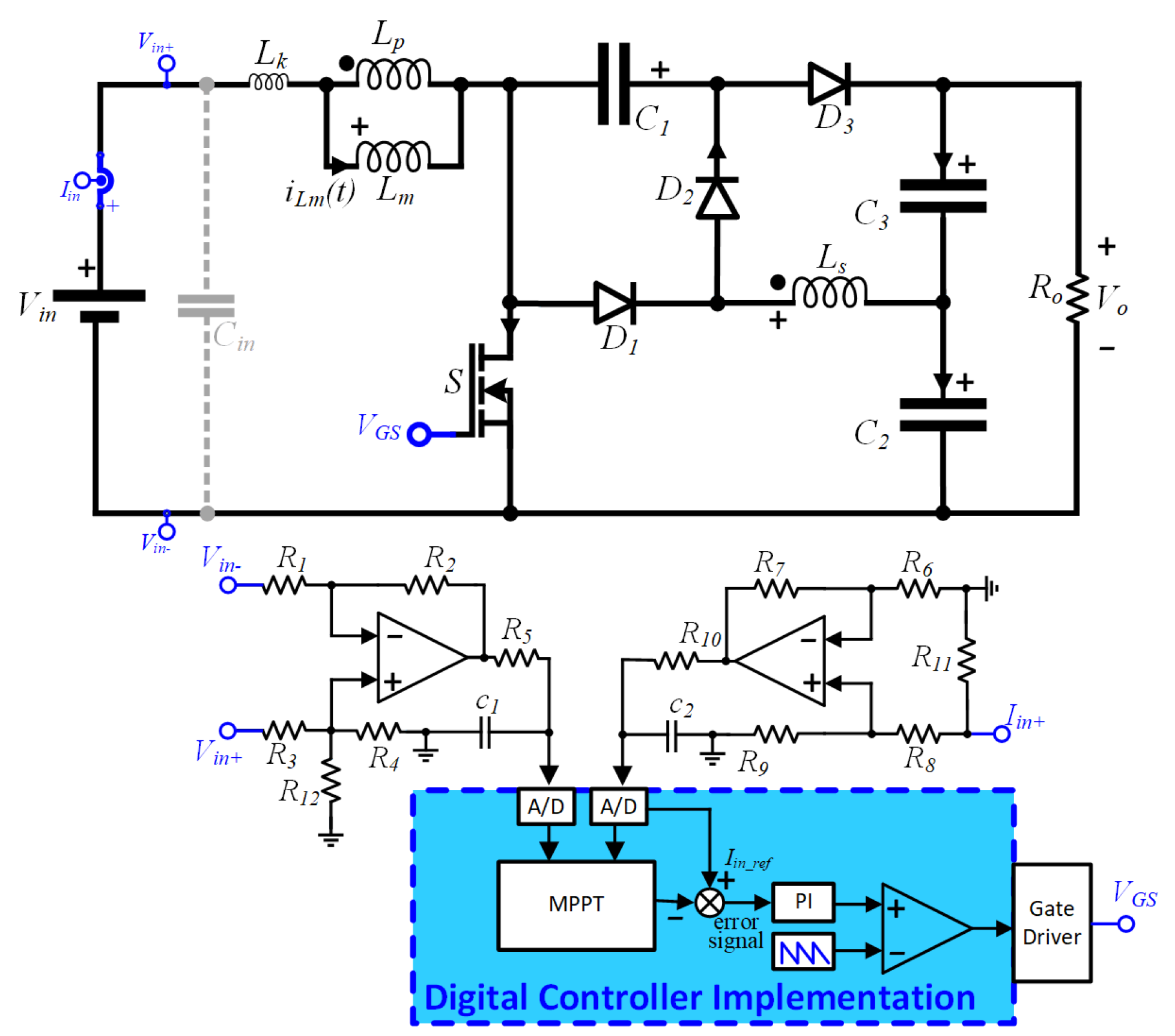
3.2. Control Strategy
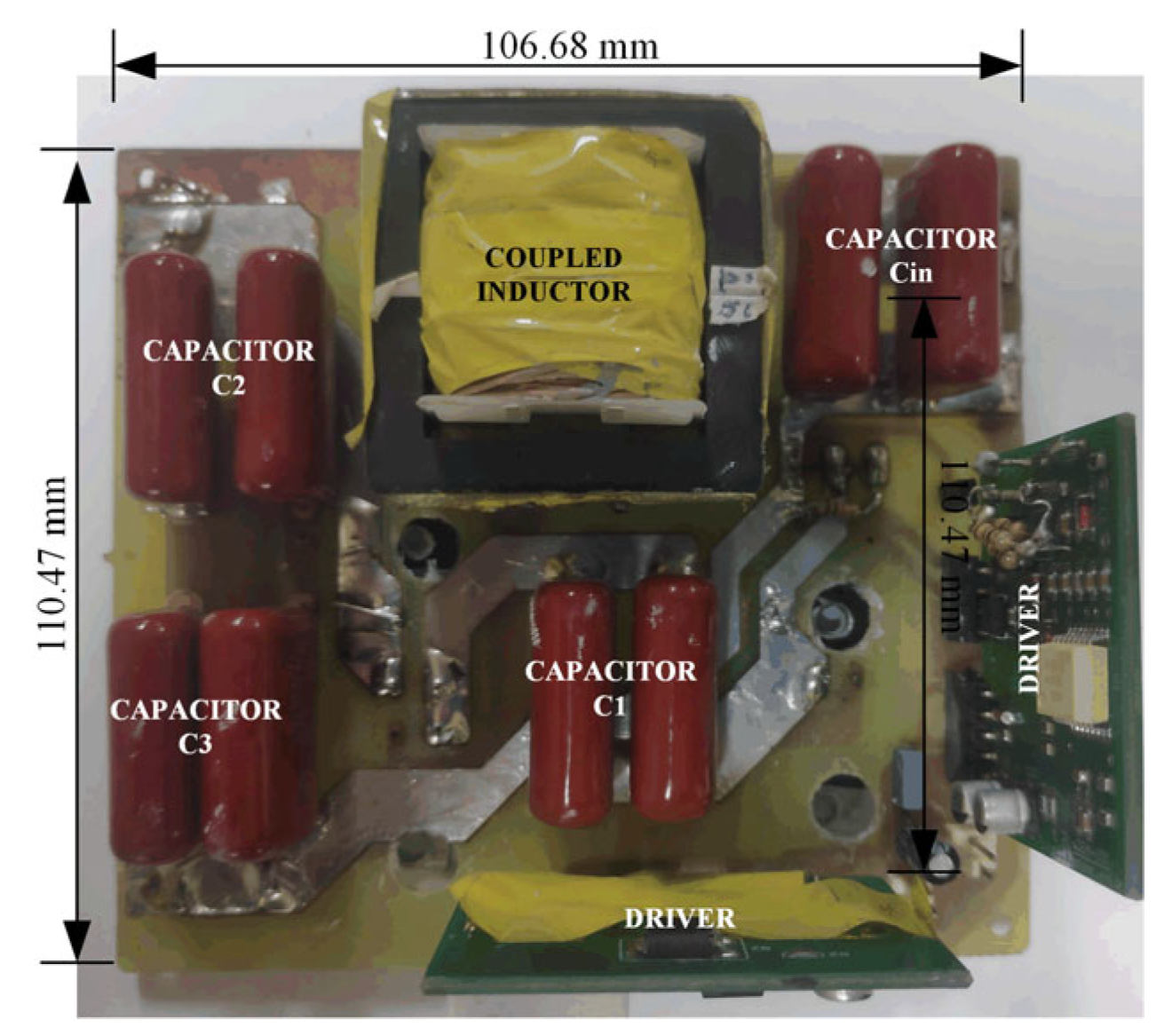
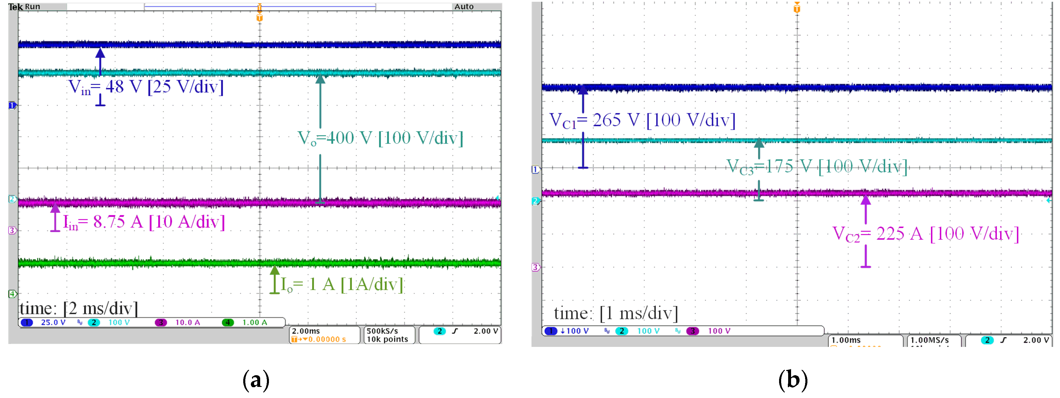
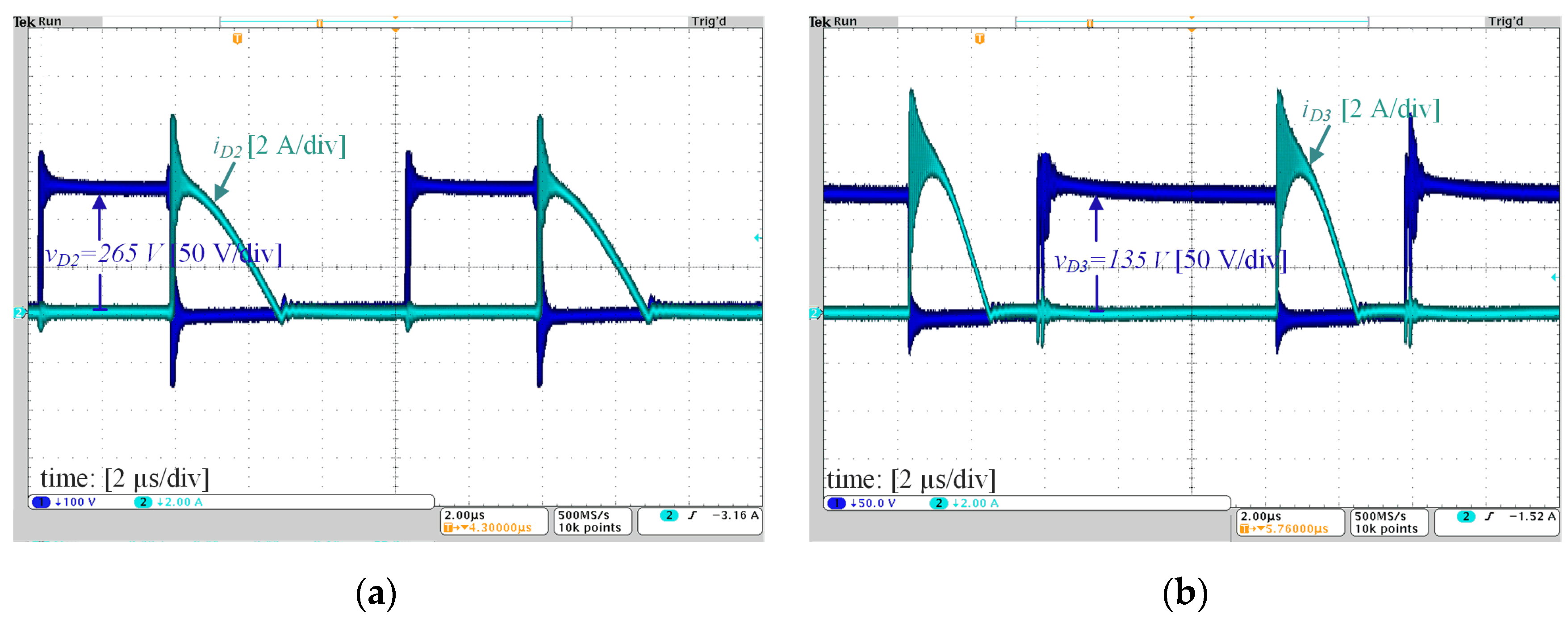
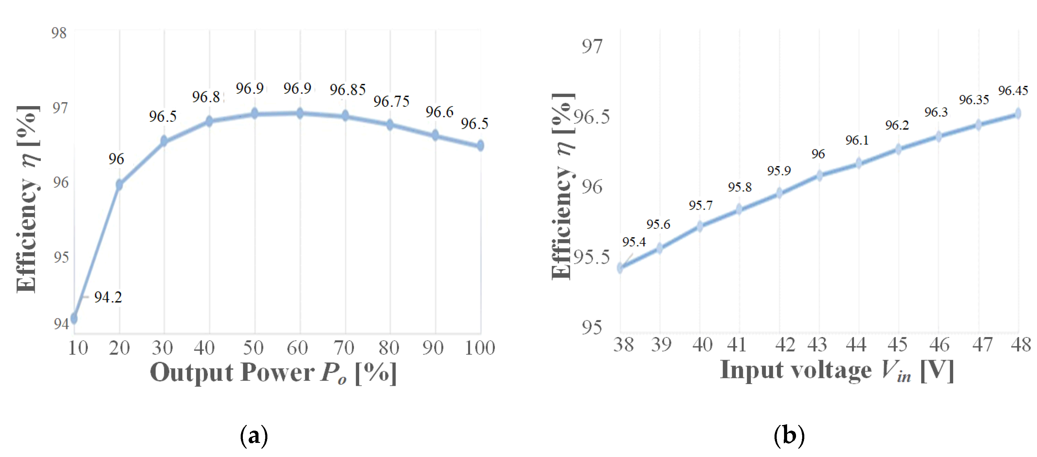
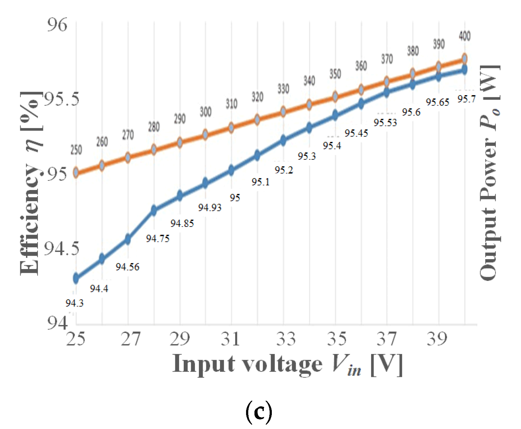
4. Experimental Results
Comparative Analysis
5. Conclusions
Author Contributions
Funding
Data Availability Statement
Conflicts of Interest
Nomenclature
| Abbreviations | |
| AC | Alternate Current |
| DC | Direct Current |
| FC | Fuel Cell |
| MPPT | Maximum Power Point Tracking |
| PI | Proportional–Integral |
| PV | Photovoltaic |
| VMC | Voltage Multiplier Cell |
| ZCS | Zero Current Switching |
| Symbols | |
| ∆ILm | Current ripple on Lm |
| ∆ti | Interval of the i-th operating stage |
| ∆VC1, ∆VC2, ∆VC3 | Voltage ripple on C1, C2 and C3 |
| λ | Inductance factor 1 |
| ωo | Resonant angular frequency |
| A | Simplifying term |
| Ceq1 | Equivalent capacitance |
| D | Duty cycle |
| fo | Resonant frequency |
| fs | Switching frequency |
| iC1, iC2, iC3 | Instantaneous current on C1, C2 and C3 |
| iin | Instantaneous input current |
| iLk | Instantaneous current on Lk |
| ILk(s) | Laplace transform of iLk |
| ILk1 | Current on Lk at t = t1 |
| ILk2 | Current on Lk at t = t4 |
| ILm | Average value of the current on Lm |
| Io | Average value of the output current |
| k | Inductance factor 2 |
| M | Voltage gain |
| MC1, MC2, MC3 | Partial voltage gains on C1, C2 and C3 |
| n | Number of turns ratio |
| RDSon | On-resistance of the MOSFET |
| Ts | Switching period |
| vC1, vC2, vC3 | Instantaneous voltage on C1, C2 and C3 |
| VD1, VD2, VD3 | Maximum voltage stress on diodes D1, D2 and D3 |
| Vin | Input voltage |
| VGS | Gate-to-source voltage on the MOSFET |
| vLk | Instantaneous voltage on Lk |
| Vo | Output voltage |
| VS | Maximum voltage stress on switch S |
References
- Shubbak, M.H. Advances in solar photovoltaics: Technology review and patent trends. Renew. Sustain. Energy Rev. 2019, 115, 109383. [Google Scholar] [CrossRef]
- Li, Z.; Ma, T.; Yang, H.; Lu, L.; Wang, R. Transparent and colored solar photovoltaics for building integration. Solar RRL 2021, 5, 2000614. [Google Scholar] [CrossRef]
- Premkumar, M.; Subramaniam, U.; Haes Alhelou, H.; Siano, P. Design and Development of Non-Isolated Modified SEPIC DC-DC Converter Topology for High-Step-Up Applications: Investigation and Hardware Implementation. Energies 2020, 13, 3960. [Google Scholar] [CrossRef]
- Zheng, Y.; Smedley, K.M. Analysis and design of a single-switch high step-up coupled-inductor boost converter. IEEE Trans. Power Electron. 2020, 35, 535–545. [Google Scholar] [CrossRef]
- Hass, E.S.; Nascimento, C.B. A simple self-clamped high step-up DC-DC converter employing coupled inductor. Braz. Power Electron. J. 2019, 24, 204–213. [Google Scholar]
- Rosas, I.P.; Agostini, E.; Nascimento, C.B. Single-switch high-step-up DC-DC converter employing coupled inductor and voltage multiplier cell. IEEE Access 2022, 10, 82626–82635. [Google Scholar] [CrossRef]
- Wu, Y.-E.; Wu, Y.-L. Design and Implementation of a High Efficiency, Low Component Voltage Stress, Single-Switch High Step-Up Voltage Converter for Vehicular Green Energy Systems. Energies 2016, 9, 772. [Google Scholar] [CrossRef]
- Rahimi, T.; Islam, M.R.; Gholizadeh, H.; Mahdizadeh, S.; Afjei, E. Design and Implementation of a High Step-Up DC-DC Converter Based on the Conventional Boost and Buck-Boost Converters with High Value of the Efficiency Suitable for Renewable Application. Sustainability 2021, 13, 10699. [Google Scholar] [CrossRef]
- Pereira, A.V.C.; Cavalcanti, M.C.; Azevedo, G.M.; Bradaschia, F.; Neto, R.C.; Santos de Carvalho, M.R. A Novel Single-Switch High Step-Up DC–DC Converter with Three-Winding Coupled Inductor. Energies 2021, 14, 6288. [Google Scholar] [CrossRef]
- Li, W.; He, X. Review of nonisolated high-step-up DC/DC converters in photovoltaic grid-connected applications. IEEE Trans. Ind. Electron. 2011, 58, 1239–1250. [Google Scholar] [CrossRef]
- Liu, H.; Hu, H.; Wu, H.; Xing, Y.; Batarseh, I. Overview of high-step-up coupled-inductor boost converters. IEEE J. Emerg. Sel. Top. Power Electron. 2016, 4, 689–704. [Google Scholar] [CrossRef]
- Forouzesh, M.; Siwakoti, Y.P.; Gorji, S.A.; Blaabjerg, F.; Lehman, B. Step-up DC–DC converters: A comprehensive review of voltage-boosting techniques, topologies, and applications. IEEE Trans. Power Electron. 2017, 32, 9143–9178. [Google Scholar] [CrossRef]
- Tseng, K.C.; Liang, T.J. Novel high-efficiency step-up converter. IEE Proc. Electr. Power Appl. 2004, 151, 182–190. [Google Scholar] [CrossRef]
- Baek, J.-W.; Ryoo, M.-H.; Kim, T.-J.; Yoo, D.-W.; Kim, J.-S. High Boost Converter Using Voltage Multiplier. In Proceedings of the 31st Annual Conference of IEEE Industrial Electronics Society (IECON), Raleigh, NC, USA, 6–10 November 2005. [Google Scholar]
- Hsieh, Y.-P.; Chen, J.-F.; Liang, T.-J.; Yang, L.-S. A novel high step-up DC–DC converter for a microgrid system. IEEE Trans. Power Electron. 2011, 26, 1127–1136. [Google Scholar] [CrossRef]
- Wai, R.-J.; Duan, R.-Y. High step-up converter with coupled inductor. IEEE Trans. Power Electron. 2005, 20, 1025–1035. [Google Scholar] [CrossRef]
- Hu, X.; Gong, C. A High Voltage Gain DC–DC Converter Integrating Coupled-Inductor and Diode–Capacitor Techniques. IEEE Trans. Power Electron. 2014, 29, 789–800. [Google Scholar]
- Abbasian, S.; Farsijani, M. A single-switch high step-up Zero Current Switching DC-DC converter based on three-winding coupled inductor and voltage multiplier cells with quasi resonant operation. Int. J. Circ. Theory Appl. 2022, 50, 4419–4433. [Google Scholar] [CrossRef]
- Schmitz, L.; Martins, D.C.; Coelho, R.F. Generalized high step-up DC-DC boost-based converter with gain cell. IEEE Trans. Circ. Syst. I Reg. Papers 2017, 64, 480–493. [Google Scholar] [CrossRef]
- Lee, H.-S.; Yun, J.-J. Quasi-resonant voltage doubler with snubber capacitor for boost half-bridge DC–DC converter in photovoltaic micro-inverter. IEEE Trans. Power Electron. 2019, 34, 8377–8388. [Google Scholar] [CrossRef]
- Hasanpour, S.; Baghramian, A.; Mojallali, H. A modified SEPIC-based high step-up DC–DC converter with quasi-resonant operation for renewable energy applications. IEEE Trans. Ind. Electron. 2019, 66, 3539–3549. [Google Scholar] [CrossRef]
- Roshandel, E.; Mahmoudi, A.; Kahourzade, S.; Emami, H.D. DC-DC High-Step-Up Quasi-Resonant Converter to Drive Acoustic Transmitters. Energies 2022, 15, 5745. [Google Scholar] [CrossRef]



| Symbol | Description | Value |
|---|---|---|
| Vin | Input voltage | 48 V |
| fs | Switching frequency | 100 kHz |
| Po | Output power | 400 W |
| Vo | Output voltage | 400 V |
| n | Number of turns ratio | 1 |
| k | Inductance factor | 95% |
| Lk | Leakage inductance | 2 µH |
| fo | Resonant frequency | 1.6·fs |
| ∆ILm | Current ripple on Lm | 45% of Iin |
| ∆VC3 | Voltage ripple on C3 | 1% of VC3 |
| Parameter | Value |
|---|---|
| D | 0.644 |
| Lm | 80 µH, E42/15, Np = Ns = 16 |
| C1 | 3 µF/400 V |
| C2 | 3 µF/400 V |
| C3 | 3 µF/400 V |
| D1, D2 and D3 | MUR 840 |
| S | IRFP4668PBF |
| Reference | Voltage Gain (Vo/Vin) | Voltage Stress on the Switch | Voltage Stress on the Diodes | Number of Capacitors | Number of Diodes | Efficiency η | ||
|---|---|---|---|---|---|---|---|---|
| VD1 | VD2 | VD3 | ||||||
| Proposed | 3 | 3 | 96.5% @400 W, 100 kHz, n = 1 | |||||
| [5] | - | 2 | 2 | 94% @300 W, 100 kHz, n = 3 | ||||
| [6] | 3 | 3 | 96.5% @400 W, 90 kHz, n = 1.72 | |||||
| [13] | Limited by the RCD snubber 1 | Voltage stress on the snubber diode 1 | 3 | 3 | 93% @35 W, 38 kHz, n = 2 | |||
| [14] | 3 | 3 | Not reported, 20 kHz, n = 1 | |||||
| [15] 2 | 4 | 4 | 94.3% @400 W, 50 kHz, n = 1 | |||||
| [16] | 3 | 3 | 94% @300 W, 100 kHz, n = 6 | |||||
| [17] 3 | 4 | 5 | 91.1% @500 W, 40 kHz, n = 1.86 | |||||
Disclaimer/Publisher’s Note: The statements, opinions and data contained in all publications are solely those of the individual author(s) and contributor(s) and not of MDPI and/or the editor(s). MDPI and/or the editor(s) disclaim responsibility for any injury to people or property resulting from any ideas, methods, instructions or products referred to in the content. |
© 2023 by the authors. Licensee MDPI, Basel, Switzerland. This article is an open access article distributed under the terms and conditions of the Creative Commons Attribution (CC BY) license (https://creativecommons.org/licenses/by/4.0/).
Share and Cite
Schiavon, G.L.; Agostini, E., Jr.; Nascimento, C.B. Quasi-Resonant Single-Switch High-Voltage-Gain DC-DC Converter with Coupled Inductor and Voltage Multiplier Cell. Energies 2023, 16, 3874. https://doi.org/10.3390/en16093874
Schiavon GL, Agostini E Jr., Nascimento CB. Quasi-Resonant Single-Switch High-Voltage-Gain DC-DC Converter with Coupled Inductor and Voltage Multiplier Cell. Energies. 2023; 16(9):3874. https://doi.org/10.3390/en16093874
Chicago/Turabian StyleSchiavon, Giordano Luigi, Eloi Agostini, Jr., and Claudinor Bitencourt Nascimento. 2023. "Quasi-Resonant Single-Switch High-Voltage-Gain DC-DC Converter with Coupled Inductor and Voltage Multiplier Cell" Energies 16, no. 9: 3874. https://doi.org/10.3390/en16093874
APA StyleSchiavon, G. L., Agostini, E., Jr., & Nascimento, C. B. (2023). Quasi-Resonant Single-Switch High-Voltage-Gain DC-DC Converter with Coupled Inductor and Voltage Multiplier Cell. Energies, 16(9), 3874. https://doi.org/10.3390/en16093874


