Review

The Fuel Flexibility of Gas Turbines: A Review and Retrospective Outlook

Laboratoire Réactions et Génie des Procédés, Université de Lorraine, 54000 Nancy, France
Energies 2023, 16(9), 3962; https://doi.org/10.3390/en16093962
Submission received: 17 March 2023 / Revised: 18 April 2023 / Accepted: 2 May 2023 / Published: 8 May 2023
(This article belongs to the Topic Evolution of Land-Based Gas Turbines)

Abstract

:
Land-based gas turbines (GTs) are continuous-flow engines that run with permanent flames once started and at stationary pressure, temperature, and flows at stabilized load. Combustors operate without any moving parts and their substantial air excess enables complete combustion. These features provide significant space for designing efficient and versatile combustion systems. In particular, as heavy-duty gas turbines have moderate compression ratios and ample stall margins, they can burn not only high- and medium-BTU fuels but also low-BTU ones. As a result, these machines have gained remarkable fuel flexibility. Dry Low Emissions combustors, which were initially confined to burning standard natural gas, have been gradually adapted to an increasing number of alternative gaseous fuels. The paper first delivers essential technical considerations that underlie this important fuel portfolio. It then reviews the spectrum of alternative GT fuels which currently extends from lean gases (coal bed, coke oven, blast furnace gases…) to rich refinery streams (LPG, olefins) and from volatile liquids (naphtha) to heavy hydrocarbons. This “fuel diet” also includes biogenic products (biogas, biodiesel, and ethanol) and especially blended and pure hydrogen, the fuel of the future. The paper also outlines how, historically, land-based GTs have gradually gained new fuel territories thanks to continuous engineering work, lab testing, experience extrapolation, and validation on the field.

1. Introduction

The current decade will see disruptive changes in the energy scene as a dramatic abatement of GHG emissions, especially those of CO2, has become a global, inescapable necessity [1]. However, as pointed out by the IEA [2], the thermal power segment will survive, initially, in order to deliver the massive power additions that will be required by the upcoming electrification of the economies, particularly, that of the transportation sector. Then, the thermal sector will continue to play a critical role since electrical grids will need dispatchable units and “spinning reserves” to support the grids and offset the intermittency of renewables. Currently, among thermal power facilities, land-based gas turbines are serious candidates to support the energy transition as they meet all the requisites, including efficiency, reliability, controlled emissions, and peak shaving capability, with fast start and ramp-up ability [3]. The irreplaceable role played by gas turbines in the reliability of power grids and their potential contribution to a decarbonized economy in conjunction with the advent of hydrogen as an energy vector has been discussed elsewhere [4,5].
In addition, gas turbines have the additional advantage of being highly fuel flexible, a key asset in addressing the volatile and uncertain fuel market of the future. Indeed, they have managed to build a wide fuel portfolio, starting from natural gas and light distillate—which are their historical fuels—and now encompassing a large variety of alternative gases and liquids.
This paper aims to review the vast fuel territories that have been successfully explored and occupied by land-based gas turbines over the years, drawing in particular on the author’s own experience. To better understand the reasons for this success, it will first set out some key aspects that pertain to the technology of these machines. It will also highlight some interesting milestones in this fuel flex expansion process.

2. Essential Technical Considerations

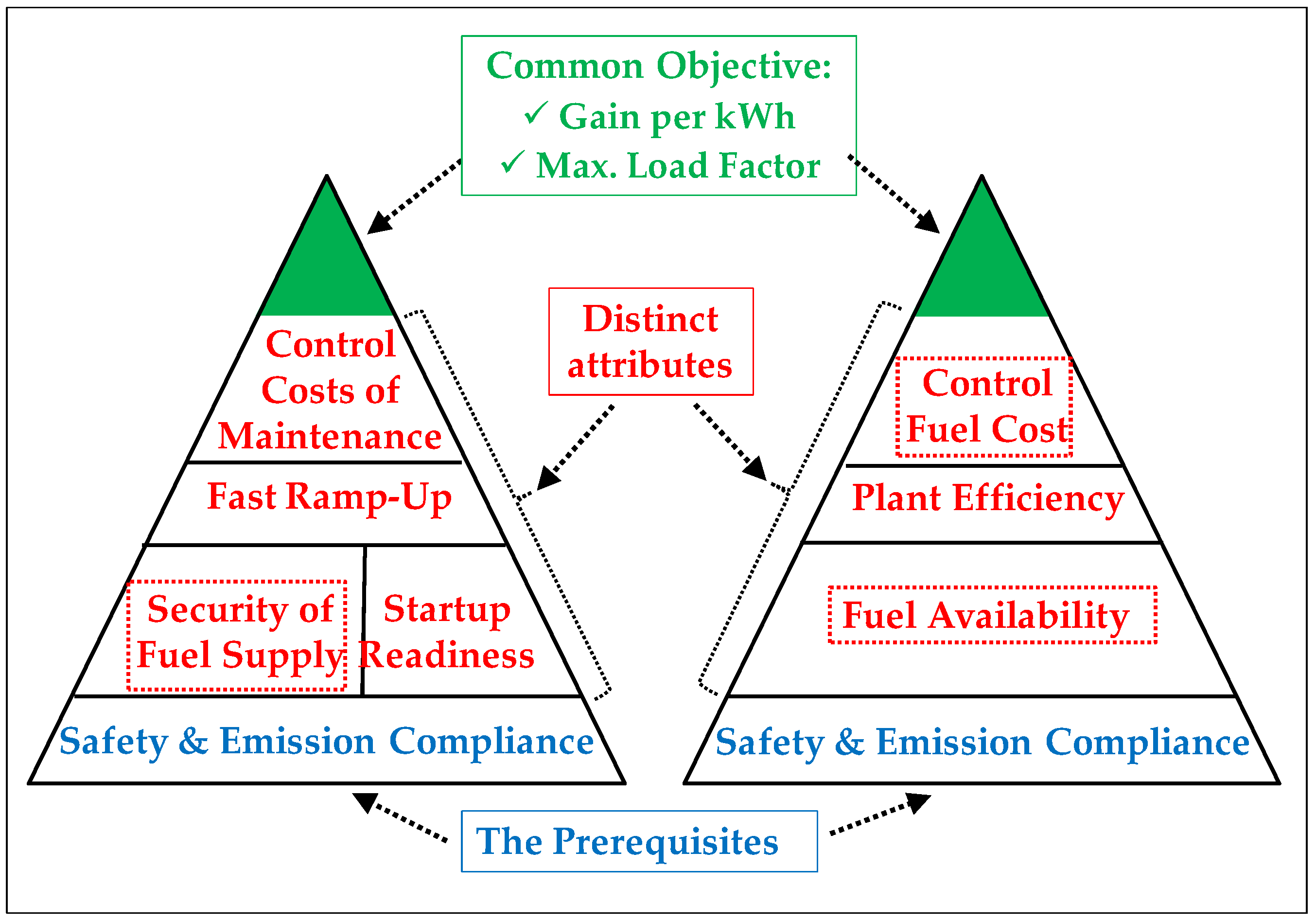
2.1. The Value of Fuel Flex in the Power Generation Market

Generically, fuel flexibility is the ability not only to accommodate a plurality of fuels but also to achieve reliable fuel changeovers. In modern power plants, these must be performed either automatically or upon simple “push-button” orders. The simplest and most common case of fuel flex is dual fuel capability, which usually involves natural gas (NG) and light distillate oil (LD) for gas turbines [6]. However, two cases should be distinguished because the expectations from a prime mover depend on to the type of service it provides:
-
Peak-shaving service is characterized by few operation hours but a constraint of permanent “dispatchability”, which is the ability to respond to changes in power demand over time, and which requires faultless startups and fast access to the targeted load; here, the plant operator’s attention is essentially focused on maintenance costs;
-
Base-load or “semi-base-load” service implies longer operation periods, during which the operator focuses on fuel cost which represents up to 60% of his O&M expenses.
Figure 1 shows the “pyramid of merits” of gas turbines intended for peak-shaving and base-load service, respectively. In both cases, the objective is to maximize the gain per kWh generated and the load factor of the unit.
For a peak-shaving service, the required qualities are: (i) startup readiness, with, at best, a black-start capability; (ii) secured access to fuel, implying a backup fuel; (iii) fast ramp-up time; and (iv) containment of maintenance costs since operating in peak-shaving mode considerably increases the “maintenance factor” due to multiple startups/shutdowns, fast load changes, and peak-load excursions. Here, a dual fuel capability represents an additional security as it will avoid the financial losses potentially caused by failures to start upon a requisition from the dispatch center. For a GT normally burning NG, which represents most cases, the second fuel can simply be a light distillate, which will be rarely used. However, in some areas lacking natural gas and light distillate (e.g., in some remote islands), the possibility to start with an alternative fuel, such as a liquefied petroleum gas, is highly desirable. However, efficiency remains an important consideration.
For a base-load or a semi-base-load service, fuel availability is also essential, but the focus is more on securing an uninterrupted supply of large fuel volumes and on minimizing fuel cost. Indeed, GTs serving large industrial plants such as refineries, petrochemical plants, or ironworks, usually operate for long periods of time, sometimes non-stop for an entire year. It is where the access to an alternative but also economic fuel acquires its full value.
The purpose of this paper is therefore to explore fuel flexibility in all its forms by highlighting the gains it can bring to many industrial sectors, especially when this quality is combined with efficient energy conversion methods, including cogeneration and combined cycles, and smart uses of residual or low-grade secondary energies [7].

2.2. Inherent Strengths of Gas Turbines Favoring Fuel Flex

Contemporary gas turbines operate according to the Brayton cycle, in which the heat addition step is made by combusting a fuel in a continuous flow of air [8]. For several reasons, this cycle is very propitious for fuel flexibility. At first, the three cycle steps (compression; combustion; expansion) are performed sequentially and in separate sections of the machines. Once the targeted load is reached, both air and fuel enter the combustors at constant flow, temperatures, and pressure, creating stationary aerodynamic and thermal patterns that greatly aid flame stability. These stable conditions and the absence of any moving part in the combustors provide a fairly large amount of room to conceive versatile combustion systems capable of matching a plurality of objectives, the most important being complete combustion, low NOx emissions, and multifuel capability, which is the focus of this article. In addition, a large portion of the combustion testing activity can be made on single combustor assemblies, separately from the rest of the machine, which enables accelerated developments of new combustion concepts or designs [9,10].
Boilers also feature continuous flow and permanent flames [11] and are greatly fuel flexible. However, a main difference is that GTs operate under pressure (up to 30 bars) and use hot combustion air, resulting in faster and more complete combustion kinetics, even when dealing with difficult fuels. The flames are therefore shorter, so the combustion chambers are of much smaller size. Moreover, the combustion heat is directly converted into mechanical power as the combustion gases themselves act as the driving fluid that rotates the machine shaft. On the contrary, the energy conversion in boilers proceeds through several heat exchanges that require very large surface areas, entailing strong thermal inertia and large transient expansions/contractions, imposing much slower temperature changes, i.e., slower load changes. These differences are also important because the much smaller hot parts of GTs can be fabricated using advanced materials, such as single crystal superalloys that are internally cooled and coated with thermal barriers [12,13,14,15,16,17]. The small, sophisticated turbine blades and vanes can withstand much higher mechanical strains and temperatures than boiler tubes, as well as steeper thermal transients, opening the way to (i) elevated cycle pressures/temperatures and hence high efficiencies that are essential for base-load operation; and (ii) fast starts/load changes that are key for peak-load service [18,19]. Finally, the compactness and modularity of gas turbine units are additional advantages that explain their high power-to-weight ratio and their short fabrication and erection times [20].
Turning to reciprocating engines, their combustion process is intermittent with alternations of several strokes and intermediate ignition events [21]. Due to the need of repetitive ignitions, those engines are specialized for certain classes of fuels with specific ignition properties. While spark-ignited (gasoline and gas) engines require fuels that are resistant to auto-ignition (i.e., with high octane indices) to avoid knocking [22,23], diesel engines need autoignitable fuels (i.e., fuels with high cetane indices) to avoid difficult startups and smoke emissions [24,25,26]. Gas turbines are free of these constraints as they operate with permanent flames and with large air excesses. Consequently, they emit no smoke and virtually no CO/UHC—even when they burn difficult liquid fuels—thanks to their air atomization systems. The PM content at the exhaust of gas-fired GTs is very low and has even been found to be lower than in ambient air, owing to the air filters at the compressor inlet [27]. While the rotary movement of reciprocating engines is created by pistons whose rings rub against cylinder walls, GT shafts rotate on hydrodynamic, friction-free journal bearings [28]. Another difference is that GT combustion liners are air-film cooled, which largely prevents flame quenching effects on their walls [29]. Although internal combustion engines boast interesting efficiencies as stand-alone machines [30,31], they release exhaust gases at medium temperature levels, which allows for only moderately or weakly efficient heat recoveries [32]. In contrast, gas turbines of the heavy-duty family (“HDGT”) that are designed with moderate compression ratios have relatively high exhaust temperatures (550–620 °C). Therefore, they can drive “topping” cycles and discharge their combustion gas into heat recovery boilers to deliver heat to “bottoming” steam cycles or cogeneration units, resulting in high overall efficiencies [33,34]. However, a definitive advantage of reciprocating engines is that their fuel does not need to have been compressed before injection in the engine.
Finally, the low fuel/air ratios and the large stall margins of HDGTs allow them to accommodate large fuel flowrates, thus enabling the combustion of low-BTU fuels in addition to medium- and high-BTU fuels [35,36]. All these design factors that favor the fuel flexibility of gas turbines represent the basic capital on which it has been possible, historically, to build a large fuel portfolio [37], thanks to continuous efforts made over years in designing and testing. As a result, these machines have gained wide fuel flexibility and have been sometimes nicknamed the “omnivorous” prime movers [38].

2.3. Technologies and Designs Underlying Fuel Flex

Validating the use of an alternative fuel in a gas turbine requires a somewhat holistic approach as one must address multiple and often interrelated design and operational aspects. Figure 2 sketches a gas turbine unit with its main fuel accessories and lists the essential operational functions to perform [39].
Adding a second fuel needs not only a dual fuel system [6] but must also meet additional requirements, which are (i) performing successful fuel changeovers [40]; (ii) keeping operation safe; (iii) protecting machine integrity; and (iv) staying emission compliant.
All these four aspects deserve specific considerations.

2.3.1. Reliable Operation with Dual Fuel Systems

Gas turbines are generally qualified as “dual gas” when they burn two gases and “dual fuel” when they burn one gas and one liquid. However, “dual fuel” is also a generic terminology to designate the capability to burn two fuels, regardless of their physical states.
  • Dual Gas Systems
An essential datapoint for the reliable and safe combustion of any gaseous fuel is its “Wobbe Index”, and more precisely, its “Modified Wobbe Index”, which governs the sizing of the gas fuel system [41] and more generally the interchangeability of gas fuels in industrial and domestic applications [42]. These indices are defined as follows:
WI = LHV/SG0.5
MWI = LHV/(SG0.5 × Tg0.5),
where SG is the specific gravity of the fuel (a dimensionless property, independent of the temperature) and Tg its absolute temperature (Kelvin). The MWI decreases when the temperature increases.
The MWI is a key datapoint to properly manage the use of different fuel gases in a given piece of combustion equipment. Indeed, the calorific power being transported by the gas, which determines the power output of the GT, is a function of (i) its MWI; (ii) the nozzle pressure drop (i.e., essentially the gas feed pressure); and (iii) the total section area of the set of orifices of the gas nozzles (i.e., the diameter and number of these orifices).
Since the gas feed pressure is limited in a certain range, and the geometry of the nozzle orifices is fixed for a defined hardware, if the MWI of the alternative gas differs too much from that of the first gas, there is a need to add secondary nozzle caps with suitable orifice diameters. Incidentally, the combustor plates of gas turbines are large enough to allow for such additions, which is an advantage of GT construction. More specifically, a sound engineering practice recommends limiting the MWI variations to ±5% for a given set of gas nozzles as a measure to avoid any damage of combustor subcomponents [43,44]. Indeed, the nozzle pressure drop is proportional to the kinetic energy of the injected gas; thus, for a given nozzle set, setting the MWI around a defined value and controlling the gas pressure keeps the flame at a suitable distance from (i) the gas nozzle tip and (ii) the end portion of the combustion chamber, namely, the transition pieces. The MWI also conditions both the aerothermal patterns and the heat release process; it consequently affects flame stability and thermoacoustic activity [45,46].
When the MWI numbers of two gas fuels differ by slightly more than 5%, it is possible to reduce this difference by heating the higher calorific gas. If, for example, the MWI gap is 6%, the necessary temperature increase, ΔTg, given by Equation (2), will equal:
ΔTg = 2 × Tg × Δ(MWI)/MWI ≈ 2 × 300 × 0.06 = 36 K.
More generally, one will use a dual-gas system, which consists of a set of double-gas nozzles and possibly two gas manifolds and two sets of gas valves (Figure 3) [47].
  • Liquid Fuel (LF) Systems [39]
The high-pressure portion of the LF circuit is fed by a low-pressure forwarding circuit. It comprises a positive displacement HP pump, the flow rate of which is adjusted by recirculation through a by-pass valve. In some designs, a mechanical device called “flow divider” is used to distribute equal fuel flows to all combustors; they can be of the linear type, as represented in Figure 4, or circular.
Some atomization air is bled from the GT compressor and boosted by an auxiliary compressor to have the liquid fuel finely sprayed into the combustor and to suppress soot formation [48].
Virtually all liquid fuels, including biodiesel but excepting alcohols, have relatively close heating values; this dispenses from changing the fuel accessories and the fuel injectors when passing, for instance, from a naphtha to a No.2 distillate fuel.
Viscous LFs can be heated (in the upstream low-pressure section) to reduce their viscosity and enable their proper atomization into the combustors, thus preventing smoke emissions [39]. However, the heating temperature must not exceed the incipient pyrolyzing temperature of the fuel, which depends on its composition, the usual maximum being 130–140 °C [43].
Conversely, some light liquids (naphtha, alcohols) are low-viscosity fuels and have poor “lubricity”, a property which is evaluated via the “HFRR test” [49,50]. If it is insufficiently “lubricious”, dosing a lubricity improving additive may prove necessary.

2.3.2. Ensuring Operation Safety

  • Essential safety measures
As indicated in Figure 2, GT enclosures must be equipped with adequate ventilation and fuel leak detection systems, as well as CO2 inerting systems in emergency case.
The essential safety data for fuels are (i) the lower and upper explosion limits (LEL-UEL), the LEL being the critical datum; (ii) the autoignition temperature (AIT); (iii) the minimum ignition energy (MIE); and, for liquids, (iv) the boiling point and (v) the vapor pressure (measured at e.g., 38 °C) [51]. The LEL of gas or vapor mixtures can be estimated by Le Chatelier’s law in the absence of inert compounds [52] and based on empirical models in presence of inerts [53]. It is mandatory to verify that the installed gas detectors fit with the vapors of the fuel being burned [54,55]. The prediction of the AITs of gas mixtures in GT conditions, i.e., at elevated temperatures and pressures, is a complex subject on which interesting progress is nevertheless being made thanks to Artificial Intelligence [56].
In the case of a dual gas machine, a gas changeover is preceded by a purge of the fuel circuit using compressed air extracted at the GT compressor discharge. Since this compressed air is hot, nitrogen is used instead for purging if the gas has a low AIT or MIE. This point will be revisited when dealing with hydrogen applications. Similarly, before transferring from a volatile liquid to a gaseous backup fuel, and vice versa, a purge of the liquid fuel line by a light distillate is performed to avoid uncontrolled flash vaporization of the volatile liquid. In case of leaks, LPGs (butane/propane) and volatile fuels (naphtha/NGL) can generate hazardous liquid pools and vapor clouds that are denser than air and may stagnate at low points [57], requiring highly sensitive vapor detectors [55].
As far as product and operational safety is concerned, an international safety standard (ISO 21789:2022) has been developed at the initiative of the UK HSE and implemented in the late 2000s to facilitate the integration of some recent EU regulations in GT designs, especially the Explosive Atmosphere (ATEX) and Pressure Equipment (PED) Directives. This ISO standard has been updated in 2022 [58].
  • Safe Fuel temperature range
If the alternative fuel is a volatile liquid, it is a sound engineering practice to keep its temperature at about 56 °C below its bubble point to prevent vapor locks and the associated risk of pump cavitation, which is conducive to uncontrolled or hazardous operation. It is the case with naphtha, gas condensates (GC), or “natural gas liquids” (NGL) [59]. This measure is illustrated by Figure 5.
Conversely, if it is a partly condensable gas, then its temperature must be brought to about 28 °C above its dew point [43] to prevent the occurrence of a “blowpipe effect” that would devastate the combustors and possibly some turbine parts. This would occur if one were to burn incompletely vaporized LPG or a C3+ rich natural gas.

2.3.3. Staying Emission Compliant

Emission compliance is now mandatory worldwide, whatever the fuel burned.
SOx emissions and “organic” NOx emissions (generated by the fuel-bound nitrogen) are directly related to the sulfur and nitrogen contents of the fuel, respectively; these must be kept below appropriate levels. Flue gas desulfurization or “DeSOx” post-combustion technologies exist [60,61], but they are expensive and reserved in practice for boilers as they entail elevated pressure drops at equipment exhaust and GT performance penalties.
As pointed out above, gas turbines release minute CO, UHC, and smoke emissions, even with difficult fuels, including highly aromatic by-products, which will be discussed later.
Due to the firing temperature and pressure developed in their combustors, GTs tend, however, to generate high thermal NOx when they operate with diffusion flames, which is the historical combustion mode of these machines; each fuel has an own NOx index that depends on its composition and is approximately an exponential function of its (adiabatic) stoichiometric combustion temperature, “Tad,st” [62]. This must be carefully considered when envisaging an alternative fuel [63,64].
To reduce the NOx emission, up until the late 1980s, OEMs applied a “wet control”, which consisted in injecting a diluent (most often liquid water or steam) in the combustors to reduce the temperature peak (Tad,st) in the flame. However, major developments conducted in the 1980s–90s in combustion laboratories led to the design of inherently-low-NOx systems that prevent GT users from injecting any diluent or installing expensive post-combustion DeNOx systems when burning natural gas. The solution, referred to as “Dry Low NOx” (DLN) (or “Dry Low Emissions”, DLE) technologies, is based on the combustion of premixed gas/air mixtures [65,66,67,68]. Successful DLN designs must overcome a set of complex difficulties, namely, (i) avoiding lean blowouts (LBO) and flashbacks; (ii) containing CO emissions; and (iii) controlling combustion dynamics [69] while (iv) keeping hardware durability (Figure 6a).
Flame flashbacks possibly occur according to different mechanisms: by autoignition in the premixed zone due to a too-low AIT of the fuel or combustion instabilities (combustion dynamics); and by retro-propagation in the core flow or through boundary layers [70]. Combustion dynamics are due to an interaction between unsteady aerodynamics and heat release fluctuation processes causing pressure oscillations that can resonate in the combustor cavities and cause mechanical wear/damage [71]. Since premixed flames have, by design, a narrow lean richness range, they are more sensitive to dynamics than diffusion flames that have broad richness ranges with lower risks of simultaneous extinction of all points of the flame front.
A typical evolution of NOx control is outlined in Figure 6b. Ongoing efforts are being made with success to improve the operability of DLN systems, namely, in two directions: (i) expanding the range of emission compliance to lower GT loads, the so-called “Minimum Emissions Compliance Load” (MECL) or, more simply, the “Turn Down” (see inset in Figure 6a); and, as regards fuel flexibility, (ii) extending the capability of those systems to non-NG fuels by improving the aerothermal patterns of the combustors to counteract the adverse combustion effects described above [72].
Regarding low NOx systems for liquid fuels, it must be noted that C5+ hydrocarbons have low AIT data as compared, e.g., to methane. Therefore, “Dry Oil NOx” systems are very challenging to design for trouble-free operation. For some alternative fuels, the sole option is therefore to inject a diluent (most often liquid water or steam) in the combustors to reduce the temperature peak in the flame and correlatively the emission of NOx.

2.3.4. Ensuring Machine Integrity

The design and operational measures covered in Section 2.3.1 and Section 2.3.2 enable the avoidance of defective combustion and associated component damages in dual fuel configurations. However, many alternative fuels contain impurities. Some of them (e.g., coke oven and blast furnace gases: COG; BFG) contain inorganic particles that must be removed by proper filtration as they can inflict severe erosion to turbine parts [43]. Some others contain sulfur (e.g., sour natural gases) leading to polluting SOx emissions. Finally, some liquid fuels (crude and residual oils) contain both sulfur and traces of alkaline metals (Na, K) and vanadium (V), leading to corrosive, low-melting point salts or oxides (mainly sodium sulfate: Na2SO4; and vanadium pentoxide: V2O5) [73]. Reference [41] gives a comprehensive review of the adverse effects of fuel impurities on turbine parts and the corrective pretreatments, including filtration, desalination, and corrosion inhibition.

2.3.5. Measures Specific to the Operation on Hydrogen-Rich Gases

Additional measures relating to the combustion of hydrogen taken to suppress the risk of hot parts overheating and material embrittlement will be addressed in Section 4.

3. Creation and Growth of the Fuel Portfolio

3.1. General Overview

Since the 1960s, land-based gas turbines have gradually occupied a wide space of alternative fuels [37,38,74,75,76,77,78]. Figure 7 gives a synoptic view of the current extension of that fuel portfolio.
To be able to bring together both gaseous and liquid fuels in a same chart, the chosen ordinate is the mass percentage of hydrogen, the abscissa being the mass LHV. Since the dihydrogen molecule has both the highest mass LHV (120 MJ/kg) and contains, by definition, 100% elemental hydrogen, it occupies the top right corner of that chart.
Table 1 lists most of these fuels along with the following data: (i) their origins; (ii) the acronyms used in this paper; (iii) their gaseous/liquid state; and (iv) their level of purity, namely, their ash-free or ash-forming character. This table also includes the two conventional fuels (natural gas and light distillate).
Historically, the acquisition of this portfolio started from pipeline NG and LD and has been a gradual process that took place over several decades. The additions of the different fuels generally were/are in response to specific demands from industrial actors. The most frequent opportunities are related to by-products of industrial processes available in substantial volumes. These come from multiple economy branches: the oil and gas, petrochemical, and metallurgical sectors; the processing and gasification of coal, of biomass or even municipal solid wastes.
The plants in demand typically generate streams of combustible by-products that have valuable energetic potentials but were previously either wasted—e.g., by flaring—or used in few profitable applications, until more cost-effective usages became feasible [79]. Conversion to heat and power is one of them: thermal power is generally used to cover domestic needs (chemical, petrochemical, or food processes), while the electric power is intended for self-consumption and sometimes for export.
Historically, the beneficiation options involved the combustion of these by-products in utility boilers, but more efficient GT-driven cogeneration units gradually displaced these boilers. This displacement began around the 1970s in the USA, where GT started their brisk development (with efficiencies reaching then exceeding 25%), then roughly in the 1980s in Europe and during the 1990 s in Asia. It was accelerated by emerging regulations encouraging cogeneration as a virtuous tool for improving energy effectiveness [80].
Recently, gaseous and liquid biofuels, resulting from the processing of a wide variety of biomass feedstocks, have emerged as potential GT fuels. The reference [81] offers a thorough technical coverage of the raw materials and processing technologies that are currently involved in the production of biofuels.
Before a given candidate becomes “entitled” as an actual alternative GT fuel, it must pass rigorous analyses and lab combustion tests, but subsequent pilot field tests are also highly advisable. These tests became increasingly focused on emission compliance due to the rise of environmental regulations worldwide. In the 1970s, the first USEPA recommendations—the so-called Clean Air Act—began setting a NOx emission limit of 75 ppm to fight against the episodes of “smogs” in big cities and enforced more stringent limits (42 or 25 ppm) in critical “non-attainment areas” (California, Texas) [82]. Since DLN technologies were industrially available only in the early 1990s (see Section 2.3.3), DeNOx was formerly achieved in GTs by steam injection. To that end, medium-pressure steam was extracted from the heat recovery steam generators. Resorting to the SCR (Selective Catalytic Reduction) technology was necessary to reach the lowest NOx codes [83].
When the pilot tests of an alternative fuel candidate prove successful, they result in “win–win” opportunities for both the requesting industrial partner and the GT OEM. Sometimes, it becomes the starting point for a closer relationship. For instance, the power generator Groupe E (formerly ENSA), which has its headquarters in Neuchatel (Switzerland), has greatly contributed to the successful testing of several alternative fuels [84,85,86].

3.2. The Gas Fuel Portfolio

Figure 8 illustrates the way the map of gaseous GT fuels has been extending over the years. The MWI Index (Equation (2)) has been taken as ordinate and the mass LHV as abscissa. In this new representation, hydrogen has the highest mass LHV and lies on the right borderline while butane has the highest MWI and marks the higher boundary.
Fuel gases can be classified as HCV fuels (having LHV ranging from 50 to 120 MJ/Nm3), MCV (11 to 50 MJ/Nm3) and LCV ones (below 11 and possibly down to 3 MJ/Nm3). It is worth mentioning that this classification is not an absolute one as some GT OEMs use different scales.
In addition, this classification would change if one would consider mass-based LHVs instead of volume-based ones: for instance, hydrogen would pass from the LCV to the HCV category since its LHV is 120 MJ per kg but hardly 11.7 MJ per Nm3.
Since the 1960s, the sphere of gaseous GT fuels has been expanding, starting from the historic “island” of natural gas, which consists essentially in methane and traces of C2+ hydrocarbons. It currently embraces HCV, MCV, and LCV gases. The backup fuel is generally a light distillate.
The expansion of this gas portfolio has occurred in three directions: towards higher and lower calorific fuels and higher hydrogen contents.
  • Expansion towards high-calorific fuels:
This family includes the following products:
-
Commercial LPGs (propane, butane, and mixtures thereof) mainly come from the processing of NG and the atmospheric distillation of crudes. They are generally burned after vaporization. Their combustion in variable amounts in GTs is interesting as it allows matching the offer to the demand of LPGs namely in summer [87];
-
Refinery fuel gases (RFG) [88] as well as petrochemical net gases (PNG) [87,88,89,90] mainly contain C2 to C4 alkanes and/or olefins, in addition to variable amounts of H2; they stem from fluid catalytic cracking (FCC) or steam catalytic cracking (SCC) units. They are produced continuously and yield high GT performances.
  • Expansion towards low-calorific fuels:
This family involves gaseous streams in which the combustible species (mainly CH4, CO, and H2) are diluted by elevated amounts of N2, H2O, and/or CO2. Their main representatives are the following:
-
“Lean natural gases” stem from some NG wells or coal mines and contain CH4, N2, and CO2 [37]; they are medium- or low-BTU fuels; their combustion after compression is interesting if the sale of the kWhs exceeds the cost of compression that is only partly compensated by the extra power produced by the expansion in the turbine;
-
Biogases are produced in breeding farms or in landfills; they can be cleaned (H2S removal) and burned in microturbines to cover power self-consumption; recently, they have been transported and injected in natural gas networks [91,92,93,94];
-
Coke oven gases (COG) come from the pyrolysis of coal for the preparation of metallurgical coke and contain H2, CH4, CO, CO2, and H2O. They contain dusts that must be filtered and tars that must be removed by condensation/water scrubbing [95,96,97].
-
Air-blown syngases (SG) are very lean gases which contain mainly CO, N2, H2O, and H2 and come from the gasification of coal/lignite [98,99,100,101,102], or biomass [103,104,105], or even solid municipal wastes [106,107,108]; oxygen-blow gasification is applied to very difficult solids (HFOs and bituminous coals) and yield syngases with higher LHVs [101]. Syngases from coals and HFOs must undergo drastic clean-up processes to remove particles, sulfur, nitrogen, and heavy metals;
-
Blast furnace gases (BFG) are also lean fuels and are loaded with high concentrations of CO2 and H2O; due to their high level of dust, they also need very efficient clean-up facilities before injection in GTs [109,110,111].
  • Expansion towards higher H2 contents:
Both steam cracking and aromatization units in petrochemical and refineries release gaseous byproducts that contain variable amounts of hydrocarbons and hydrogen. These streams are gathered in a gas network and are called “fuel gas” or “net gas”; they are used as secondary energies in the plant utilities equipped with gas turbines. The amount of H2 can reach 70% or even 95%: this point is important and will be brought up again when dealing with the development of the hydrogen economy.

3.3. The Liquid Fuel Portfolio

Figure 9 shows a map of most popular alternative liquids, which can be split into fossil and biogenic products. The (non-linear) ordinate of this chart is the hydrogen content. Biofuels have, in general, lower calorific value and do not have higher hydrogen contents than fossil fuels, both points being due to the presence of oxygen atoms in their molecules.

3.3.1. Fossil Liquids

The overwhelming majority of fossil liquids stem from O&G production, oil refineries, and, to a lesser extent, from petrochemical plants. A sketch of a typical natural gas chain is given in Figure 10 and a diagram of a modern refinery in Figure 11.
Fossil liquids can be categorized according to their volatility and aromatic character:
  • “Super-Light Distillates” (SLHCs) include three main products:
    -
    Naphtha’s that stem from the distillation of crude in refineries;
    -
    Gas condensates (GC) that come directly from gas fields (Figure 10);
    -
    Natural gas liquids (NGL) that originate from the stripping of raw NGs [112].
Naphtha and NGLs are high-grade, clean fuels and belong to the same refining pool as gasoline; they yield GT performances similar to those of #2 distillate oils. GCs are raw products that are mainly constituted by light hydrocarbons but can contain some heavy ends, such as light crudes. All require specific safety precautions, due to their high volatility, and the dosage of a “superlubricant” additive to make up for their low lubricity (see Section 2.3.1) [113]. Startups and shutdowns are made using a No. 2 distillate.
Naphtha has been largely used as GT fuel in India and Pakistan, where there are surpluses of gasoline and shortages of NG. More generally, SLHCs are “bridging fuels” to natural gas or to LNG in regions with high development potential but a lack of NG resources or immature pipeline networks. Incidentally, we should note that naphtha is not named a “super light hydrocarbon” in the in the oil business but is instead categorized as a light distillate, like gasoline (Figure 11).
  • Light distillates (LDs) are classified as “middle distillates” by the oil business. They consist of kerosene and #2 distillate oil; their use in GTs does not require the additives package that is necessary for aircraft and diesel cars. Kerosene’s and No. 2 distillate oils are “straight-run” refinery products that originate from the atmospheric distillation of crudes (Figure 11); they are prime-quality, expensive GT fuels. While No. 2 distillate is the conventional liquid fuel for heavy-duty GTs, kerosene is the preferred one for aeroderivatives in consideration of its still-higher purity. However, the expensive kerosene is generally used only on some rare islands where No. 2 diesel is not demanded as car fuel. Finally, another refinery cut called “light cycle oils” (LCOs) can be integrated in this group although it is of much lower grade; LCOs are not straight-run products as they come from the cracking of vacuum distillates (Figure 11) and are rich in aromatics and polyaromatics. Their possible use in gas turbines is described below in the paragraph devoted to aromatic fuels;
  • Heavy distillate Oils originate from the vacuum distillation of crudes [87]. They are available from refineries that do not have “deep conversion” units; they must be burned after heating to reduce their viscosity for proper atomization;
  • Crude oils are the raw hydrocarbons extracted from oil fields where they may be associated with C1-C4 gases (LPGs) or C5+ condensable gases (gas condensates). Their composition is variable as they can contain heavy hydrocarbon ends. Heavy crudes, especially those extracted in remote areas, do not interest refiners as they do not yield light cuts; they can be cleanly burned in GTs on the spots, using—if necessary—a combustion catalyst additive, e.g., cerium derivatives [114], to avoid a slight smoking trend;
  • Residual oils (RO) are very-low-grade refinery cuts. These ash-forming fuels can no longer be distilled and represent the “bottom of the barrel”. Due to their high SOx, NOx, and PM emissions, they are disappearing from the market, being converted into “pet-cokes” or gasified in oxygen-blown gasifiers to produce syngases (SG). Nevertheless, the combustion of HFOs in GT combined cycles generates significantly fewer polluting emissions than if using diesel engines. As mentioned in Section 2.3.4, both crudes and ROs need to be cleaned before combustion. Some low-sulfur waxy residual fuels, called “LSWR”, have been used in the Far East (Japan, Korea, Singapore…) for power generation. Efforts have also been made to alleviate the adverse effects of smoke and ash deposition on the performances of gas turbines [114,115];
  • Aromatic fuels belong either to the group of super light hydrocarbons (“BTX” and “C9+ aromatics”) or to that of light distillates (Light Cycle Oil or “LCO”):
    -
    BTXs (Benzene–Toluene–Xylene) are C6–C8 mono-aromatics. Huge volumes are also used as petrochemical feedstock for the synthesis of a large variety of commodities, including polymers, paints, and solvents. They have also been used, along with “C9+ aromatics”, as RON improvers for gasoline’s, owing to the high AITs of aromatics. However, due to the ban of aromatics in automotive fuels, they may be produced in surpluses in refineries deprived of petrochemical units; moreover, the exportation of such sensitive cuts represents a financial burden and creates EHS difficulties that can lead refiners to envisage other usages. This is where on-site power generation becomes an interesting option. A stream of such aromatic hydrocarbons, called BHC (for “Benzene Heart Cut”), with a BTX composition, have been successfully tested in a 40 MWe heavy-duty GT [84]. Subsequently, based on this successful test, a C9+ aromatic cut found an industrial application in Korea [116];
    -
    LCO (light cycle oil) tends to be produced in increasing amounts in modern refineries. Indeed, fluid catalytic crackers (“FCC”) crack heavy distillate feedstocks into lighter ones, thereby helping convert the original crude to more middle distillates and gasolines with higher RON indices. LCOs contain up to 70% aromatics (essentially in the form of di-aromatics). Their very poor cetane number and high smoking propensity strongly limits the proportion that can be added to diesel fuels and to domestic heating oil. In contrast, the combustion of LCO has been successfully tested, also in a 40 MW heavy-duty GT [84,85].

3.3.2. Liquid Biofuels

Liquid biofuels represent a prolific and promising family. Figure 12 summarizes the different production processes starting from vegetable biomass. The most popular liquid biofuels belong to three main groups: alcohols (bio-ethanol); vegetable oils (VO), and biodiesels.
The combustion of liquid biofuels in gas turbines is not a new topic but its interest has been renewed in the late 2000s, as energy decarbonation became an increasing concern [117,118,119,120,121,122,123,124]. However, both bioethanol and biodiesel are currently produced from edible substances: the former comes from sugars, corn, or wheat starches and the latter from oil seeds. This “food versus fuel” competition has raised a legitimate debate [125].
Since biodiesel and bioethanol are already used as blenders of diesel and gasoline car fuels, respectively, it looks reasonable to consider that their use for power generation, which consumes large volumes, should be reserved for small units.
  • Bioethanol comes from the anaerobic fermentation of natural sugars (grape, sugar beet, sugar cane, etc.) (Figure 12) and are often produced in surplus in some agricultural sectors and some countries. Dehydrated ethanol is fully miscible with gasoline; this property has been exploited in a bioethanol combustion test that was carried out on a 20 MW GT in India and in which naphtha was used as starting fuel and gradually blended with increasing proportions of bioethanol, up to 95% [126]. This field test demonstrated that ethanol can be burned without any trouble with NOx emissions lower than those of LD and close to those of NG (Figure 13). Bioethanol from sugar cane has also been recently burned in a 40 MW GT at Saint Pierre de La Réunion (a French ultramarine territory), although this experience is not well documented [127].
Figure 13. Summary of an Ethanol field test: ethanol/naphtha mixtures were used [126].
Energies 16 03962 g013
Brazil is the world leader for the production of bioethanol. The “first-generation” bioethanol is prepared from sugar harvested from cane fields (“first crop”). It is largely consumed as automotive fuel in Brazil, where the fleet of flex-fuel cars can accept up to E100 fuel (i.e., 0% gasoline). However, the “food versus fuel debate” has prompted the use of a “second crop” source of ethanol, which will exploit the lignocellulose contained in bagasse as raw matter [128]. Bagasse is the fibrous substance left after the juice of the sugarcane plant has been harvested; it will be processed in “ethanolic biorefineries” that will produce “second-generation biofuels” [129].
  • Methanol was formerly prepared by the distillation/carbonization of wood (charcoal industry) and was named “wood alcohol”. However, currently, 98% of methanol comes from the reforming of methane and has thus a non-bio, fossil origin. It can also be produced through the coal-to-liquid or biomass-to-liquid (CTL/BTL) routes. It is a feedstock to produce FAME biodiesel, as discussed below. Kinetics simulations show that it could be burned in GTs [130]. However, its high vapor pressure (13 kPa at 20 °C) and acute toxicity are major obstacles for this application.
  • Dimethyl-Ether
DME also originates from the CTL/BTL routes. It is gaseous at room temperature, with a vapor pressure of 5.10 bars at 20 °C. It has as some analogy with LPG as a potential fuel, as set out below, and has been used as domestic fuel in China. Kinetics simulations are also available [130] and a successful field test by British Petroleum on a 120 MW GT has been performed [131].
  • Biodiesels
Biodiesels are “Fatty Acid Alkyl Esters” obtained by trans-esterification of vegetable oils (VOs) using methanol (FAME: fatty acid methyl esters) or, more rarely, ethanol (FAEE: fatty acid ethyl esters). VOs are sourced from a large variety of seeds (soybean, rapeseed, palm, coco (copra), corn, sunflower, cotton, peanut, sugarcane (bagasse), canola, etc.), depending on the world regions [132]. They have variable chain lengths and double bond numbers. This VO source is often complemented by triglycerides: “yellow greases” coming from recycled food wastes or even by animal fats (“tallow”).
Various biodiesel field tests were performed, namely, in 2007 in Switzerland on an E-class GT [86], in 2009 at Duke Energy Carolinas on an F-class G, and in 2021 at Göteborg Energi [133]. These field tests have demonstrated the excellent behavior of FAME biodiesels, including during “cold” and “hot” startups performed with 100% biodiesel, as shown in Figure 14. The inset in that figure sketches a typical molecule of FAME biodiesel with a single double bond.
A question arose as to whether the thermal NOx indices of biodiesels, i.e., their combustion temperature “Tad,st“ (see Section 2.3.3), are lower or higher than those of No. 2 distillates. Both field test results and detailed kinetic simulations showed that the values of Tad,st are always slightly lower for FAMEs than for hydrocarbons with the same degree of insaturation (alkanes, alkenes, trienes, alkylaromatics), irrespective of the chain length (Figure 15) [134]. This point is interesting as it contrasts with the results obtained for some diesel engines, in which another physical process prevails, which is the higher compressibility bulk modulus of biodiesel that alters the ignition time and tends to increase NOx [135].
  • Vegetable Oils
So far, VOs have not been entitled as GT fuels, the main reasons being (i) their high viscosity and the risk of chemical degradation by pyrolysis when heating them to make them more fluid; and (ii) their content of metallic contaminants (K and Ca) that often exceed GT fuel specifications (Section 2.3.4) and cannot be completely extracted by water-washing as they are partly oil-soluble, which makes their removal difficult.

3.3.3. Similarities between Biofuels and Fossils

As regards gas turbine applications, there are some interesting commonalities between biogenic and fossil fuels (Table 2).
For instance:
-
Bioethanol versus naphtha: Anhydrous ethanol is fully miscible with naphtha, i.e., with gasoline. This is interesting in countries such as India where naphtha is often used as base-load GT fuel due to the scarcity of natural gas and distillate fuels and, on another hand, the fact that bioethanol is available through the fermentation of discarded cotton [136];
-
Biodiesel versus light distillate: Biodiesel is fully miscible with light distillate oils, i.e., with diesel fuels. It is more lubricious than diesel fuels but, due to its higher power as solvent, it can be aggressive against certain elastomeric seals used in fuel circuits;
-
Vegetable oils versus crude oils: VOs are partly miscible with crude oils [137] and have several similarities with them: both are unprocessed liquids that contain long molecules with many chemical functions and are contaminated with metals. However, there are important differences. Indeed, contrary to crude oils, vegetable oils contain no heavy metals (vanadium, nickel) and very little sulfur and nitrogen; their metallic contaminants are partly oil-soluble and, when they are heated, they do not distil but tend to degrade more rapidly than petroleum cuts by pyrolysis. For these reasons, VOs are not currently used as a GT fuel; they can be burned in boilers with some precautions due to the generation of corrosive low-melting point salts (potassium and calcium chlorides).

4. The Contribution of Gas Turbines to the Hydrogen Energy Move

Hydrogen is an energy carrier and not a primary energy as there are very scarce natural sources thereof; the rare reservoirs of hydrogen originate from chemical reactions inside the earth crust and are sometimes referred to as “natural H2”or “white H2” [138].

4.1. The “Hydrogen Rainbow”

The main supply of hydrogen is currently from fossil fuels via two main routes which are (i) the steam reforming of natural gas that yields “grey” or “blue” H2, depending on whether the resultant CO2 is captured or not; and (ii) the gasification of coal which leads to “black” (or “brown”) H2. These processes are very energy intensive. However, an increasing number of projects are conducted or planned to produce H2 by the electrolytic splitting of water into H2 and O2, using either solar power (“yellow” H2), wind/hydro power (“green” H2), or nuclear power generated during off-peak hours (“pink” or “purple” H2). There are in fact numerous approaches under investigation to produce hydrogen, resulting in the so-called “H2 rainbow” (Figure 16) [139].
The development of hydrogen as an energy vector must deal not only with its production, but also with the delicate development of all the infrastructures that are required for its storage and transportation, as well as its conversion into power or its adaptation to cars. This vast theme, along with the associated feasibility and safety aspects, fall by far beyond the scope of the present paper. This set of topics generates an exponential number of publications. Extensive information is available from different sources, namely, from the EU commission [140], the USDOE [141], or the UK government [142].
The advent of hydrogen of the green, yellow, or pink type as a universal substitute for fossil fuels would procure a dramatic solution to some critical environmental problems. Indeed, it would provide not only the sought route towards carbon-neutral economies but also a radical solution to endemic urban pollutions by suppressing all emissions of VOCs, CO, SOx, O3, PAH, and soot particles.
However, the development of the “hydrogen economy” must overcome several technology challenges since, apart from high R&D investment needs, hydrogen has critical physical and chemical properties which impact the safety of its entire application chain, i.e., its production, storage, transportation, and end usages. With regard to the performance and the safety of combustion, hydrogen features a set of challenging properties, which are as follows: a wide flammability range; a high diffusivity with metallurgical impacts on materials; and a very-high flame speed and low ignition energy. In this respect, Table 3 shows a comparison between hydrogen and methane [143,144].

4.2. The Possible Role of Gas Turbines

As discussed below, gas turbines can burn both pure and blended hydrogen and, as discussed above, they boast high energy effectiveness in combined cycles as well as fast installation. Therefore, these machines are placed in the front of the energy scene, as they are in position to boost the deployment of hydrogen energy in the power generation sector. Figure 17 shows a possible energy system involving gas turbines: green, yellow, or pink hydrogen is produced in electrolysis “power-to-gas” units fed by wind, PV, and nuclear plants; it is partly used as an automotive fuel and partly mixed with NG (and possibly with some carbon-neutral biogas streams) in gas networks which, in turn, feed “gas-to-power” GTCC nodes (or large Fuel Cell units) [145].
Energy wise, H2 is also a very singular fuel since; on one hand, it has a weak volume LHV (10.7 MJ/Nm3) that would place it in the category of LCV gases; however, on the other hand, it boasts the highest mass LHV (120 MJ/kg) of all fuels [146].
Moreover, NOx emissions pose a serious challenge due to the addition of two effects:
-
Hydrogen flames are very hot (Figure 18a) [147]. Indeed, one molecule of H2 generates three times less molecules of combustion products than does CH4 (Table 3); therefore, its stoichiometric combustion temperature (at the flame front) is much higher (2120 °C versus 1950 °C, in E-class GT conditions) since its combustion heat is transferred to one molecule instead of three. This is why hydrogen generates much higher NOx in diffusion flames than methane;
-
Conventional Dry Low NOx systems based on the current fuel/air premix devices are defeated due to the very fast flame speed (Figure 18b) [148] that results in very short flames (Figure 18a) but causes very difficult flashback issues (see Section 2.3.3).
Figure 18. (a): Flame front temperatures and (b) laminar flame speeds of H2-CH4 mixtures.
Energies 16 03962 g018
Therefore, the combustion of hydrogen in GTs requires innovative approaches to design appropriate DLN systems likely to avoid flashbacks and secure proper flame holding.
It should be noted that the combustion of ammonia (NH3) as a potential substitute of dihydrogen is not feasible as it would generate huge amounts of organic NOx (Section 2.3.3). Consequently, an intense activity has been deployed for several years to develop “hydrogen-capable” low-NOx combustors. To prevent flashbacks, current designs focus on multiple small H2/air jets passing at high velocity through small injection orifices and become intimately mixed with corresponding air jets. Such devices, based on “micromix” injectors, are very promising; they enable the fine control of the spatial distribution of the fuel richness, down to the sub-millimetric scale, and minimize the risks of both core-flow and boundary-layer flashbacks (see Section 2.3.3). Figure 19 shows such a device that has been successfully lab tested [149,150]. Other similar designs exist [151,152].
Another important specificity of hydrogen resides in the fact that due the intrinsically high thermal conductivity of gaseous H2O at high temperature, there are intense convective heat exchanges between the H2O-rich combustion gases and the hot parts of the expansion turbine; this tends to increase metal skin temperatures and requires the reinforcing of the cooling of the hot parts to avoid premature creep and thermal fatigue effects.
Finally, hydrogen can cause the embrittlement of some metallic alloys, depending on pressure and temperature, so compatibility testing is required [153].

4.3. Exploiting the Experience Gained with H2-rich fuels

From a historical perspective, the ability of gas turbines to handle industrially H2-rich gases and eventually pure hydrogen is demonstrated by the wide experience that has been gained over the years in tens of refining and petrochemical plants burning by-process gases worldwide, as discussed in Section 3.2.
For instance, Spanish, UK, Korean, and Chinese refiners/petrochemists have managed major revamping programs of their utilities in the 1990s and 2000s, replacing aging refinery boilers with CHP units driven by 40 MW-class and sometimes 100 MW-class gas turbines that can burn up to 70% H2 rich gases [87,88,89].
However, the “hydrogen fleet leader” is a 40 MWe gas turbine installed at the Daesan Petrochemical Plant in Korea (Figure 20) [154]. In the 1970s, this site hosted a first petrochemical unit (marked as #1 Pet-Chem Unit in that figure) equipped with a naphtha cracker along with a 25 MWe gas turbine (#1 GT), which began to burn a C3-rich “petrochemical net gas” (PNG) coming from that cracker. Thereafter, the petrochemical company (Samsung General Chemicals at that time) installed an aromatization reactor that generated a net gas highly rich in H2 (H2-rich PNG) and was associated with a 40 MWe gas turbine (#2 GT) that drove an additional power unit (marked as #2 Pet-Chem Unit). Since 1997, this second GT has been reliably running for hundreds of thousands of hours on that H2-rich PNG with hydrogen contents up to 90–95%. Although this machine operates with conventional diffusion flames and is equipped with DeNOx steam injection, this experience has amply demonstrated, with a hindsight of six years at present, the feasibility of operating a GT with nearly 100% hydrogen from both safety and reliability standpoints.
This plant also illustrates the multifaceted fuel flex and the high integration potential of heavy-duty gas turbines since (i) the two GTs use a C4-LPG as startup fuel; and (ii) the first one burns a C3-rich gas stream produced by the naphtha cracker and its flue gas serves as hot fluid to heat the same cracking reactor.

5. Conclusions

This paper aimed to offer an extensive view on the wide fuel flexibility acquired by land-based gas turbines in the power generation sector.
First, it has provided essential technical keys by which to understand the reasons for this distinctive capability. To highlight the value of fuel flex in modern electrical grids, this quality has been put in perspective with the set of duties expected from modern power generators. Furthermore, to understand how gas turbines can accept multiple fuels, basic aspects of the Brayton cycles and GT combustion systems have been set out.
Then, this paper reviewed the various classes of products that make up the GT fuel portfolio, as well as the corresponding applications, outlining how this fuel portfolio has been expanding over years. The resulting range of alternative GT fuels cuts across many sectors of the economy worldwide, overlapping with most industrial and farming activities where gaseous or liquid combustible streams have been made available.
This outcome relies on the great adaptability of the gas turbine product but has been made possible by intense engineering work, experience accumulation and extrapolation, lab testing, and validation on the field. It has also been favored by market opportunities and fostered by the vivid development of cogeneration and combined cycles as effective energy conversion systems.
In the future, the development of new energies, especially hydrogen and second-generation bio-sourced fuels, is expected to preserve the assets of land-based gas turbines in the power generation sector and reinforce their role in the energy transition. This is despite the irresistible but indispensable rise in power of renewable energy alternatives, which tend to displace thermal generation.

Funding

This research received no external funding.

Data Availability Statement

The data presented in this study are available on request to the corresponding author.

Acknowledgments

The author wishes to thank—without being able to name them all—his colleagues and work contacts who have participated in this “fuel flex adventure”, especially M. Vierling, M. Aboujaib, P. Montagne, F. Geiger, D. Sokolov, B. T. Nguyen, G. Morel, R. Gadiou, P. A. Glaude, R. Bounaceur, R. Fournet, B. Sirjean, J. L. Guichard, C. Garneri, C. Racine, P. A. Maire, L. Ducrest, A. Linder, C. Beuret, J. P. Stalder, P. Huber and R. Denolle.

Conflicts of Interest

The author declares no conflict of interest.

References

  1. Hainsch, K.; Hainsch, K.; Löffler, K.; Burandt, T.; Auer, H.; del Granado, P.C.; Pisciella, P.; Zwickl, S. Energy transition scenarios: What policies, societal attitudes, and technology developments will realize the EU Green Deal? Energy 2022, 239, 122067. [Google Scholar] [CrossRef]
  2. IEA On-Line Report, World Energy Outlook 2022. Available online: https://iea.blob.core.windows.net/assets/830fe099-5530-48f2-a7c1-11f35d510983/WorldEnergyOutlook2022.pdf (accessed on 17 March 2023).
  3. Farhat, H.; Farhat, H.; Salvini, C. Novel Gas Turbine Challenges to Support the Clean Energy Transition. Energies 2022, 15, 5474. [Google Scholar] [CrossRef]
  4. IEA. Power Systems in Transition, Section: Maintaining Reliability; IEA Report; IEA: Paris, France, 2020; pp. 25–27. [Google Scholar]
  5. Capurso, T.; Stefanizzi, M.; Torresi, M.; Camporeale, S.M. Perspective of the role of hydrogen in the 21st century energy transition. Energy Convers. Manag. 2022, 251, 114898. [Google Scholar] [CrossRef]
  6. EPRI. Report: Conversion to Dual Fuel Capability in Combustion Turbine Plants—Addition of Distillate Oil Firing for Combined Cycles; EPRI: Washington, DC, USA, 2001. [Google Scholar]
  7. Power Engineering International On-Line Article, Flexibility Brings Economies, 18 September 2013. Available online: https://www.powerengineeringint.com/coal-fired/equipment-coal-fired/flexibility-brings-economies/ (accessed on 17 March 2023).
  8. Boyce, P.B. Theoretical and Actual Cycle Analysis. In Gas Turbine Engineering Handbook, 3rd ed.; Gulf Professional Publishing: Houston, TX, USA, 2017; Chapter 2; pp. 57–60. [Google Scholar]
  9. Correa, M.S. A Review of NOx Formation Under Gas-Turbine Combustion Conditions. Combust. Sci. Technol. 1993, 87, 329–362. [Google Scholar] [CrossRef]
  10. Yeong, J.K.; Jae, K.Y.; Keun, L.D.; Yongmo, K. Experimental study on combustion instability and attenuation characteristics in the lab-scale gas turbine combustor. J. Mech. Sci. Technol. 2018, 32, 1879–1887. [Google Scholar]
  11. Basu, P.; Kefa, C.; Jestin, L. General Design Considerations. In Boiler and Burner Deign and Theory; Springer: Berlin/Heidelberg, Germany, 2000; Chapter 2; pp. 15–20. [Google Scholar]
  12. Langston, L.S. Single-Crystal Turbine Blades Earn ASME Milestone Status, On-Line Publication. Available online: https://cdn.machinedesign.com/files/base/ebm/machinedesign/document/2019/04/machinedesign_14966_engineblades.pdf (accessed on 17 March 2023).
  13. Dexin, M.A. Novel casting processes for single-crystal turbine blades of superalloys. Front. Mech. Eng. 2018, 13, 3–16. [Google Scholar]
  14. Cao, X.Q. Ceramic materials for thermal barrier coatings. J. Eur. Ceram. Soc. 2004, 24, 1–10. [Google Scholar] [CrossRef]
  15. Clarke, D.R.; Phillpot, S.R. Thermal barrier coating materials. Mater. Today 2005, 8, 22–29. [Google Scholar] [CrossRef]
  16. Han, J.C.; Wright, L.M. Enhanced Internal Cooling of Turbine Blades and Vanes, NETL DOE On-Line Publication. Available online: https://netl.doe.gov/sites/default/files/gas-turbine-handbook/4-2-2-2.pdf (accessed on 17 March 2023).
  17. Gavali, S.; Dipali; Garad, D.S.; Yadav, J.N. Review of Cooling of Gas Turbine Blades. Int. J. Appl. Eng. Res. 2018, 13, 43–48. [Google Scholar]
  18. Takeishi, K. Evolution of Turbine Cooled Vanes and Blades Applied for Large Industrial Gas Turbines and Its Trend toward Carbon Neutrality. Energies 2022, 15, 8935. [Google Scholar]
  19. Harada, H. High Temperature Materials for Gas Turbines: The Present and Future. In Proceedings of the International Gas Turbine Congress, Tokyo, Japan, 2–7 November 2003. [Google Scholar]
  20. Jansohn, P. Modern Gas Turbine Systems: High Efficiency, Low Emission, Fuel Flexible Power Generation; Woodhead Publishing Series in Energy: Cambridge, UK, 2013. [Google Scholar]
  21. Ghojel, J. Practical Cycles for Reciprocating Engines. In Fundamentals of Heat Engines: Reciprocating and Gas Turbine Internal Combustion Engines; John Wiley and Sons: Hoboken, NJ, USA, 2020; Chapter 6. [Google Scholar]
  22. Smith, J.R.; Green, R.M.; Westbrook, C.K.; Pitz, W.J. An experimental and modeling study of engine knock. Symp. Int. Combust. 1985, 20, 91–100. [Google Scholar] [CrossRef]
  23. Wang, Z.; Wang, Z.; Liu, H.; Reitz, R.D. Knocking combustion in spark-ignition engines. Prog. Energy Combust. Sci. 2017, 61, 78–112. [Google Scholar] [CrossRef]
  24. Tree, D.R.; Svensson, K.I. Soot processes in compression ignition engines. Prog. Energy Combust. Sci. 2007, 33, 273–278. [Google Scholar] [CrossRef]
  25. Omidvarborna, H. Recent studies on soot modeling for diesel combustion. Renew. Sustain. Energy Rev. 2015, 48, 635–647. [Google Scholar] [CrossRef]
  26. Kholod, N.; Evans, M.; Kuklinski, T. Black carbon emissions: Focus on diesel sources. Atmos. Chem. Phys. 2016, 16, 11267–11281. [Google Scholar] [CrossRef]
  27. Cipriano, D.; Sacchi, C.; Negri, A.; FIani, E.; Morelli, M.; Poulleau, J.; Lelouer, E. Balance of Micropollutants Emitted by Gas Fired Combustion Turbines. In Proceedings of the Continuous Emission Monitoring (CEM) Conference, Stresa, Italy, 25 January 2009. [Google Scholar]
  28. Boyce, M.P. Rotor Dynamics; Gulf Professional Publishing: Houston, TX, USA, 2017; Chapter 5; pp. 176–218. [Google Scholar]
  29. Bogard, D.G.; Thole, K.A. Gas turbine film cooling. J. Propuls. Power 2006, 22, 249–270. [Google Scholar] [CrossRef]
  30. Wills, J.R.; Reuben, B.G. New local diesel power stations: An economic assessment. Util. Policy 1992, 2, 108–119. [Google Scholar] [CrossRef]
  31. Kanoglu, M.; Işık, S.K.; Abuşogolu, A. Performance characteristics of a Diesel engine power plant. Energy Convers. Manag. 2005, 46, 1692–1702. [Google Scholar] [CrossRef]
  32. Jun, L.; Laredj, A.; Tian, G. A case study of a CHP system and its energy use mapping. Energy Procedia 2017, 105, 1526–1531. [Google Scholar]
  33. Horlock, J.H. The Combined Cycle Gas Turbine. In Advanced Gas Turbine Cycles—A Brief Review of Power Generation Thermodynamics; Pergamon Press: Oxford, UK, 2013; Chapter 7; pp. 109–129. [Google Scholar]
  34. Flin, D. Why Use Cogeneration? In Cogeneration—A User’s Guide; Institution of Engineering and Technology: London, UK, 2010; Chapter 3; pp. 25–35. [Google Scholar]
  35. Otsuka, H.; Hiroshi, T.; Syouichi, H.; Satoshi, T.; Junji, O.; Xuewen, C. Construction and Operation Experience of 300 MW Blast Furnace Gas Firing Combined Cycle Power Plant. MHI Tech. Rev. 2007, 44, 1–6. [Google Scholar]
  36. Yang, W.H.; Yang, W.H.; Xu, T.; Li, W.; Chen, G.; Jia, L.Y.; Guo, Y.J. Waste Gases Utilization and Power Generation in Iron and Steel Works. In Proceedings of the Third International Symposium on Intelligent Information Technology Application Workshops, Nanchang, China, 21–22 November 2009; pp. 246–249. [Google Scholar]
  37. Molière, M. Benefitting from the Wide Fuel Capability of Gas Turbines: A Review of Application Opportunities. In Proceedings of the ASME Turbo Expo, Amsterdam, The Netherlands, 3–6 June 2002. Paper GT2002-30017. [Google Scholar]
  38. Molière, M. The omnivorous gas turbine: Robust designs adapt to a wide range of fuels. Turbomach. Int. 2005, 45, 21–28. [Google Scholar]
  39. Soares, C. Gas Turbines, Gas Turbine Fuel Systems and Fuels. In A Handbook of Air, Land, and Sea Applications; Butterworth-Heinemann: Oxford, UK, 2008; Chapter 7; pp. 213–291. [Google Scholar]
  40. Feng, L.; Qiang, Y.; Xiao, L.; Ming-Jia, L.; Jun-Hui, X.; Ya-Un, L. Experimental Study on Fuel-Switching of Dual-Fuel Gas Turbine Combustor. Front. Energy Res. 2022, 9, 792620. [Google Scholar] [CrossRef]
  41. Meher-Homji, C.B.; Zachary, J.C.B.; Bromley, A. Gas Turbine Fuels—System Design, Combustion and Operability. In Proceedings of the 39th Turbomachinery Symposium, Houston, TX, USA, 4–7 October 2010; pp. 155–187. [Google Scholar]
  42. Klimstra, J. Interchangeability of Gaseous Fuels—The Importance of the Wobbe-Index. In Proceedings of the SAE Conference, Warrendale, PA, USA, 10 January 1986. Technical Paper 861578. [Google Scholar]
  43. Specification for Fuel Gases for Combustion in GE Heavy-Duty Gas; GEI 41040 G; GE Library: Singapore, 2002.
  44. Welch, M.; Igoe, B. Gas Turbine Fuel and Fuel Quality Requirements for use in Siemens Industrial Gas Turbine Combustion. In Proceedings of the Second Middle East Turbomachinery Symposium, Doha, Qatar, 17–21 March 2013. [Google Scholar]
  45. Abbot, D.J. The Impact of Natural Gas Composition Variations on the Operation of Gas Turbines for Power Generation. In Proceedings of the 6th International Conference on the Future of Gas Turbine Technology, Brussels, Belgium, 17–18 October 2012. [Google Scholar]
  46. Liu, K.; Sanderson, V. The influence of changes in fuel calorific value to combustion performance for Siemens SGT-300 dry low emission combustion system. Fuel 2013, 103, 239–246. [Google Scholar] [CrossRef]
  47. Jones, R.M. IGCC Gas Turbines for Refinery Applications; GER 4219; GE Library: Singapore, 2003. [Google Scholar]
  48. Nakamura, S.; McDonell, V.; Samuelssen, S. The Effect of Liquid-Fuel Preparation on Gas Turbine Emissions. In Proceedings of the GT2006 ASME Turbo Expo, Barcelona, Spain, 6–11 May 2006. Paper GT2006-90730. [Google Scholar]
  49. Agarwal, S.; Chibber, V.K.; Bhatnagar, A.K. Tribological behavior of diesel fuels and the effect of anti-wear additives. Fuel 2013, 106, 21–29. [Google Scholar] [CrossRef]
  50. Stalder, J.P.; Roberts, P. Firing Low Viscosity Liquid Fuels in Heavy Duty Gas Turbines. In Proceedings of the ASME Turbo Expo, Atlanta, Georgia, 16–19 June 2003. Paper GT2003-38691. [Google Scholar]
  51. Nolan, P.D. Physical Properties of Hydrocarbons and Petrochemicals. In Handbook of Fire and Explosion Protection Engineering Principles, 3rd ed.; Gulf Professional Publishing: Houston, TX, USA, 2014; Chapter 4; pp. 33–48. [Google Scholar]
  52. Machuga, C.V.; Crowl, D.A. Derivation of Le Chatelier’s mixing rule for flammable limits. Process Saf. Prog. 2017, 19, 112–117. [Google Scholar]
  53. Bounaceur, R.; Glaude, P.A.; Sirjean, B.; Fournet, R.; Montagne, P.; Vierling, M.; Molière, M. Prediction of Flammability Limits of Gas Mixtures Containing Inert Gases Under Variable Temperature and Pressure Conditions. In Proceedings of the ASME Turbo Expo, Charlotte, NC, USA, 26–30 June 2017. Paper GT2017-64172. [Google Scholar]
  54. Molière, M.; Cozzarin, P.; Bouchet, S.; Rech, P. Catalytic Detection of Fuel Leaks in Gas turbine Units: 1. Gaseous and Volatile, Hydrocarbon based fuels. In Proceedings of the ASME Turbo Expo, Reno, NV, USA, 6–9 June 2005. [Google Scholar]
  55. Molière, M.; Cozzarin, P.; Bouchet, S.; Rech, P. Catalytic Detection of Fuel Leaks in Gas turbine Units: 2. Gas Fuels Containing Hydrogen, Carbon Monoxide and Inert. In Proceedings of the ASME Turbo Expo, Barcelona, Spain, 6–11 May 2006. [Google Scholar]
  56. Bounaceur, R.; Heymes, R.; Glaude, P.A.; Sirjean, B.; Fournet, R.; Montagne, P.; Auvray, A.; Impellizzeri, E.; Biehler, P.; Picard, A.M.; et al. Development of an Artificial Intelligence Model to Predict Combustion Properties with a Focus on Auto-Ignition Delays. In Proceedings of the ASME Turbo Expo, Boston, MA, USA, 26–30 June 2023. Paper GT2023-102128 (paper accepted). [Google Scholar]
  57. Alonso, D.; Genin, G.; Heller, D.; Chabrier, B.; Molière, M. Evaporation of Volatile Liquid Pools under Forced Convection. In Proceedings of the ASME Turbo Expo, Vancouver, BC, Canada, 6–10 June 2011. [Google Scholar]
  58. ISO 21789:2022; Gas Turbine Applications—Safety, 2nd issue, §§ 5:13, 5:17 and 5:19. International Organization for Standardization: Geneva, CH, USA, 2022.
  59. Gas Turbine Liquid Fuel Specifications; GEI 41047K; GE Library; Singapore, 2003.
  60. Beychock, M.R. Comparative Economics of Advanced Regenerable Flue Gas Desulfurization Processes, EPRI Report, 1980. Available online: https://www.osti.gov/servlets/purl/5451340 (accessed on 17 March 2022).
  61. Nouali, H.; Dorge, S.; Brilhac, J.F.; Habermacher, D.; Lebeau, B.; Vierling, M.; Geiger, F.; Patarin, J.; Soulard, M.; Molière, M. Novel Regenerative Desulfurization of Power Plant Flue Gas Streams. In Proceedings of the 29th TIChE Conference, Virtual, 1–2 June 2020. [Google Scholar]
  62. Pavri, R.; Moore, G.D. Gas Turbine Emissions and Control; GER 4211; GE Library: Singapore, 2001. [Google Scholar]
  63. Lefebvre, A.H.; Ballal, D.R. Oxides of Nitrogen. In Gas Turbine Combustion: Alternative Fuels and Emissions, 3rd ed.; CRC Press: Boca Raton, FL, USA, 2010; Chapter 9; pp. 374–381. [Google Scholar]
  64. Welch, M.; Igoe, B.; Samuelsson, M. Gas Fuel Flexibility in: DLE Combustion Systems. In Proceedings of the 8th International Gas Turbine Conference, Brussels, Belgium, 12–13 October 2016. [Google Scholar]
  65. Bender, B. Lean Pre-Mixed Combustion (Section 3.2.1.2) in: Gas Turbine Handbook, NETL-DOE Publication. Available online: https://netl.doe.gov/carbon-management/turbines/handbook (accessed on 17 March 2023).
  66. Davis, L.B.; Black, S.H. Dry Low NOx Combustion Systems for Heavy-Duty Gas Turbines; GER-3568G; GE Library; Singapore, 2000. [Google Scholar]
  67. Igoe, B.M. Dry Low Emissions Experience across the Range of Siemens Small Industrial Gas Turbines. Available online: https://www.academia.edu/35139417/Dry_Low_Emissions_Experience_across_the_range_of_Siemens_Small_Industrial_Gas_Turbines_BM_Igoe_Product_Manager_SGT-100_SGT-200_Siemens_Industrial_Turbomachinery_Limited (accessed on 3 May 2023).
  68. Tanimura, S.; Nose, M.; Ishizaka, K.; Takiguchi, S.; Rodriguez, J. Advanced Dry Low NOx Combustor for Mitsubishi G Class Gas Turbines. In Proceedings of the ASME Turbo Expo, Berlin, Germany, 9–13 June 2008. Paper GT2008-50819. [Google Scholar]
  69. Lieuwen, T.C.; Yang, V. Combustion Dynamics Principles. In Combustion Instabilities in Gas Turbine Engines: Operational Experience, Fundamental Mechanisms and Modeling; AIAA Publications: Reston, VA, USA, 2005; Chapter 1; pp. 3–26. [Google Scholar]
  70. Benim, A.C.; Syed, K.J. An Overview of Flashback Mechanisms. In Flashback Mechanisms in Lean Premixed Gas Turbine Combustion; Elsevier: Amsterdam, The Netherlands, 2015; Chapters 4–8; pp. 25–71. [Google Scholar]
  71. Candel, S. Combustion dynamics and control: Progress and challenges. Proc. Combust. Inst. 2002, 29, 1–28. [Google Scholar] [CrossRef]
  72. Thomas, L.L. E-class DLN Technology Advancements, DLN1+. In Proceedings of the ASME Turbo Expo, Vancouver, BC, Canada, 6–10 June 2011. GT2011-45944. [Google Scholar]
  73. Rapp, R.A. Hot Corrosion by Fused Salts. In Encyclopedia of Materials: Science and Technology, 2nd ed.; Pergamon Press: Oxford, UK, 2001; pp. 3834–3835. [Google Scholar]
  74. Huth, M. Fuel Flexibility in Gas Turbine Systems: Impact on Burner Design and Performance. In Modern Gas Turbine Systems—High Efficiency—Low Emission-Fuel Flexible Power Generation; Woodhead Publishing Series in Energy: Cambridge, UK, 2013; pp. 635–684. [Google Scholar]
  75. Campbell, A.; Goldmeer, J.; Healy, T.; Washam, R.; Molière, M.; Citeno, J. Heavy Duty Gas Turbines Fuel Flexibility. In Proceedings of the ASME Turbo Expo, Berlin, Germany, 9–13 June 2008. Paper 98GT-231. [Google Scholar]
  76. Rahm, S.; Goldmeer, J.; Molière, M.; Eranki, A. Addressing Gas Turbine Fuel Flexibility; GER 4601; GE Library: Singapore, 2009. [Google Scholar]
  77. Asai, T.; Miura, K.; Matsubara, Y.; Akiyama, Y.; Karishuku, M.; Dodo, S.; Okazaki, T.; Tanimura, S. Development of Gas Turbine Combustors for Fuel Flexibility. In Proceedings of the 8th International Gas Turbine Conference, Brussels, Belgium, 12–13 October 2016. [Google Scholar]
  78. Moliere, M. Expanding Fuel Flexibility of Gas Turbines. Proc. Inst. Mech. Eng. Part A J. Power Energy 2005, 219, 109–119. [Google Scholar] [CrossRef]
  79. Molière, M. Mobilizing Gas Turbine Units to Reduce Flaring. In Proceedings of the Global Forum on Flaring Reduction and Associated Gas Utilization, Paris, France, 13–16 December 2006. [Google Scholar]
  80. European Commission Publication On-Line Publication, Cogeneration of Heat and Power. Available online: https://energy.ec.europa.eu/topics/energy-efficiency/cogeneration-heat-and-power_en (accessed on 17 March 2023).
  81. Demirbas, A. Biofuels. In Biofuels—Securing the Planet’s Future Energy Needs; Springer: Berlin/Heidelberg, Germany, 2009; Chapter 3; pp. 87–101. [Google Scholar]
  82. USEPA Article, EPA History: Clean Air Act of 1970/1977. Available online: https://www.epa.gov/history/epa-history-clean-air-act-19701977 (accessed on 17 March 2023).
  83. Agazzani, A.; Massardo, A.F.; Frangopoulos, C.A. Environmental Influence on the Thermoeconomic Optimization of a Combined Plant with NOx Abatement. J. Eng. Gas Turbines Power 1998, 120, 557–565. [Google Scholar] [CrossRef]
  84. Molière, M.; Nguyen, B.T.; Lebreton, J.H.; Chapon, D.; Maunand, J.; Onillon, H. The Alliance of Gas Turbines and Alternative Fuels. In Proceedings of the PowerGen Asia Conference, Ho Chi Min City, Vietnam, 25 September 2003. [Google Scholar]
  85. Geiger, F.; Molière, M. Gas Turbines in Alternative Fuel Applications: The Utilization of Highly Aromatic Fuels in Power Generation. In Proceedings of the ASME TURBo Expo Conference, Vienna, Austria, 4–17 June 2004. Paper GT2007-53272. [Google Scholar]
  86. Molière, M.; Panarotto, E.; Aboujaib, M.; Bisseaud, J.M.; Campbell, A.; Citeno, J.; Maire, P.A.; Ducrest, L. Gas Turbines in Alternative Fuel Applications: Biodiesel Field Test. In Proceedings of the ASME Turbo Expo Conference, Montreal, QC, Canada, 14–17 May 2007. Paper GT2007-27212. [Google Scholar]
  87. Olbes, A.; Pujol, M.; Moliere, M.; Colas, M. High Compatibility between Gas Turbine and Refinery Utilities. In Proceedings of the PowerGen Europe Conference, Madrid, Spain, 17–19 June 1997. [Google Scholar]
  88. Gonzales-Martin, J.M.; Mora, A.; Lafuente-Perez, J.M.; Moliere, M.; Martinez, M. The Achievements of the Frame 6B Gas Turbine in Refinery Cogenerations. In Proceedings of the PowerGen Europe Conference, Amsterdam, The Netherlands, 16–18 May 1995. [Google Scholar]
  89. Skinner, T.; Powell, D.; Molière, M.; Lasne, D.; Hugonnet, M. Heavy Duty Gas Turbines Give Impetus to Large-Scale Cogens: Fuel Flexibility as Added Value at the ESSO Fawley Plant, UK. In Proceedings of the PowerGen Asia Conference, Shenzhen, China, September 2000. [Google Scholar]
  90. Jun, T.K.; Si, Y.Z.; Hai, C.F.; Molière, M. Gas Turbines Matching Petrochemists’ Energy Needs: CSPC’s 700 MWth-class cogen unit (China). In Proceedings of the PowerGen Asia 2008 Conference, Kuala Lumpur, Malaysia, 21–23 October 2008. [Google Scholar]
  91. Pointon, K.; Langan, M. OSTI Publication, Distributed Power Generation Using Biogas Fuelled Microturbines, 2002. Available online: https://www.osti.gov/etdeweb/servlets/purl/20350865 (accessed on 17 March 2023).
  92. Cenusa, V.E.; Alexe, F. Comparative Analysis on Performances of Micro Gas Turbines Burning Biogas vs. Natural Gas. WSEAS Trans. Environ. Dev. 2007, 3, 72–80. [Google Scholar]
  93. Rasul, M.G. Bio-gas Mixed Fuel Micro Gas Turbine Co-Generation for Meeting Power Demand in Australian Remote Areas. Energy Procedia 2015, 75, 1065–1071. [Google Scholar] [CrossRef]
  94. Chia-Chi, C. A Case Study on the Electricity Generation Using a Micro Gas Turbine Fuelled by Biogas from a Sewage Treatment Plant. Energies 2019, 12, 2424. [Google Scholar]
  95. Bonzani, F.; Pollarolo, G.; Rocca, F. Operating Experience of Ansaldo V94.2 K Gas Turbine Fed by Steelworks Gas. In Proceedings of the ASME Turbo Expo, Amsterdam, The Netherlands, 3–6 June 2002. GT2002-30014. [Google Scholar]
  96. Weizhu, S. Performance Simulation of Gas Turbine Combined Cycle with Coke Oven Gas as Fuel. In Proceedings of the Asia-Pacific Power and Energy Engineering Conference, Wuhan, China, 28–30 March 2009; pp. 1–4. [Google Scholar]
  97. Solar Turbines On-Line Brochure: Combined Heat and Power Plant—Coke Oven Gas in Chemical Manufacturing. Available online: https://s7d2.scene7.com/is/content/Caterpillar/CM20160211-68438-36713 (accessed on 3 May 2023).
  98. Wang, T.; Stiegel, G. The combined cycle power island and IGCC system simulations (Part IV). In Integrated Gasification Combined Cycle (IGCC) Technologies; Elesvier: Amsterdam, The Netherlands, 2016. [Google Scholar]
  99. Bučko, Z.; Mutinsky, J.; Carros, P.; Molière, M. Gas Turbines Burning Coal-Derived Fuels: The Lignite-Gasification, Power Generation Plant at Vresova (Czech Republic). In Proceedings of the PowerGen Europe Conference, Budapest, Hungary, 26–28 June 1996. [Google Scholar]
  100. Takeharu, H. Developments of Gas Turbine Combustors for Air-Blown and Oxygen-Blown IGCC. In Advances in Gas Turbine Technology; IntechOpen: London, UK, 2010. [Google Scholar] [CrossRef]
  101. Huth, M.; Heilos, A.; Gaio, G.; Karg, J. Operation Experiences of Siemens IGCC Gas Turbines Using Gasification Products From Coal and Refinery Residues. In Proceedings of the ASME Turbo Expo, Munich, Germany, 8–11 May 2000. Paper 2000-GT-0026. [Google Scholar]
  102. Brdar, R.D.; Jones, R.M. GE IGCC Technology and Experience with Advanced Gas Turbines; GER-4207; GE Library: Singapore, 2000. [Google Scholar]
  103. Williams, R.H.; Larson, E.D. Biomass gasifier gas turbine power generating technology. Biomass Bioenergy 1996, 10, 149–166. [Google Scholar] [CrossRef]
  104. Paisley, M.A.; Anson, D. Biomass Gasification for Gas Turbine-Based Power Generation. J. Eng. Gas Turbines Power 1998, 120, 284–288. [Google Scholar] [CrossRef]
  105. Lan, W.; Chen, G.; Zhu, X.; Wang, X.; Liu, X.; Xu, B. Biomass gasification-gas turbine combustion for power generation system model based on ASPEN PLUS. Sci. Total Environ. 2018, 628–629, 1278–1286. [Google Scholar] [CrossRef]
  106. Yong-Chil, S. Gasification of Municipal Solid Waste. In Gasification for Low-Grade Feedstock; IntechOpen: London, UK, 2018; Chapter 7; pp. 115–142. [Google Scholar]
  107. Indrawan, N.; Kumar, A.; Moliere, M.; Sallam, A.K.; Huhnke, R.L. Distributed power generation via gasification of biomass and municipal solid waste: A review. J. Energy Inst. 2020, 93, 2293–2313. [Google Scholar] [CrossRef]
  108. Machin, E.B.; Pedroso, D.T.; Acosta, D.G.; dos Santos, M.I.S.; de Carvalho, F.S.; Machín, A.B.; Ortíz, M.A.N.; Arriagada, R.S.; Fernández, D.A.T.; Maciel, L.B.B.B.; et al. Techno-Economic and Environmental Assessment of Municipal Solid Waste Energetic Valorization. Energies 2022, 15, 8900. [Google Scholar] [CrossRef]
  109. Bertolotto, E.; Amato, A.; Guoqiang, L. Atmospheric Tests of a Full-Scale Gas Turbine Burner Fed With Blast Furnace Gas and Coke Oven Gas. In Proceedings of the ASME Turbo Expo, Phoenix, AZ, USA, 17–21 June 2019. GT2019-91360. [Google Scholar]
  110. Komori, T.; Hara, H.; Arimura, H.; Kitauchi, Y. Design for F Class Blast Furnace Gas Firing 300 MW Gas Turbine Combined Cycle Plant. In Proceedings of the International Gas Turbine Congress, Tokyo, Japan, 2–7 November 2003. [Google Scholar]
  111. Komori, T.; Yamagami, N.; Shimamura, Y. Development of Leading Technology for a Low-BTU Gas-firing Gas-turbine Combined-cycle Plant at a Steelworks. MHI Tech. Rev. 2011, 48, 24–28. [Google Scholar]
  112. Morel, G.; Molière, M. Naphtha, NGL and Gas Condensates in Gas Turbine Plants: Achievements and Prospects. In Proceedings of the PowerGen Asia Conference, Delhi, India, 18–20 November 1998. [Google Scholar]
  113. Roy, G.K. Design of Gas Turbine Burning Explosive Fuels. In Proceedings of the ASME Turbo Expo, The Hague, The Netherlands, 13 June 1994. Paper 94-GT-329. [Google Scholar]
  114. Vierling, M.; Molière, M.; Glaser, P.; Denolle, R.; Nayani, S.; Amadou, N.; Dutta, A.; Aboujaib, M.; Westrup, B.; Sokolov, D.; et al. Efficient Smoke Suppressant Reduces PM Emissions of Crude Oil-Fired Gas Turbines. In Proceedings of the ASME Turbo Expo Conference, Phoenix, AZ, USA, 17–21 June 2019. GT2019-90382. [Google Scholar]
  115. Marikkar, N.; Jayath, T.; Vierling, M.; Aboujaib, M.; Sokolov, D.; Guichard, J.L. Ash Deposition Control Technology: A Strong Enabler for Performance Upgrades in HFO CCGT Plants. In Proceedings of the PowerGen Asia Conference, Bangkok, Thailand, 13–14 July 2017. [Google Scholar]
  116. Lee, Y.H.; Ahn, H.Y.; Molière, M. Gas Turbine Fuel Flexibility Serving the Petrochemical Industry: The Case of the Frame 6B at Yeosu, Korea. In Proceedings of the PowerGen Asia Conference, Bangkok, Thailand, 3–5 October 2012. [Google Scholar]
  117. Lupandin, V.; Thamburaj, R.; Nikolayev, A. Test results of the OGT2500 Gas Turbine Engine Running on Alternative Fuels: BioOil, Ethanol, BioDiesel and Crude Oil, 2005. In Proceedings of the ASME Turbo Expo Conference, Reno, NV, USA, 6–9 June 2005. Paper GT2005-68488. [Google Scholar]
  118. Gupta, K.K.; Rehman, A.; Sarviya, R.M. Bio-fuels for the gas turbine: A review. Renew. Sustain. Energy Rev. 2010, 14, 2946–2955. [Google Scholar] [CrossRef]
  119. Do Nascimiento, M.A.R.; Dos Santos, E.C. Biofuel and Gas Turbine Engines. In Advances in Gas Turbine Technology; IntechOpen: London, UK, 2011; Chapter 6; pp. 115–126. [Google Scholar]
  120. Kallenberg, A. Liquid Bio Fuels for Gas Turbines. Master’s Thesis, Lund University On-Line Publication, Lund, Sweden, 2013. Available online: https://www.lunduniversity.lu.se/lup/publication/3457896 (accessed on 17 March 2023).
  121. Meng, C.C. Liquid Biofuels Production and Emissions Performance in Gas Turbines: A Review. Energy Convers. Manag. 2018, 173, 640–658. [Google Scholar]
  122. Reinmart, B.; Arifin, Z. A Fuel Testing Analysis of B20 Biodiesel for Gas Turbines in Indonesia. IOP Conf. Ser. Earth Environ. Sci. 2020, 551, 012003. [Google Scholar] [CrossRef]
  123. Cheng, T.C. Dual-Fuel Operation of Biodiesel and Natural Gas in a Model Gas Turbine Combustor. Energy Fuels 2020, 34, 3788–3796. [Google Scholar] [CrossRef]
  124. Amri, K.; Kismanto, A.; Solikhah, M.D.; Pratiwi, F.T.; Arisanti, A.G. Study of biodiesel specifications for heavy-duty gas turbine application. J. Phys. Conf. Ser. 2021, 1858, 012040. [Google Scholar] [CrossRef]
  125. Thompson, P.B. The Agricultural Ethics of Biofuels: The Food vs. Fuel Debate. Agriculture 2012, 2, 339–358. [Google Scholar] [CrossRef]
  126. Molière, M.; Vierling, M.; Aboujaib, M.; Patil, P.; Eranki, A.; Campbell, A.; Trivedi, R.; Nainani; Subhendu, R.; Pandey, N. Gas Turbines in Alternative Fuel Applications: Bio-Ethanol Field Test. In Proceedings of the ASME Turbo Expo; Orlando, FL, USA, 8–12 June 2009, Paper GT2009-59047.
  127. Turbomachinery International Article: Combustion Turbine Fueled by Sugarcane-Based Bioethanol, 27 February 2019. Available online: https://www.turbomachinerymag.com/view/albioma-commissioning-of-the-first-peak-load-combustion-turbine-fueled-by-sugarcane-based-bioethanol-in-la-reunion (accessed on 17 March 2023).
  128. De Souza-Abud, A.K. Bioethanol Production from Food Crops: Sustainable Sources, Interventions and Challenges; Academic Press: London, UK, 2019; Chapter 21; pp. 417–443. [Google Scholar]
  129. Chandel, A.K.; Forte, M.B.S.; Gonçalves, I.S.; Milessi, T.S.; Arruda, P.V.; Carvalho, W.; Mussatto, S.I. Brazilian biorefineries from second generation biomass: Critical insights from industry and future perspectives, Brazilian biorefineries from second generation biomass: Critical insights from industry and future perspectives. Biofuels Biorefin. Bioprod. 2021, 15, 1190–1208. [Google Scholar] [CrossRef]
  130. Glaude, P.A.; Sirjean, B.; Fournet, R.; Bounaceur, R.; Molière, M. Combustion and Oxidation Kinetics of Alternative Gas Turbines Fuels. In Proceedings of the ASME Turbo Expo Conference, Düsseldorf, Germany, 16–20 June 2014. Paper 2014GT25070. [Google Scholar]
  131. Basu, A.; Gradassi, M.; Sills, R.; Fleisch, T.; Pur, R. Use of DME as Gas Turbine Fuel. In Proceedings of the ASME Turbo Expo Conference, New Orleans, LA, USA, 4–7 June 2001. Paper 2001-GT-0003. [Google Scholar]
  132. Haining, Z.; Lin, L. Biodiesel: An Alternative to Conventional Fuel. Energy Procedia 2012, 16, 1874–1885. [Google Scholar]
  133. Siemens On-Line Brochure: Green Biofuels: A Proven Fuel for Gas Turbines, 2022. Available online: https://assets.siemens-energy.com/siemens/assets/api/uuid:f15b4a76-64df-4b83-affe-80fe072d7233/biofuels-all.pdf (accessed on 17 March 2023).
  134. Glaude, P.A.; Fournet, R.; Bounaceur, R.; Molière, M. Adiabatic flame temperature from biofuels and fossil fuels and derived effect on NOx emissions. Fuel Process. Technol. 2010, 91, 229–235. [Google Scholar] [CrossRef]
  135. Ram, S.D.; Prakash, J.; Dhimanc, S.K.; Lald, A.; Kumar, A. Study of the Bulk Modulus of Compressibility of Biodiesel and its Impact on Exhaust Emissions. Int. J. Emerg. Technol. Innov. Eng. 2015, 1, 1–7. [Google Scholar]
  136. Baig, M.Z.; Dharmadhikari, S.M. Bioethanol Production from Enzymatically Hydrolyzed Cotton Stalk: One Approach towards Sustainable Energy Development. Curr. World Environ. 2014, 9, 940. [Google Scholar] [CrossRef]
  137. Al-Sabawi, M.; Chen, J. Hydroprocessing of Biomass-Derived Oils and Their Blends with Petroleum Feedstocks: A Review. Energy Fuels 2012, 26, 5373–5399. [Google Scholar] [CrossRef]
  138. Truche, L.; Bazarkina, E.F. Natural Hydrogen the Fuel of the 21st Century. In Proceedings of the E3S Web of Conferences, Jember, Indonesia, 31 July–2 August 2019; Volume 98, p. 03006. [Google Scholar]
  139. ClimaTalk Association On-Line Publication. Available online: https://climatalk.org/2022/04/18/the-hydrogen-rainbow/ (accessed on 17 March 2023).
  140. Vautrin, A.; Bossmann, T.; Beaussant, O. METIS Study on Costs and Benefits of a Pan-European Hydrogen Infrastructure, On-Line Publication of the EU Commission, 2021. Available online: https://op.europa.eu/fr/publication-detail/-/publication/c50a12fc-5eeb-11ec-9c6c-01aa75ed71a1/ (accessed on 17 March 2023).
  141. Conrad, R.; Rheinardt, T. Hydrogen Strategy Enabling A Low-Carbon Economy, On-Line DOE Publication, 2020. Available online: https://netl.doe.gov/sites/default/files/2020-12/USDOE_FE_Hydrogen_Strategy_July2020.pdf (accessed on 17 March 2023).
  142. UK Government On-Line Publication, UK Hydrogen Strategy Update to the Market, 2022. Available online: https://assets.publishing.service.gov.uk/government/uploads/system/uploads/attachment_data/file/1123751/hydrogen-strategy-update-to-the-market-december-2022.pdf (accessed on 17 March 2023).
  143. Hord, J. Is Hydrogen a Safe Fuel? Int. J. Hydrogen Energy 1978, 3, 157–176. [Google Scholar] [CrossRef]
  144. Rigas, F.; Amiotte, P. Hydrogen Properties Associated with Hazards. In Hydrogen Safety; CRC Press: Boca Raton, FL, USA, 2013; Chapter 3; pp. 19–25. [Google Scholar]
  145. Patel, M.; Roy, S.; Roskilly, A.P.; Smallbone, H. The techno-economics potential of hydrogen interconnectors for electrical energy transmission and storage. J. Clean. Prod. 2022, 335, 130045. [Google Scholar] [CrossRef]
  146. Molière, M.; Hugonnet, H. Hydrogen-Fueled Gas Turbines: Experience and Prospects. In Proceedings of the PowerGen Asia Conference, Bangkok, Thailand, 22–26 November 2004. [Google Scholar]
  147. Tomczak, H.J.; Benelli, G. Investigation of Gas Turbine combustion system fired with mixtures of natural gas and hydrogen. IFRF Combust. J. 2002, 19, 200–207. [Google Scholar]
  148. Glaude, P.A.; Fournet, R.; Bounaceur, R.; Moliere, M. Kinetic study of the combustion of hydrogen under pressure. In Proceedings of the Conference at Ecole Nationale Supérieure des Industries Chimiques (ENSIC), Nancy, France, 5 October 2022. [Google Scholar]
  149. Ayed, A.H.; Kusterer, K.; Funke, H.H.-W.; Keinz, J.; Striegan, C.; Bohn, D. Experimental and numerical investigations of the dry-low-NOx hydrogen micromix combustion chamber of an industrial gas turbine. Propuls. Power Res. 2015, 4, 123–131. [Google Scholar]
  150. Funke, H.H.-W.; Beckmann, N.; Abanteriba, S. An overview on dry low NOx micromix combustor development for hydrogen-rich gas turbine applications. Int. J. Hydrogen Energy 2019, 44, 6978–6990.7. [Google Scholar] [CrossRef]
  151. Noble, D.; Wu, D.; Emerson, B.; Sheppard, S.; Lieuwen, T.; Angello, L. Assessment of Current Capabilities and Near-Term Availability of Hydrogen-Fired Gas Turbines Considering a Low-Carbon Future. J. Eng. Gas Turbines Power 2021, 143, 041002. [Google Scholar] [CrossRef]
  152. Kim, D. Review on the Development Trend of Hydrogen Gas Turbine Combustion Technology. J. Korean Soc. Combust. 2019, 24, 1–10. [Google Scholar] [CrossRef]
  153. Nagumo, M. Fundamentals of Hydrogen Embrittlement; Springer: Berlin/Heidelberg, Germany, 2016. [Google Scholar]
  154. Molière, M.; Lallemand, R.; Chun, M.K.; Son, H.K. Heavy-Duty Gas Turbines in Petrochemical Plants: Samsung’s Daesan Plant (Korea) Beats Fuel Flexibility Records with over 95% Hydrogen in Process Gas. In Proceedings of the PowerGen Asia Conference, Bangkok, Thailand, 21 September 1999. [Google Scholar]
Figure 1. The “pyramid of merits” for peak-shaving and base-load gas turbines.
Energies 16 03962 g001
Figure 2. Sketch of a dual fuel GT unit (two gases; two liquids or one gas and one liquid).
Energies 16 03962 g002
Figure 3. (a) Typical dual gas system; (b) double set of gas nozzles [47].
Energies 16 03962 g003
Figure 4. Simplified diagram of liquid fuel line.
Energies 16 03962 g004
Figure 5. Safe temperature ranges for volatile liquids and condensable gases.
Energies 16 03962 g005
Figure 6. (a) Operation boundaries of DLN systems; (b) typical historical progress in NOx emissions on natural gas.
Energies 16 03962 g006
Figure 7. Current extension of the gas turbine fuel map.
Energies 16 03962 g007
Figure 8. Expansion of the gas fuel map towards miscellaneous by-product gases.
Energies 16 03962 g008
Figure 9. Map of fossil and biogenic liquid fuels.
Energies 16 03962 g009
Figure 10. Sketch of a natural gas chain involving NG, LNG, NGL, and LPG products.
Energies 16 03962 g010
Figure 11. Typical oil refining diagram (gases are in blue; liquids in brown and black).
Energies 16 03962 g011
Figure 12. Simplified sketch of the various processes of biofuel production from biomass.
Energies 16 03962 g012
Figure 14. Summary of a biodiesel field test (inset: a typical biodiesel molecule) [86].
Energies 16 03962 g014
Figure 15. Flame temperatures of some organic molecules in function of the H/C ratio.
Energies 16 03962 g015
Figure 16. The “H2 rainbow”: the various types and production routes of dihydrogen.
Energies 16 03962 g016
Figure 17. Projection of a possible integration of gas and power systems.
Energies 16 03962 g017
Figure 19. Sketch of a GT micromix burner: a pair of H2/air orifices is circled [149] (with permission and minor changes).
Energies 16 03962 g019
Figure 20. Sketch of the Daesan plant with the addition of the H2-rich PNG.
Energies 16 03962 g020
Table 1. List of alternative GT fuels, along with conventional NG and LD [78].
Economy BranchesOrigin
Process
Fuel NameAcronymState (L/G)Main FeaturesAsh-Less or Ash-Forming
Oil Production & refiningExtraction


Distillation


Catalytic Cracking
Crude oil

Liq. Petr. Gas
Naphtha
Kerosene
Light Distil’te
Heavy Dist’te
Heavy Oil

Light Cycle oil
Ref Fuel Gas
CO

LPG
-
-
LD
-
HFO

LCO
RFG
L

L/G1
L
L
L
L
L

L
G
Light to Heavy

HCV2
Volatile
Ultra Pure
Conventional Liq.
Viscous
Impurities

Aromatic
H2 & Cn
AL

AL
AL
AL
AL
Slight. AF
Strong. AF

AL
AL
Gas Exploration
& processing
NG extraction

NG reforming
Natural Gas
Gas Cond’sate
Nat. Gas Liq
Hydrogen
NG
GC
NGL
H2
G
L
L
G
Rich/weak/Soft/sour
Light to heavy
Low viscosity
Highly flamm.
AL
AL
AL
AL
Coal Mining & ProcessingCoal mining


Coal gasification

Coalbed gas

Syngas
Substitute NG
Methanol
Hydrogen
CBG

SG
SNG
MeOH
H2
G

G
G
G
G
LCV3

MCV4/LCV
MCV/LCV
Highly volatile
Highly flamm.
Slight. AF

AF
AL
AL
AL
MetallurgyCoal pyrolysis
Metal oxide reduction
Coke Oven Gas
Blast Furnace Gas
COG
BFG
G
G
MCV
LCV
AF
AF
PetrochemistryNaphtha Cracking

Aromatisation

Butadiene unit
Olefin-rich Pet. Gas

H2 Pet Net G.

C3/C4 Pet Net G
PNG

PNG

PNG
G

G

G
Var. olefin %

Var. H2 content

Var. C3 & C4%
AL

AL

AL
FarmingAerobic fermentationBiogasBGGVar. N2-CO2%AL/sligh AF
BiomassVegetables processingBiodiesel
Bioethanol
Dimethyl Ether
BD
EtOH
DME
L
L
L
Analog. to LD
Analog. to naph
Analog. to LPG
AL
AL
AL
Table 2. Similarities between biogenic and fossil fuels.
BiofuelSimilar
Fossil Fuel
CommonalitiesDifferences
(Bio Versus Fossil)
GASES
Biogas (raw)Weak Natural Gas (raw)- Comparable values of
%C1 & WI
- Higher CO2 & H2S contents
- siloxane contaminants
LIQUIDS
DiMethyl-Ether (DME)LPG- High Vapor pressure
- High vapor density
- Narrower distillation range
- burned as liquid (LPG as gas)
Bioethanol-(biomethanol)Naphtha - Gasoline- Intermiscible
- Good purity
- Highly volatile
- Poor lubricity
- Narrower distillation range
- Lower NOx emission
BiodieselLight Distillate Fuel
(#2 DF)
- Intermiscible
- Good to fair purity
- limited volatility
- Better lubricity
- Aggressive to gaskets
Vegetable Oil (VO) *Crude oils- Wide distillation range
- Partly intermiscible
- Metallic impurities
- Highly viscous
- No light hydrocarbon
- No aromatic species
- Less heat resistant
- oil soluble contaminants
* Not considered a GT fuel.
Table 3. Compared combustion properties of hydrogen and methane.
DATA

FUEL
No of Molecules of Combustion ProductsLHV
Mass Volume
MJ/kg MJ/Nm3
Diffusion Coefficient
1 atm; 25 °C
− 10−6 m2s−1
LFL – UFL
Low/Up. Flam. Lim.
− % vol
Lamin.
Flame Speed
− cm.s−1
Min. Ignition
Energy
− mJ
H21 (H2O)120    10.77.94.0 - 752650.018
CH43 (CO2 + 2 H2O)50    35.80.25.0 - 15330.033
Disclaimer/Publisher’s Note: The statements, opinions and data contained in all publications are solely those of the individual author(s) and contributor(s) and not of MDPI and/or the editor(s). MDPI and/or the editor(s) disclaim responsibility for any injury to people or property resulting from any ideas, methods, instructions or products referred to in the content.

