Article

Oxygen Carrier Circulation Rate for Novel Cold Flow Chemical Looping Reactors

1
Natural Resources Canada, CanmetENERGY, 1 Haanel Drive, Ottawa, ON K1A 1M1, Canada
2
Department of Chemical and Biological Engineering, University of Ottawa, 161 Louis Pasteur Street, Ottawa, ON K1N 6N5, Canada
*
Authors to whom correspondence should be addressed.
Energies 2024, 17(1), 198; https://doi.org/10.3390/en17010198
Submission received: 29 November 2023 / Revised: 21 December 2023 / Accepted: 26 December 2023 / Published: 29 December 2023
(This article belongs to the Special Issue Carbon Capture Technologies for Sustainable Energy Production)

Abstract

:
To achieve net-zero emissions by the year 2050, carbon capture, utilization, and storage technologies must be implemented to decarbonize sectors with hard-to-abate emissions. Pressurized chemical looping (PCL) with a novel reactor design called a plug flow with internal recirculation (PFIR) fluidized bed is proposed as an attractive carbon capture technology to decarbonize small- and medium-scale emitters. The objective of this work is to examine the solid circulation rate between redox reactors in a cold flow chemical looping facility using an energy balance approach. The effects of static bed height, weir opening height, purge configuration, and gas flow rate on solid circulation rate were investigated. It was determined that parameters that greatly affected the total gas momentum, such as the fluidization ratio or number of purge rows, tended to also have a large effect on solid circulation rate. Parameters that had a small effect on total gas momentum, such as bed height, did not have a measurable effect on solid circulation rate. It was noted that parameters that posed a restriction to solids flow, such as a vertical purge jet or the weir itself, decreased the solid circulation rate compared to similar tests without restrictions.

1. Introduction

To achieve net-zero emissions, viable low-carbon solutions are required for all industrial processes, regardless of scale. Across Canada, there are over 1300 small- and medium-scale emitters (<115,000 t CO2/year per facility), not including emitters that are below the Government of Canada reporting threshold of 10,000 t CO2/year [1]. Solutions are needed to assist this market segment in achieving net zero. Options such as amine-based post-combustion capture (PCC) can be adapted to these processes; however, there are challenges. Amine-based PCC has a relatively large equipment footprint and the cost of CO2 capture is higher for dilute flue gases such as those produced by natural gas burners, a common fuel for the target market [2]. Other competing technologies, such as oxy-fuel combustion, can be used for decarbonization [3,4,5] but also have roadblocks at a small scale, as it is not economical for every small boiler operator to run an air separation unit. Readers interested in the relative merits of three leading post-combustion CO2 capture technologies can refer to the techno-economic assessment by Zanco et al. [6].
Chemical looping is a carbon capture technology used to produce heat, steam, or hydrogen by intrinsically capturing carbon dioxide from fuel combustion. High-purity oxygen is supplied to the fuel by a solid metal oxide oxygen carrier. The oxygen carrier typically contains nickel, iron, manganese, and/or copper, and may be either synthetic or naturally derived [7]. Oxygen carrier performance and selection are based on several characteristics, including oxygen transport capacity, reactivity with air and fuel, environmental impact, and cost [8]. Chemical looping often uses a dual fluidized reactor bed configuration, with the oxygen carrier as the bed material. The air reactor is fluidized with air and is where the oxygen carrier is oxidized. The air reactor is where the majority of the useful heat is produced [9]. The fuel reactor is fluidized with either fuel, or a suitable gas if solid fuel is used, and is where the oxygen carrier is reduced. The oxygen carrier undergoes continuous oxidation and reduction cycles as it circulates between the reactors. The oxygen carrier allows for the air and fuel to remain separate, which ideally yields high-purity CO2 and water flue gas from the fuel reactor and vitiated air from the air reactor [10].
One of the challenges in chemical looping is to achieve high fuel conversion in the fuel reactor, while at the same time protecting the expensive oxygen carrier from mechanical damage [11]. For this reason, there have been many chemical looping reactor designs proposed. Typically, fluidized beds are used for chemical looping, though fixed and moving bed configurations can also be used [12]. The dual interconnected fluidized bed configuration is the traditional reactor configuration for chemical looping [13]. It typically has a circulating fluidized bed air reactor and a bubbling fluidized bed fuel reactor. Cyclones are required to separate oxidized oxygen carrier from the vitiated air, and loop seals are required to obtain a gas seal between reactors [12].
Other fluidized bed configurations have been proposed for chemical looping to increase solid circulation and heat transfer between reactors or decrease capital costs, size, and/or complexity of the chemical looping reactors. A configuration that is similar to the traditional dual interconnected fluidized bed, is an annular circulating fluidized bed design where the fuel reactor surrounds the air reactor, while still being separated by loop seals and cyclones [14]. Another fluidized bed configuration that has been proposed is a two-compartment reactor configuration where one rectangular vessel contains both the air reactor and fuel reactor, with solids circulating laterally between the reactor sections via an overflow and underflow weir with loop seals in between [15,16]. Moving bed chemical looping reactors have also been studied, where the oxygen carrier is continually circulated between reactors, typically with a carrier gas [17], but gravity has also been used with gas flowing countercurrent to the solids [18].
The packed bed reactor configuration requires two or more packed bed reactors in parallel to maintain continuous operation. The reactors are alternately fed with fuel or air and are purged in between [19]. In a slightly altered packed bed arrangement for the air reactor, the gas is fed through gas-permeable conduits within the packed bed, rather than through the solids [20]. This modification to a traditional packed bed air reactor allows for slower oxygen carrier oxidation, limiting temperature increases within the packed bed [21]. A rotary reactor configuration has also been proposed, which combines aspects of fluidized bed and packed bed reactor configurations. Air, fuel, and purge gas flow radially through an annular packed bed as the bed itself is rotated [22,23].
In order to minimize reactor complexity and hence cost, while protecting the oxygen carrier from damage, a novel fluidized bed configuration, called a plug flow with internal recirculation (PFIR) fluidized bed reactor [24], is being proposed for chemical looping to abate emissions from small- and medium-scale emitters. It consists of an annular fluidized bed that allows for the air and fuel reactors to be co-located within the same vessel, as shown in Figure 1. Openings at the bottom of the reactor allow for internal solid transfer and angled jets induce rotational momentum.
The PFIR fluidized bed reactor configuration was chosen for development over the other chemical looping reactor configurations for several reasons. Collocating both reactors within a single vessel increases the likelihood that an existing facility can be retrofitted with a PFIR reactor for pressurized chemical looping (PCL). Its relatively small size allows for the reactor to be shop-built and transported by truck to where it will be installed, decreasing the initial capital costs of the reactor itself. When using dual interconnected fluidized beds, oxygen carrier attrition rates are relatively high, as the oxygen carrier impacts surfaces within the reactors, including cyclones and loop seals, at a high velocity since the air reactor operates as a circulating fluidized bed [26,27,28,29]. The PFIR reactor can be operated within the bubbling regime without loop seals, decreasing oxygen carrier attrition rates, and allowing for less oxygen carrier makeup, thus decreasing the operating costs of chemical looping. Similarly, reactor erosion is expected to decrease when using a PFIR reactor, since particle velocities are much lower in bubbling fluidized beds [30]. Furthermore, operational issues and downtime are expected to decrease when using a PFIR reactor compared to many other chemical looping reactor configurations, since both reactors are within one vessel and no external solids transfer is required [31,32].
Two challenges with the PFIR reactor for PCL are achieving high enough oxygen carrier circulation rates between the reactors and limiting the amount of gas leakage between the reactors. To proceed with the piloting of the PFIR technology, the combination of geometric and operating parameters that achieve sufficient oxygen carrier circulation, while simultaneously limiting the amount of gas leakage between the reactors must be determined. To establish if suitable parameters have been selected, it must be possible to predict the solids circulation rate to ensure that adequate oxygen is supplied to the fuel reactor for oxidation of the fuel. The gas leakage rate is important to quantify and manage because it impacts both the effective CO2 capture rate of the technology and the purity of the CO2 product. Thus far, computational particle fluid dynamic (CPFD) modeling of the PFIR has been initiated, focusing on both solid circulation rate and gas leakage [33]. A first-of-its-kind cold flow pilot plant of the PFIR reactor at Natural Resources Canada’s CanmetENERGY lab in Ottawa, Canada is being used to validate the CPFD model. A first phase of testing has been completed, exploring how the solid circulation rate is impacted by geometric and operating parameters, such as static bed height, weir opening height, purge row configuration, and fluidization ratio. Therefore, the objective of this work is to determine how these parameters affect the solid circulation rate in a PFIR reactor to help validate the model of the PFIR reactor and inform the design of a reacting flow PCL pilot plant.

2. Materials and Methods

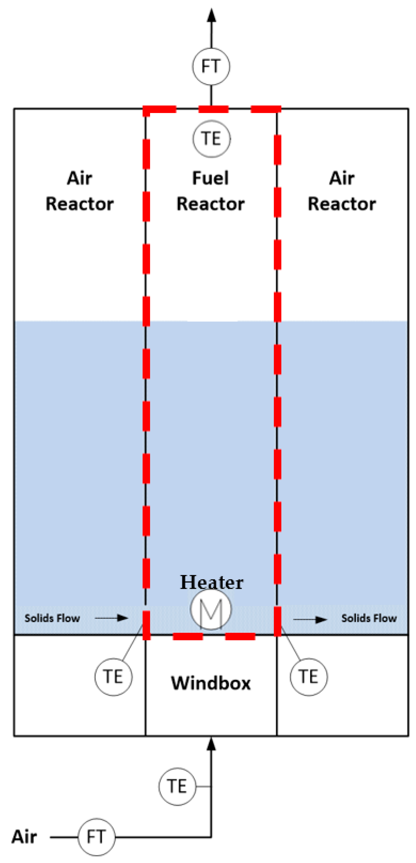
2.1. Experimental Setup of the PFIR Column

The PFIR column (see plan view in Figure 2) consists of an annular vessel separated into two sections, representing the air reactor and fuel reactor in a pressurized chemical looping facility. While chemical looping reactions do not proceed in the PFIR column described in this work, we refer to sections representing the two segments within the column as the air reactor and fuel reactor. The fuel reactor section comprises a 60° slice of the reactor annulus. The relative sizes of the reactor sections are based on the expected volumetric flow rates in the hot reactive flow PCL pilot plant burning natural gas that is under construction at Natural Resources Canada’s CanmetENERGY lab in Ottawa, Canada. The separating walls (henceforth referred to as weirs) have a small, rectangular opening at the bottom to allow solids transfer between sections. The inner process diameter of the PFIR is 0.11 m and the outer process diameter is 0.57 m. The outer wall is clear acrylic, while the inner wall is PVC. The column is 3.87 m tall.
Figure 2 also shows the cold flow system’s important geometric features including tuyere placement, weir locations, purge row locations, and the direction of rotation of the bed material. The distributor plate has a tuyere pitch of 0.056 m and uses angled tuyeres to induce rotational momentum on the bed material. There are 70 tuyeres in the air reactor and 14 tuyeres in the fuel reactor. Of these tuyeres, up to eight of them can be used as purge tuyeres in the air reactor, and up to four of them can be used as purge tuyeres in the fuel reactor. As can be seen, each purge row consists of four tuyeres. The gas flowing through the purge tuyeres was either air or argon. The jet velocity at the exit of the tuyere nozzles was approximately 65 m/s at the base case conditions. When purge gas was introduced, it increased the superficial velocity accordingly.
The bed material used for all tests was brown aluminum oxide with a particle density of 2987 kg/m3 and a Sauter mean particle diameter of 251 μm. This material was selected due to its high density to emulate PCL oxygen carriers. Air was used as the primary fluidizing gas. The PFIR column was operated at near ambient temperature and atmospheric pressure. The windbox of the PFIR column was separated into an air reactor, a fuel reactor, and two purge sections, allowing for different gas compositions and flow rates, as required.
The geometric and operating parameters that were varied can be seen in Table 1. The static bed height was varied from 0.25 m to 0.5 m, with a 0.5 m static bed height as the base case. The weir opening height was varied from 0.05 m to 0.15 m, with a 0.1 m weir opening height as the base case. The purge configuration was varied by changing the number and type of purge rows, as shown in Figure 3. The “no purge row” configuration is the condition where all tuyeres have fluidizing gas flowing through them. The blanked purge row configuration has the row of tuyeres at the interface between reactor sections blocked, effectively removing them, so there is no gas introduced at these locations. The one purge row configuration has one row of angled tuyeres with additional gas flowing through it and is the base case purge configuration. The one vertical purge row configuration is similar to the one purge row configuration, except vertical tuyeres are used instead of angled tuyeres. The fluidization ratio was varied between 2 U/Umf and 4 U/Umf, with a fluidization ratio of 3 U/Umf as the base case. It should be noted that the jet velocity changed with the fluidization ratio since the tuyere nozzle diameter was not changed between conditions. Only one parameter was varied per test condition, with all other parameters held constant at the base case conditions.

2.2. Solid Circulation Rate Measurement Methodology

The solid circulation rate in the PFIR column was determined using a steady-state energy balance considering the boundaries of the fuel reactor as the control volume. A 2800 W in-bed electric heater was located approximately 0.1 m above the distributor plate in the middle of the fuel reactor for solid circulation rate measurements. Type AA resistance temperature detectors (RTDs) measured the gas temperature in the fuel reactor windbox and exiting the fuel reactor. The solids temperatures entering and exiting the fuel reactor were measured at the weir openings at two points along the radius, which were averaged to obtain the average solids temperature entering or exiting the fuel reactor. It was determined that two bed temperature measurements at the inlet and outlet of the fuel reactor section adequately represented the temperature across the weir by varying the number of measurement points prior to the experimental program beginning. An elevation view of the experimental setup for solid circulation rate is shown in Figure 4.
The steady-state energy balance around the fuel reactor is shown in Equation (1).
H e a t   I n g a s + H e a t   I n s o l i d s + H e a t I n h e a t e r = H e a t O u t g a s + H e a t O u t s o l i d s + H e a t O u t [ E n v . L o s s ]
Heat loss to the environment was considered negligible, as it was less than 2% of the heater power at base case conditions. The environmental losses were low, since temperature gradients across the fuel reactor walls were small (less than 30 °C), and the plastic walls have a low thermal conductivity. The solid circulation rate can be calculated by substituting for known quantities and rearranging Equation (1) as shown in Equation (2).
m ˙ s o l i d = m ˙ g a s ,     F R o u t C p , a i r T F R   o u t T r e f m ˙ g a s , F R i n C p , a i r T F R   i n T r e f P H e a t e r C p ,   s o l i d T s o l i d , A R F R T s o l i d , F R A R
where m ˙ solid is the solid circulation rate, m ˙ gas,FRout is the mass flow rate of gas exiting the fuel reactor, m ˙ gas,FRin is the mass flow rate of gas entering the fuel reactor, Cp,air is the heat capacity of the air, Cp,solid is the heat capacity of the oxygen carrier, TFR out is the temperature of the gas exiting the fuel reactor, Tref is the reference temperature, TFR in temperature of the gas entering the fuel reactor, PHeater is the heater power, Tsolid,ARFR is the inlet oxygen carrier temperature, and Tsolid,FRAR is the outlet oxygen carrier temperature. Three assumptions were made: the RTDs in the bed measured the temperature of the solids despite being mostly wetted by the gas, the quantity of solids entering the fuel reactor section was equal to the amount exiting the fuel reactor section, and the mass of air that circulated with the solids was negligible compared to the mass of the solids.

3. Results and Discussion

3.1. Static Bed Height

The static bed height in PCL is an important metric to ensure the desired fuel residence time and thus conversion target is met. Understanding how the static bed height affects the solid circulation rate in a PFIR reactor aids in ensuring the suitability of the PFIR reactor for PCL. Static bed height in the cold flow PFIR column was varied between 0.25 m and 0.5 m. Static bed heights below 0.25 m were not tested, as it is expected that the PFIR will not run with a shallow bed when used for PCL due to the expected reaction kinetics. Further, the solid circulation rate of extremely shallow beds cannot be measured with the current experimental setup due to the location of the in-bed electric heater. Figure 5 shows the effect of static bed height on solid circulation rate. The solid circulation rate was approximately constant across the conditions tested at 3000 kg/h.
Increasing the static bed height should indirectly decrease the solid circulation rate at a constant mass flow rate of air, since the jet velocity will decrease with the associated increase in pressure at the bottom of the bed, decreasing the gas momentum. A simulation of a cold flow PFIR column with slightly different geometry demonstrates this trend, where the bed mass was varied from 59 kg to 1457 kg [33]. This trend is not seen in Figure 5, since the range of bed heights, and hence bed masses, is quite small in comparison. The bed masses in this study were only varied between 66 and 220 kg due to the physical constraints of the system. The gas momentum rate decreased from about 7.1 to 6.7 kg*m/s2 across the range of bed heights tested, which translates to a decrease in solid circulation rate that cannot be measured by the method used here.
Without a sufficiently large change in gas momentum rate, the solid circulation rate is likely to remain fairly constant across the range of bed heights tested since the solids’ rotational momentum will dissipate along bed height as a result of particle–particle interactions [34] that are dependent on operating and geometric parameters of the PFIR column. In the following discussion, we identify the circulation zone to be the portion of the fluidized bed where the solids are actively circulating, i.e., below the point where the solids’ rotational momentum is fully dissipated. All static bed heights tested are likely above this circulation zone, so there is no apparent change in solid circulation rate with static bed height.

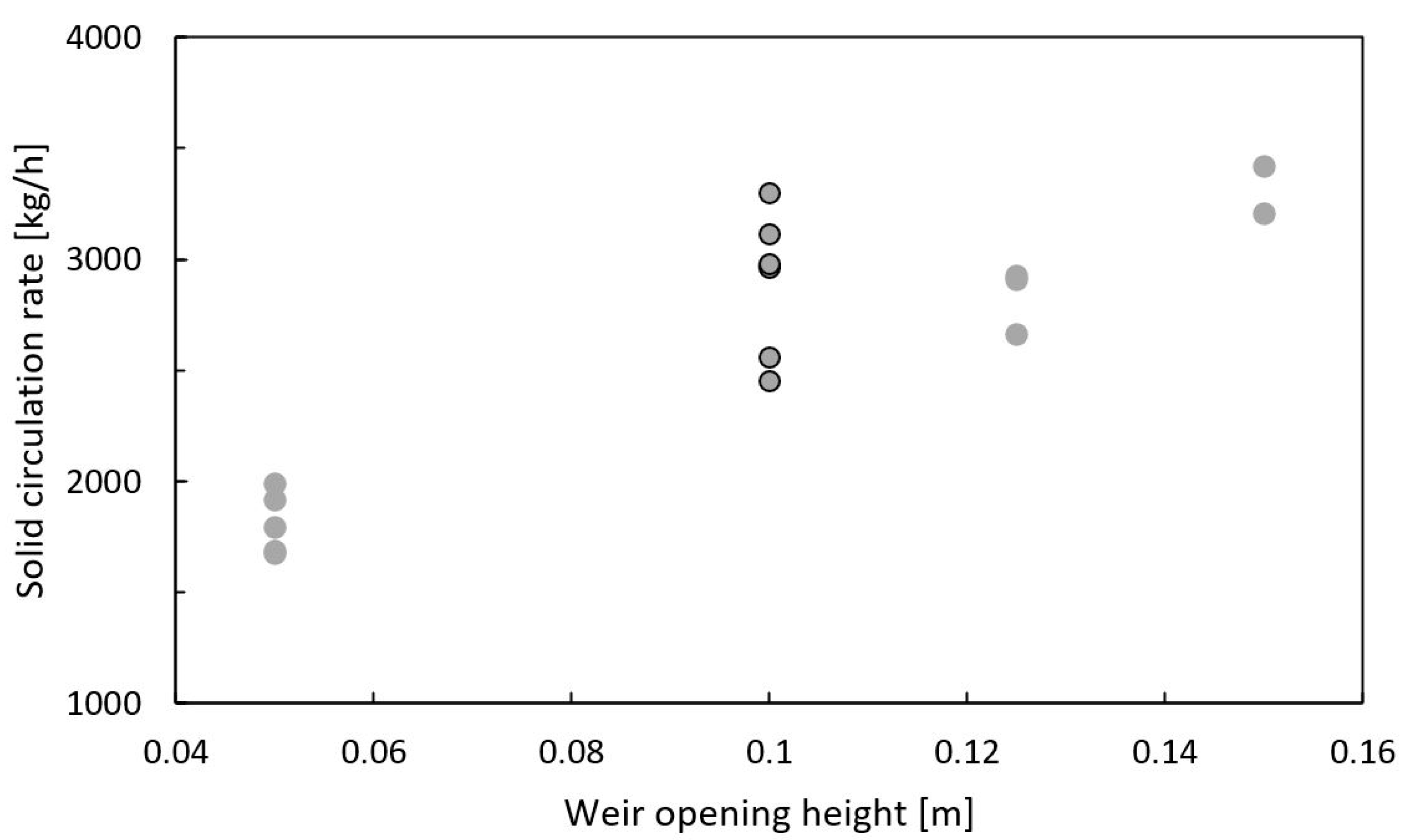
3.2. Weir Opening Height

Increasing the weir opening height increases the available area for solids and gas flow between reactor sections in the PFIR. The effect of weir opening height on solid circulation rate is an important parameter to better understand solids movement in a PFIR reactor and to set the solids circulation rate. The weir opening height was varied between 0.05 m and 0.15 m. Figure 6 shows the solid circulation rate increased from 1800 kg/h to around 3000 kg/h when the weir opening height was increased from 0.05 m to 0.1 m. Increasing the weir opening height further did not have an impact on the solid circulation rate.
The increase in solid circulation rate from a weir opening height of 0.05 m to 0.1 m confirms the presence of a circulation zone, where only the bottom portion of the fluidized bed circulates, and the top portion of the fluidized bed mixes, due to viscous dissipation of the solid momentum. The top of the circulation zone for the PFIR column described herein, at base case conditions, is thus somewhere between 0.05 m to 0.1 m. The circulation zone was also evident in a simulation of the PFIR reactor for biomass pyrolysis, where the mass flux of solids decreases to almost zero at 0.18 m above the distributor for the operating conditions and geometry of the PFIR simulated [35]. The presence of the weir within or near the circulation zone may also affect the flow pattern near the weir openings, inducing eddies near the weir, similar to what is seen with gated spillways [36].

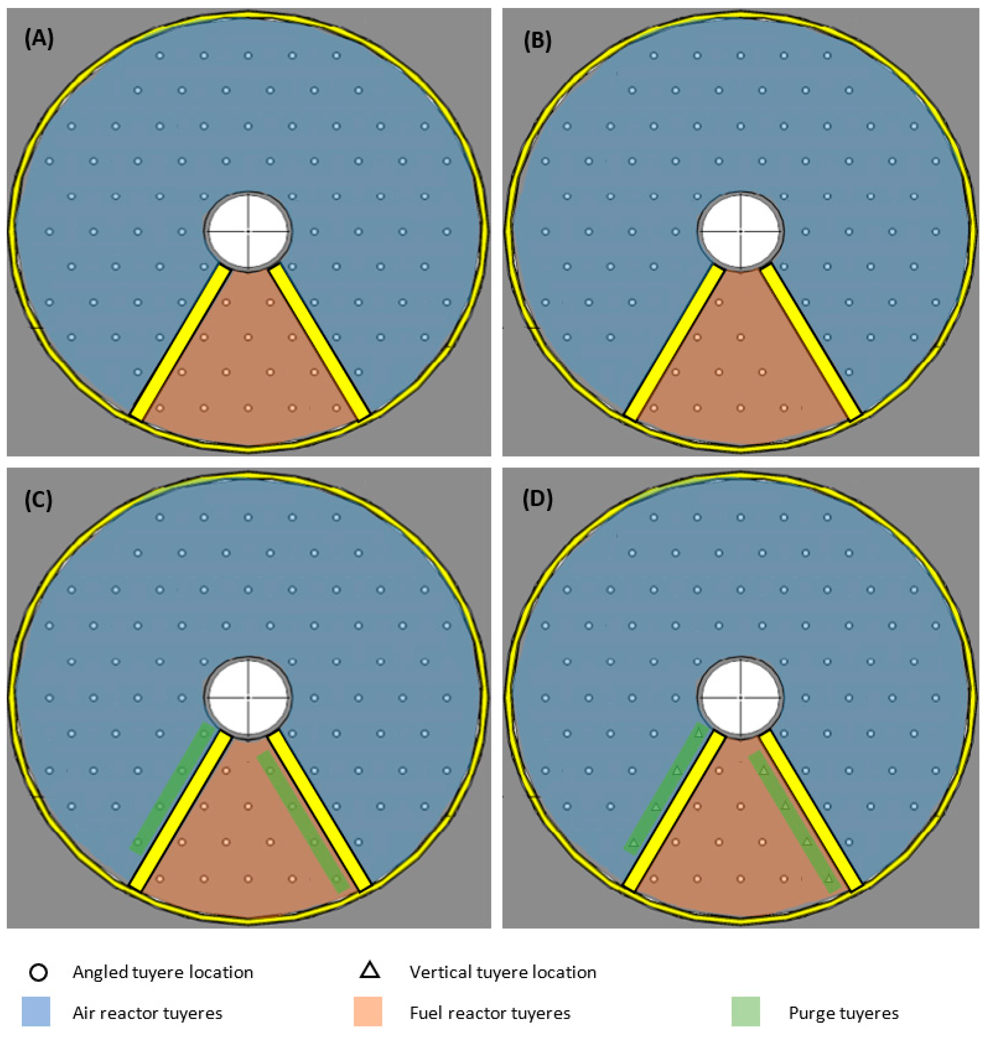
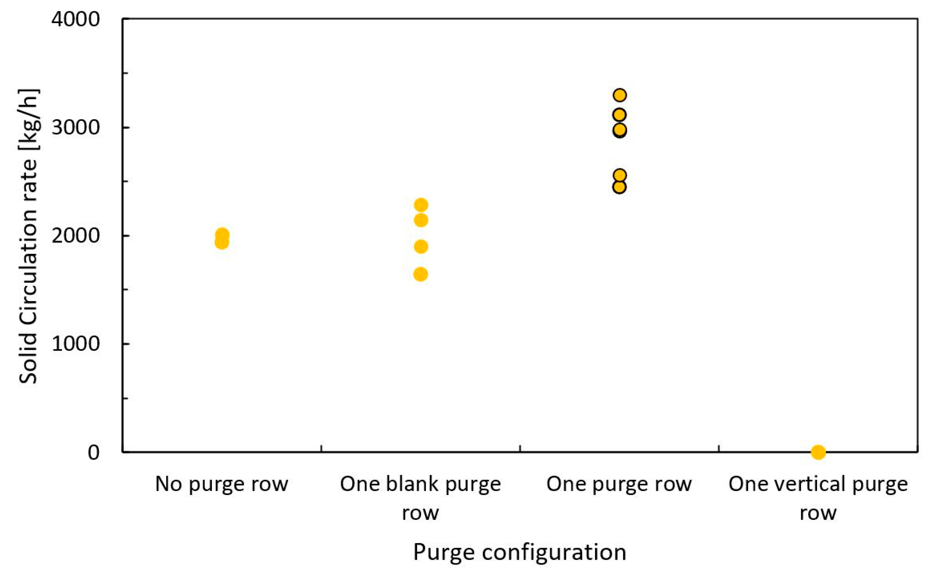
3.3. Purge Configuration

The amount of gas flowing, or leaking, between the air reactor section and the fuel reactor section, can affect the extent of downstream purification of the CO2 stream and/or the amount of CO2 that is released into the atmosphere. One method to limit the gas leakage between reactor sections is to use a purge gas, such as steam, at the interface between the reactor sections. Though the configuration of the purge gas section of the PFIR reactor will have a large impact on gas leakage, it also influences the solid circulation rate and will help inform the purge configuration that minimizes gas leakage, while achieving the required solid circulation rate.
Four purge section configurations were investigated: no purge, a blank row where no gas is flowing, one angled purge row, and one vertical purge row. All purge tuyeres had approximately the same jet velocity of 65 m/s. Figure 7 shows the effect of the purge configuration on the solid circulation rate. The two configurations with no purging have a solid circulation rate of about 2000 kg/h. The solid circulation rate increased to 3000 kg/h when one row of angled purge jets was used. However, when one row of vertical jets is used, the solid circulation completely stops.
An increase in solid circulation rate from the no purge row and one blank purge row configuration to the one purge row configuration likely is due to an overall increase in gas momentum in the fluidized bed due to the addition of the purge gas. The solid circulation rate increased by 46%, while the momentum increased by 15%, indicating that the gas momentum strongly influences the solid circulation rate.
Despite the one blank purge row configuration having no angled gas flow directly in front of the weir opening to push the solids into the adjacent section, the solid circulation rate remained the same. Solids movement despite no additional gas flow from below is a phenomenon observed elsewhere; pyroclastic flows are fast-moving solids that flow along the ground from a volcanic eruption, without an additional input of gas. A layer of stagnant solids remains close to the ground, while solids near the top leading edge of the pyroclastic flow fall toward the ground and become stagnant [37]. This allows for the pyroclastic flow to continue for a great distance. A similar phenomenon may be occurring at the blanked purge tuyeres, where the local area becomes defluidized but does not prevent movement, as only a thin layer of solids remains stagnant near the distributor plate, while the rest of the solids stay in motion. This defluidization, while maintaining solid circulation, may lower gas leakage between reactor sections if the dominant mechanism of gas leakage is through the lean phase (i.e., jets and bubbles), rather than the dense phase. This concept will be considered in future work.
The one vertical purge row configuration caused all solid circulation to stop. The purge gas acted similarly to an air curtain, preventing the flow of solids between reactor sections due to the change in direction of solids directly before the weir opening. This result further demonstrates that fluid flow patterns near the weir opening have an impact on solids flow patterns, and thus solid circulation rate. There is likely a lower gas flow rate that would allow for a solid circulation rate with the vertical purge configuration, but determining this flow rate was not evaluated in this study.

3.4. Fluidization Ratio/Jet Velocity

Control of the air flow rate is expected to play an important role in regulating the solid circulation since the gas momentum from the jets imparts rotational momentum to the solids. Air flow rates at three fluidization ratios were tested: 2 U/Umf, 3 U/Umf, and 4 U/Umf. It should be noted that the tuyere diameters were not changed, so the jet velocity also increased as the fluidization ratio increased. Due to the temperature limitations of the experimental equipment, the solid circulation rate could not be determined for fluidization ratios below 2 U/Umf. This limitation poses no issue, as this PCL configuration is not expected to operate below 2 U/Umf. Figure 8 shows that the solid circulation rate increases linearly from 1400 kg/h to 4800 kg/h with increasing fluidization ratio over the range tested.
An increase in solid circulation with increasing fluidization ratio is expected, since there is both an increase in mass flow rate and jet velocity of the air, which both increase the gas momentum. The total gas momentum rate increases from about 3.2 to 12.3 kg*m/s2 with an increase in fluidization ratio from 2 U/Umf to 4 U/Umf. This larger increase in total gas momentum translates to a large increase in solid rotational momentum and solid circulation rate.

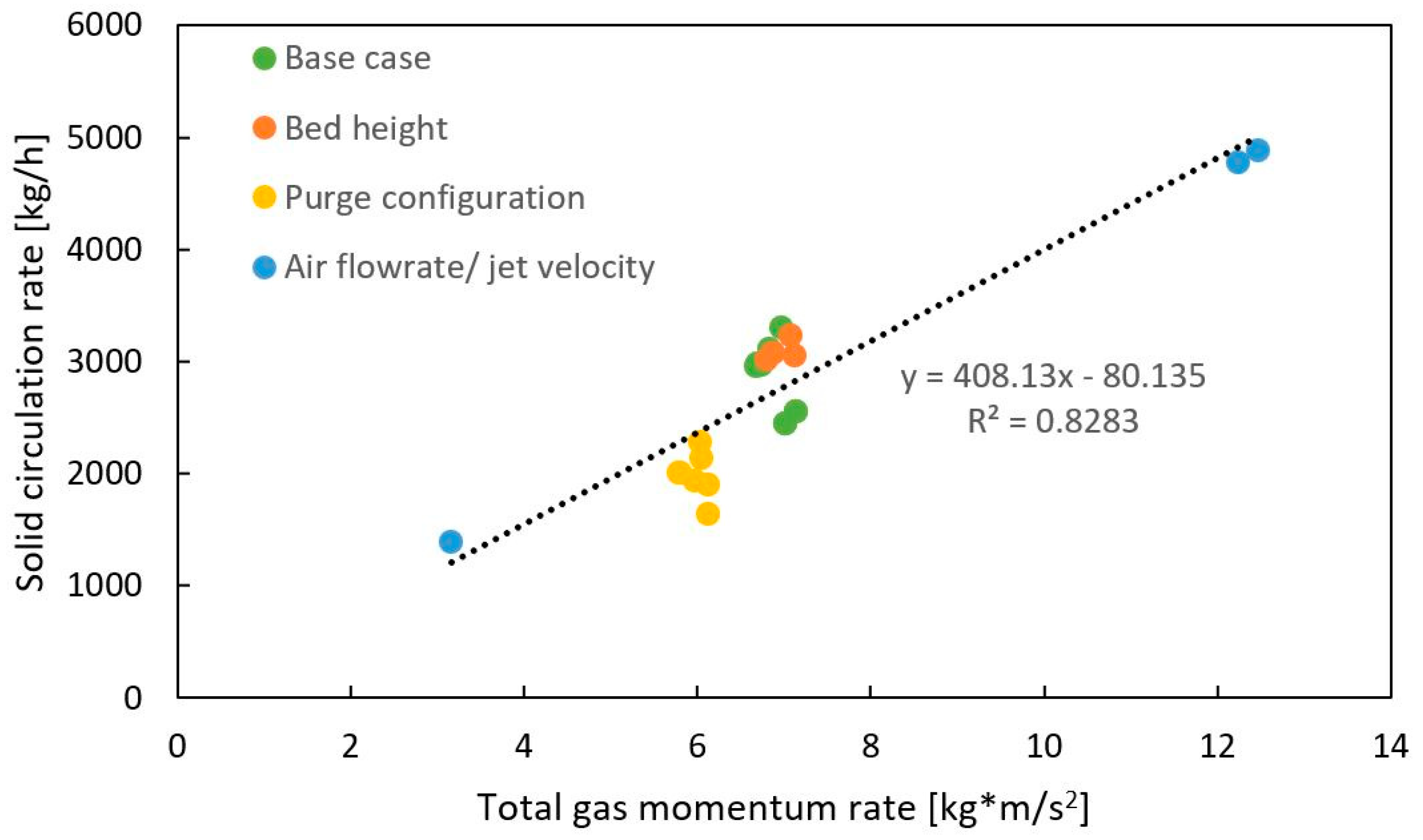
3.5. Relationship between Solid Circulation Rate and Total Gas Momentum

The main driver for the solid circulation rate is the total gas momentum, shown in Figure 9. The solid circulation rate increases linearly with the gas momentum rate across all conditions where there was no resistance to flow imparted by the weir or vertical jets. Changing the fluidization ratio has the biggest impact on the solid circulation rate since it has the largest impact on total gas momentum. The purge configuration does have an impact on the gas momentum as the removal of a purge row means less gas is introduced into the bed, thus the total gas momentum decreases compared to the base case.
Figure 10 shows that when restrictions to solids flow are introduced, such as the weir itself or vertical jets, the solid circulation rate generally decreases without a change in the total gas momentum rate. The exception to this is when the restriction is outside of the circulation zone, such as conditions where the weir opening heights were at or above 0.1 m. Restrictions above the circulation zone appear to have no impact on the circulation of solids. Restrictions to solids flow near the weir openings impact the solid circulation rate and should be considered when choosing the exact PFIR reactor geometry.

4. Conclusions

The oxygen carrier circulation rate was evaluated in a novel cold flow chemical looping reactor. The PFIR offers a compact dual fluidized bed reactor that may provide a reasonable solution for carbon capture of small- to medium-scale emitters. The circulation rate of oxygen carrier is a key performance indicator for any reactor design for PCL since it must be sufficiently high to achieve the required fuel conversion, oxygen transport, and sufficient heat exchange between reactors. Solid circulation rates ranged from 0 kg/h up to 4800 kg/h at the conditions tested. These results demonstrate that sufficiently high solid circulation rates can be achieved, but certain methods can be used to decrease the solid circulation rate if required. Across all conditions tested, it was determined that parameters that affect the total gas momentum the most have the largest impact on solid circulation rate, such as the fluidization ratio. Configurations where solids flow was restricted, inducing different flow patterns near the weir within the circulation zone, such as the weir itself or vertical purges, led to a decrease in solid circulation rate despite the gas momentum remaining constant. It is likely that the flow patterns near the weir dictate the solid circulation rate for a given total gas momentum.
The research and development of the PFIR reactor for PCL lends itself to several areas of future work. Firstly, the gas leakage between reactor sections must be studied to ensure that CO2 purity and emission targets can be achieved. Understanding which parameters affect gas leakage will help determine how gas leakage is primarily occurring, i.e., with the lean or dense phase. A second avenue of future work is to validate the CPFD model of the PFIR reactor. Once validated, the model can be used to better understand mechanistic information related to solids and gas movement within the reactor. Finally, a reacting flow PCL pilot plant using a PFIR reactor will be studied to ensure the feasibility of using a PFIR reactor for PCL.

Author Contributions

Conceptualization, A.E.A., N.K.B., S.C. and R.W.H.; methodology, A.E.A., N.K.B., S.C., R.W.H. and A.M.; validation, A.E.A.; formal analysis, A.E.A.; investigation, A.E.A.; data curation, A.E.A.; writing—original draft preparation, A.E.A.; writing—review and editing, N.K.B., S.C., R.W.H. and A.M.; visualization, A.E.A.; supervision, S.C., R.W.H. and A.M.; project administration, S.C. and R.W.H.; funding acquisition, S.C. and R.W.H. All authors have read and agreed to the published version of the manuscript.

Funding

This research was funded by the Program for Energy Research and Development (PERD) at Natural Resources Canada, Government of Canada.

Data Availability Statement

Data are contained within the article.

Acknowledgments

The authors would like to thank Hatch for their collaboration on the development and commercialization of PCL, including CPFD modeling, and on the chemical looping reactor design used in this work, which is based upon their patent for a plug flow with internal recirculation reactor.

Conflicts of Interest

The authors declare no conflicts of interest.

References

  1. Environment and Climate Change Canada Greenhouse Gas Reporting Program (GHGRP)—Facility Greenhouse Gas (GHG) Data. 2018. Available online: https://open.canada.ca/data/en/dataset/a8ba14b7-7f23-462a-bdbb-83b0ef629823 (accessed on 19 April 2023).
  2. Panja, P.; McPherson, B.; Deo, M. Techno-Economic Analysis of Amine-Based CO2 Capture Technology: Hunter Plant Case Study. Carbon Capture Sci. Technol. 2022, 3, 100041–100049. [Google Scholar] [CrossRef]
  3. Symonds, R.T.; Hughes, R.W.; De Las Obras Loscertales, M. Oxy-Pressurized Fluidized Bed Combustion: Configuration and Options Analysis. Appl. Energy 2020, 262, 114531. [Google Scholar] [CrossRef]
  4. Zhao, J.; Ma, L.; Zayed, M.E.; Elsheikh, A.H.; Li, W.; Yan, Q.; Wang, J. Industrial Reheating Furnaces: A Review of Energy Efficiency Assessments, Waste Heat Recovery Potentials, Heating Process Characteristics and Perspectives for Steel Industry. Process Saf. Environ. Prot. 2021, 147, 1209–1228. [Google Scholar] [CrossRef]
  5. Yun, S.; Lee, J.; Cho, H.; Kim, J. Oxy-Fuel Combustion-Based Blue Hydrogen Production with the Integration of Water Electrolysis. Energy Convers. Manag. 2023, 291, 117275. [Google Scholar] [CrossRef]
  6. Zanco, S.E.; Pérez-Calvo, J.-F.; Gasós, A.; Cordiano, B.; Becattini, V.; Mazzotti, M. Postcombustion CO2 Capture: A Comparative Techno-Economic Assessment of Three Technologies Using a Solvent, an Adsorbent, and a Membrane. ACS Eng. Au 2021, 1, 50–72. [Google Scholar] [CrossRef]
  7. Lyngfelt, A. Oxygen Carriers for Chemical-Looping Combustion. In Calcium and Chemical Looping Technology for Power Generation and Carbon Dioxide (CO2) Capture; Fennell, P., Anthony, B., Eds.; Elsevier: Sawston, UK, 2015; pp. 221–254. ISBN 978-0-85709-243-4. [Google Scholar]
  8. Daneshmand-Jahromi, S.; Sedghkerdar, M.H.; Mahinpey, N. A Review of Chemical Looping Combustion Technology: Fundamentals, and Development of Natural, Industrial Waste, and Synthetic Oxygen Carriers. Fuel 2023, 341, 127626. [Google Scholar] [CrossRef]
  9. Abuelgasim, S.; Wang, W.; Abdalazeez, A. A Brief Review for Chemical Looping Combustion as a Promising CO2 Capture Technology: Fundamentals and Progress. Sci. Total Environ. 2021, 764, 142892. [Google Scholar] [CrossRef] [PubMed]
  10. Pröll, T. Fundamentals of Chemical Looping Combustion and Introduction to CLC Reactor Design. In Calcium and Chemical Looping Technology for Power Generation and Carbon Dioxide (CO2) Capture; Fennell, P., Anthony, B., Eds.; Elsevier: Sawston, UK, 2015; pp. 197–219. ISBN 978-0-85709-243-4. [Google Scholar]
  11. Mission Innovation. Report of the Mission Innovation Carbon Capture, Utilization, and Storage Experts’ Workshop; Accelerating Breakthrough Innovation in Carbon Capture, Utilization, and Storage: Houston, TX, USA, 2017; pp. 1–291. [Google Scholar]
  12. Czakiert, T.; Krzywanski, J.; Zylka, A.; Nowak, W. Chemical Looping Combustion: A Brief Overview. Energies 2022, 15, 1563. [Google Scholar] [CrossRef]
  13. Di Giuliano, A.; Capone, S.; Anatone, M.; Gallucci, K. Chemical Looping Combustion and Gasification: A Review and a Focus on European Research Projects. Ind. Eng. Chem. Res. 2022, 61, 14403–14432. [Google Scholar] [CrossRef]
  14. Son, S.R.; Kim, S.D. Chemical-Looping Combustion with NiO and Fe2O3 in a Thermobalance and Circulating Fluidized Bed Reactor with Double Loops. Ind. Eng. Chem. Res. 2006, 45, 2689–2696. [Google Scholar] [CrossRef]
  15. Rydén, M.; Moldenhauer, P.; Mattisson, T.; Lyngfelt, A.; Younes, M.; Niass, T.; Fadhel, B.; Ballaguet, J.-P. Chemical-Looping Combustion with Liquid Fuels. Energy Procedia. 2013, 37, 654–661. [Google Scholar] [CrossRef]
  16. Moldenhauer, P.; Linderholm, C.; Rydén, M.; Lyngfelt, A. Avoiding CO2 Capture Effort and Cost for Negative CO2 Emissions Using Industrial Waste in Chemical-Looping Combustion/Gasification of Biomass. Mitig. Adapt. Strateg. Glob. Chang. 2020, 25, 1–24. [Google Scholar] [CrossRef]
  17. Chen, C.; Chen, C.-H.; Chang, M.-H.; Lee, H.-H.; Chang, Y.-C.; Wen, T.-W.; Shen, C.-H.; Wan, H.-P. A 30-kWth Moving-Bed Chemical Looping System for Hydrogen Production. Int. J. Greenh. Gas. Control 2020, 95, 102954–102960. [Google Scholar] [CrossRef]
  18. Zhang, Q.; Joshi, R.K.; Xu, D.; Tong, A.; Fan, L.-S. A Novel Moving Bed Chemical Looping Process with Integration of Combustor Heat Exchangers for Hydrogen Production: Process Simulation and Techno-Economic Analysis. Int. J. Hydrogen Energy 2024, 49, 823–839. [Google Scholar] [CrossRef]
  19. Noorman, S.; van Sint Annaland, M. Kuipers Packed Bed Reactor Technology for Chemical-Looping Combustion. Ind. Eng. Chem. Res. 2007, 46, 4212–4220. [Google Scholar] [CrossRef]
  20. Abanades, J.C.; Diego, M.E.; Fernández, J.R. A Novel Air Reactor Concept for Chemical Looping Combustion Systems Operated at High Pressure. Chem. Eng. J 2020, 390, 124507. [Google Scholar] [CrossRef]
  21. Diego, M.E.; Abanades, J.C. Experimental Investigation of a Diffusion-Controlled Chemical Looping Air Reactor for Energy Storage Applications. Chem. Eng. J. 2022, 428, 132083–132091. [Google Scholar] [CrossRef]
  22. Dahl, I.M.; Bakken, E.; Larring, Y.; Spjelkavik, A.I.; Håkonsen, S.F.; Blom, R. On the Development of Novel Reactor Concepts for Chemical Looping Combustion. Energy Procedia. 2009, 1, 1513–1519. [Google Scholar] [CrossRef]
  23. Håkonsen, S.F.; Blom, R. Chemical Looping Combustion in a Rotating Bed Reactor—Finding Optimal Process Conditions for Prototype Reactor. Environ. Sci. Technol. 2011, 45, 9619–9626. [Google Scholar] [CrossRef]
  24. Adham, K.; Harris, C.T.; Kokourine, A. Plug Flow Reactor with Internal Recirculation Fluidized Bed. 2017. CA 2951724 C, 8 May 2015. [Google Scholar]
  25. Alain, A.; Bond, N.; Champagne, S.; McIntyre, C.; Francey, S.; Macchi, A.; Hughes, R. Impact of Gas Distributor on Hydrodynamics in a Cold Flow Annular Dual Fluidized Bed for Pressurized Chemical Looping. In Proceedings of the Fluidized Bed Conversion Conference 2022, Gothenburg, Sweden, 8–11 May 2022; pp. 1–9. [Google Scholar]
  26. Riley, J.; Siriwardane, R.; Poston, J. Bench Scale Analysis of the Physical Attrition Properties for Copper-Ferri-Aluminate Oxygen Carriers during Chemical Looping Combustion. Powder Technol. 2020, 366, 891–905. [Google Scholar] [CrossRef]
  27. Reppenhagen, J.; Werther, J. Catalyst Attrition in Cyclones. Powder Technol. 2000, 113, 55–69. [Google Scholar] [CrossRef]
  28. Werther, J.; Reppenhagen, J. Catalyst Attrition in Fluidized-Bed Systems. AIChE J. 1999, 45, 2001–2010. [Google Scholar] [CrossRef]
  29. Kramp, M.; Thon, A.; Hartge, E.-U.; Heinrich, S.; Werther, J. The Role of Attrition and Solids Recovery in a Chemical Looping Combustion Process. Oil Gas Sci. Technol. 2011, 66, 277–290. [Google Scholar] [CrossRef]
  30. Grochowalski, J.; Widuch, A.; Sładek, S.; Melka, B.; Nowak, M.; Klimanek, A.; Andrzejczyk, M.; Klajny, M.; Czarnowska, L.; Hernik, B.; et al. Technique for Reducing Erosion in Large-Scale Circulating Fluidized Bed Units. Powder Technol. 2023, 426, 118651–118666. [Google Scholar] [CrossRef]
  31. Wang, Q.; Luo, Z.; Fang, M.; Ni, M.; Cen, K. Development of a New External Heat Exchanger for a Circulating Fluidized Bed Boiler. Chem. Eng. Process 2003, 42, 327–335. [Google Scholar] [CrossRef]
  32. Bai, R.; Zhou, T.; Zhang, M.; Zhu, S.; Yang, H. Time-Scaled Study on the Erosion in Circulating Fluidized Bed Based on CPFD Method. Powder Technol. 2023, 430, 118830–118839. [Google Scholar] [CrossRef]
  33. McIntyre, C. CPFD Modeling of a Novel Internally Circulating Bubbling Fluidized Bed for Chemical Looping Combustion; Université d’Ottawa/University of Ottawa: Ottawa, ON, Canada, 2021. [Google Scholar]
  34. Patil, D.J.; Van Sint Annaland, M.; Kuipers, J.A.M. Critical Comparison of Hydrodynamic Models for Gas–Solid Fluidized Beds—Part I: Bubbling Gas–Solid Fluidized Beds Operated with a Jet. Chem. Eng. Sci. 2005, 60, 57–72. [Google Scholar] [CrossRef]
  35. Adham, K.; Harris, C.; Kokourine, A. Modeling and Process Features of Plug Flow Reactor with Internal Recirculation for Biomass Pyrolysis. J. Chem. Eng. Process Technol. 2017, 08, 1000353–1000358. [Google Scholar] [CrossRef]
  36. South Florida Water Management District. Atlas of Flow Computations at District Hydraulic Structures in the South Florida Water Management District. Available online: https://www.sfwmd.gov/sites/default/files/documents/atlas_of_flow_computation_at_sfwmd_hydraulic_structures.pdf (accessed on 24 November 2023).
  37. Salatino, P.; Marzocchella, A.; Bareschino, P. Fluidization in Nature: Pyroclastic Flows. In Proceedings of the Presented at the Fluidization XVII Conference, Edinburgh, Scotland, 21–25 May 2023. [Google Scholar]
Figure 1. Simplified diagram of the plug flow with internal recirculation (PFIR) reactor, showing (A) the plan view, (B) elevation at one of the weirs, and (C) 3D view [25].
Energies 17 00198 g001
Figure 2. Annotated diagram showing the plan view of the cold flow PFIR tuyere plate with important measurements.
Energies 17 00198 g002
Figure 3. Diagrams of purge tuyere configurations: (A) no purge row configuration, (B) blanked purge row configuration, (C) one purge row configuration, (D) one vertical purge row configuration.
Energies 17 00198 g003
Figure 4. Experimental concept for quantifying solid circulation rate. FT indicates the location of flowmeters and TE indicates the location of the type AA RTDs. The control volume for the energy balance is indicated by the red box.
Energies 17 00198 g004
Figure 5. The effect of static bed height on solid circulation rate. The data points with a black outline indicate the base case.
Energies 17 00198 g005
Figure 6. The effect of weir opening height on solid circulation rate. The base case is indicated by the data points with a black outline.
Energies 17 00198 g006
Figure 7. The effect of purge configuration on solid circulation rate. The base case is indicated by the data points with a black outline.
Energies 17 00198 g007
Figure 8. The effect of fluidization ratio on solid circulation rate. The base case is indicated by the data points with a black outline.
Energies 17 00198 g008
Figure 9. Relationship between gas momentum rate and solid circulation rate. Only conditions where there was no resistance to flow are shown.
Energies 17 00198 g009
Figure 10. Flow restrictions within the circulation zone of the PFIR column decrease the solid circulation rate at a constant total gas momentum rate.
Energies 17 00198 g010
Table 1. Overview of varied geometric and operating parameters.
ParameterValue/ConfigurationBase Case
Static bed height0.25 m, 0.35 m, 0.5 m0.5 m
Weir opening height0.05 m, 0.1 m, 0.125 m, 0.15 m0.1 m
Purge configuration No purge row
Blanked purge row
One purge row
One vertical purge row
One purge row
Fluidization ratio [jet velocity]2 U/Umf [43 m/s], 3 U/Umf [65 m/s], 4 U/Umf [86 m/s]3 U/Umf [65 m/s]
Disclaimer/Publisher’s Note: The statements, opinions and data contained in all publications are solely those of the individual author(s) and contributor(s) and not of MDPI and/or the editor(s). MDPI and/or the editor(s) disclaim responsibility for any injury to people or property resulting from any ideas, methods, instructions or products referred to in the content.

