Abstract
Carbon capture and storage (CCS) is a critical technology for mitigating greenhouse gas emissions and combating climate change. CCS involves capturing CO2 emissions from industrial processes and power plants and injecting them deep underground for long-term storage. The success of CCS projects is influenced by various factors, including the regional pressure dissipation effects in subsurface geological formations. The safe and efficient operation of CCS projects depends on maintaining the pressure in the storage formation. Regional pressure dissipation, often resulting from the permeability and geomechanical properties of the storage site, can have significant effects on project integrity. This paper provides a state-of-art of the impact of regional pressure dissipation on CCS projects, highlights its effects, and discusses ongoing investigations in this area based on different case studies. The results corroborate the idea that the Sleipner project has considerable lateral hydraulic connectivity, which is evidenced by pressure increase ranging from <0.1 MPa in case of an uncompartmentalized reservoir to >1 MPa in case of substantial flow barriers. After five years of injection, pore pressures in the water leg of a gas reservoir have increased from 18 MPa to 30 MPa at Salah project, resulting in a 2 cm surface uplift. Furthermore, artificial CO2 injection was simulated numerically for 30 years timespan in the depleted oil reservoir of Jurong, located near the Huangqiao CO2-oil reservoir. The maximum amount of CO2 injected into a single well could reach 5.43 × 10⁶ tons, potentially increasing the formation pressure by up to 9.5 MPa. In conclusion, regional pressure dissipation is a critical factor in the implementation of CCS projects. Its impact can affect project safety, efficiency, and environmental sustainability. Ongoing research and investigations are essential to improve our understanding of this phenomenon and develop strategies to mitigate its effects, ultimately advancing the success of CCS as a climate change mitigation solution.
1. Introduction
The 21st century presents an unprecedented set of challenges for humanity, with climate change standing out as one of the most pressing issues. The accumulation of greenhouse gases in the earth’s atmosphere, primarily carbon dioxide (CO2), has led to detrimental changes in global climate patterns, resulting in more frequent and severe weather events, rising sea levels, and disruptions to ecosystems and biodiversity. To mitigate the adverse effects of climate change, there is a critical need to reduce CO2 emissions and transition towards cleaner energy sources. In this context, carbon capture and storage (CCS) has emerged as a promising technology with the potential to significantly contribute to greenhouse gas reduction efforts.
Furthermore, as global energy demand continues to rise, traditional fossil fuels remain a primary source of energy, leading to persistent CO2 emissions [1]. While renewable energy sources are being rapidly developed, their complete integration into the energy mix is a gradual process [2]. In the interim, CCS presents a viable strategy to bridge the gap between current energy consumption patterns and a low-carbon future. By capturing CO2 emissions at their source, CCS can substantially reduce emissions from industrial sectors such as power generation, cement production, and steel manufacturing [3,4,5,6]. CCS involves capturing CO2 emissions from industrial processes and power plants, transporting the captured CO2 to suitable geological formations, and injecting it deep underground for long-term storage [7], as shown in Figure 1. During the capture phase, CO2 is separated from flue gases produced by industrial facilities or power plants [8,9]. The captured CO2 is then compressed and transported via pipelines or other means to geological storage sites [10]. In addition, geologic CO2 utilization and storage (GCUS) stands out as a leading solution, leveraging current technologies to significantly mitigate CO2 emissions into the atmosphere. GCUS involves the containment of captured CO2 from emission sources underground for extended periods, spanning hundreds to thousands of years [11]. These storage sites are typically deep geological formations, such as depleted oil and gas reservoirs, saline aquifers, or deep coal seams [12]. Deep saline aquifers exhibit the highest CO2 storage capacity among various CO2 injection formations. In China, deep saline aquifers are estimated to hold 1573 gigatons of CO2, with a 50% confidence level [13]. This capacity equals approximately 130 years of China’s total CO2 emissions. In North America, a conservative estimate places the total CO2 storage capacity of deep saline aquifers at 2379 gigatons, equivalent to around 600 years of North America’s total CO2 emissions. Despite the adoption of alternative energy sources, global carbon capture, utilization, and storage (GCUS) technologies must be universally implemented, emphasizing the imperative of their deployment alongside clean and efficient energy solutions. Once injected into these formations, the CO2 is intended to be trapped and stored for extended periods, contributing to a reduction in atmospheric CO2 concentrations [14]. This process prevents a substantial amount of CO2 from entering the atmosphere and exacerbates the global climate crisis. While CCS holds great promise, its widespread adoption demands rigorous investigation into its potential impacts on various geological, environmental, and operational aspects. Of particular concern is the regional pressure dissipation impact resulting from the injection and storage of large volumes of CO2 in geological formations [15].
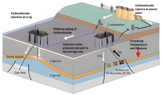
Figure 1.
Process of sequestering CO2 in deep saline aquifers [16]. Reproduced with permission from [16], Elsevier, 2012.
Regional pressure dissipation refers to the spread and redistribution of pore pressure changes induced by the injection of fluids into subsurface formations [17]. When CO2 is injected into a reservoir, it displaces existing fluids and increases the overall pore pressure within the reservoir. This rise in pressure occurs because the injected CO2 occupies pore spaces that were previously filled with other fluids, such as brine or hydrocarbons [18]. Consequently, understanding how this increased pore pressure propagates through the subsurface and interacts with surrounding rocks and fluids is crucial for assessing the long-term viability and safety of CO2 injection projects [19,20].
The viability of CCS extends beyond emission reduction; it also facilitates the concept of “negative emissions”, wherein more CO2 is removed from the atmosphere than is emitted [21]. This is achieved through the combination of CCS with bioenergy, where plants absorb CO2 from the atmosphere during growth, and the resulting biomass is burned for energy with the CO2 emissions being captured and stored underground in the geological formations [22], as shown in Figure 2. Such an approach could potentially contribute to drawing down historical CO2 emissions, aiding in achieving the ambitious climate targets outlined in international agreements like the Paris Agreement which is a legally binding international treaty on climate change.
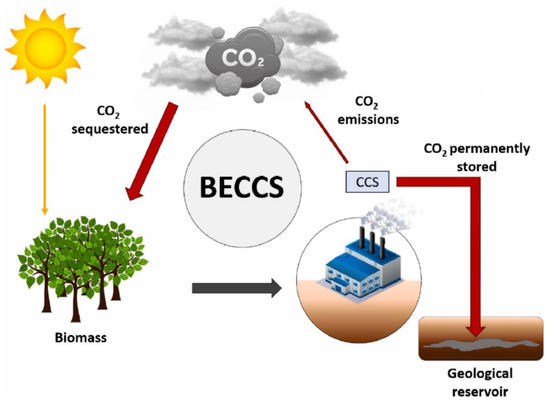
Figure 2.
The utilization of bioenergy with CCS systems results in the establishment of a carbon flow that moves from the atmosphere into storage in a negative direction [22].
The process of injecting CO2 into geological formations for storage involves a high-pressure injection to ensure that the CO2 remains in a supercritical state, enhancing its density and reducing the risk of buoyant migration [23]. However, the injection of CO2 at high pressures can lead to significant pressure changes within the targeted storage formations over time. These pressure changes can have a range of effects that need to be thoroughly investigated to ensure the safe and effective implementation of CCS projects [24,25]. One of the primary concerns associated with pressure changes is the potential for induced seismicity [26]. The injection of fluids, including CO2, into subsurface formations can alter the stress distribution within the earth’s crust, potentially triggering earthquakes [27]. Understanding the relationship between pressure changes and induced seismicity is crucial for assessing the risk of seismic events and establishing safe injection practices [28,29,30]. Pressure changes can also influence the stability of the caprock—the impermeable layer of rock that seals the storage formation [31]. Changes in pressure can potentially impact the integrity of the caprock, leading to the creation of new pathways for CO2 migration or even surface leakage. Investigating the mechanical behaviour of the caprock under pressure changes is paramount to preventing unintended consequences [32].
Moreover, subsurface pressure changes can result in ground deformation, either uplift or subsidence. Such deformations can have far-reaching environmental and societal implications, including potential damage to infrastructure, altered groundwater flow patterns, and disruptions to ecosystems [33,34,35]. A comprehensive understanding of pressure-induced ground movements is crucial for effective planning, risk assessment, and the design of CCS projects. Therefore, effectively managing pressure within CO2 storage sites is a crucial aspect of safe and successful CCS implementation. The investigation will explore various operational strategies aimed at mitigating pressure build-up and dissipation. This includes examining optimal injection rates, pressure monitoring protocols, and the feasibility of implementing pressure management wells. Engineering solutions for pressure control, such as pressure release mechanisms and adaptive reservoir management, will also be investigated to provide practical insights for CCS project design and operation.
The investigation into the regional pressure dissipation impact of CCS requires a multidisciplinary approach that integrates geological, geomechanical, hydrogeological, and environmental perspectives [36,37]. The geological characteristics of the storage formation, such as porosity and permeability, play a significant role in determining how pressure changes propagate through the subsurface [38]. Geomechanical considerations are vital for understanding how pressure changes influence the mechanical behaviour of rock formations and caprock [39]. Therefore, hydrogeological studies are essential for comprehending the interactions between the injected CO2, existing fluids, and storage formation. These interactions can impact fluid flow patterns, alter the chemical composition of the fluids, and influence the overall pressure dynamics [40,41]. Moreover, an in-depth understanding of environmental factors is required to evaluate the potential consequences of pressure-induced ground movements on ecosystems, infrastructure, and land use [42,43].
To comprehensively investigate the regional pressure dissipation impact of CCS, a combination of theoretical, numerical, and experimental approaches is essential. Analytical models can provide fundamental insights into the processes governing pressure changes, allowing for the formulation of hypotheses and guiding the development of numerical simulations [44,45]. Numerical models, such as computational fluid dynamics simulations and geomechanical models, offer the capability to simulate complex interactions in realistic geological settings [46,47,48]. Laboratory experiments using rock samples and scaled models can validate the theoretical and numerical findings, offering empirical data that enhances the accuracy and reliability of the investigation’s outcomes [49,50]. Field studies that monitor ongoing CCS operations and their pressure-related effects provide real-world data that can be used to refine and validate theoretical and numerical models [51,52].
The investigation into the regional pressure dissipation impact of CCS holds significant importance for the successful deployment of this technology on a global scale. As governments, industries, and international organizations increasingly recognize the urgency of addressing climate change, the responsible deployment of CCS becomes integral to achieving emission reduction targets. This comprehensive study aims to delve into the intricate web of effects and implications surrounding the regional pressure dissipation phenomenon resulting from CCS activities.
2. Mechanism of Regional Pressure Dissipation
The injection of CO2 into geological formations is a central strategy in addressing the challenges of global climate change. This approach aims to sequester large amounts of CO2 in deep underground reservoirs, effectively preventing its release into the atmosphere and mitigating the impacts of greenhouse gas emissions. However, this process is not without its complexities, and a deep understanding of the pressure-related phenomena that occur within these geological formations is essential for ensuring the success and safety of CO2 storage over the long term.
When CO2 is injected into a geological formation, it is introduced as a highly pressurized fluid. This injection process itself contributes to an immediate increase in the overall pressure within the storage reservoir [53]. The increase in pressure can be substantial, depending on factors such as the injection rate, the geological characteristics of the formation, and the initial pressure conditions [54,55]. The injection-induced pressure increase has several implications. First, it affects the mechanical stability of the surrounding rock. As the pressure within the reservoir rises, it can alter the stress state of the rock formation [56,57,58]. This change in stress can potentially reactivate faults or fractures in the rock, leading to induced seismic activity. Additionally, the increased pressure can impact fluid properties, such as viscosity and density, potentially influencing fluid flow and migration within the formation [59]. For instance, the dissolution of calcite in the sandstone notably decreases, resulting in an enhancement of the CO2 storage capacity [60,61]. Simultaneously, the upward migration of CO2-rich fluid from the mantle advanced the precipitation of calcite cement within fractures of the mudstone caprock. This process facilitated self-sealing of the fractures, consequently augmenting the sealing capacity for CO2 storage [62,63].
One of the critical consequences of the injection-induced pressure increase is the alteration of pore pressure within the geological formation [64]. Pore pressure refers to the pressure exerted by fluids within the pore spaces of the rock [65]. As CO2 is introduced into the reservoir, it competes for space with the existing fluids, leading to changes in the pore pressure distribution [66]. Changes in pore pressure can have significant effects on the behaviour of subsurface fluids. If the injected CO2 displaces brine or other fluids, it can initiate a process of fluid migration [67]. Fluids tend to move from areas of high pressure to low pressure, and this pressure gradient can drive the movement of fluids through the porous rock matrix. This migration of fluids aims to restore equilibrium within the formation [41]. However, the movement of fluids to restore equilibrium can also trigger challenges. For instance, the migration of fluids might lead to the mobilization of dissolved substances or minerals within the reservoir [68]. This could result in the precipitation of minerals in different areas of the formation, potentially affecting pore connectivity and permeability. In extreme cases, fluid migration driven by pressure differences can even induce seismic events if the movement is significant enough to reactivate faults [69,70,71].
While the initial injection of CO2 contributes to the pressure increase, a substantial portion of the injected CO2 is expected to undergo phase changes over time [72]. Gaseous CO2 injected into the formation can dissolve into the formation fluids, forming a carbonic acid solution. This dissolution process is driven by the interactions between CO2 and the aqueous fluids present in the formation [73]. As CO2 dissolves, it transitions from the gaseous phase to the dissolved phase, resulting in a reduction in the volume of the gaseous CO2. Furthermore, CO2 can undergo a process known as mineralization or mineral trapping [74]. In mineralization, the dissolved CO2 reacts with minerals present in the geological formation. This chemical reaction leads to the formation of stable carbonate minerals [75,76]. This mineral trapping effectively removes CO2 from the gaseous phase, contributing to the long-term storage of CO2 within the geological reservoir. Both dissolution and mineralization play a crucial role in gradually reducing the pressure within the storage formation over time [77].
Understanding the mechanisms of pressure-related phenomena is vital for predicting the long-term behaviour of CO2 storage reservoirs. Mathematical models [78] and simulations [79] are essential tools in this regard, as described in Table 1. These models take into account various factors, such as the geological characteristics of the formation, fluid properties, injection rates, and the reactivity of minerals. By integrating these factors, researchers and engineers can simulate the evolution of pressure within the reservoir over extended periods [80,81,82]. In addition, predictive models allow for the assessment of potential risks associated with pressure changes. For instance, they can help in estimating the likelihood of induced seismicity due to changes in pore pressure and stress redistribution [83]. By understanding the relationship between injection rates, pressure changes, and induced seismicity, operators can tailor injection strategies to minimize the risks of triggering earthquakes.

Table 1.
Summary of the progress of different models related to CO2 sequestration.
3. Effect of Regional Pressure Dissipation
One of the primary concerns associated with increased pore pressure resulting from CO2 injection is the potential for regional pressure dissipation effects. As the pore pressure increases within the injection zone, it can propagate beyond the immediate area of injection, affecting the surrounding geological formations. This propagation occurs due to the interconnected nature of pores and the permeability of the rock. The extent of this pressure propagation depends on the geological characteristics of the reservoir and its connectivity with adjacent rock formations. This can result in a range of consequences that affect the integrity of the reservoir and the safety of neighbouring areas. Some of the key effects are illustrated in Figure 3.
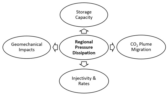
Figure 3.
Effects of regional pressure dissipation on future CCS projects.
3.1. Storage Capacity
One of the key factors that directly influence the success of CCS projects is the storage capacity of the chosen geological formation, typically an aquifer, where the CO2 is stored [24]. However, the effectiveness of CCS projects can be compromised by changes in regional pressure within the aquifer, as this directly impacts its storage capacity for CO2 [89].
The aquifer, which serves as the storage reservoir for CO2 in CCS projects, consists of porous and permeable rock formations that have the capacity to hold large volumes of CO2 [90]. The storage capacity is determined by various geological and physical characteristics, including the porosity of the rock, which is the measure of the void spaces within the formation, and the permeability, which refers to the ability of the formation to transmit fluids such as CO2 [91]. These formations are typically located deep underground and are often found in depleted oil and gas reservoirs or deep saline aquifers [92,93]. A crucial aspect of successful CO2 storage is the maintenance of sufficient pressure within the geological formation [54]. Pressure plays a pivotal role in keeping the CO2 in a dense and supercritical state, which is essential for it to remain in a liquid-like state and be effectively stored underground [94]. The pressure helps to counteract the temperature and keep the CO2 dense, preventing it from reverting to a gaseous state and leaking back to the surface [95]. This is why understanding and managing regional pressure changes within the aquifer is of utmost importance.
Over time, however, the regional pressure within the aquifer can change naturally due to a variety of factors, including the extraction of oil, gas, or other fluids from nearby reservoirs [96,97]. If the pressure in the aquifer significantly dissipates, it can lead to a reduction in the available pore space within the rock formation [98]. Pore space refers to the voids between rock particles where fluids like CO2 are stored. When this pore space diminishes due to pressure changes, the storage capacity of the aquifer for CO2 is reduced. In essence, the formation becomes less capable of accommodating the same volume of CO2 as it could when the pressure is higher. This reduction in storage capacity has direct implications for the CCS project’s overall effectiveness and duration [99].
CCS projects are designed to sequester large quantities of CO2 underground for extended periods, often decades to centuries. They play a vital role in achieving emissions reduction targets and mitigating the impacts of climate change [100]. However, if the storage capacity of the chosen aquifer decreases, the amount of CO2 that can be effectively stored within it also diminishes [24]. This can lead to several significant challenges: Firstly, the decrease in storage capacity restricts the amount of CO2 that can be injected and stored in the aquifer. This limitation can curtail the potential emissions reductions that the CCS project aims to achieve [101]. Then, the economic viability of the CCS project can be affected. A significant decrease in storage capacity might necessitate additional injections into multiple aquifers or the exploration of alternative storage sites. This can escalate costs and logistical complexities [102]. Another challenge is the duration over which the CCS project can effectively store CO2 is compromised. With limited storage space, the project’s operational life may be shortened, requiring more frequent interventions to manage and relocate the stored CO2 [8,103]. Finally, CCS projects often require substantial upfront investments. A decrease in storage capacity can introduce uncertainty and risk for investors, as the project’s long-term feasibility and potential returns are compromised [104,105].
To address these challenges, it becomes imperative to monitor and manage the regional pressure within the aquifer throughout the lifecycle of the CCS project. This involves ongoing geological monitoring, data analysis, and predictive modelling to anticipate pressure changes and adapt injection strategies accordingly. Additionally, it underscores the importance of thorough site characterization and selection, considering not only the initial storage capacity but also the potential for pressure changes over time.
3.2. CO2 Plume Migration
Understanding CO2 plume migration within aquifers is essential for ensuring the long-term integrity of CCS projects. When CO2 is injected into an aquifer, it ours differently from the liquid phase of water [106]. CO2 is less dense than brine, which is the predominant fluid in saline aquifers, and therefore tends to rise within the formation. This upward migration of CO2 is referred to as plume migration as shown in Figure 4 [107]. The plume migration process involves various complex physical and chemical interactions, including buoyancy, capillary forces, and mineral reactions [108,109]. Over time, the injected CO2 can migrate both vertically and laterally within the aquifer [110]. While some vertical migration is expected due to buoyancy, lateral migration can be influenced by the geologic properties of the formation, such as permeability and porosity [111].
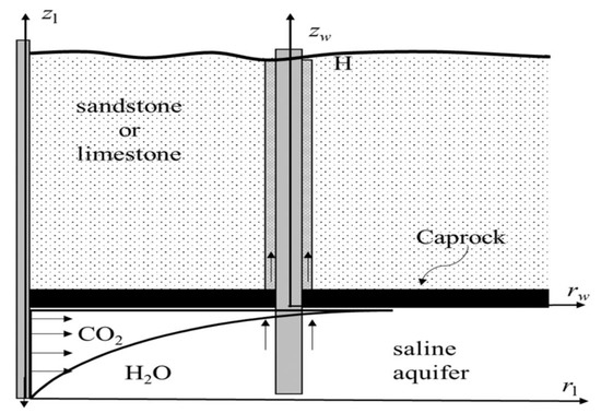
Figure 4.
The configuration of CO2 seepage within an abandoned well [106].
One of the critical factors that can significantly influence the behaviour of the CO2 plume within the aquifer is regional pressure changes [86]. Aquifers are not static environments; they are subject to various external factors that can lead to changes in subsurface pressure. These changes in pressure can have profound effects on the migration of the CO2 plume [112]. When the pressure decreases significantly in certain areas of the aquifer, it can create preferential pathways for CO2 migration. This occurs because areas with lower pressure provide less resistance to the upward movement of CO2 [113]. As a result, the CO2 plume may preferentially migrate towards these regions, bypassing other parts of the aquifer. This phenomenon is a cause for concern, as it can reduce the effectiveness of containment and increase the risk of leakage [114]. Then, the migration of the CO2 plume towards areas of reduced pressure increases the risk of leakage. If the plume reaches the aquifer’s boundaries or breaches caprock seals, it can escape into shallower geological formations or potentially reach the surface. Leakage of CO2 is a significant environmental concern, as it can compromise the effectiveness of CCS and pose risks to human health and the environment [115].
To mitigate the impact of pressure changes on CO2 plume behaviour, monitoring systems are essential. Continuous monitoring of pressure within the aquifer can provide early warning of pressure decreases and potential preferential migration pathways [116]. In response to such monitoring, injection rates can be adjusted, or additional measures, such as pressure maintenance, can be implemented to maintain containment [14]. Some regions of the aquifer may have higher permeability and porosity, making them more susceptible to pressure changes and CO2 migration. Understanding the geology of the aquifer is essential for predicting and managing pressure-related impacts [117].
Researchers and industry stakeholders have been conducting extensive studies and research efforts to better understand the interaction between regional pressure changes and CO2 plume migration [8,118]. Several case studies have provided valuable insights into the real-world challenges and solutions related to this issue. The Sleipner Project in the North Sea is one of the pioneering CCS projects that have been operating successfully for years. It involves the injection of CO2 into a saline aquifer beneath the seabed. The project has demonstrated the feasibility of geological storage and highlighted the importance of pressure monitoring and control in ensuring safe containment [119].
3.3. Injectivity and Rates
Injectivity, in the context of CCS, refers to the rate at which CO2 can be injected into an underground geological formation, typically an aquifer, and is measured in metric tons per year (MT/yr) [120]. It is a critical parameter as it directly influences the feasibility, efficiency, and economics of CCS projects. A high injectivity rate allows for the rapid and efficient injection of large volumes of CO2, facilitating the achievement of emission reduction targets [121]. Conversely, a low injectivity rate can significantly slow down the injection process, making CCS projects less efficient and potentially less cost-effective [122].
Several factors influence the injectivity rate in CCS projects. Understanding these factors is crucial for designing and operating successful CCS initiatives [123,124]. The geological properties of the selected storage site play a fundamental role in determining injectivity. The porosity and permeability of the rock formation are critical factors [125]. High porosity allows for greater CO2 storage capacity, while high permeability facilitates the movement of CO2 within the rock. Sites with low porosity and permeability may have reduced injectivity rates, making them less suitable for CCS [126]. In addition, pressure and temperature conditions at the storage site are vital for maintaining CO2 in a supercritical state, which is essential for efficient injection [86]. High pressure and appropriate temperature conditions increase the density of CO2, enabling more of it to be injected into the formation [127]. Moreover, the caprock, an impermeable layer of rock that overlays the storage formation, prevents the upward migration of injected CO2. The integrity of the caprock is crucial in ensuring the safety and long-term storage of CO2. Any breaches or fractures in the caprock can reduce injectivity and pose a risk of CO2 leakage [21]. The depth of the reservoir also influences the injectivity rate. Deeper reservoirs often have higher pressures, which can enhance injectivity [128]. However, drilling and operation costs also increase with greater depth, impacting the overall economics of CCS projects [129,130]. Furthermore, in-situ stress conditions within the geological formation can affect injectivity. High-stress conditions may lead to the formation of fractures, which can either enhance or reduce injectivity, depending on their orientation and connectivity [131,132]. The properties of the injected CO2, including its density, viscosity, and impurities, can influence injectivity. Impurities in the CO2 stream can lead to clogging or fouling of injection wells, reducing injectivity over time [133,134].
3.4. Geomechanical Impacts
As pressure dissipates within the storage reservoir, it can induce geomechanical changes, primarily compaction and subsidence. These phenomena have the potential to impact the stability of the storage reservoir and surrounding formations [135]. Pressure reduction within the reservoir can lead to the compaction of sedimentary rocks. As the pore spaces between grains shrink due to increased stress, the rock volume decreases. Compaction can result in reduced porosity and permeability, potentially affecting the injectivity and storage capacity of the reservoir [136]. Subsidence refers to the sinking or settling of the ground surface above the storage reservoir due to geomechanical changes. This can occur as a result of compaction or the redistribution of stress within the subsurface. Subsidence can have significant consequences for infrastructure, ecosystems, and surface water resources [35]. In 1948, there were vertical movements recorded in various areas of the Las Vegas Valley that exceeded 2 m when compared to the data from 1935. This resulted in substantial harm to roads, residences, and other structures, as illustrated in Figure 5 [137].
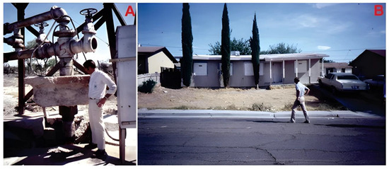
Figure 5.
(A) the elevation of drill pipes and (B) the destruction of a house in the Windsor Park District caused by land subsidence [137].
In CCS operations, the sealing formations, often comprised of impermeable cap rocks or layers, play a crucial role in preventing the upward migration of injected CO2 [138]. Pressure dissipation can affect the integrity of these sealing formations in several ways such as fault activation and cap rock failure. Pressure changes may activate pre-existing faults or induce the creation of new fractures in the sealing formations. This can compromise their sealing capacity, allowing CO2 to escape or migrate into overlying geological strata [54]. Excessive pressure dissipation can lead to cap rock failure, where the impermeable layer that should contain the CO2 ruptures or develops permeable pathways. This scenario poses a significant risk to the long-term security of the storage site [139]. Table 2 displays a set of distinct applied projects about the impact of regional pressure dissipation on storage capacity, CO2 plume migration, injectivity, and geomechanics.
Table 2.
Summary of the effect of the pressure dissipation on storage capacity, CO2 plume migration, injectivity, and geomechanics.
4. Investigation and Monitoring Strategies
A key aspect of managing pressure dissipation is the establishment of a robust pressure monitoring network. This network comprises a series of observation wells strategically placed within and around the storage reservoir. These wells provide real-time data on pressure changes, enabling project operators to detect any deviations from expected pressure behaviour promptly. Additionally, pressure monitoring can aid in understanding the movement and migration of CO2 within the reservoir. Modern technology, such as advanced downhole sensors and remote data transmission, has significantly improved the efficiency and accuracy of pressure monitoring [143].
In a case study from the Sleipner CCS project in the North Sea, a well-designed pressure monitoring network played a crucial role in preventing pressure build-up and induced seismicity [144]. By closely observing pressure changes, the operators were able to adjust injection rates and ensure that the reservoir’s pressure remained within safe limits. This proactive approach helped avoid potential caprock fractures and associated CO2 leakage [145].
Geomechanical modelling is another vital tool for assessing pressure dissipation and its potential impact [146]. It involves the construction of numerical models that simulate the behaviour of the storage reservoir and surrounding rock formations under varying pressure conditions. These models take into account factors such as rock porosity, permeability, and stress distribution [147]. By incorporating data from pressure monitoring networks and geological surveys, geomechanical models can predict how pressure changes may influence the stability of the storage reservoir and its containment structures.
The In Salah CCS project in Algeria offers an instructive example of effective geomechanical modelling. Here, simulations based on various pressure scenarios helped project planners determine optimal injection rates and pressure limits to prevent subsurface deformation and caprock failure [66,148]. These simulations also guided decisions on well placement and provided insights into potential pressure-related risks [43].
Pressure dissipation can trigger seismic events, commonly referred to as induced seismicity. These earthquakes, even if of low magnitude, can lead to public concern and impact project viability [149]. Advanced seismicity analysis involves closely monitoring and analysing seismic events associated with CCS operations. Seismic sensors deployed both near the injection well and in the vicinity of the storage reservoir can detect even minor tremors. By correlating seismic activity with pressure changes, operators can gain insights into the relationship between pressure dissipation and induced seismicity. In recent times, there has been a significant focus on the study of fault activation and induced seismic activity in connection with geological carbon sequestration (GCS) [150]. Most of the concerns revolve around the possibility of causing significant observable seismic events and how these events might affect both the long-term stability of a carbon dioxide (CO2) storage site and public perceptions of GCS (see Figure 6) [151].
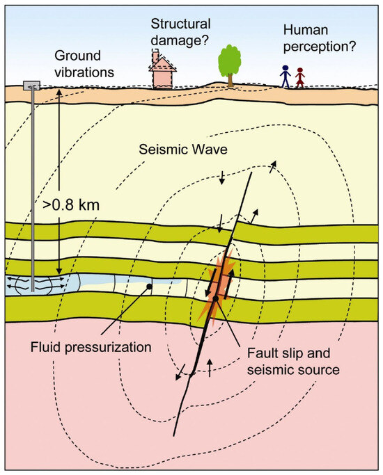
Figure 6.
A diagram of how fault reactivation induced by CO2 injection could potentially affect surface structures and how people perceive it [152].
The Hontomín CCS project in Spain exemplifies how advanced seismicity analysis can inform operational decisions [153]. By studying seismic events in conjunction with pressure data, project operators established thresholds beyond which injection rates were reduced or halted temporarily. This strategy allowed them to effectively manage induced seismicity while ensuring project continuity [154].
As CCS technology continues to evolve, ongoing research initiatives are exploring innovative ways to enhance pressure monitoring and mitigation strategies [14]. For instance, efforts are being made to incorporate machine learning algorithms to improve the accuracy of pressure forecasts based on historical data. Additionally, research is focused on developing real-time risk assessment frameworks that combine pressure, geomechanical, and seismic data to predict potential hazards [155].
In summary, pressure dissipation remains a central concern in CCS projects due to its potential to trigger adverse effects such as induced seismicity and caprock compromise. To tackle these challenges, comprehensive investigation and monitoring strategies are imperative. Pressure monitoring networks, geomechanical modelling, and advanced seismicity analysis collectively offer a robust approach to assessing and mitigating pressure-related risks. Through a combination of real-world case studies and ongoing research initiatives, the effectiveness of these strategies in predicting and managing pressure dissipation becomes evident. As the CCS field advances, the integration of these methodologies will be crucial for ensuring the safety and success of CCS projects worldwide. The pressure monitoring techniques and their impact on the Sleipner, In Salah, Quest, FutureGen 2.0, and Otway CCS projects are described in detail in Table 3. The efficacy, safety, and environmental sustainability of the Sleipner, In Salah, Quest, FutureGen 2.0, and Otway CCS projects are all enhanced by the different pressure monitoring techniques, as this extensive Table 3 demonstrates. To guarantee the successful execution of carbon capture and storage operations, each project makes use of a mix of these monitoring techniques.
Table 3.
Monitoring indicators and techniques for detecting CO2 leakage.
5. Case Studies
Carbon capture and storage (CCS) has emerged as a promising technology to mitigate greenhouse gas emissions and combat climate change. The success of CCS projects heavily depends on understanding and managing geological conditions, particularly pressure dissipation effects, in the target storage sites. This section presents a comprehensive analysis of notable case studies from various regions where CCS projects have been established or are under consideration. These case studies emphasize the local geological conditions, the observed or anticipated pressure dissipation effects, and the investigative approaches employed to assess and manage these effects.
Case Study 1: Sleipner Project—North Sea, Norway: The Sleipner CCS project, initiated in 1996, has been a pioneering example of effective pressure management in geological formations [145]. Located in the North Sea off the coast of Norway and is one of the world’s pioneering CCS initiatives, the project involves capturing CO2 from natural gas production and injecting it into the Utsira Formation, a deep saline aquifer, as shown in Figure 7 [119]. The geological structure of the formation includes layers of sandstone and shale, providing potential storage capacity for CO2. One of the key concerns in the Sleipner project was the potential for pressure build-up in the storage formation due to CO2 injection [163,164]. To address this issue, extensive modelling and monitoring activities were conducted to assess pressure dissipation effects. The approach involved seismic imaging, well pressure monitoring, and reservoir simulation to understand the behaviour of the injected CO2 and ensure safe storage. Researchers have observed minimal pressure perturbation in the reservoir due to the highly permeable cap rock and the presence of natural fractures, which allows for effective pressure dissipation. Monitoring techniques such as time-lapse seismic imaging and pressure gauges have been employed to assess pressure changes over time. The success of the Sleipner project in managing pressure dissipation has been attributed to the thorough geological characterization and the permeability of the cap rock [165].
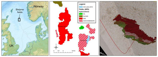
Figure 7.
On the left side, a map showing the location. In the middle, there is a depiction of the Sleipner fields with the outline of the CO2 plume from 2013. On the right, there is a seismic cross-section demonstrating the size of the CO2 plume in 2013 [119]. Reproduced with permission from [119], Elsevier, 2012.
Geological Conditions: The storage site features a layered geological structure with a thick shale caprock overlaying a sandstone reservoir. The sandstone provides porosity and permeability for CO2 storage [69].
Pressure Dissipation Effects: The injected CO2 at Sleipner was found to cause pressure build-up within the reservoir over time. This raised concerns about potential caprock fracturing or CO2 leakage [166]. However, extensive monitoring and pressure modelling revealed that the caprock integrity remained intact, and the pressure increase was well within the geological formation’s capacity to withstand. The injected CO2 was gradually dissipated and mineralized within the formation [167]. The injection of CO2 into the saline aquifer has led to an increase in pore pressure within the formation. However, due to the relatively high permeability of the caprock, pressure build-up was observed to dissipate relatively quickly through vertical migration. Monitoring data indicated that the pressure changes did not significantly affect the integrity of the caprock [163]. Moreover, Injection-induced pressure changes were observed within the reservoir. The relatively low-permeability overburden slowed pressure dissipation, emphasizing the importance of understanding the local geological characteristics [113].
Investigative Approaches: To assess pressure dissipation effects, the project utilized a combination of seismic monitoring, pressure measurements, water chemistry alterations, and computer simulations [168]. Regular seismic surveys allowed researchers to visualize subsurface changes and identify potential fractures or deformation. Pressure measurements helped validate the model predictions and adjust injection rates if necessary. These approaches collectively provided insights into the reservoir’s response to CO2 injection and its capacity to manage pressure. These observations confirmed pressure dissipation and informed the long-term safety of the storage site [163].
Case Study 2: In Salah CCS Project, Algeria: The In Salah CCS project, situated in the Sahara Desert of Algeria, commenced injection operations in 2004 [112]. It involves capturing CO2 from natural gas production and injecting it into the Krechba Formation, a deep saline aquifer beneath the Sahara Desert as shown in Figure 8 [169]. The project aims to mitigate CO2 emissions from natural gas production operations. The Krechba Formation is characterized by a complex geological structure with varying permeability and porosity levels [170]. The project provides insights into pressure dissipation effects in a hydrocarbon reservoir, which differ from those in a saline aquifer. The geological conditions include a layered sequence of sandstone and shale formations [156]. Researchers encountered pressure build-up challenges due to the low permeability of the shale layers, causing limited pressure dissipation. To manage this, the project implemented a pressure management strategy that involved adjusting injection rates and pressures based on real-time monitoring data. This adaptive approach allowed the project to prevent excessive pressure build-up and mitigate potential leakage risks [171]. The geology of the site comprises sandstone formations that hold the CO2 within porous rock layers [172]. Managing pressure build-up and preventing CO2 migration were key challenges. An innovative aspect of this project was the use of a monitoring well that allowed for direct measurement of pressure and composition changes in the reservoir. This approach facilitated an accurate assessment of pressure dissipation effects and the behaviour of the stored CO2 [150]. The findings from the In Salah project informed future CCS projects about the importance of direct measurements and the interaction between the injected CO2 and the host formation.
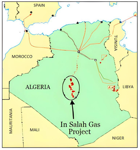
Figure 8.
The In Salah Gas Field [164]. Reproduced with permission from [170], Elsevier, 2009.
Geological Conditions: The storage reservoir is a natural gas field with sandstone formations containing hydrocarbons. CO2 was co-injected with produced gas to maintain reservoir pressure and enhance hydrocarbon recovery [14].
Pressure Dissipation Effects: Similar to other projects, pressure build-up was a concern in the In Salah project. The presence of hydrocarbons affects pressure dissipation. CO2 dissolution and hydrocarbon expansion counteract each other, resulting in slower pressure decline compared to saline aquifers [156]. However, the operators observed that the injected CO2 was dissolving into the formation water and mineralizing, leading to a decrease in pressure over time. The project also faced challenges due to the possibility of CO2-induced brine migration, leading to changes in porosity and permeability [170]. This natural pressure dissipation mechanism contributed to the overall security of the storage.
Investigative Approaches: Geological studies, including core samples and well logging, were performed to understand the reservoir’s characteristics. Detailed reservoir simulations incorporated compositional modelling of CO2-hydrocarbon interactions [173]. Seismic monitoring and well data analysis were conducted to understand reservoir behaviour. The project demonstrated that CO2 storage can be effectively managed in hydrocarbon reservoirs, but specific considerations are needed due to the coexistence of CO2 and hydrocarbons [174].
Case Study 3: Quest Project—Alberta, Canada: The Quest CCS project, located in Alberta, Canada, has been operational since 2015, as shown in Figure 9 [158]. It focuses on capturing CO2 emissions from a bitumen-upgrading facility and injecting them into a deep saline aquifer within the Basal Cambrian Sands in Alberta. The local geological conditions comprise several permeable sandstone layers separated by impermeable shale formations. Researchers anticipated pressure build-up due to the limited lateral migration of CO2 within the reservoir [16]. To address this, the project incorporated a comprehensive pressure management strategy that involved continuous monitoring, regular assessment of pressure data, and adjustment of injection parameters. This strategy enabled the project to maintain safe pressure levels and prevent any adverse effects on the geological formations. This case study highlights the importance of regional geological variations on pressure dissipation.
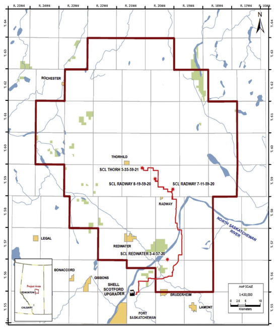
Figure 9.
The Quest CCS project’s location, with a dark red boundary outlining the Quest sequestration lease area, while the light red represents the underground pipeline [158]. Reproduced with permission from [158], Elsevier, 2019.
Geological Conditions: The geology of the region includes a combination of sedimentary rock formations with varying permeabilities and porosities. The geological setting is characterized by thick sequences of sandstone and limestone. The storage site is characterized by thick layers of sandstone and shale. The injection site is beneath multiple geological layers, including a confining shale caprock [175].
Pressure Dissipation Effects: The injection of CO2 led to an initial pressure increase, followed by pressure stabilization due to caprock integrity and mineral trapping. However, regional geological variations led to uneven pressure distribution [176]. The geological conditions in Alberta presented a unique challenge due to the presence of multiple formations with varying permeabilities. This demanded an intricate understanding of pressure migration [158].
Investigative Approaches: A combination of geophysical surveys, reservoir modelling, and subsurface monitoring helped assess pressure distribution and caprock integrity. Comprehensive seismic surveys were conducted to map the subsurface geological structures and identify suitable storage sites [157]. A multi-phase pressure management strategy was implemented, including initial pressure build-up followed by controlled dissipation. Geomechanical modelling helped assess potential pressure-induced stress changes in the surrounding rock layers. Researchers emphasized the significance of understanding regional geological heterogeneity to ensure safe long-term storage [37,157,176].
Case Study 4: FutureGen 2.0 Project—Illinois, USA: The FutureGen 2.0 CCS project, under consideration, aims to retrofit an existing coal-fired power plant with CCS technology and store the captured CO2 in the Mount Simon Sandstone formation as shown in Figure 10. The geology of the region consists of multiple layered formations, including sandstone and shale layers. The geological formation of interest is a deep saline reservoir with layered sandstone and shale [159].
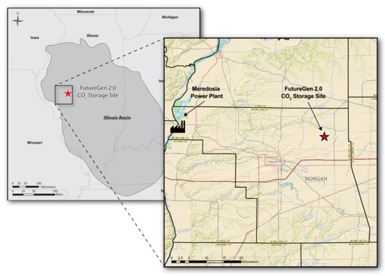
Figure 10.
The CO2 storage site’s positions in the Illinois Basin (on the left) and within Morgan County (on the right) [159].
Geological Conditions: The geological conditions comprise layered sedimentary rocks with a thick caprock above the storage formation. Also, it consists of coal beds surrounded by various rock layers. Managing pressure build-up and ensuring the integrity of seals are critical aspects [154].
Pressure Dissipation Effects: Given the complex geological setting, predicting pressure dissipation effects is challenging. The project has focused on conducting thorough reservoir simulations and utilizing advanced geophysical techniques to understand subsurface behaviour [177]. While pressure build-up is expected, the project aims to ensure that caprock integrity remains intact [178]. Furthermore, numerical modelling assessed pressure propagation and migration pathways, guiding injection strategies [161].
Investigative Approaches: The FutureGen 2.0 project emphasizes a multidisciplinary approach to investigate pressure dissipation effects [179]. Advanced seismic imaging techniques, coupled with petrophysical analysis and laboratory experiments, are used to characterize the storage formation and assess its response to CO2 injection. Real-time pressure monitoring and continuous model refinement play a crucial role in ensuring the project’s success [180].
Case Study 5: Otway CCS Project, Victoria, Australia: The Otway CCS project, located in Victoria, Australia, involves injecting CO2 into a depleted gas reservoir within a sandstone formation for research purposes as shown in Figure 11 [181].
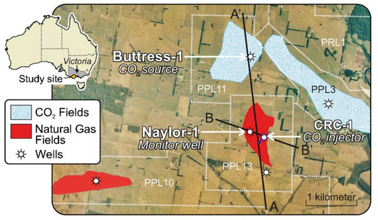
Figure 11.
The map indicates the location of the CO2 CRC Otway Project [181]. Reproduced with permission from [181], Elsevier, 2011.
Geological Conditions: The geological conditions in this region involve a layered sedimentary sequence, with potential sealing mechanisms provided by shale layers [182].
Pressure Dissipation Effects: The Otway project emphasized studying the interactions between CO2 and rock formation to ensure pressure dissipation [162]. Monitoring indicated that CO2 was effectively adsorbed onto the rock surfaces, reducing the potential for excessive pressure build-up [183].
Investigative Approaches: Comprehensive laboratory experiments and field studies were conducted to understand CO2-rock interactions. This included analysing rock samples and measuring adsorption capacities to quantify the extent of CO2 immobilization and pressure reduction [183].
The perspective offered in the detailed study of carbon capture and storage (CCS) projects emphasizes the importance of knowing and regulating geological conditions, notably pressure dissipation effects, at the target storage sites. A comprehensive review of prominent case studies from diverse places reveals that successful CCS deployment is dependent on a thorough understanding of local geological characteristics and the use of appropriate investigative methodologies.
The case studies discussed, which include the Sleipner Project in the North Sea, the In Salah CCS Project in Algeria, the Quest Project in Alberta, Canada, the FutureGen 2.0 Project in Illinois, USA, and the Otway CCS Project in Victoria, Australia, each offer unique perspectives on the challenges and strategies associated with pressure management in CCS initiatives. Table 4 presents a more extensive assessment of each CCS project’s important outcomes and successes, focusing on CO2 storage capacity, operational duration, and key milestones.
Table 4.
Summary of the quantitated outcomes of the case studies [144,145,156,157,158,161,162,171,182].
One of the key takeaways from these case studies is the critical role of geological conditions in determining the efficacy of pressure dissipation mechanisms. For example, the Sleipner Project emphasizes the significance of highly permeable cap rock and natural fissures for effective pressure dissipation. In contrast, initiatives like the In Salah CCS Project faced difficulty due to limited permeability shale strata, necessitating adaptive pressure control systems.
Furthermore, the investigative tactics used in these projects demonstrate the interdisciplinary nature of CCS research, which includes techniques like seismic monitoring, reservoir simulation, geophysical surveys, and laboratory experimentation. These methods not only allow researchers to evaluate pressure dissipation effects, but they also provide useful information about CO2-rock interactions and possible storage capacity.
Furthermore, the case studies underscore the importance of ongoing monitoring and adjustment of injection settings to ensure the long-term safety and efficacy of CCS projects. The dynamic nature of pressure dissipation necessitates a proactive strategy to reduce possible dangers and increase storage efficiency.
Overall, the analysis highlights the intricate interplay of geological factors, pressure dissipation effects, and investigation methodologies in CCS projects. Researchers and policymakers can use the insights acquired from these case studies to establish solid strategies for reducing greenhouse gas emissions and combatting climate change using CCS technology. Consequently, localized injection strategies, zoning reservoirs for pressure management to enable focused monitoring and adjustment, improved reservoir characterization to comprehend geological features, pressure-dependent injection rates, horizontal wellbore utilization for accurate injection, geochemical tracer deployment to track CO2 movement, and integrated monitoring and control systems for proactive management are additional controls for regional pressure dissipation in CCS. By taking these steps, CCS operations can minimize pressure-related risks, optimize CO2 storage capacity, and assure effective pressure management.
6. Future Directions and Challenges
The future directions and challenges related to the impact of regional pressure dissipation on CCS projects, with a focus on its effects and investigations, are explored below.
6.1. Future Directions for Regional Pressure Dissipation in CCS
6.1.1. Advanced Monitoring Technologies
Future CCS projects will benefit from the development and integration of advanced monitoring technologies. These include real-time pressure sensors, satellite-based monitoring, and geophysical methods, allowing for continuous assessment of pressure changes and ensuring the early detection of anomalies [184].
6.1.2. Predictive Modelling
The use of predictive modelling and simulation tools will become increasingly crucial for estimating the regional pressure dissipation long-term effects. These models can help optimize injection rates and schedules to minimize pressure build-up and potential risks [185,186].
6.1.3. Risk Mitigation Strategies
Future CCS projects should incorporate robust risk mitigation strategies related to pressure dissipation. These may include the implementation of pressure relief systems, emergency response plans, and the use of natural barriers to contain CO2 [36].
6.1.4. International Collaboration
Collaboration at the international level will be necessary to address global challenges associated with CCS and regional pressure dissipation. Sharing best practices, data, and experiences can help enhance the safety and efficiency of CCS projects worldwide [121].
6.2. Challenges in Investigating Regional Pressure Dissipation in CCS
6.2.1. Lack of Long-Term Data
Long-term data on pressure dissipation effects in CCS projects are limited. Gathering extensive data over several decades is essential to understand how regional pressures evolve and the potential long-term consequences [36].
6.2.2. Environmental and Ecological Impacts
Investigating the environmental and ecological impacts of regional pressure dissipation is challenging. Researchers must assess how changes in pressure affect groundwater, local ecosystems, and human populations living near storage sites [187].
6.2.3. Regulatory and Policy Frameworks
The absence of comprehensive regulatory and policy frameworks for regional pressure dissipation in CCS is a significant challenge. Governments and international organizations need to establish clear guidelines to ensure the safe and responsible operation of CCS projects [188].
6.2.4. Public Perception and Engagement
Public perception and engagement are crucial for the success of CCS projects. Effective communication and transparency about the investigation and management of regional pressure dissipation can address concerns and build trust [189]. For example, surface uplift measurements at Salah yielded the initial evidence of geomechanical deformation, indicating displacements of approximately 1 cm per year cantered on each of the three injection wells, thereby constraining the magnitude and extent of this uplift, with studies revealing a surface rise of approximately 2 cm over a 5-year injection period [134].
The future of CCS projects relies on addressing the challenges and opportunities related to regional pressure dissipation. There are a number of obstacles facing future research on how regional pressure dissipation affects CCS projects. First, to accurately forecast pressure dissipation behaviour over extended periods of time, a better knowledge of the intricate interactions between injected CO2, adjacent aquifers, and geological formations is required. Furthermore, it is still difficult to create accurate predictive models that take subsurface conditions, fluid flow dynamics, and reservoir characteristics into account. In addition, a large investment and advancement in technology are needed to integrate cutting-edge monitoring technologies and data analytics tools into the current CCS infrastructure to enable real-time monitoring and control of pressure dynamics. Moreover, obstacles to the broad implementation of CCS projects include resolving policy and regulatory ambiguities about long-term liability, monitoring requirements, and stakeholder engagement. To enable the safe and successful adoption of CCS as a climate mitigation approach, overcoming these obstacles will ultimately need multidisciplinary collaboration, creative research, and coordinated efforts from business, academia, and regulatory organizations. Therefore, the development of advanced monitoring technologies, predictive modelling, and international collaboration will be critical for safe and effective CO2 sequestration. Investigating the effects of pressure dissipation and implementing risk mitigation strategies are essential steps in ensuring the success of CCS projects and their contribution to global climate change mitigation efforts. As the field of CCS continues to evolve, ongoing research and investigation into regional pressure dissipation will be crucial for its sustainability and effectiveness.
7. Conclusions
The impact of regional pressure dissipation on CCS projects is a critical consideration that affects the safety, efficiency, and overall feasibility of these endeavours. The variability in regional pressure dissipation must be addressed through careful site selection, comprehensive investigations, robust monitoring, and effective risk mitigation strategies.
Understanding and managing geomechanical effects, such as subsidence, fault activation, and induced seismicity, are essential to ensure the safety and sustainability of CCS projects. At Sleipner, 4D seismic datasets are utilized to monitor pressure variations, revealing negligible time-lapse travel-time variations outside the CO2 injection plume footprint, consistent with pressure increases up to 2006 of less than 0.1 MPa within distances of 500 m to 4000 m from the injection location. Moreover, surface uplift measurements at Salah project yielded the initial evidence of geomechanical deformation, indicating displacements of approximately 1 cm per year centred on each of the three injection wells, thereby constraining the magnitude and extent of this uplift, with studies revealing a surface rise of approximately 2 cm over a 5-year injection period. Furthermore, The Jurong depleted oil reserve, with its geological conditions, is subjected to artificial CO2 injection and storage through the use of numerical models. With a maximum volume of 5.43 × 10⁶ metric tons, the injection is carried out over a 30-year period, resulting in a significant increase in formation pressure of up to 9.5 MPa. Over the 300 years that followed injection, CO2 moved and spread throughout the reservoir, with gas-phase CO2 saturation preserving stability and security.
Regulatory frameworks and public engagement are crucial components in addressing the potential effects of regional pressure dissipation and building trust within communities, as over 20 million tons of CO2 is stored in Sleipner and In Salah projects, and over 5 million tons of CO2 is injected in Quest project. However, precisely forecasting and controlling pressure dynamics throughout time is a major difficulty for all of these initiatives. Optimization of injection techniques and containment integrity is severely hampered by the complexity of subsurface interactions and uncertainty in reservoir behaviour and fluid flow. Addressing this challenge will necessitate further advances in predictive modelling, improved monitoring technology, and strong risk management techniques. Furthermore, establishing clear legal frameworks and addressing public perception concerns are critical for overcoming barriers and promoting wider acceptance of CCS as a viable climate mitigation approach.
Through international collaboration and knowledge-sharing, the global community can work together to advance CCS technology and accelerate its adoption as a critical tool in the fight against climate change. It is through these collective efforts that CCS can contribute significantly to reducing carbon emissions and mitigating the impact of global warming.
Author Contributions
H.K.H. contributed to conceptualization, data preparation, technical writing, and interpretation. T.A. identified as the corresponding author, played a key role in the conceptualization, review, editing, feedback, and writing. All authors have read and agreed to the published version of the manuscript.
Funding
This research received no external funding.
Conflicts of Interest
The authors declare no conflicts of interest.
References
- Gielen, D.; Boshell, F.; Saygin, D.; Bazilian, M.D.; Wagner, N.; Gorini, R. The role of renewable energy in the global energy transformation. Energy Strategy Rev. 2019, 24, 38–50. [Google Scholar] [CrossRef]
- Farghali, M.; Osman, A.I.; Chen, Z.; Abdelhaleem, A.; Ihara, I.; Mohamed, I.M.A.; Yap, P.-S.; Rooney, D.W. Social, environmental, and economic consequences of integrating renewable energies in the electricity sector: A review. Environ. Chem. Lett. 2023, 21, 1381–1418. [Google Scholar] [CrossRef]
- Shu, D.Y.; Deutz, S.; Winter, B.A.; Baumgärtner, N.; Leenders, L.; Bardow, A. The role of carbon capture and storage to achieve net-zero energy systems: Trade-offs between economics and the environment. Renew. Sustain. Energy Rev. 2023, 178, 113246. [Google Scholar] [CrossRef]
- Ratanpara, A.; Ricca, J.G.; Gowda, A.; Abraham, A.; Wiskoff, S.; Zauder, V.; Sharma, R.; Hafez, M.; Kim, M. Towards green carbon capture and storage using waste concrete based seawater: A microfluidic analysis. J. Environ. Manag. 2023, 345, 118760. [Google Scholar] [CrossRef] [PubMed]
- McLaughlin, H.; Littlefield, A.A.; Menefee, M.; Kinzer, A.; Hull, T.; Sovacool, B.K.; Bazilian, M.D.; Kim, J.; Griffiths, S. Carbon capture utilization and storage in review: Sociotechnical implications for a carbon reliant world. Renew. Sustain. Energy Rev. 2023, 177, 113215. [Google Scholar] [CrossRef]
- Davoodi, S.; Al-Shargabi, M.; Wood, D.A.; Rukavishnikov, V.S.; Minaev, K.M. Review of technological progress in carbon dioxide capture, storage, and utilization. Gas Sci. Eng. 2023, 117, 205070. [Google Scholar] [CrossRef]
- Eldardiry, H.; Habib, E. Carbon capture and sequestration in power generation: Review of impacts and opportunities for water sustainability. Energy Sustain. Soc. 2018, 8. [Google Scholar] [CrossRef]
- Ketzer, J.M.; Iglesias, R.S.; Einloft, S. Reducing Greenhouse Gas Emissions with CO2 Capture and Geological Storage. In Handbook of Climate Change Mitigation and Adaptation; Chen, W.-Y., Seiner, J., Suzuki, T., Lackner, M., Eds.; Springer: New York, NY, USA, 2012; Volume 3, pp. 1405–1440. [Google Scholar]
- Liu, X.; Asim, A.; Zhu, G.; Mishra, R. Theoretical and experimental investigations on the combustion characteristics of three components mixed municipal solid waste. Fuel 2020, 267, 117183. [Google Scholar] [CrossRef]
- Becattini, V.; Gabrielli, P.; Antonini, C.; Campos, J.; Acquilino, A.; Sansavini, G.; Mazzotti, M. Carbon dioxide capture, transport and storage supply chains: Optimal economic and environmental performance of infrastructure rollout. Int. J. Greenh. Gas Control 2022, 117, 103635. [Google Scholar] [CrossRef]
- Chen, X.; Zhang, Q.; Trivedi, J.; Li, Y.; Liu, J.; Liu, Z.; Liu, S. Investigation on enhanced oil recovery and CO2 storage efficiency of temperature-resistant CO2 foam flooding. Fuel 2024, 364, 130870. [Google Scholar] [CrossRef]
- Tan, Z.; Zeng, X.; Lin, B. How do multiple policy incentives influence investors’ decisions on biomass co-firing combined with carbon capture and storage retrofit projects for coal-fired power plants? Energy 2023, 278, 127822. [Google Scholar] [CrossRef]
- Zhang, L.; Wang, Y.; Miao, X.; Gan, M.; Li, X. Geochemistry in geologic CO2 utilization and storage: A brief review. Adv. Geo-Energy Res. 2019, 3, 304–313. [Google Scholar] [CrossRef]
- Ajayi, T.; Gomes, J.S.; Bera, A. A review of CO2 storage in geological formations emphasizing modeling, monitoring and capacity estimation approaches. Pet. Sci. 2019, 16, 1028–1063. [Google Scholar] [CrossRef]
- Proelss, A.; Steenkamp, R.C. Geoengineering: Methods, Associated Risks and International Liability. In Corporate Liability for Transboundary Environmental Harm: An International and Transnational Perspective; Gailhofer, P., Krebs, D., Proelss, A., Schmalenbach, K., Eds.; Springer: Cham, Switzerland, 2023. [Google Scholar]
- Qiao, X.; Li, G.; Li, M.; Wang, Z. CO2 storage capacity assessment of deep saline aquifers in the Subei Basin, East China. Int. J. Greenh. Gas Control 2012, 11, 52–63. [Google Scholar] [CrossRef]
- Yeo, I.W.; Brown, M.R.M.; Ge, S.; Lee, K.K. Causal mechanism of injection-induced earthquakes through the Mw 5.5 Pohang earthquake case study. Nat. Commun. 2020, 11, 2614. [Google Scholar] [CrossRef] [PubMed]
- Hamza, A.; Hussein, I.A.; Al-Marri, M.J.; Mahmoud, M.; Shawabkeh, R.; Aparicio, S. CO2 enhanced gas recovery and sequestration in depleted gas reservoirs: A review. J. Pet. Sci. Eng. 2021, 196, 107685. [Google Scholar] [CrossRef]
- Vafaie, A.; Cama, J.; Soler, J.M.; Kivi, I.R.; Vilarrasa, V. Chemo-hydro-mechanical effects of CO2 injection on reservoir and seal rocks: A review on laboratory experiments. Renew. Sustain. Energy Rev. 2023, 178, 113270. [Google Scholar] [CrossRef]
- Song, Y.; Jun, S.; Na, Y.; Kim, K.; Jang, Y.; Wang, J. Geomechanical challenges during geological CO2 storage: A review. Chem. Eng. J. 2023, 456, 140968. [Google Scholar] [CrossRef]
- Jacobs, H.; Gupta, A.; Möller, I. Governing-by-aspiration? Assessing the nature and implications of including negative emission technologies (NETs) in country long-term climate strategies. Glob. Environ. Chang. 2023, 81, 102691. [Google Scholar] [CrossRef]
- Almena, A.; Thornley, P.; Chong, K.; Röder, M. Carbon dioxide removal potential from decentralised bioenergy with carbon capture and storage (BECCS) and the relevance of operational choices. Biomass Bioenergy 2022, 159, 106406. [Google Scholar] [CrossRef]
- Ali, M.; Jha, N.K.; Pal, N.; Keshavarz, A.; Hoteit, H.; Sarmadivaleh, M. Recent advances in carbon dioxide geological storage, experimental procedures, influencing parameters, and future outlook. Earth-Sci. Rev. 2022, 225, 103895. [Google Scholar] [CrossRef]
- Ismail, I.; Gaganis, V. Carbon Capture, Utilization, and Storage in Saline Aquifers: Subsurface Policies, Development Plans, Well Control Strategies and Optimization Approaches—A Review. Clean Technol. 2023, 5, 609–637. [Google Scholar] [CrossRef]
- Marbun, B.T.H.; Sinaga, S.Z.; Purbantanu, B.; Santoso, D.; Kadir, W.G.A.; Sule, R.; Prasetyo, D.; Prabowo, H.; Susilo, D.; Firmansyah, F.; et al. Lesson learned from the assessment of planned converted CO2 injection well integrity in Indonesia—CCUS project. Heliyon 2023, 9, e18505. [Google Scholar] [CrossRef] [PubMed]
- Stokes, S.M.; Ge, S.; Brown, M.R.M.; Menezes, E.A.; Sheehan, A.F.; Tiampo, K.F. Pore Pressure Diffusion and Onset of Induced Seismicity. J. Geophys. Res. Solid Earth 2023, 128. [Google Scholar] [CrossRef]
- White, J.A.; Foxall, W. Assessing induced seismicity risk at CO2 storage projects: Recent progress and remaining challenges. Int. J. Greenh. Gas Control 2016, 49, 413–424. [Google Scholar] [CrossRef]
- Ge, S.; Saar, M.O. Review: Induced Seismicity During Geoenergy Development—A Hydromechanical Perspective. J. Geophys. Res. Solid Earth 2022, 127, e2021JB023141. [Google Scholar] [CrossRef]
- Rowan, L.R.; Jones, A.C. Earthquakes Induced by Underground Fluid Injection and the Federal Role in Mitigation Earth-quakes Induced by Underground Fluid Injection and the Federal Role in Mitigation. 2023. Available online: https://www.osti.gov/servlets/purl/4111086 (accessed on 1 April 2024).
- Kivi, I.R.; Boyet, A.; Wu, H.; Walter, L.; Hanson-hedgecock, S.; Parisio, F.; Vilarrasa, V. Global physics-based database of injection-induced seismicity. Earth Syst. Sci. Data 2023, 1–33. [Google Scholar] [CrossRef]
- Newell, P.; Martinez, M. Numerical assessment of fault impact on caprock seals during CO2 sequestration. Int. J. Greenh. Gas Control 2020, 94, 102890. [Google Scholar] [CrossRef]
- Tewari, R.D.; Phuat, T.C.; Sedaralit, M.F. A Toolkit Approach for Carbon Capture and Storage in Offshore Depleted Gas Field. Am. J. Environ. Sci. 2023, 19, 8–42. [Google Scholar] [CrossRef]
- Riel, B.; Simons, M.; Ponti, D.; Agram, P.; Jolivet, R. Quantifying Ground Deformation in the Los Angeles and Santa Ana Coastal Basins Due to Groundwater Withdrawal. Water Resour. Res. 2018, 54, 3557–3582. [Google Scholar] [CrossRef]
- Coda, S.; Confuorto, P.; De Vita, P.; Di Martire, D.; Allocca, V. Uplift Evidences related to the recession of groundwater abstraction in a pyroclastic-alluvial aquifer of southern Italy. Geosciences 2019, 9, 215. [Google Scholar] [CrossRef]
- Guzy, A.; Malinowska, A.A. State of the art and recent advancements in the modelling of land subsidence induced by groundwater withdrawal. Water 2020, 12, 2051. [Google Scholar] [CrossRef]
- Rasool, M.H.; Ahmad, M.; Ayoub, M. Selecting Geological Formations for CO2 Storage: A Comparative Rating System. Sustainability 2023, 15, 6599. [Google Scholar] [CrossRef]
- Liu, X.; Zhu, G.; Asim, T.; Mishra, R. Combustion characterization of hybrid methane-hydrogen gas in domestic swirl stoves. Fuel 2023, 333, 126413. [Google Scholar] [CrossRef]
- Zapata, Y.; Kristensen, M.R.; Huerta, N.; Brown, C.; Kabir, C.S.; Reza, Z. CO2 geological storage: Critical insights on plume dynamics and storage efficiency during long-term injection and post-injection periods. J. Nat. Gas Sci. Eng. 2020, 83, 103542. [Google Scholar] [CrossRef]
- Shad, S.; Razaghi, N.; Zivar, D.; Mellat, S. Mechanical behavior of salt rocks: A geomechanical model. Petroleum 2022, 9, 508–525. [Google Scholar] [CrossRef]
- Kim, K.; Vilarrasa, V.; Makhnenko, R.Y. CO2 injection effect on geomechanical and flow properties of calcite-rich reservoirs. Fluids 2018, 3, 66. [Google Scholar] [CrossRef]
- Cai, M.; Su, Y.; Li, L.; Hao, Y.; Gao, X. CO2-Fluid-Rock Interactions and the Coupled Geomechanical Response during CCUS Processes in Unconventional Reservoirs. Geofluids 2021, 2021. [Google Scholar] [CrossRef]
- Ebner, M.; Schirpke, U.; Tappeiner, U. How do anthropogenic pressures affect the provision of ecosystem services of small mountain lakes? Anthropocene 2022, 38, 100336. [Google Scholar] [CrossRef]
- Abbass, K.; Qasim, M.Z.; Song, H.; Murshed, M.; Mahmood, H.; Younis, I. A review of the global climate change impacts, adaptation, and sustainable mitigation measures. Environ. Sci. Pollut. Res. 2022, 29, 42539–42559. [Google Scholar] [CrossRef]
- Kalam, S.; Olayiwola, T.; Al-Rubaii, M.M.; Amaechi, B.I.; Jamal, M.S.; Awotunde, A.A. Carbon dioxide sequestration in underground formations: Review of experimental, modeling, and field studies. J. Pet. Explor. Prod. Technol. 2020, 11, 303–325. [Google Scholar] [CrossRef]
- Asim, T.; Mishra, R.; Ubbi, K.; Zala, K. Computational fluid dynamics based optimal design of vertical axis marine current turbines. Procedia CIRP 2013, 11, 323–327. [Google Scholar] [CrossRef]
- Hu, J.; Wang, Q.; Zhang, Y.; Meng, Z.; Zhang, J.; Fan, J. Numerical and Experimental Study on the Process of Filling Water in Pressurized Water Pipeline. Water 2023, 15, 2508. [Google Scholar] [CrossRef]
- Asim, T. Computational Fluid Dynamics Based Diagnostics and Optimal Design of Hydraulic Capsule Pipelines. Ph.D. Thesis, University of Huddersfield, Huddersfield, UK, 2013. [Google Scholar]
- Kim, M.C.; Yadav, D. Linear and Nonlinear Analyses of the Onset of Buoyancy-Induced Instability in an Unbounded Porous Medium Saturated by Miscible Fluids. Transp. Porous Media 2014, 104, 407–433. [Google Scholar] [CrossRef]
- Freegah, B.; Asim, T.; Mishra, R. Computational Fluid Dynamics based Analysis of a Closed Thermo-Siphon Hot Water Solar System. In Proceedings of the 26th International Congress on Condition Monitoring and Diagnostic Engineering Management, Helsinki, Finland, 26–28 May 2013. [Google Scholar]
- Kocharyan, G.G.; Ostapchuk, A.A.; Pavlov, D.V.; Gridin, G.A.; Morozova, K.G.; Hongwen, J.; Panteleev, I.A. Laboratory Study on Frictional Behavior of Rock Blocks of Meter Scale. Methods and Preliminary Results. Izv. Phys. Solid Earth 2022, 58, 929–940. [Google Scholar] [CrossRef]
- Singh, D.; Charlton, M.; Asim, T.; Mishra, R.; Townsend, A.; Blunt, L. Quantification of additive manufacturing induced variations in the global and local performance characteristics of a complex multi-stage control valve trim. J. Pet. Sci. Eng. 2020, 190, 107053. [Google Scholar] [CrossRef]
- Askarova, A.; Mukhametdinova, A.; Markovic, S.; Khayrullina, G.; Afanasev, P.; Popov, E.; Mukhina, E. An Overview of Geological CO2 Sequestration in Oil and Gas Reservoirs. Energies 2023, 16, 2821. [Google Scholar] [CrossRef]
- Arora, V.; Saran, R.K.; Kumar, R.; Yadav, S. Separation and sequestration of CO2 in geological formations. Mater. Sci. Energy Technol. 2019, 2, 647–656. [Google Scholar] [CrossRef]
- Zheng, H.; Shi, Z.; Kaitna, R.; Zhao, F.; de Haas, T.; Hanley, K.J. Control mechanisms of pore-pressure dissipation in debris flows. Eng. Geol. 2023, 317, 107076. [Google Scholar] [CrossRef]
- Al Hameli, F.; Belhaj, H.; Al Dhuhoori, M. CO2 Sequestration Overview in Geological Formations: Trapping Mechanisms Matrix Assessment. Energies 2022, 15, 7805. [Google Scholar] [CrossRef]
- Gheibi, S.; Holt, R.M.; Vilarrasa, V. Effect of faults on stress path evolution during reservoir pressurization. Int. J. Greenh. Gas Control 2017, 63, 412–430. [Google Scholar] [CrossRef]
- Kivi, I.R.; Pujades, E.; Rutqvist, J.; Vilarrasa, V. Cooling-induced reactivation of distant faults during long-term geothermal energy production in hot sedimentary aquifers. Sci. Rep. 2022, 12. [Google Scholar] [CrossRef] [PubMed]
- Kukha Hawez, H. Coupled Geomechanics and Transient Multiphase Flow at Fracture-Matrix Interface in Tight Reservoirs. Ph.D. Thesis, Robert Gordon University, Aberdeen, UK, 2023. [Google Scholar] [CrossRef]
- Kruszewski, M.; Montegrossi, G.; Saenger, E.H. The risk of fluid-injection-induced fault reactivation in carbonate reservoirs: An investigation of a geothermal system in the Ruhr region (Germany). Geomech. Geophys. Geo-Energy Geo-Resour. 2023, 9, 38. [Google Scholar] [CrossRef]
- Liu, Q.; Zhu, D.; Jin, Z.; Tian, H.; Zhou, B.; Jiang, P.; Meng, Q.; Wu, X.; Xu, H.; Hu, T.; et al. Carbon capture and storage for long-term and safe sealing with constrained natural CO2 analogs. Renew. Sustain. Energy Rev. 2023, 171, 113000. [Google Scholar] [CrossRef]
- Yadav, D.; Kim, M.C. The onset of transient soret-driven buoyancy convection in nanoparticle suspensions with particle-concentration-dependent viscosity in a porous medium. J. Porous Media 2015, 18, 369–378. [Google Scholar] [CrossRef]
- Wetenhall, B.; Race, J.M.; Downie, M.J. The Effect of CO2 Purity on the Development of Pipeline Networks for Carbon Capture and Storage Schemes. Int. J. Greenh. Gas Control 2014, 30, 197–211. [Google Scholar] [CrossRef]
- Szulczewski, M.L.; MacMinn, C.W.; Herzog, H.J.; Juanes, R. Lifetime of carbon capture and storage as a climate-change mitigation technology. Proc. Natl. Acad. Sci. USA 2012, 109, 5185–5189. [Google Scholar] [CrossRef]
- Zhai, X.; Atefi-Monfared, K. Production versus injection induced poroelasticity in porous media incorporating fines migration. J. Pet. Sci. Eng. 2021, 205, 108953. [Google Scholar] [CrossRef]
- Babasafari, A.A.; Ghosh, D.P.; Ratnam, T.; Rezaei, S.; Sambo, C. Geological reservoir modeling and seismic reservoir monitoring. In Seismic Imaging Methods and Applications for Oil and Gas Exploration; Elsevier: Amsterdam, The Netherlands, 2022; pp. 179–285. [Google Scholar] [CrossRef]
- Zheng, X.; Espinoza, D.N.; Vandamme, M.; Pereira, J.-M. CO2 plume and pressure monitoring through pressure sensors above the caprock. Int. J. Greenh. Gas Control 2022, 117, 103660. [Google Scholar] [CrossRef]
- Jun, S.; Song, Y.; Wang, J.; Weijermars, R. Formation uplift analysis during geological CO2-Storage using the Gaussian pressure transient method: Krechba (Algeria) validation and South Korean case studies. Geoenergy Sci. Eng. 2023, 221, 211404. [Google Scholar] [CrossRef]
- Putnis, A. Transient Porosity Resulting from Fluid—Mineral. Rev. Miner. Geochem. 2015, 80, 1–23. [Google Scholar] [CrossRef]
- Fawad, M.; Rahman, J.; Mondol, N.H. Seismic reservoir characterization of potential CO2 storage reservoir sandstones in Smeaheia area, Northern North Sea. J. Pet. Sci. Eng. 2021, 205, 108812. [Google Scholar] [CrossRef]
- Cappa, F.; Guglielmi, Y.; Nussbaum, C.; De Barros, L.; Birkholzer, J. Fluid migration in low-permeability faults driven by decoupling of fault slip and opening. Nat. Geosci. 2022, 15, 747–751. [Google Scholar] [CrossRef]
- Foulger, G.R.; Wilson, M.P.; Gluyas, J.G.; Julian, B.R.; Davies, R.J. Earth-Science Reviews Global review of human-induced earthquakes. Earth-Sci. Rev. 2018, 178, 438–514. [Google Scholar] [CrossRef]
- Vilarrasa, V.; Carrera, J.; Olivella, S. Two-phase flow effects on the CO2 injection pressure evolution and implications for the caprock geomechanical stability. E3S Web Conf. 2016, 9, 04007. [Google Scholar] [CrossRef]
- Khurshid, I.; Afgan, I. Geochemical investigation of CO2 injection in oil and gas reservoirs of middle east to estimate the formation damage and related oil recovery. Energies 2021, 14, 7676. [Google Scholar] [CrossRef]
- Mohammadian, E.; Hadavimoghaddam, F.; Kheirollahi, M.; Jafari, M.; Chenlu, X.; Liu, B. Probing Solubility and pH of CO2 in aqueous solutions: Implications for CO2 injection into oceans. J. CO2 Util. 2023, 71, 102463. [Google Scholar] [CrossRef]
- Snæbjörnsdóttir, S.; Sigfússon, B.; Marieni, C.; Goldberg, D.; Gislason, S.R.; Oelkers, E.H. Carbon dioxide storage through mineral carbonation. Nat. Rev. Earth Environ. 2020, 1, 90–102. [Google Scholar] [CrossRef]
- Yadav, D.; Nair, S.B.; Awasthi, M.K.; Ragoju, R.; Bhattacharyya, K. Linear and nonlinear investigations of the impact of chemical reaction on the thermohaline convection in a permeable layer saturated with Casson fluid. Phys. Fluids 2024, 36, 014106. [Google Scholar] [CrossRef]
- Neeraj; Yadav, S. Carbon storage by mineral carbonation and industrial applications of CO2. Mater. Sci. Energy Technol. 2020, 3, 494–500. [Google Scholar] [CrossRef]
- Bear, J.; Carrera, J. Mathematical Modeling of CO2 Storage in a Geological Formation. In Geological Storage of CO2 in Deep Saline Formations; Niemi, A., Bear, J., Bensabat, J., Eds.; Springer: Dordrecht, The Netherlands, 2017; Volume 29, p. 567. [Google Scholar]
- Yuan, T.; Ning, Y.; Qin, G. Numerical Modeling and Simulation of Coupled Processes of Mineral Dissolution and Fluid Flow in Fractured Carbonate Formations. Transp. Porous Media 2016, 114, 747–775. [Google Scholar] [CrossRef]
- Qin, F.; Beckingham, L.E. The impact of mineral reactive surface area variation on simulated mineral reactions and reaction rates. Appl. Geochem. 2021, 124, 104852. [Google Scholar] [CrossRef]
- Nguyen, T.S.; Guglielmi, Y.; Graupner, B.; Rutqvist, J. Mathematical Modelling of Fault Reactivation Induced by Water Injection. Minerals 2019, 9, 282. [Google Scholar] [CrossRef]
- Khasanov, M.K.; Rafikova, G.R.; Musakaev, N.G. Mathematical Model of Carbon Dioxide Injection into a Porous Reservoir Saturated with Methane and Its Gas Hydrate. Energies 2020, 13, 440. [Google Scholar] [CrossRef]
- Smith, J.D.; Heimisson, E.R.; Bourne, S.J.; Avouac, J.-P. Stress-based forecasting of induced seismicity with instantaneous earthquake failure functions: Applications to the Groningen gas reservoir. Earth Planet. Sci. Lett. 2022, 594, 117697. [Google Scholar] [CrossRef]
- Bin Fei, W.; Li, Q.; Wei, X.C.; Song, R.R.; Jing, M.; Li, X.C. Interaction analysis for CO2 geological storage and underground coal mining in Ordos Basin, China. Eng. Geol. 2015, 196, 194–209. [Google Scholar] [CrossRef]
- Farajzadeh, R.; Zitha, P.L.J.; Bruining, H. Enhanced mass transfer of CO2 into water: Experiment and modeling. Soc. Pet. Eng.—Eur. Conf. Exhib. 2009, 2009, 6423–6431. [Google Scholar] [CrossRef]
- Estublier, A.; Lackner, A.S. Long-term simulation of the Snøhvit CO2 storage. Energy Procedia 2009, 1, 3221–3228. [Google Scholar] [CrossRef]
- Pruess, K.; Spycher, N. ECO2N—A fluid property module for the TOUGH2 code for studies of CO2 storage in saline aquifers. Energy Convers. Manag. 2007, 48, 1761–1767. [Google Scholar] [CrossRef]
- Robinson, B.A.; Viswanathan, H.S.; Valocchi, A.J. Efficient numerical techniques for modeling multicomponent ground-water transport based upon simultaneous solution of strongly coupled subsets of chemical components. Adv. Water Resour. 2000, 23, 307–324. [Google Scholar] [CrossRef][Green Version]
- Grant, N.; Gambhir, A.; Mittal, S.; Greig, C.; Köberle, A.C. Enhancing the realism of decarbonisation scenarios with practicable regional constraints on CO2 storage capacity. Int. J. Greenh. Gas Control 2022, 120, 103766. [Google Scholar] [CrossRef]
- Sohal, M.A.; Le Gallo, Y.; Audigane, P.; de Dios, J.C.; Rigby, S.P. Effect of geological heterogeneities on reservoir storage capacity and migration of CO2 plume in a deep saline fractured carbonate aquifer. Int. J. Greenh. Gas Control 2021, 108, 103306. [Google Scholar] [CrossRef]
- Asante, J.; Ampomah, W.; Rose-Coss, D.; Cather, M.; Balch, R. Probabilistic assessment and uncertainty analysis of CO2 storage capacity of the morrow b sandstone—Farnsworth field unit. Energies 2021, 14, 7765. [Google Scholar] [CrossRef]
- Rasool, M.H.; Ahmad, M. Reactivity of Basaltic Minerals for CO2 Sequestration via In Situ Mineralization: A Review. Minerals 2023, 13, 1154. [Google Scholar] [CrossRef]
- Plasynski, S.I.; Litynski, J.T.; McIlvried, H.G.; Srivastava, R.D. Progress and New Developments in Carbon Capture and Storage. Crit. Rev. Plant Sci. 2009, 28, 123–138. [Google Scholar] [CrossRef]
- Prasad, S.K.; Sangwai, J.S.; Byun, H.-S. A review of the supercritical CO2 fluid applications for improved oil and gas production and associated carbon storage. J. CO2 Util. 2023, 72, 102479. [Google Scholar] [CrossRef]
- Wetenhall, B.; Race, J.; Aghajani, H.; Barnett, J. The main factors affecting heat transfer along dense phase CO2 pipelines. Int. J. Greenh. Gas Control 2017, 63, 86–94. [Google Scholar] [CrossRef]
- Al-Mahasneh, M.; Al-Khasawneh, H.E.; Al-Zboon, K.; Al-Mahasneh, M.; Aljarrah, A. Water Influx Impact on Oil Production in Hamzeh Oil Reservoir in Northeastern Jordan: Case Study. Energies 2023, 16, 2126. [Google Scholar] [CrossRef]
- Muhammed, N.S.; Haq, B.; Al Shehri, D.A.; Al-Ahmed, A.; Rahman, M.M.; Zaman, E.; Iglauer, S. Hydrogen storage in depleted gas reservoirs: A comprehensive review. Fuel 2023, 337, 127032. [Google Scholar] [CrossRef]
- Ringrose, P.S.; Furre, A.-K.; Gilfillan, S.M.; Krevor, S.; Landrø, M.; Leslie, R.; Meckel, T.; Nazarian, B.; Zahid, A. Storage of Carbon Dioxide in Saline Aquifers: Physicochemical Processes, Key Constraints, and Scale-Up Potential. Annu. Rev. Chem. Biomol. Eng. 2021, 12, 471–494. [Google Scholar] [CrossRef]
- Verma, Y.; Vishal, V.; Ranjith, P.G. Sensitivity Analysis of Geomechanical Constraints in CO2 Storage to Screen Potential Sites in Deep Saline Aquifers. Front. Clim. 2021, 3, 720959. [Google Scholar] [CrossRef]
- Kaminskaite, I.; Piazolo, S.; Emery, A.R.; Shaw, N.; Fisher, Q.J. The Importance of Physiochemical Processes in Decarbonisation Technology Applications Utilizing the Subsurface: A Review. Earth Sci. Syst. Soc. 2022, 2, 10043. [Google Scholar] [CrossRef]
- Esposito, A.; Benson, S.M. Remediation of possible leakage from geologic CO2 storage reservoirs into groundwater aquifers. Energy Procedia 2011, 4, 3216–3223. [Google Scholar] [CrossRef]
- Krishnan, A.; Nighojkar, A.; Kandasubramanian, B. Emerging towards zero carbon footprint via carbon dioxide capturing and sequestration. Carbon Capture Sci. Technol. 2023, 9, 100137. [Google Scholar] [CrossRef]
- Bui, M.; Adjiman, C.S.; Bardow, A.; Anthony, E.J.; Boston, A.; Brown, S.; Fennell, P.S.; Fuss, S.; Galindo, A.; Hackett, L.A.; et al. Carbon capture and storage (CCS): The way forward. Energy Environ. Sci. 2018, 11, 1062–1176. [Google Scholar] [CrossRef]
- Shen, M.; Kong, F.; Tong, L.; Luo, Y.; Yin, S.; Liu, C.; Zhang, P.; Wang, L.; Chu, P.K.; Ding, Y. Carbon capture and storage (CCS): Development path based on carbon neutrality and economic policy. Carbon Neutrality 2022, 1, 37. [Google Scholar] [CrossRef]
- Wang, F.; Harindintwali, J.D.; Yuan, Z.; Wang, M.; Wang, F.; Li, S.; Yin, Z.; Huang, L.; Fu, Y.; Li, L.; et al. Technologies and perspectives for achieving carbon neutrality. Innovation 2021, 2, 100180. [Google Scholar] [CrossRef] [PubMed]
- Fominykh, S.; Stankovski, S.; Markovic, V.M.; Petrovic, D.; Osmanović, S. Analysis of CO2 Migration in Horizontal Saline Aquifers during Carbon Capture and Storage Process. Sustainability 2023, 15, 8912. [Google Scholar] [CrossRef]
- Wang, Y.; Vuik, C.; Hajibeygi, H. Analysis of hydrodynamic trapping interactions during full-cycle injection and migration of CO2 in deep saline aquifers. Adv. Water Resour. 2022, 159, 104073. [Google Scholar] [CrossRef]
- Hawez, H.; Ahmed, Z. Enhanced oil recovery by CO2 injection in carbonate reservoirs. WIT Trans. Ecol. Environ. 2014, 186, 547–558. [Google Scholar] [CrossRef]
- Wu, H.; Jayne, R.S.; Pollyea, R.M. A parametric analysis of capillary pressure effects during geologic carbon sequestration in a sandstone reservoir. Greenh. Gases Sci. Technol. 2018, 8, 1039–1052. [Google Scholar] [CrossRef]
- Kassa, A.M.; Gasda, S.E.; Landa-Marbán, D.; Sandve, T.; Kumar, K. Field-scale impacts of long-term wettability alteration in geological CO2 storage. Int. J. Greenh. Gas Control 2022, 114, 103556. [Google Scholar] [CrossRef]
- Wei, D.; Jinqiang, L.; Zhen, Y.; Zenggui, K.; Pin, Y.; Miaomiao, M.; Zijian, Z. Fluid migration patterns in shallow horizontal sand bodies pierced by vertical gas seepage in the Qiongdongnan Basin, South China Sea. J. Asian Earth Sci. 2023, 256, 105796. [Google Scholar] [CrossRef]
- Birkholzer, J.T.; Oldenburg, C.M.; Zhou, Q. CO2 migration and pressure evolution in deep saline aquifers. Int. J. Greenh. Gas Control 2015, 40, 203–220. [Google Scholar] [CrossRef]
- Celia, M.A.; Bachu, S.; Nordbotten, J.M.; Bandilla, K.W. Status of CO2 storage in deep saline aquifers with emphasis on modeling approaches and practical simulations. Water Resour. Res. 2015, 51, 6846–6892. [Google Scholar] [CrossRef]
- Jing, J.; Yang, Y.; Tang, Z. Assessing the influence of injection temperature on CO2 storage efficiency and capacity in the sloping formation with fault. Energy 2021, 215, 119097. [Google Scholar] [CrossRef]
- Zhang, K.; Lau, H.C. Sequestering CO2 as CO2 hydrate in an offshore saline aquifer by reservoir pressure management. Energy 2022, 239, 122231. [Google Scholar] [CrossRef]
- Cheng, Z.; Lu, G.; Wu, M.; Hao, Y.; Mo, C.; Li, Q.; Wu, J.; Wu, J.; Hu, B.X. The Effects of Spill Pressure on the Migration and Remediation of Dense Non-Aqueous Phase Liquids in Homogeneous and Heterogeneous Aquifers. Sustainability 2023, 15, 13072. [Google Scholar] [CrossRef]
- Shao, Q.; Boon, M.; Youssef, A.; Kurtev, K.; Benson, S.M.; Matthai, S.K. Modelling CO2 plume spreading in highly heterogeneous rocks with anisotropic, rate-dependent saturation functions: A field-data based numeric simulation study of Otway. Int. J. Greenh. Gas Control 2022, 119, 103699. [Google Scholar] [CrossRef]
- Gupta, N.; Kelley, M.; Place, M.; Cumming, L.; Mawalkar, S.; Srikanta, M.; Haagsma, A.; Mannes, R.; Pardini, R. Lessons Learned from CO2 Injection, Monitoring, and Modeling across a Diverse Portfolio of Depleted Closed Carbonate Reef Oil Fields—The Midwest Regional Carbon Sequestration Partnership Experience. Energy Procedia 2017, 114, 5540–5552. [Google Scholar] [CrossRef]
- White, J.C.; Williams, G.; Chadwick, A.; Furre, A.-K.; Kiær, A. Sleipner: The ongoing challenge to determine the thickness of a thin CO2 layer. Int. J. Greenh. Gas Control 2018, 69, 81–95. [Google Scholar] [CrossRef]
- Karvounis, P.; Blunt, M.J. Assessment of CO2 geological storage capacity of saline aquifers under the North Sea. Int. J. Greenh. Gas Control 2021, 111, 103463. [Google Scholar] [CrossRef]
- Hong, W.Y. A techno-economic review on carbon capture, utilisation and storage systems for achieving a net-zero CO2 emissions future. Carbon Capture Sci. Technol. 2022, 3, 100044. [Google Scholar] [CrossRef]
- Gupta, A.; Paul, A.R.; Saha, S.C. Decarbonizing the Atmosphere Using Carbon Capture, Utilization, and Sequestration: Challenges, Opportunities, and Policy Implications in India. Atmosphere 2023, 14, 1546. [Google Scholar] [CrossRef]
- Raza, A.; Gholami, R.; Rezaee, R.; Rasouli, V.; Rabiei, M. Significant aspects of carbon capture and storage—A review. Petroleum 2019, 5, 335–340. [Google Scholar] [CrossRef]
- Rode, D.C.; Anderson, J.J.; Zhai, H.; Fischbeck, P.S. Six principles to guide large-scale carbon capture and storage development. Energy Res. Soc. Sci. 2023, 103, 103214. [Google Scholar] [CrossRef]
- Hu, Q.; Wang, Q.; Zhang, T.; Zhao, C.; Iltaf, K.H.; Liu, S.; Fukatsu, Y. Petrophysical properties of representative geological rocks encountered in carbon storage and utilization. Energy Rep. 2023, 9, 3661–3682. [Google Scholar] [CrossRef]
- Sun, X.; Shang, A.; Wu, P.; Liu, T.; Li, Y. A Review of CO2 Marine Geological Sequestration. Processes 2023, 11, 2206. [Google Scholar] [CrossRef]
- Singh, R.P.; Shekhawat, K.S.; Das, M.K.; Muralidhar, K. Geological sequestration of CO2 in a water-bearing reservoir in hydrate-forming conditions. Oil Gas Sci. Technol.—Rev. D’ifp Energ. Nouv. 2020, 75, 51. [Google Scholar] [CrossRef]
- Luo, W.; Kottsova, A.; Vardon, P.; Dieudonné, A.; Brehme, M. Mechanisms causing injectivity decline and enhancement in geothermal projects. Renew. Sustain. Energy Rev. 2023, 185, 113623. [Google Scholar] [CrossRef]
- Budinis, S.; Krevor, S.; Mac Dowell, N.; Brandon, N.; Hawkes, A. An assessment of CCS costs, barriers and potential. Energy Strat. Rev. 2018, 22, 61–81. [Google Scholar] [CrossRef]
- Gowd, S.C.; Ganeshan, P.; Vigneswaran, V.; Hossain, S.; Kumar, D.; Rajendran, K.; Ngo, H.H.; Pugazhendhi, A. Economic perspectives and policy insights on carbon capture, storage, and utilization for sustainable development. Sci. Total. Environ. 2023, 883, 163656. [Google Scholar] [CrossRef] [PubMed]
- Vilarrasa, V.; Rinaldi, A.P.; Rutqvist, J. Long-term thermal effects on injectivity evolution during CO2 storage. Int. J. Greenh. Gas Control 2017, 64, 314–322. [Google Scholar] [CrossRef]
- Raziperchikolaee, S.; Pasumarti, A. The impact of the depth-dependence of in-situ stresses on the effectiveness of stacked caprock reservoir systems for CO2 storage. J. Nat. Gas Sci. Eng. 2020, 79, 103361. [Google Scholar] [CrossRef]
- Gauteplass, J.; Almenningen, S.; Barth, T.; Ersland, G. Hydrate plugging and flow remediation during CO2 injection in sediments. Energies 2020, 13, 4511. [Google Scholar] [CrossRef]
- Lee, H.-S.; Cho, J.; Lee, Y.-W.; Lee, K.-S. Compositional modeling of impure CO2 injection for enhanced oil recovery and CO2 storage. Appl. Sci. 2021, 11, 7907. [Google Scholar] [CrossRef]
- Allen, M.J.; Faulkner, D.R.; Worden, R.H.; Rice-Birchall, E.; Katirtsidis, N.; Utley, J.E. Geomechanical and petrographic assessment of a CO2 storage site: Application to the Acorn CO2 Storage Site, offshore United Kingdom. Int. J. Greenh. Gas Control 2020, 94, 102923. [Google Scholar] [CrossRef]
- Hawez, H.K.; Sanaee, R.; Faisal, N.H. A critical review on coupled geomechanics and fluid flow in naturally fractured reservoirs. J. Nat. Gas Sci. Eng. 2021, 95, 104150. [Google Scholar] [CrossRef]
- Tzampoglou, P.; Ilia, I.; Karalis, K.; Tsangaratos, P.; Zhao, X.; Chen, W. Selected Worldwide Cases of Land Subsidence Due to Groundwater Withdrawal. Water 2023, 15, 1094. [Google Scholar] [CrossRef]
- Luo, J.; Xie, Y.; Hou, M.Z.; Xiong, Y.; Wu, X.; Lüddeke, C.T.; Huang, L. Advances in subsea carbon dioxide utilization and storage. Energy Rev. 2023, 2, 100016. [Google Scholar] [CrossRef]
- Kumar, K.R.; Honorio, H.; Chandra, D.; Lesueur, M.; Hajibeygi, H. Comprehensive review of geomechanics of underground hydrogen storage in depleted reservoirs and salt caverns. J. Energy Storage 2023, 73, 108912. [Google Scholar] [CrossRef]
- Schäfer, F.; Walter, L.; Class, H.; Müller, C. The regional pressure impact of CO2 storage: A showcase study from the North German Basin. Environ. Earth Sci. 2012, 65, 2037–2049. [Google Scholar] [CrossRef]
- Verdon, J.P.; Kendall, J.-M.; Stork, A.L.; Chadwick, R.A.; White, D.J.; Bissell, R.C. Comparison of geomechanical deformation induced by megatonne-scale CO2 storage at Sleipner, Weyburn, and In Salah. Proc. Natl. Acad. Sci. USA 2013, 110, E2762–E2771. [Google Scholar] [CrossRef] [PubMed]
- Shi, J.-Q.; Durucan, S. A coupled reservoir-geomechanical simulation study of CO2 storage in a nearly depleted natural gas reservoir. Energy Procedia 2009, 1, 3039–3046. [Google Scholar] [CrossRef]
- Alcalde, J.; Flude, S.; Wilkinson, M.; Johnson, G.; Edlmann, K.; Bond, C.E.; Scott, V.; Gilfillan, S.M.V.; Ogaya, X.; Haszeldine, R.S. Estimating geological CO2 storage security to deliver on climate mitigation. Nat. Commun. 2018, 9, 2201. [Google Scholar] [CrossRef] [PubMed]
- Zhu, C.; Zhang, G.; Lu, P.; Meng, L.; Ji, X. Benchmark modeling of the Sleipner CO2 plume: Calibration to seismic data for the uppermost layer and model sensitivity analysis. Int. J. Greenh. Gas Control 2015, 43, 233–246. [Google Scholar] [CrossRef]
- Furre, A.-K.; Eiken, O.; Alnes, H.; Vevatne, J.N.; Kiær, A.F. 20 Years of Monitoring CO2-injection at Sleipner. Energy Procedia 2017, 114, 3916–3926. [Google Scholar] [CrossRef]
- Rahman, J.; Fawad, M.; Mondol, N.H. 3D Field-Scale Geomechanical Modeling of Potential CO2 Storage Site Smeaheia, Offshore Norway. Energies 2022, 15, 1407. [Google Scholar] [CrossRef]
- Khan, S.; Khulief, Y.; Al-Shuhail, A.; Bashmal, S.; Iqbal, N. The geomechanical and fault activation modeling during CO2 injection into deep minjur reservoir, eastern saudi arabia. Sustainability 2020, 12, 9800. [Google Scholar] [CrossRef]
- Hawez, H. Modeling of CO2 Injection in Gas Condensate Reservoirs; LAMBERT Academic Publishing: London, UK, 2015. [Google Scholar]
- Hong, J.; Jo, H.; Seo, D.; You, S. Impact of Induced Seismicity on the Housing Market: Evidence from Pohang. Buildings 2022, 12, 286. [Google Scholar] [CrossRef]
- Rutqvist, J. The geomechanics of CO2 storage in deep sedimentary formations. Geotech. Geol. Eng. 2012, 30, 525–551. [Google Scholar] [CrossRef]
- Rutqvist, J.; Rinaldi, A.P.; Cappa, F.; Jeanne, P.; Mazzoldi, A.; Urpi, L.; Guglielmi, Y.; Vilarrasa, V. Fault activation and induced seismicity in geological carbon storage—Lessons learned from recent modeling studies. J. Rock Mech. Geotech. Eng. 2016, 8, 789–804. [Google Scholar] [CrossRef]
- Rutqvist, J.; Cappa, F.; Rinaldi, A.P.; Godano, M. Modeling of induced seismicity and ground vibrations associated with geologic CO2 storage, and assessing their effects on surface structures and human perception. Int. J. Greenh. Gas Control 2014, 24, 64–77. [Google Scholar] [CrossRef]
- Pérez-López, R.; Mediato, J.F.; Rodríguez-Pascua, M.A.; Giner-Robles, J.L.; Ramos, A.; Martín-Velázquez, S.; Martínez-Orío, R.; Fernández-Canteli, P. An active tectonic field for CO2 storage management: The Hontomín onshore case study (Spain). Solid Earth 2020, 11, 719–739. [Google Scholar] [CrossRef]
- Tavani, S.; Granado, P.; Carola, E.; Rowan, M.; Muñoz, J. Comment on Ramos et al. 2022: Salt control on the kinematic evolution of the Southern Basque-Cantabrian Basin and its underground storage systems (Northern Spain). Tectonophysics 2022, 837, 229460. [Google Scholar] [CrossRef]
- Rahimi, M.; Moosavi, S.M.; Smit, B.; Hatton, T.A. Toward smart carbon capture with machine learning. Cell Rep. Phys. Sci. 2021, 2, 100396. [Google Scholar] [CrossRef]
- Ringrose, P.; Mathieson, A.; Wright, I.; Selama, F.; Hansen, O.; Bissell, R.; Saoula, N.; Midgley, J. The in salah CO2 storage project: Lessons learned and knowledge transfer. Energy Procedia 2013, 37, 6226–6236. [Google Scholar] [CrossRef]
- Rock, L.; O’brien, S.; Tessarolo, S.; Duer, J.; Bacci, V.O.; Hirst, B.; Randell, D.; Helmy, M.; Blackmore, J.; Duong, C.; et al. The Quest CCS Project: 1st Year Review Post Start of Injection. Energy Procedia 2017, 114, 5320–5328. [Google Scholar] [CrossRef]
- Duong, C.; Bower, C.; Hume, K.; Rock, L.; Tessarolo, S. Quest carbon capture and storage offset project: Findings and learnings from 1st reporting period. Int. J. Greenh. Gas Control 2019, 89, 65–75. [Google Scholar] [CrossRef]
- Gilmore, T.; Bonneville, A.; Sullivan, C.; Kelley, M.; Appriou, D.; Vermeul, V.; White, S.; Zhang, F.; Bjornstad, B.; Cornet, F.; et al. Characterization and design of the FutureGen 2.0 carbon storage site. Int. J. Greenh. Gas Control 2016, 53, 1–10. [Google Scholar] [CrossRef]
- Bonneville, A.; Gilmore, T.; Sullivan, C.; Vermeul, V.; Kelley, M.; White, S.; Appriou, D.; Bjornstad, B.; Gerst, J.; Gupta, N.; et al. Evaluating the suitability for CO2 Storage at the futuregen 2.0 Site, Morgan County, Illinois, USA. Energy Procedia 2013, 37, 6125–6132. [Google Scholar] [CrossRef]
- White, S.; Zhang, Z.; Oostrom, M. Simulation of carbon dioxide injection at the FutureGen2.0 site: Class VI permit model and local sensitivity analysis. Int. J. Greenh. Gas Control 2016, 55, 177–194. [Google Scholar] [CrossRef]
- Sharma, S.; Cook, P.; Jenkins, C.; Steeper, T.; Lees, M.; Ranasinghe, N. The CO2CRC Otway Project: Leveraging experience and exploiting new opportunities at Australia’s first CCS project site. Energy Procedia 2011, 4, 5447–5454. [Google Scholar] [CrossRef]
- Torp, T.A.; Gale, J. Demonstrating storage of CO2 in geological reservoirs: The Sleipner and SACS projects. Energy 2004, 29, 1361–1369. [Google Scholar] [CrossRef]
- Chadwick, R.; Williams, G.; Williams, J.; Noy, D. Measuring pressure performance of a large saline aquifer during industrial-scale CO2 injection: The Utsira Sand, Norwegian North Sea. Int. J. Greenh. Gas Control 2012, 10, 374–388. [Google Scholar] [CrossRef]
- Hannis, S.; Chadwick, A.; Connelly, D.; Blackford, J.; Leighton, T.; Jones, D.; White, J.; White, P.; Wright, I.; Widdicomb, S.; et al. Review of Offshore CO2 Storage Monitoring: Operational and Research Experiences of Meeting Regulatory and Technical Requirements. Energy Procedia 2017, 114, 5967–5980. [Google Scholar] [CrossRef]
- Cavanagh, A.J.; Haszeldine, R.S. The Sleipner storage site: Capillary flow modeling of a layered CO2 plume requires fractured shale barriers within the Utsira Formation. Int. J. Greenh. Gas Control 2014, 21, 101–112. [Google Scholar] [CrossRef]
- Sciandra, D.; Kivi, I.R.; Vilarrasa, V.; Makhnenko, R.Y.; Rebscher, D. Hydro-mechanical response of Opalinus Clay in the CO2 long-term periodic injection experiment (CO2LPIE) at the Mont Terri rock laboratory. Geomech. Geophys. Geo-Energy Geo-Resour. 2022, 8, 166. [Google Scholar] [CrossRef]
- Akai, T.; Kuriyama, T.; Kato, S.; Okabe, H. Numerical modelling of long-term CO2 storage mechanisms in saline aquifers using the Sleipner benchmark dataset. Int. J. Greenh. Gas Control 2021, 110, 103405. [Google Scholar] [CrossRef]
- Wright, I.; Ringrose, P.; Mathieson, A.; Eiken, O. An overview of active large-scale CO2 storage projects. In Proceedings of the SPE International Conference on CO2 Capture, Storage, and Utilization, San Diego, CA, USA, 2–4 November 2009; pp. 345–355. [Google Scholar] [CrossRef]
- Himri, Y.; Malik, A.S.; Stambouli, A.B.; Himri, S.; Draoui, B. Review and use of the Algerian renewable energy for sustainable development. Renew. Sustain. Energy Rev. 2009, 13, 1584–1591. [Google Scholar] [CrossRef]
- Davis, N.; Riddiford, F.; Bishop, C.; Taylor, B.; Froukhi, R. The in Salah Gas Project, Central Algeria: Bringing an Eight Field Gas Development to Sanction. In Proceedings of the SPE Middle East Oil Show, Manama, Bahrain, 17–20 March 2001; Volume 2, pp. 632–647. [Google Scholar] [CrossRef]
- Yadav, D.; Awasthi, M.K.; Al-Siyabi, M.; Al-Nadhairi, S.; Al-Rahbi, A.; Al-Subhi, M.; Ragoju, R.; Bhattacharyya, K. Double diffusive convective motion in a reactive porous medium layer saturated by a non-Newtonian Kuvshiniski fluid. Phys. Fluids 2022, 34, 024104. [Google Scholar] [CrossRef]
- Preisig, M.; Prévost, J.H. Coupled multi-phase thermo-poromechanical effects. Case study: CO2 injection at In Salah, Algeria. Int. J. Greenh. Gas Control 2011, 5, 1055–1064. [Google Scholar] [CrossRef]
- Jahandideh, A.; Hakim-Elahi, S.; Jafarpour, B. Inference of Rock Flow and Mechanical Properties from Injection-Induced Microseismic Events During Geologic CO2 Storage. Int. J. Greenh. Gas Control 2021, 105, 103206. [Google Scholar] [CrossRef]
- Lokey, E. Valuation of Carbon Capture and Sequestration under Greenhouse Gas Regulations: CCS as an Offsetting Activity. Electr. J. 2009, 22, 37–47. [Google Scholar] [CrossRef]
- Smith, N.; Boone, P.; Oguntimehin, A.; van Essen, G.; Guo, R.; Reynolds, M.A.; Friesen, L.; Cano, M.-C.; O’Brien, S. Quest CCS facility: Halite damage and injectivity remediation in CO2 injection wells. Int. J. Greenh. Gas Control 2022, 119, 103718. [Google Scholar] [CrossRef]
- Zhang, Z.F.; White, S.K.; White, M.D. Delineating the horizontal plume extent and CO2 distribution at geologic sequestration sites. Int. J. Greenh. Gas Control 2015, 43, 141–148. [Google Scholar] [CrossRef]
- Zhou, Q.; Birkholzer, J.T. On scale and magnitude of pressure build-up induced by large-scale geologic storage of CO2. Greenh. Gases Sci. Technol. 2011, 1, 11–20. [Google Scholar] [CrossRef]
- Person, M.; Banerjee, A.; Rupp, J.; Medina, C.; Lichtner, P.; Gable, C.; Pawar, R.; Celia, M.; McIntosh, J.; Bense, V. Assessment of basin-scale hydrologic impacts of CO2 sequestration, Illinois basin. Int. J. Greenh. Gas Control 2010, 4, 840–854. [Google Scholar] [CrossRef]
- Couëslan, M.L.; Butsch, R.; Will, R.; Locke, R.A. Integrated reservoir monitoring at the Illinois Basin—Decatur Project. Energy Procedia 2014, 63, 2836–2847. [Google Scholar] [CrossRef]
- Underschultz, J.; Boreham, C.; Dance, T.; Stalker, L.; Freifeld, B.; Kirste, D.; Ennis-King, J. CO2 storage in a depleted gas field: An overview of the CO2CRC Otway Project and initial results. Int. J. Greenh. Gas Control 2011, 5, 922–932. [Google Scholar] [CrossRef]
- Dance, T.; Spencer, L.; Xu, J.-Q. Geological characterisation of the Otway project pilot site: What a difference a well makes. Energy Procedia 2009, 1, 2871–2878. [Google Scholar] [CrossRef]
- Hortle, A.H.; Xu, J.; Dance, T. Hydrodynamic interpretation of the Waarre Fm Aquifer in the onshore Otway Basin: Implications for the CO2CRC Otway Project. Energy Procedia 2009, 1, 2895–2902. [Google Scholar] [CrossRef][Green Version]
- Ma, J.; Li, L.; Wang, H.; Du, Y.; Ma, J.; Zhang, X.; Wang, Z. Carbon Capture and Storage: History and the Road Ahead. Engineering 2022, 14, 33–43. [Google Scholar] [CrossRef]
- Andersen, O.; Lie, K.-A.; Nilsen, H.M. An open-source toolchain for simulation and optimization of aquifer-wide CO2 storage. Energy Procedia 2016, 86, 324–333. [Google Scholar] [CrossRef]
- Artun, E.; Khoei, A.A.; Köse, K. Modeling, analysis, and screening of cyclic pressure pulsing with nitrogen in hydraulically fractured wells. Pet. Sci. 2016, 13, 532–549. [Google Scholar] [CrossRef][Green Version]
- Cao, Z.; Wang, S.; Luo, P.; Xie, D.; Zhu, W. Watershed Ecohydrological Processes in a Changing Environment: Opportunities and Challenges. Water 2022, 14, 1502. [Google Scholar] [CrossRef]
- Romasheva, N.; Ilinova, A. CCS Projects: How regulatory framework influences their deployment. Resources 2019, 8, 181. [Google Scholar] [CrossRef]
- Mulyasari, F.; Harahap, A.; Rio, A.; Sule, R.; Kadir, W. Potentials of the public engagement strategy for public acceptance and social license to operate: Case study of Carbon Capture, Utilisation, and Storage Gundih Pilot Project in Indonesia. Int. J. Greenh. Gas Control 2021, 108, 103312. [Google Scholar] [CrossRef]


Disclaimer/Publisher’s Note: The statements, opinions and data contained in all publications are solely those of the individual author(s) and contributor(s) and not of MDPI and/or the editor(s). MDPI and/or the editor(s) disclaim responsibility for any injury to people or property resulting from any ideas, methods, instructions or products referred to in the content. |
© 2024 by the authors. Licensee MDPI, Basel, Switzerland. This article is an open access article distributed under the terms and conditions of the Creative Commons Attribution (CC BY) license (https://creativecommons.org/licenses/by/4.0/).