
An Efficient Electrothermal Model of a Thermoelectric Converter for a Thermal Energy Harvesting Process Simulation and Electronic Circuits Powering


Abstract
:1. Introduction
2. A Model of a Thermoelectric Converter
2.1. Approaches to Modeling Thermoelectric Converters
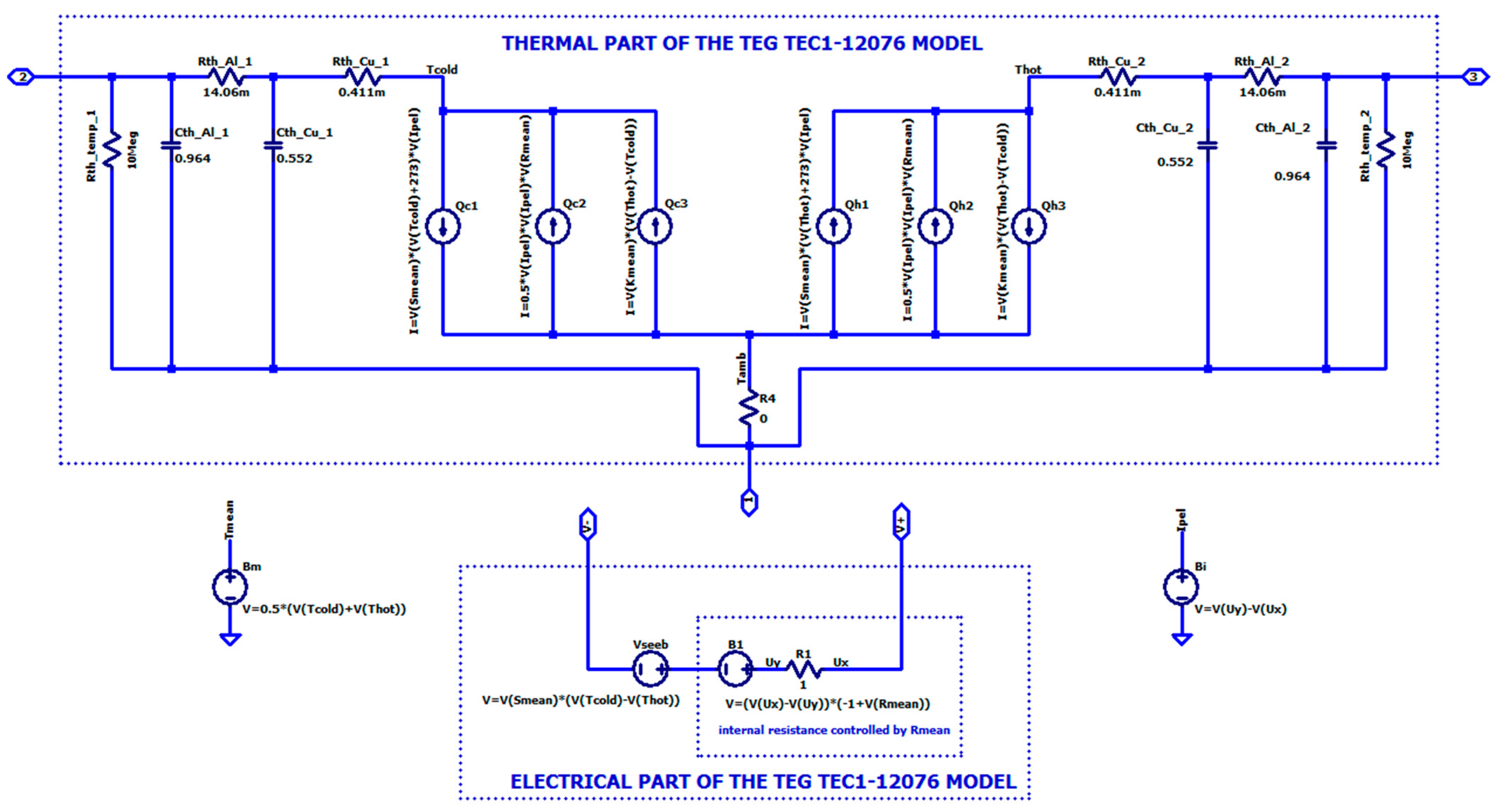
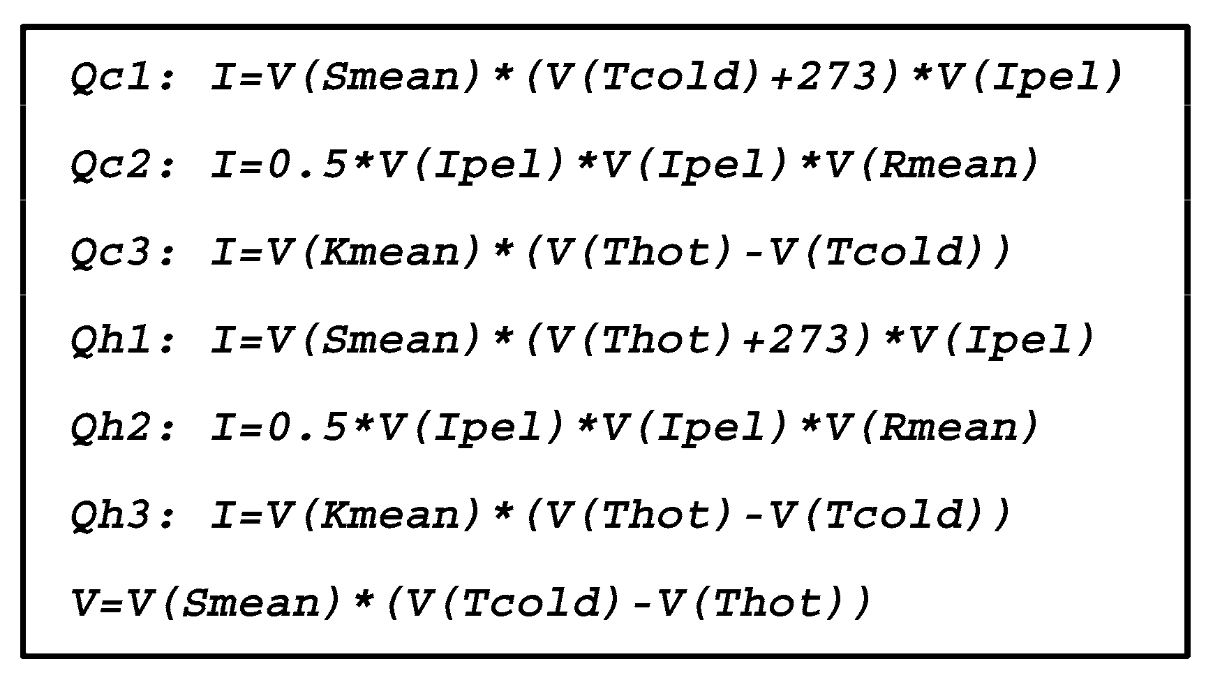
2.2. Electro-Thermal Analogy-Based TEG Model
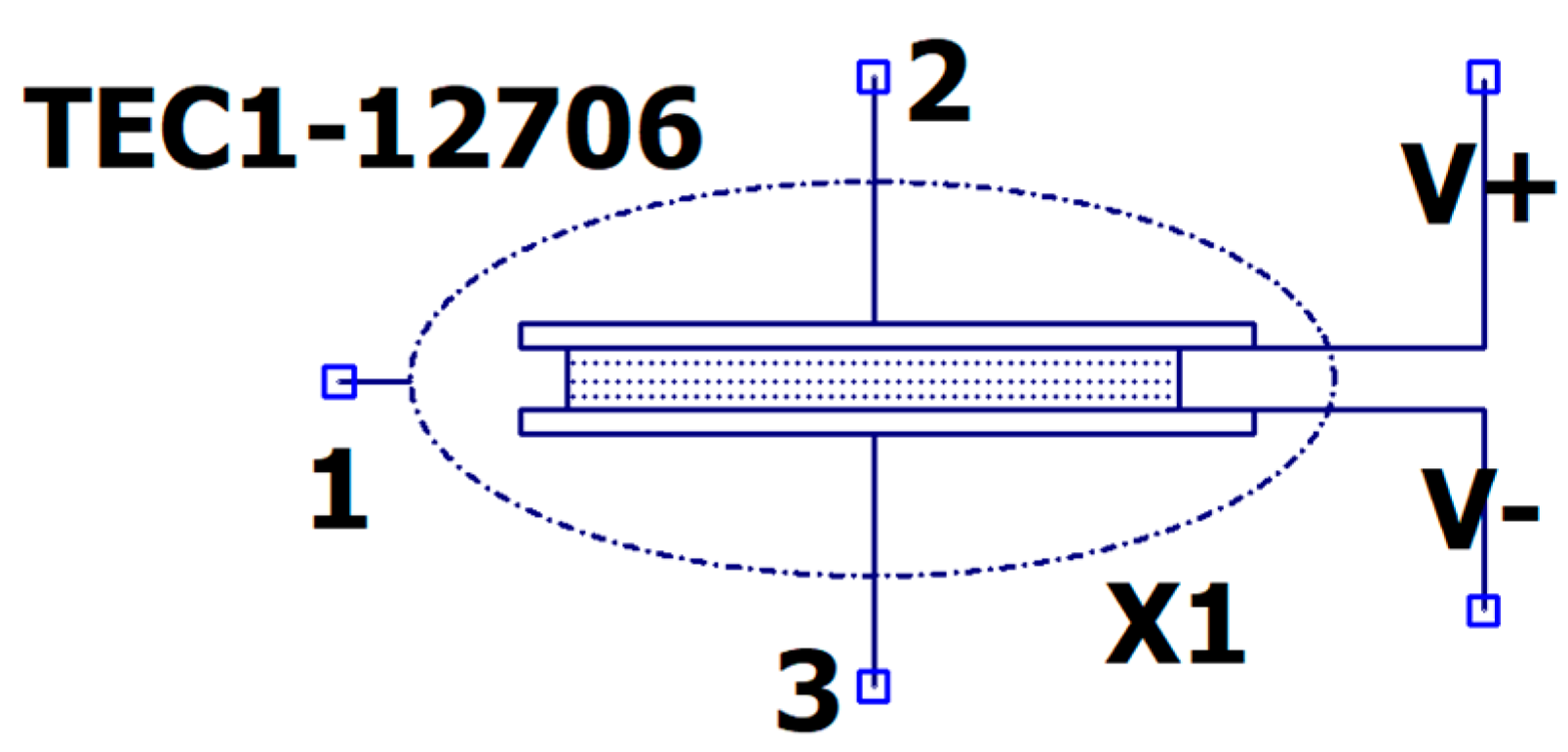
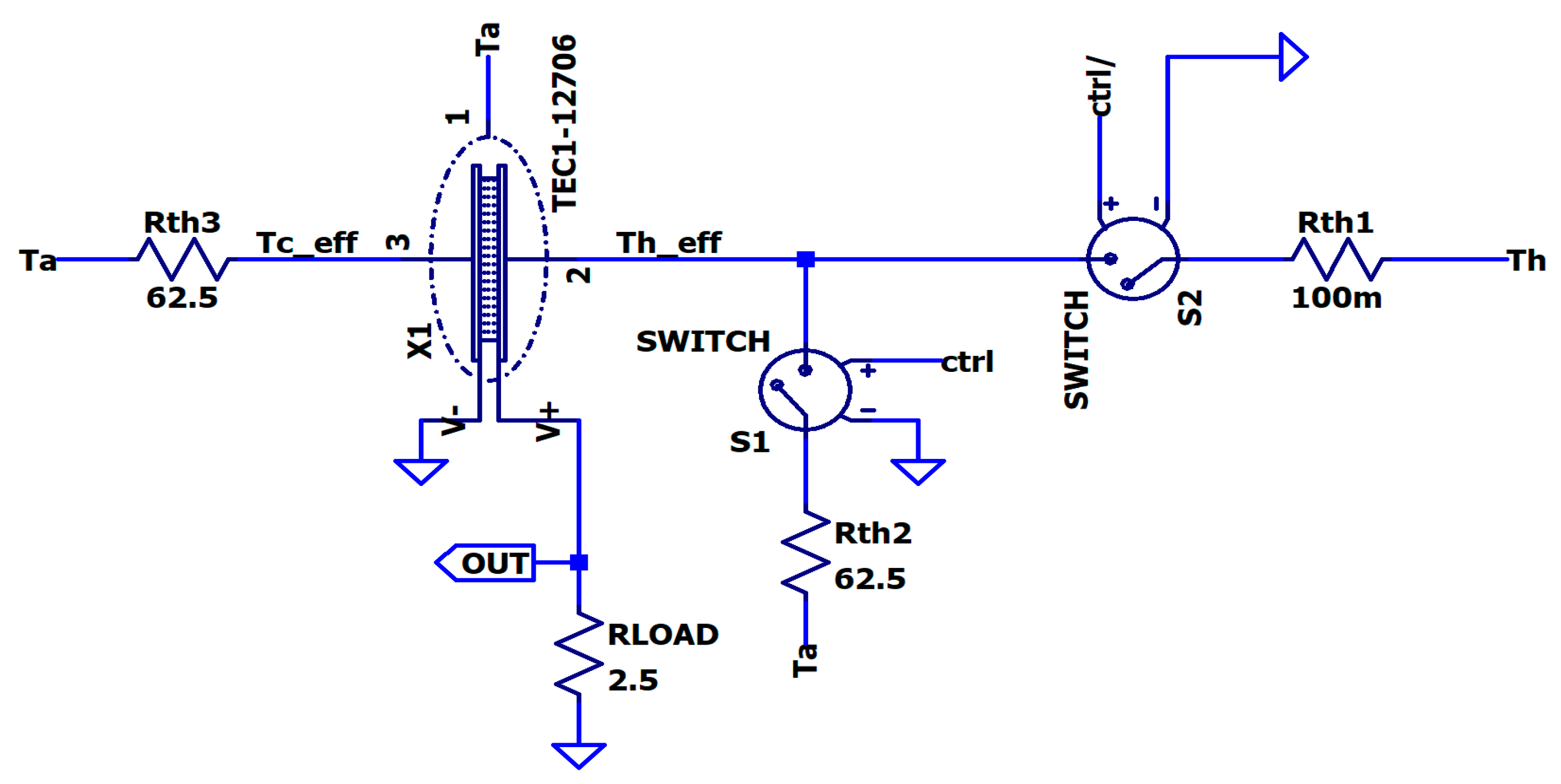
2.3. Electrothermal Model of a TEG Based on the Low-Cost Themoelectric Module TEC1-12706
3. Simulated Basic Operations of the TEG and Performance Assessments
3.1. Seebeck Voltage in Open Circuit Mode of Operation
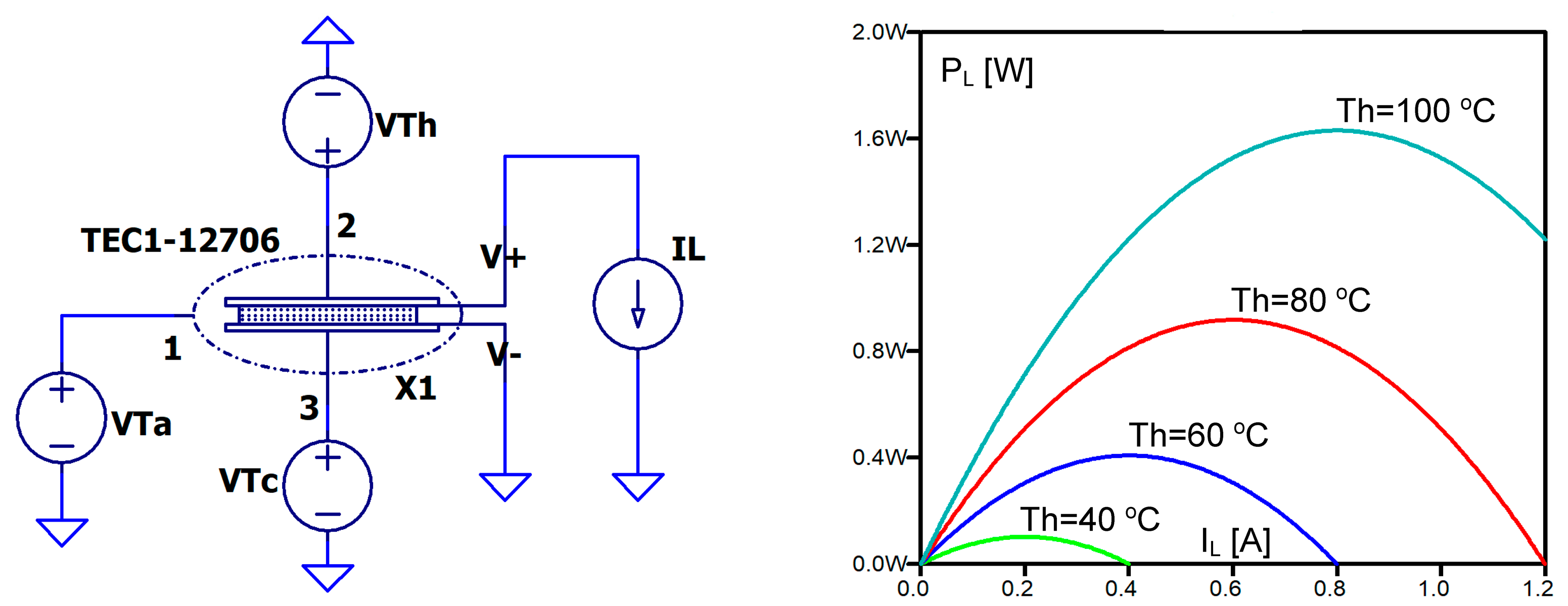
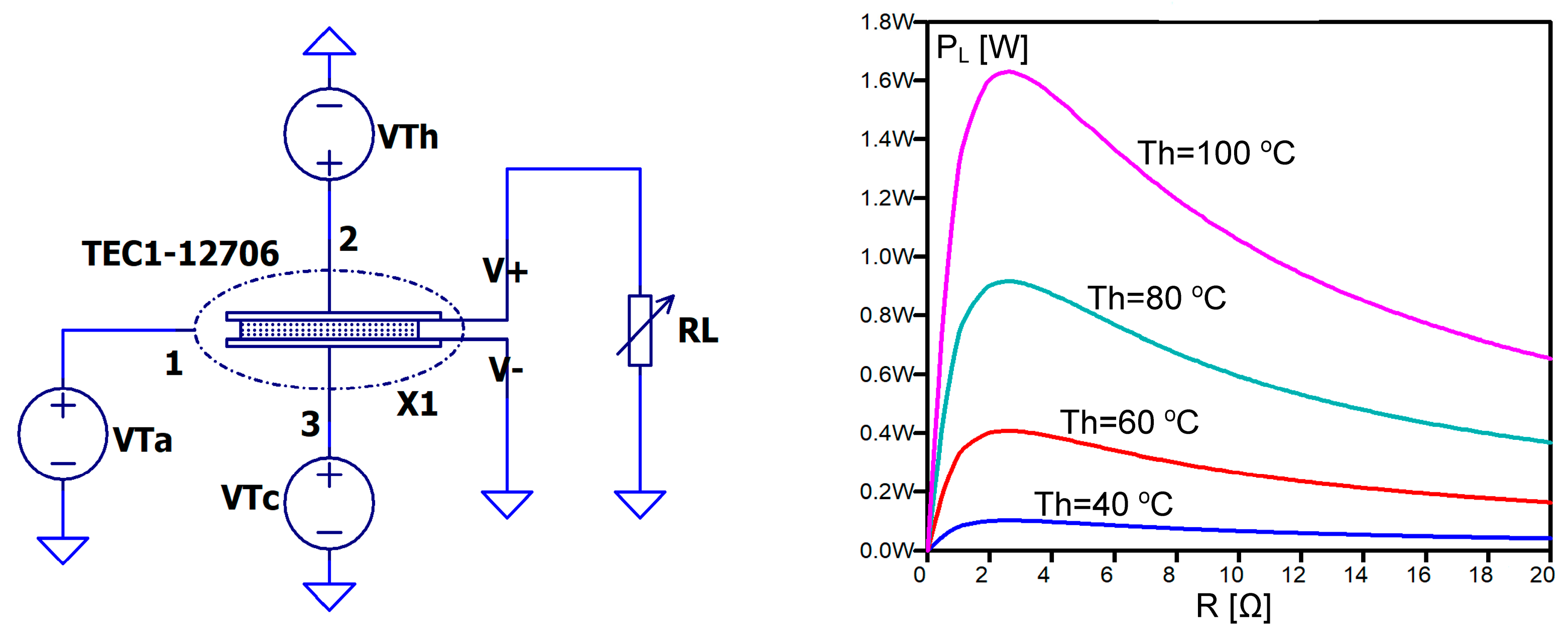
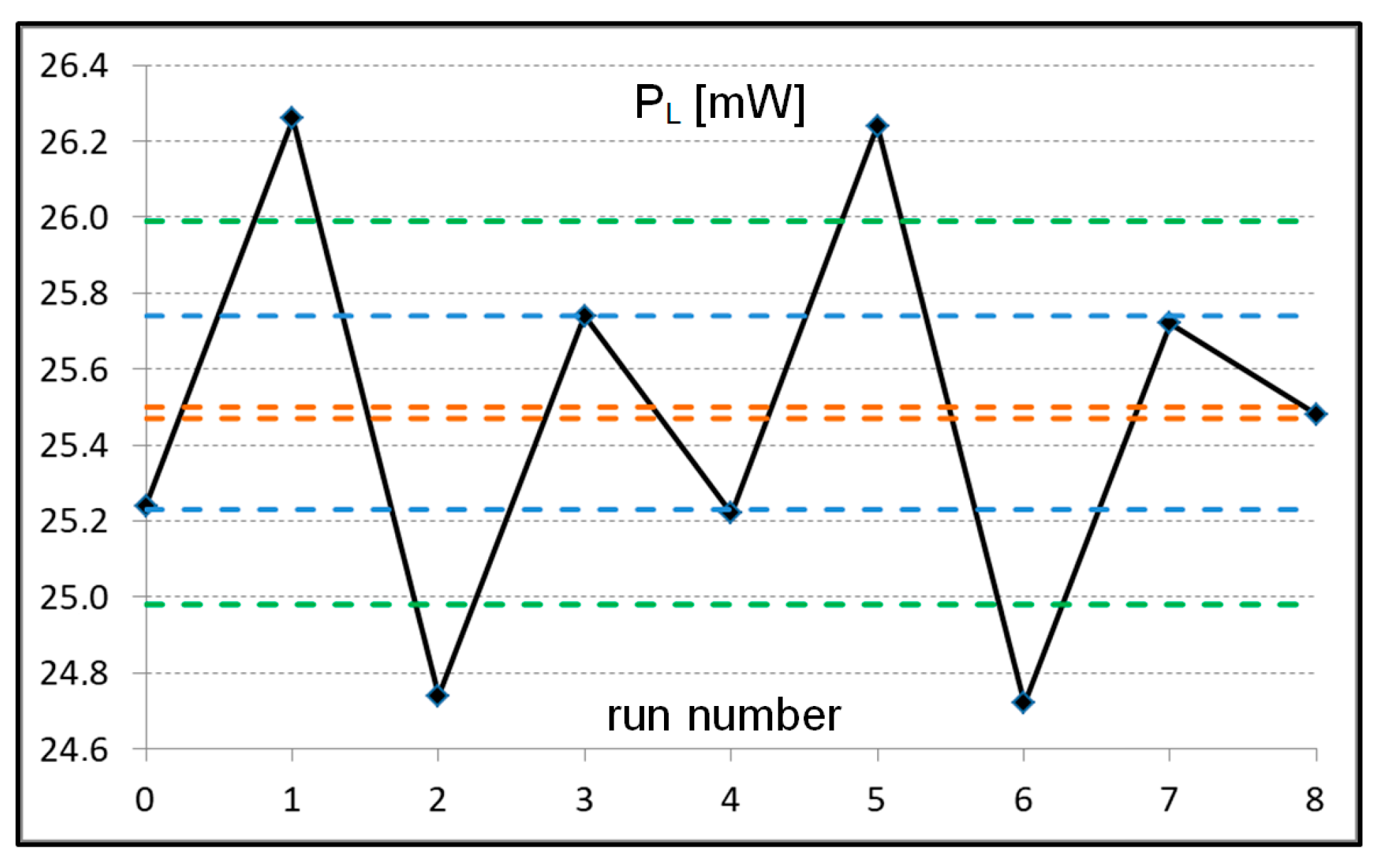
3.2. Maximum Available Output Power and Maximum Power Transfer Point
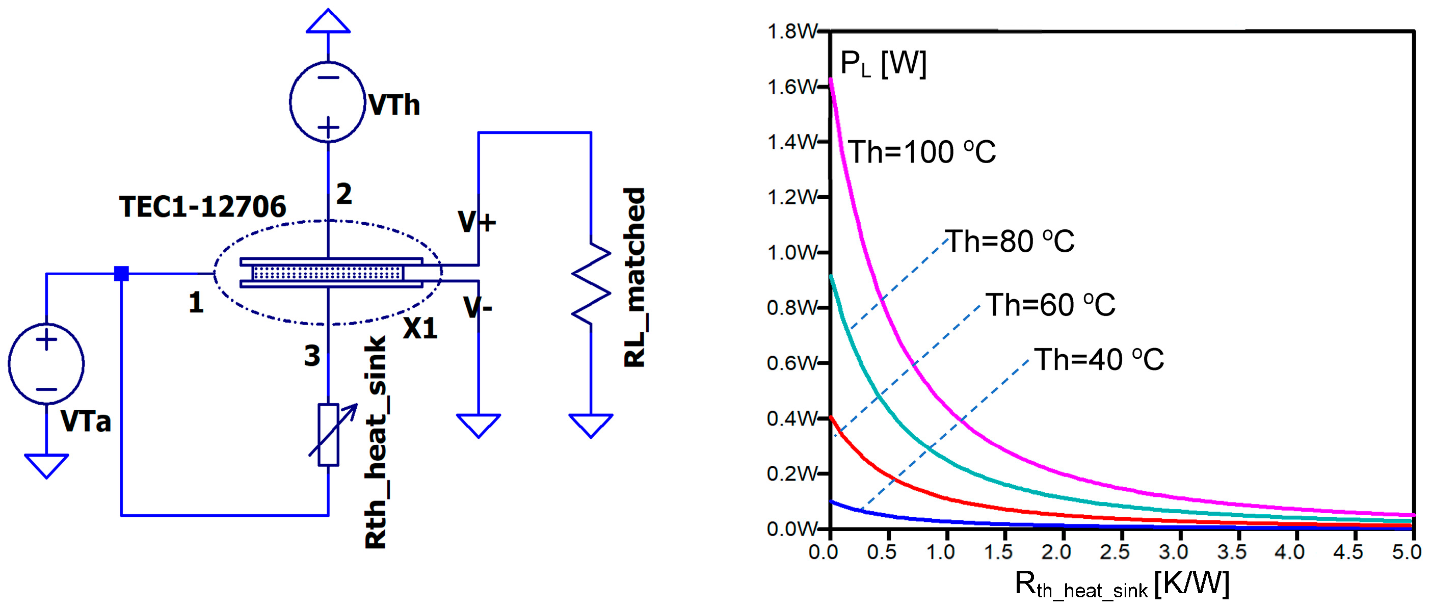
3.3. The Influence of the Thermal Resistance of a Heat Sink on Output Power
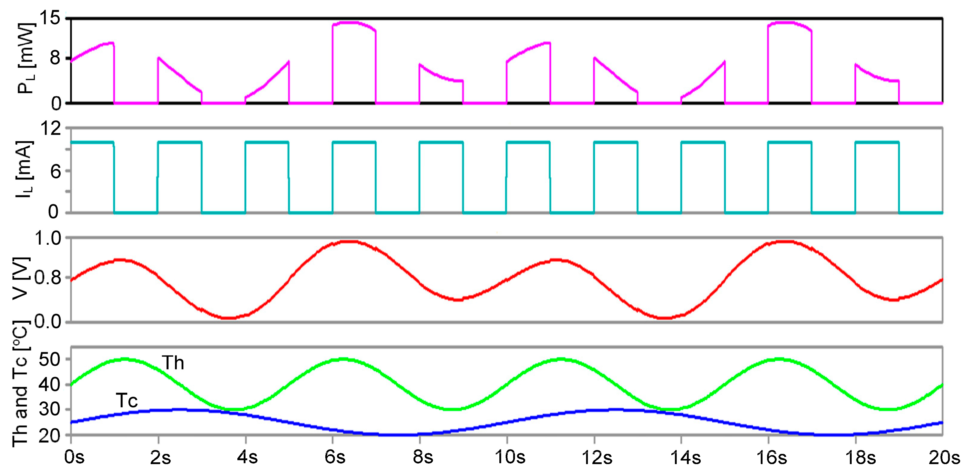
3.4. Operation of TEG under Varied Temperatures on Both Sides of the Thermoelectric Module and Electrical Load
3.5. Model’s Sensitivity to Key Material Parameter Deviations
4. Results of Numerical Simulations of Real Scenarios and Discussion
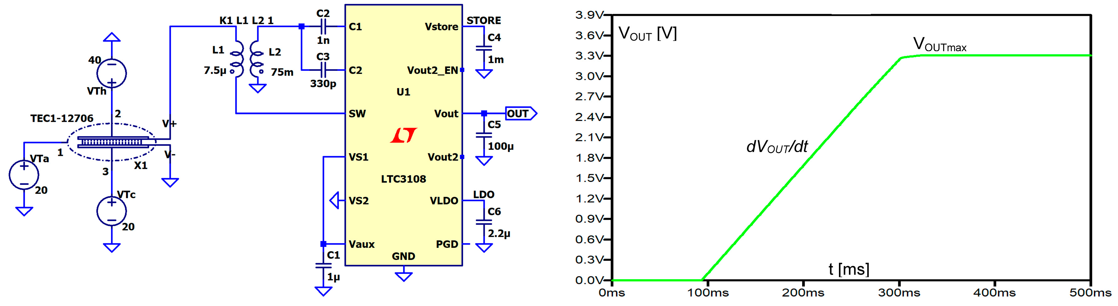
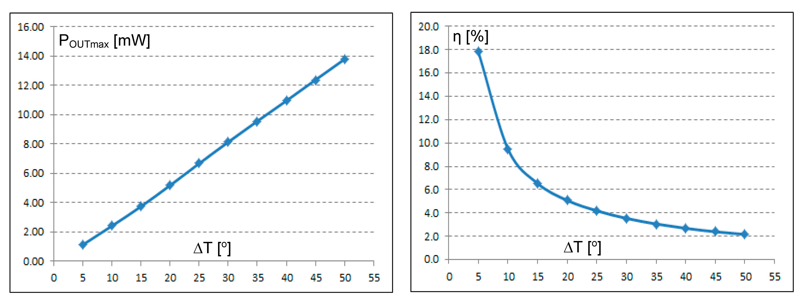
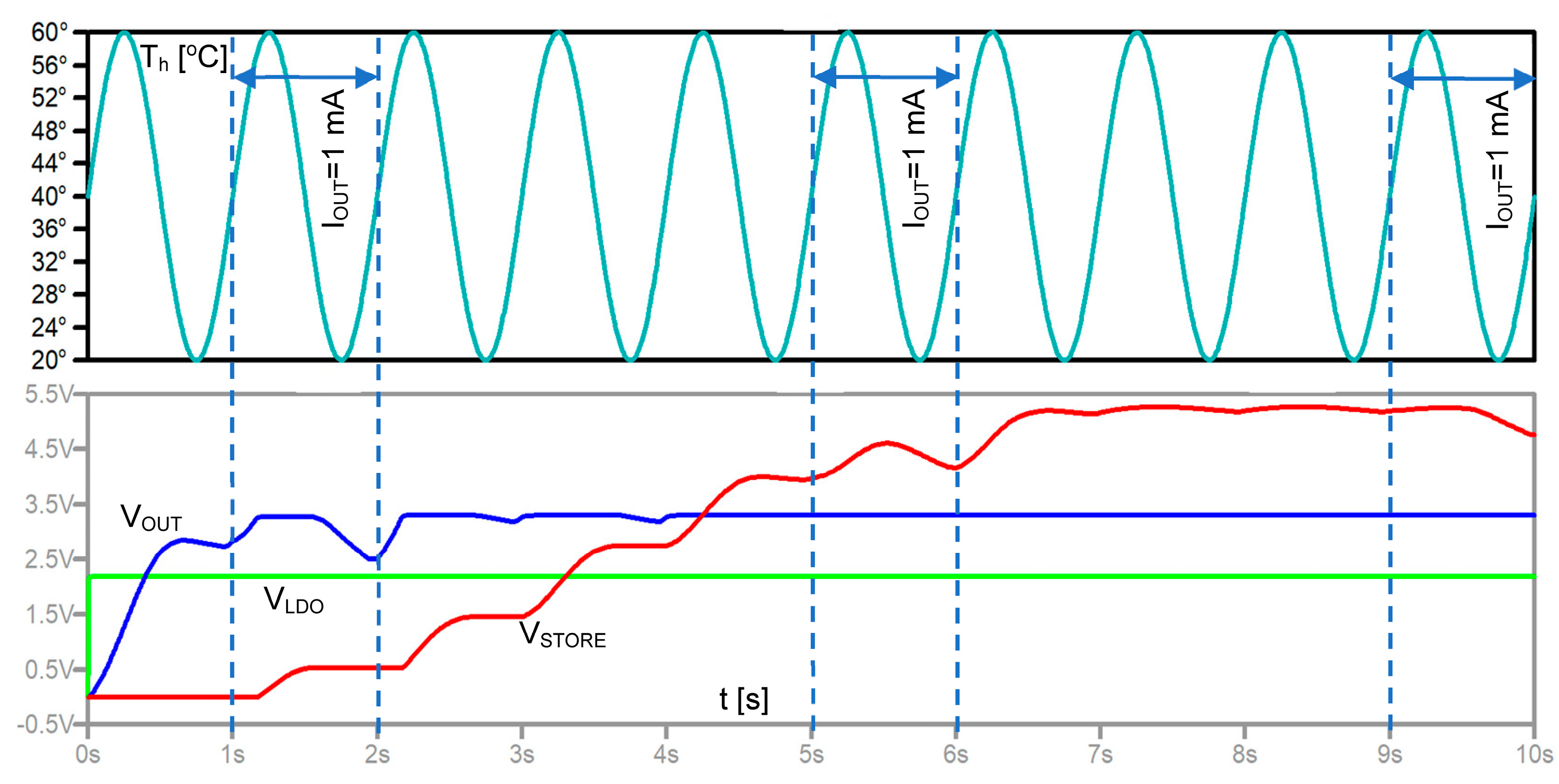
4.1. Combined Operation of a TEG and a Power Management Circuit
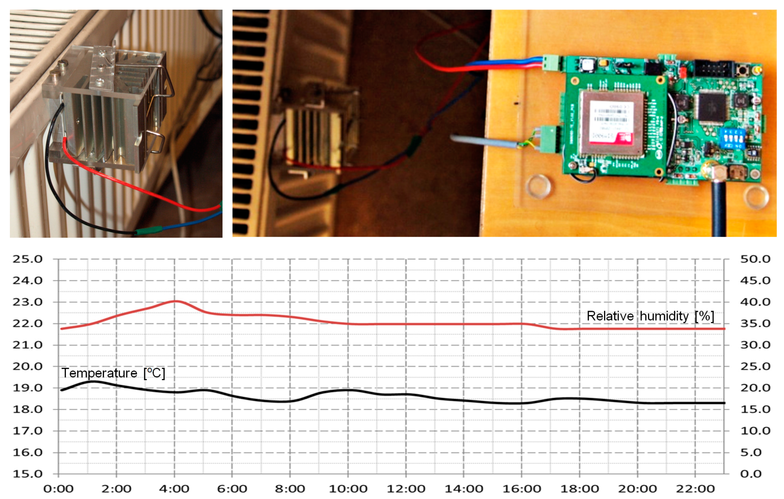
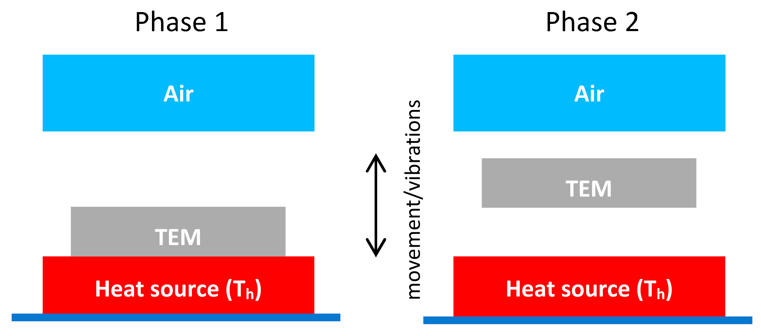
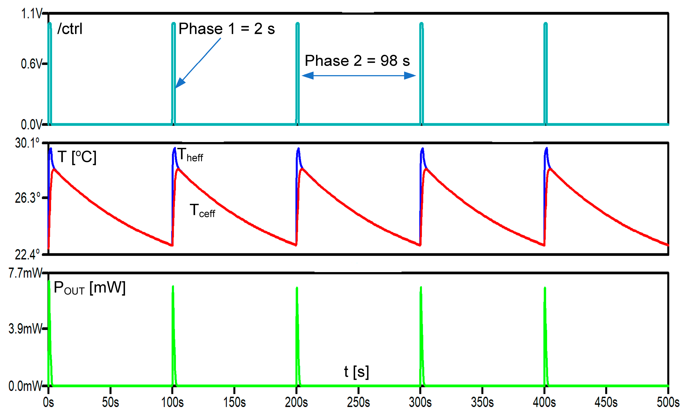
4.2. Termalization Effect and Pulsed Operation of TEG in Heat Sink-Less Energy Harvesting Applications
5. Conclusions
Author Contributions
Funding
Data Availability Statement
Acknowledgments
Conflicts of Interest
References
- Technavio Reports. Available online: https://www.technavio.com/ (accessed on 18 November 2023).
- State of IoT 2023: Number of Connected IoT Devices Growing 16% to 16.7 Billion Globally. Available online: https://iot-analytics.com/number-connected-iot-devices/ (accessed on 18 November 2023).
- Global IoT Connectivity Market Report and Forecast 2023–2028. Available online: www.researchandmarkets.com (accessed on 8 November 2023).
- United Nations, Department of Economic and Social Affairs, Population Division, World Population Prospects, United Nations. 2015. Available online: https://esa.un.org/unpd/wpp/Download/Standard/Population/ (accessed on 8 November 2023).
- Priya, S.; Inman, D.J. Energy Harvesting Technologies; Springer: New York, NY, USA, 2008; ISBN 978-0-387-76463-4. [Google Scholar]
- Joseph, A.D. Energy Harvesting Projects. IEEE Pervasive Comput. 2005, 4, 69–71. [Google Scholar] [CrossRef]
- Luo, J.; Chen, Y.; Tang, K.; Luo, J. Remote monitoring information system and its applications based on the Internet of Things. In Proceedings of the 2009 International Conference on Future BioMedical Information Engineering (FBIE), Sanya, China, 13–14 December 2009; pp. 482–485. [Google Scholar]
- Paradiso, J.A.; Starner, T. Energy Scavenging for Mobile and Wireless Electronics. IEEE Pervasive Comput. 2005, 4, 18–27. [Google Scholar] [CrossRef]
- Shore, A.; Roller, J.; Bergeson, J.; Hamadani, B.H. Indoor light energy harvesting for battery-powered sensors using small photovoltaic modules. Energy Sci. Eng. 2021, 9, 2036–2043. [Google Scholar] [CrossRef] [PubMed]
- Jabbar, H.; Jeong, T. Ambient Light Energy Harvesting and Numerical Modeling of Non-Linear Phenomena. Appl. Sci. 2022, 12, 2068. [Google Scholar] [CrossRef]
- Cumbajín, M.; Sánchez, P.; Núñez, M.; Gordón, C. Energy Harvesting System with Solar Panels to Supply Low Power Electronic Devices. IOP Conf. Ser. Earth Environ. Sci. 2023, 1141, 012008. [Google Scholar] [CrossRef]
- Wei, C.; Jing, X. A comprehensive review on vibration energy harvesting: Modelling and realization. Renew. Sustain. Energy Rev. 2017, 74, 1–18. [Google Scholar] [CrossRef]
- Jiang, J.; Liu, S.; Feng, L.; Zhao, D. A Review of Piezoelectric Vibration Energy Harvesting with Magnetic Coupling Based on Different Structural Characteristics. Micromachines 2021, 12, 436. [Google Scholar] [CrossRef]
- Kenzhekhanov, T.; Abduvali, D.; Kalimuldina, G.; Adair, D. Investigating the feasibility of energy harvesting using material work functions. Mater. Today Proc. 2022, 49, 2501–2505. [Google Scholar] [CrossRef]
- Kurt, E.; Issimova, A.; Medetov, B. A wide-band electromagnetic energy harvester. Energy 2023, 277, 127693. [Google Scholar] [CrossRef]
- Sabat, W.; Klepacki, D.; Kamuda, K.; Kuryło, K.; Jankowski-Mihułowicz, P. Efficiency Measurements of Energy Harvesting from Electromagnetic Environment for Selected Harvester Systems. Electronics 2023, 12, 4247. [Google Scholar] [CrossRef]
- Abdulwali, Z.S.A.; Alqahtani, A.H.; Aladadi, Y.T.; Alkanhal, M.A.S.; Al-Moliki, Y.M.; Aljaloud, K.; Alresheedi, M.T. A High-Performance Circularly Polarized and Harmonic Rejection Rectenna for Electromagnetic Energy Harvesting. Sensors 2023, 23, 7725. [Google Scholar] [CrossRef] [PubMed]
- Dziadak, B. Hybrid Optical and Thermal Energy Conversion System to Power Internet of Things Nodes. Energies 2023, 16, 7076. [Google Scholar] [CrossRef]
- Veloo, S.G.; Tiang, J.J.; Muhammad, S.; Wong, S.K. A Hybrid Solar-RF Energy Harvesting System Based on an EM4325-Embedded RFID Tag. Electronics 2023, 12, 4045. [Google Scholar] [CrossRef]
- Sodige, B.A.K.; Furuno, H.; Ngo, N.C.T.; Sugiyama, H.; Baba, M.; Niihara, K.; Nakayama, T. Improvement of Power Recovery by Applying a Multi-Pulse Electric Field in the Thermoelectric Cycle Power Generation Process with Pyroelectric Materials. Energies 2023, 16, 4728. [Google Scholar] [CrossRef]
- Wang, Y.; Wang, N.; Cao, X. From Triboelectric Nanogenerator to Hybrid Energy Harvesters: A Review on the Integration Strategy toward High Efficiency and Multifunctionality. Materials 2023, 16, 6405. [Google Scholar] [CrossRef] [PubMed]
- Kim, H.; Nguyen, D.C.; Luu, T.T.; Ding, Z.; Lin, Z.-H.; Choi, D. Recent Advances in Functional Fiber-Based Wearable Triboelectric Nanogenerators. Nanomaterials 2023, 13, 2718. [Google Scholar] [CrossRef] [PubMed]
- Dashevsky, Z.; Skipidarov, S. Investigating the Performance of Bismuth-Antimony Telluride. In Novel Thermoelectric Materials and Device Design Concepts; Springer International Publishing: Cham, Switzerland, 2019; pp. 3–21. ISBN 9783030120573. [Google Scholar]
- Zhang, Q.H.; Huang, X.Y.; Bai, S.Q.; Shi, X.; Uher, C.; Chen, L.D. Thermoelectric Devices for Power Generation: Recent Progress and Future Challenges. Adv. Eng. Mater. 2016, 18, 194–213. [Google Scholar] [CrossRef]
- Shi, X.L.; Zou, J.; Chen, Z.G. Advanced Thermoelectric Design: From Materials and Structures to Devices. Chem. Rev. 2020, 120, 7399–7515. [Google Scholar] [CrossRef]
- Yan, Q.; Kanatzidis, M.G. High-performance thermoelectrics and challenges for practical devices. Nat. Mater. 2022, 21, 503–513. [Google Scholar] [CrossRef]
- Shtern, Y.; Sherchenkov, A.; Shtern, M.; Rogachev, M.; Pepelyaev, D. Challenges and perspective recent trends of enhancing the efficiency of thermoelectric materials on the basis of PbTe. Mater. Today Commun. 2023, 37, 107083. [Google Scholar] [CrossRef]
- Spies, P.; Mateu, L.; Pollak, M. Handbook of Energy Harvesting Power Supplies and Applications; CRC Press, Taylor & Francis Group: Boca Raton, FL, USA, 2013. [Google Scholar]
- Rowe, D.M. Thermoelectrics Handbook Macro to Nano; CRC Press/Taylor & Francis Group: Boca Raton, FL, USA, 2006. [Google Scholar]
- Duong, A.T.; Nguyen, V.Q.; Duvjir, G.; Duong, V.T.; Kwon, S.; Song, J.Y.; Lee, J.K.; Lee, J.E.; Park, S.; Min, T.; et al. Achieving ZT¼2.2 with Bi-doped ntype SnSe single crystals. Nat. Commun. 2016, 7, 13713. [Google Scholar] [CrossRef] [PubMed]
- Zhao, L.-D.; Lo, S.-H.; Zhang, Y.; Sun, H.; Tan, G.; Uher, C.; Wolverton, C.; Dravid, V.P.; Kanatzidis, M.G. Ultralow thermal conductivity and high thermoelectric figure of merit in SnSe crystals. Nature 2014, 508, 373–377. [Google Scholar] [CrossRef] [PubMed]
- Estakhri, N.M.; Edwards, B.; Engheta, N. Inverse-designed metastructures that solve equations. Science 2019, 363, 1333–1338. [Google Scholar] [CrossRef]
- Lalegani, Z.; Seyyed Ebrahimi, S.A.; Hamawandi, B.; La Spada, L.; Batili, H.; Toprak, M.S. Targeted dielectric coating of silver nanoparticles with silica to manipulate optical properties for metasurface applications. Mater. Chem. Phys. 2022, 287, 126250. [Google Scholar] [CrossRef]
- Pacheco-Peña, V.; Beruete, M.; Rodríguez-Ulibarri, P.; Engheta, N. On the performance of an ENZ-based sensor using transmission line theory and effective medium approach. New J. Phys. 2019, 21, 043056. [Google Scholar] [CrossRef]
- Akbari, M.; Shahbazzadeh, M.J.; La Spada, L.; Khajehzadeh, A. The Graphene Field Effect Transistor Modeling Based on an Optimized Ambipolar Virtual Source Model for DNA Detection. Appl. Sci. 2021, 11, 8114. [Google Scholar] [CrossRef]
- Greybush, N.J.; Pacheco-Peña, V.; Engheta, N.; Murray, C.B.; Kagan, C.R. Plasmonic Optical and Chiroptical Response of Self-Assembled Au Nanorod Equilateral Trimers. ACS Nano 2019, 13, 1617–1624. [Google Scholar] [CrossRef]
- Lincoln, R.L.; Scarpa, F.; Ting, V.P.; Trask, R.S. Multifunctional composites: A metamaterial perspective. Multifunct. Mater. 2019, 2, 043001. [Google Scholar] [CrossRef]
- Ouyang, Z.; Li, D. Modelling of segmented high-performance thermoelectric generators with effects of thermal radiation, electrical and thermal contact resistances. Sci. Rep. 2016, 6, 24123. [Google Scholar] [CrossRef]
- Olivares-Robles, M.A.; Badillo-Ruiz, C.A.; Ruiz-Ortega, P.E. A comprehensive analysis on nanostructured materials in a thermoelectric micro-system based on geometric shape, segmentation structure and load resistance. Sci. Rep. 2020, 10, 21659. [Google Scholar] [CrossRef]
- LTC3108 Datasheet and Product Info|Analog Devices. Available online: https://www.analog.com/media/en/technical-documentation/data-sheets/LTC3108.pdf (accessed on 3 November 2023).
- Zhang, P.; Liu, L. A Photovoltaic and Thermal Energy Combining Harvesting Interface Circuit with MPPT and Single Inductor. In Proceedings of the 2020 IEEE 15th International Conference on Solid-State & Integrated Circuit Technology (ICSICT), Kunming, China, 3–6 November 2020; pp. 1–3. [Google Scholar] [CrossRef]
- Tang, Y.-W.; Wong, C.-H.; Du, Y.; Du, L.; Li, Y.; Chang, M.-C.F. A fully integrated 28nm CMOS dual source adaptive thermoelectric and RF energy harvesting circuit with 110mv startup voltage. In Proceedings of the 2018 IEEE Custom Integrated Circuits Conference (CICC), San Diego, CA, USA, 8–11 April 2018; pp. 1–4. [Google Scholar] [CrossRef]
- Veri, C.; Francioso, L.; Pasca, M.; De Pascali, C.; Siciliano, P.; D’Amico, S. An 80 mv startup voltage fully electrical DC–DC converter for flexible thermoelectric generators. IEEE Sens. J. 2016, 16, 2735–2745. [Google Scholar] [CrossRef]
- Mateu, L.; Codrea, C.; Lucas, N.; Pollak, M.; Spies, P. Human Body Energy Harvesting Thermogenerator for Sensing Applications. In Proceedings of the International Conference on Sensor Technologies and Applications (SENSORCOMM 2007), Valencia, Spain, 14–20 October 2007; pp. 366–372. [Google Scholar]
- Deng, F.; Qiu, H.; Chen, J.; Wang, L.; Wang, B. Wearable thermoelectric power generators combined with flexible supercapacitor for low-power human diagnosis devices. IEEE Trans. Ind. Electron. 2016, 64, 1477–1485. [Google Scholar] [CrossRef]
- Skotnicki, T. Energy Harvesting for IoT. 2015. Available online: http://www.vlsisymposium.org/Past/15web/technology.html (accessed on 18 November 2023).
- LTspice. Available online: https://www.analog.com/en/design-center/design-tools-and-calculators/ltspice-simulator.html (accessed on 18 November 2023).
- Dalola, S.; Ferrari, M.; Ferrari, V.; Guizzetti, D.M.; Taroni, A. Characterization of Thermoelectric Modules for Powering Autonomous Sensors. IEEE Trans. Instrum. Meas. 2009, 58, 99–107. [Google Scholar] [CrossRef]
- Seifert, W.; Ueltzen, M.; Strumpel, C.; Heiliger, W.; Muller, E. One-dimensional modeling of a Peltier element. In Proceedings of the ICT2001. 20 International Conference on Thermoelectrics (Cat. No. 01TH8589), Beijing, China, 8–11 June 2001; pp. 439–443. [Google Scholar] [CrossRef]
- Seetawan, T.; Seetawan, U.; Ratchasin, A.; Srichai, S.; Singsoog, K.; Namhongsa, W.; Ruttanapun, C.; Siridejachai, S. Analysis of Thermoelectric Generator by Finite Element Method. Procedia Eng. 2012, 32, 1006–1011. [Google Scholar] [CrossRef]
- Wielgosz, S.E.; Clifford, C.E.; Yu, K.; Barry, M.M. Fully–coupled thermal–electric modeling of thermoelectric generators. Energy 2023, 266, 126324. [Google Scholar] [CrossRef]
- Wu, G.; Yu, X. A holistic 3D finite element simulation model for thermoelectric power generator element. Energy Convers. Manag. 2014, 86, 99–110. [Google Scholar] [CrossRef]
- Lineykin, S.; Ben-Yaakov, S. Analysis of thermoelectric coolers by a spice-compatible equivalent-circuit model. IEEE Power Electron. Lett. 2005, 3, 63–66. [Google Scholar] [CrossRef]
- Dziurdzia, P.; Kos, A. Electrothermal Macromodel of Active Heat Sink for Cooling Process Simulation. In Proceedings of the 5th International Workshop on Thermal Investigations of Ics and Microstructures, Rome, Italy, 3–6 October1999; pp. 76–81. [Google Scholar]
- Dziurdzia, P.; Kos, A. Tool for fast modelling active heat sinks. In Proceedings of the XVIIth Annual IEEE Semiconductor Thermal Measurement and Management Symposium SEMITHERM, San Jose, CA, USA, 20–22 March 2001; pp. 174–179. [Google Scholar]
- Mitrani, D.; Salazar, J.; Turo, A.; Garcia, M.J.; Chavez, J.A. Lumped and Distributed Parameter SPICE Models of TE Devices Considering Temperature Dependent Material Properties. In Proceedings of the 13th International Workshop on Thermal Investigations of ICs and Systems, Budapest, Hungary, 17–19 September 2007; pp. 202–207. [Google Scholar]
- Lineykin, S.; Ben-Yaakov, S. SPICE Compatible Equivalent Circuit of the Energy Conversion Processes in Thermoelectric Modules. In Proceedings of the 23rd IEEE Convention of Electrical and Electronics Engineers in Israel, Tel-Aviv, Israel, 6–7 September 2004. [Google Scholar]
- Mirocha, A.; Dziurdzia, P. Improved electrothermal model of the thermoelectric generator implemented in SPICE. In Proceedings of the International Conference on Signals and Electronic Systems, Cracow, Poland, 14–17 September 2008; pp. 317–320. [Google Scholar]
- Chen, M.; Rosendahl, L.A.; Condra, T.J.; Pedersen, J.K. Numerical Modeling of Thermoelectric Generators With Varing Material Properties in a Circuit Simulator. IEEE Trans. Energy Convers. 2009, 24, 112–124. [Google Scholar] [CrossRef]
- Markiewicz, M.; Dziurdzia, P.; Konieczny, T.; Skomorowski, M.; Kowalczyk, L.; Skotnicki, T.; Urard, P. Software Controlled Low Cost Thermoelectric Energy Harvester for Ultra-Low Power Wireless Sensor Nodes. IEEE Access 2020, 8, 38920–38930. [Google Scholar] [CrossRef]
- Mitrani, D.; Tome, J.A.; Salazar, J.; Turo, A.; Garcia, M.J.; Chavez, J.A. Methodology for extracting thermoelectric module parameters. IEEE Trans. Instrum. Meas. 2005, 54, 1548–1552. [Google Scholar] [CrossRef]
- Dziurdzia, P. Measurement Setup for Characterization of Peltier Modules used as Micro Thermoelectric Generators in Smart Wireless Sensor Networks. In Proceedings of the XXXI International Conference of International Microelectronics and Packaging Society Poland Chapter, Rzeszów-Krasiczyn, Poland, 23–26 September 2007; pp. 311–314. [Google Scholar]
- Dziurdzia, P.; Bratek, P.; Brzozowski, I.; Gelmuda, W.; Ostrowski, J.; Kos, A. Extraction of temperature dependent parameters for an electrothermal model of thermoelectric energy harvester. In Proceedings of the 2016 MIXDES—23rd International Conference Mixed Design of Integrated Circuits and Systems, Lodz, Poland, 23–25 June 2016; pp. 377–381. [Google Scholar] [CrossRef]
- Salerno, D. Ultralow Voltage Energy Harvester Uses Thermoeletric Generator for Battery-free Wireless Sensors. LT J. 2005, 20, 1–11. Available online: https://www.analog.com/media/en/technical-documentation/lt-journal-article/ltjournal-v20n3-01-df-ltc3108_09-david_salerno.pdf (accessed on 18 November 2023).
- Afghan, S.A.; Géza, H. Modelling and Analysis of Energy Harvesting in Internet of Things (IoT): Characterization of a Thermal Energy Harvesting Circuit for IoT based Applications with LTC3108. Energies 2019, 12, 3873. [Google Scholar] [CrossRef]
- Haras, M.; Markiewicz, M.; Monfray, S.; Skotnicki, T. Pulse mode of operation—A new booster of TEG, improving power up to X2.7—To better fit IoT requirements. Nano Energy 2020, 68, 104204. [Google Scholar] [CrossRef]
- Dziurdzia, P. Thermoelectric Generator LTspice Model. Available online: https://github.com/piotrdziurdzia/teg (accessed on 14 November 2023).


| Rth_Cu [K/W] | Cth_Cu [J/K] | Rth_Al2O3 [K/W] | Cth_Al2O3 [J/K] | R [Ω] | S [mV/K] | K [mW/K] | |||
|---|---|---|---|---|---|---|---|---|---|
| a | b | a | b | a | b | ||||
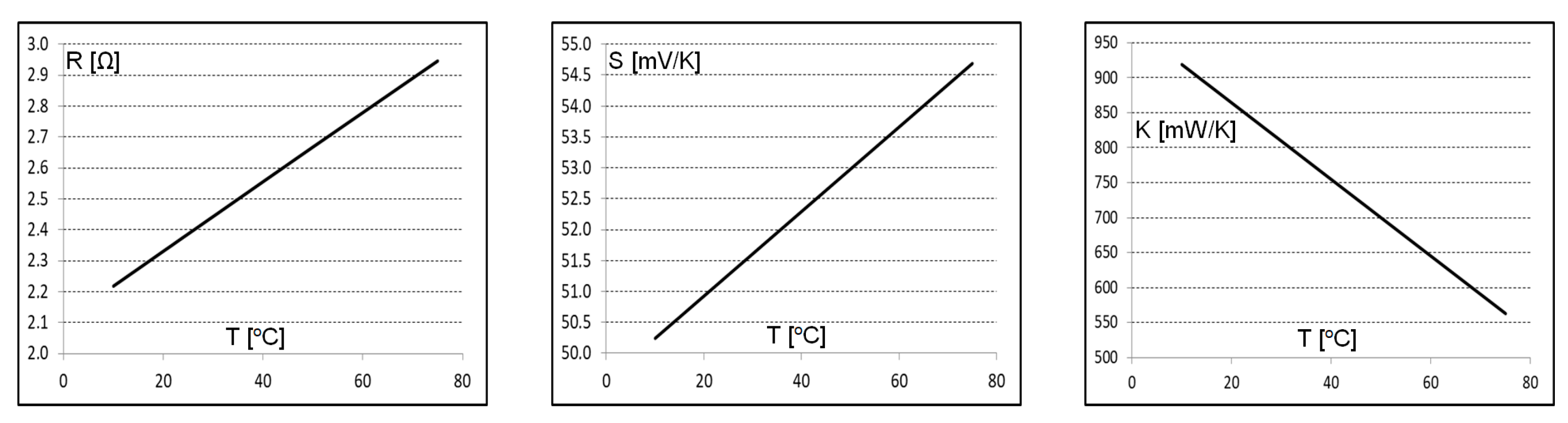
| 0.41 m | 0.55 | 14.06 m | 0.96 | 0.011 | 2.106 | 0.068 | 49.56 | −5.48 | 973.9 |
| ∆T [°] | dVOUT/dt [V/s] | POUTmax [mW] | η [%] |
|---|---|---|---|
| 5 | 3.44 | 1.14 | 17.8 |
| 10 | 7.34 | 2.42 | 9.5 |
| 15 | 11.36 | 3.75 | 6.5 |
| 20 | 15.72 | 5.19 | 5.1 |
| 25 | 20.25 | 6.68 | 4.2 |
| 30 | 24.66 | 8.14 | 3.5 |
| 35 | 28.97 | 9.56 | 3.1 |
| 40 | 33.20 | 10.96 | 2.7 |
| 45 | 37.52 | 12.38 | 2.4 |
| 50 | 41.79 | 13.79 | 2.2 |
Disclaimer/Publisher’s Note: The statements, opinions and data contained in all publications are solely those of the individual author(s) and contributor(s) and not of MDPI and/or the editor(s). MDPI and/or the editor(s) disclaim responsibility for any injury to people or property resulting from any ideas, methods, instructions or products referred to in the content. |
© 2023 by the authors. Licensee MDPI, Basel, Switzerland. This article is an open access article distributed under the terms and conditions of the Creative Commons Attribution (CC BY) license (https://creativecommons.org/licenses/by/4.0/).
Share and Cite
Dziurdzia, P.; Bratek, P.; Markiewicz, M. An Efficient Electrothermal Model of a Thermoelectric Converter for a Thermal Energy Harvesting Process Simulation and Electronic Circuits Powering. Energies 2024, 17, 204. https://doi.org/10.3390/en17010204
Dziurdzia P, Bratek P, Markiewicz M. An Efficient Electrothermal Model of a Thermoelectric Converter for a Thermal Energy Harvesting Process Simulation and Electronic Circuits Powering. Energies. 2024; 17(1):204. https://doi.org/10.3390/en17010204
Chicago/Turabian StyleDziurdzia, Piotr, Piotr Bratek, and Michał Markiewicz. 2024. "An Efficient Electrothermal Model of a Thermoelectric Converter for a Thermal Energy Harvesting Process Simulation and Electronic Circuits Powering" Energies 17, no. 1: 204. https://doi.org/10.3390/en17010204
APA StyleDziurdzia, P., Bratek, P., & Markiewicz, M. (2024). An Efficient Electrothermal Model of a Thermoelectric Converter for a Thermal Energy Harvesting Process Simulation and Electronic Circuits Powering. Energies, 17(1), 204. https://doi.org/10.3390/en17010204