Abstract
Implementation of renewable energy sources (RESs) in power systems can reduce the dependence on fossil-fuel-based thermal power generation systems. At the same time, however, the system inertia decreases as synchronous generators decrease; this is crucial for maintaining the stability of the power system. Virtual inertia control (VIC) can regulate the output of an inverter-based resource (IBR) by increasing the inertia. For a wind turbine generator (WTG), output control factors such as pitch angle control and maximum power point tracking (MPPT) significantly affect the performance of the VIC. This paper theoretically clarifies that the pitch angle control contributes to improvements in the performance of the VIC and helps avoid a loss of operation of the WTG in frequency drop events by analyzing the movement of the operational point of the WTG based on the physical characteristic of the WTG and control characteristics of the pitch angle control and MPPT; an electromagnetic transient (EMT) simulation, performed to verify the analysis, is also presented.
1. Introduction
Renewable energy sources (RESs) are being increasingly implemented into power grids to realize sustainable energy generation systems. Photovoltaic generators (PVs) and Type III and IV wind turbine generators (WTGs) are typically connected to the grid via inverters. These inverter-based resources (IBRs) can help reduce the usage of fossil-fuel-based thermal power generators; however, they decrease system inertia. Low-inertia systems are vulnerable to disturbances, which can reduce the stability of the power supply. Consequently, virtual inertia control (VIC), which emulates the behavior of a machine or generator with rotational inertia in an IBR, was proposed to increase inertia [1,2].
VIC can be theoretically applied to the inverter to establish the grid connection of the IBR regardless of the type of DC-side power source (e.g., battery energy storage, PV, and WTG). However, the performance of the VIC partially deteriorates when it is implemented in PVs and WTGs based on the operating condition and the structure of the control system.
For WTGs, there are two types of VIC implementations without additional energy storage. The first is a combination with the de-loading operation [3,4]. Typically, the output of the WTG is maximized according to the wind conditions such that it does not exceed the rated output. Consequently, the output cannot be increased for an inertial response emulation by the VIC. De-loading (i.e., the intended decrease in output) can be implemented to accommodate for the increasing output. The acceleration and deceleration of the wind turbine (WT) and an increase in the pitch angle of the blades are effective means of achieving headroom. The pitch angle control is adopted for primary frequency control reserve from [5], and for the headroom for droop-based grid-forming control from [6]. The hybrid methodology of over-speeding and pitch angle control is also proposed in [7,8]. In these implementations, the VIC can change the WTG output within the reserved capacity, and its effectiveness is expected to be equivalent to that of the VIC embedded in the battery energy storage for disturbances despite the decrease in the capacity ratio of the WTG.
The second type of implementation involves temporarily using the stored energy in the WT and capacitor in the DC-link for the inertial response emulation. The release of the stored energy decreases the rotating frequency of the WT and DC-link voltage and ultimately leads to the loss of operation. To avoid this, the process of recovering the energy loss must be driven after the VIC response. In [9,10], the WTG output is controlled to decrease the stepwise after the output increase by VIC with a pre-determined time constant. Ref. [11] adopts ramp change in the output decrease. In [12], the output decrease for the recovering is triggered by a specified magnitude of decrease in the rotating frequency. The recovery of the operational condition of WTG can be obtained owing to the controllers typically embedded in the WTG, maximum power point tracking (MPPT), and pitch angle control. Since the behavior of these controllers depends on the wind condition, the recovery process also depends on it. The control system of the WTG is divided into four modes based on the wind condition as Regions 1–4 [13,14,15];
- −
- Region 1: Stopped (Wind speed is lower than the cut-in wind speed),
- −
- Region 2: MPPT operation (Wind speed is between the cut-in and rated wind speed),
- −
- Region 3 Rated output operation (Wind speed is between the rated and cut-out wind speed),
- −
- Region 4: Stopped (Wind speed is larger than the cut-out wind speed).
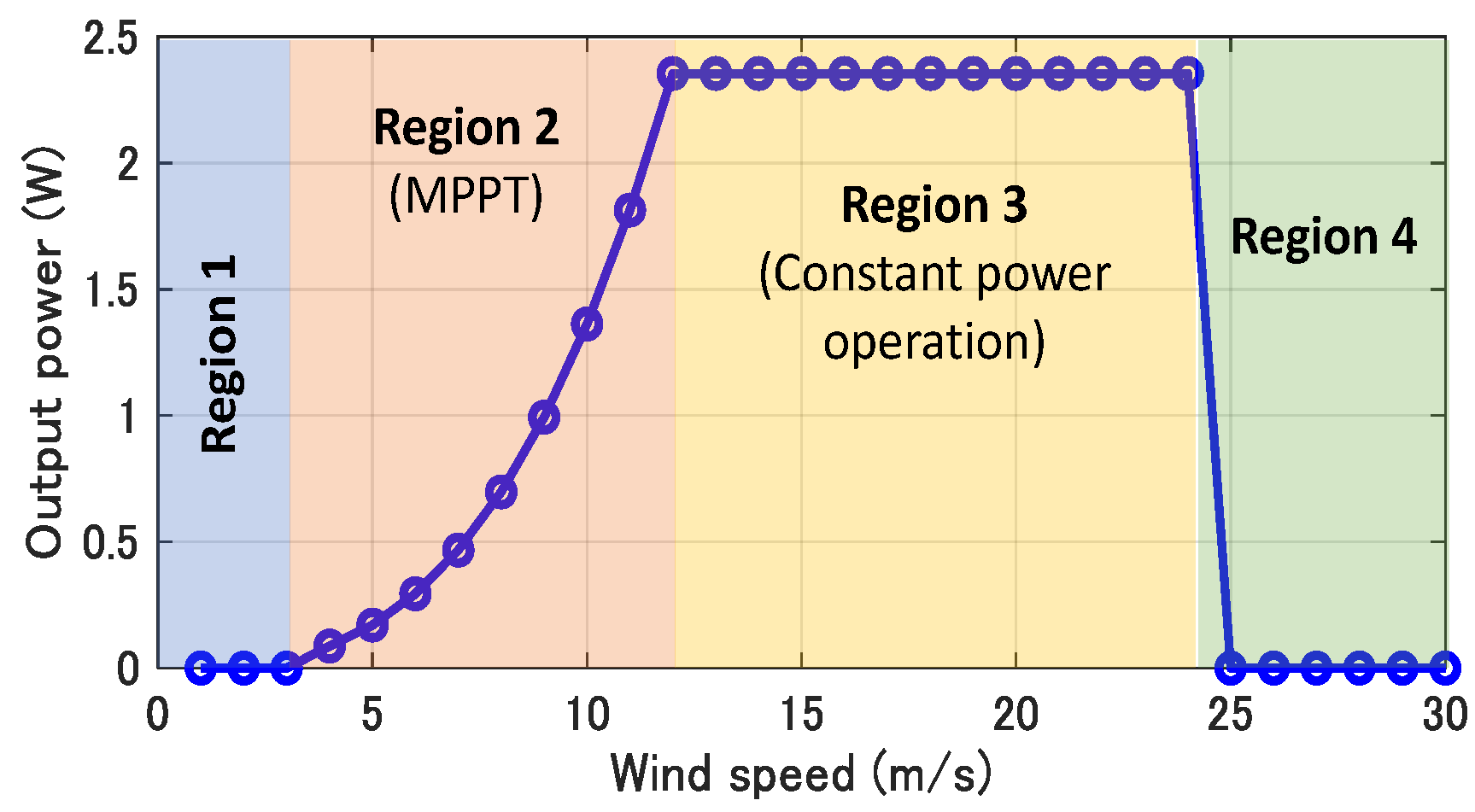
The WTG does not generate power when the wind speed is less than the cut-in wind speed (Region 1) or larger than the cut-out wind speed (Region 4). In Region 2, where the wind speed is greater than the cut-in value and smaller than the rated value, the output of the WTG is maximized by the MPPT. Lastly, in Region 3, the wind speed lies between the rated value and cut-out value, where the output and rotating frequency of the WT is maintained at the rated values by adjusting the pitch angle. The MPPT and the pitch angle controller are functions holding the operational point (i.e., the output and rotating frequency of the WT) at a specified point under a certain wind speed. Therefore, they can help in returning the operation state of the WTG to the nominal state after the VIC responds to the disturbance.
In Region 2, the MPPT helps in the recovery of the operational state. The active power reference is switched from the VIC to MPPT when the rotating frequency of the WT drops to the specified value in [16]. In [17,18], the active power reference is gradually changed to MPPT depending on the rotating frequency. In [19], the active power reference of the VIC is given as the MPPT curve increased by the amount of the inertial response to be emulated. In the VIC proposed in [20,21], the MPPT recovers the operation state after the VIC supplies the inertial response without switching, owing to the difference in the time constant between the VIC and MPPT. In [22,23,24], the DC-link voltage control recovers the energy released from the DC-link capacitance by inertial response emulation. Refs. [25,26] propose the hybrid method that MPPT and DC-link voltage control contribute to the recovery. The recovery process possibly deteriorates the performance of the VIC since it cancels out the output change produced by the VIC to compensate for the loss of energy. Ref. [20] demonstrates that increasing the time constant in MPPT such that it does not lead to the loss of operation can effectively improve the frequency regulation capability of the VIC. However, the criteria required to ensure the success of the recovery process have not been demonstrated thus far.
The recovery process in Region 3 varies from that in Region 2. The energy released from the WT is compensated by increasing the energy captured from the wind by decreasing the pitch angle. The performance of the VIC is not expected to deteriorate significantly since the change in the output of the WTG produced by the VIC does not need to be pulled back rapidly. However, previous studies conducted in this field have not analyzed the influence of pitch angle control on the VIC, although [20] analyzes the influence of MPPT on the performance of the VIC in Region 2 in detail. Therefore, in this study, to clarify the performance of the VIC-embedded WTG in Region 3, the effect of pitch angle control on the frequency-regulating capability of the VIC-embedded WTG in Region 3 was analyzed from a theoretical perspective as novel research, and a simulation was then performed to verify this theoretical estimation. The key parameters (i.e., the wind speed, MPPT time constant, and control gain of the pitch angle control) were changed in wide ranges, and the boundary of the success of the recovery process was clarified. Furthermore, the influence of the MPPT in Region 2 was also analyzed for a wide range of responsivity, and the operation stabilities of Regions 2 and 3 were compared.
The power system model in the simulation comprises two synchronous generators with a speed governor and voltage controller and a WTG with a virtual synchronous machine (VSM), which comprises a VIC algorithm, pitch angle control, and MPPT. The frequency stability and operation stability of the WTG are evaluated for the disturbance of the trip of a synchronous generator, while the control parameters of the MPPT, pitch angle control, and wind speed are varied.
2. Model of Wind Power Generation with Virtual Inertia Control
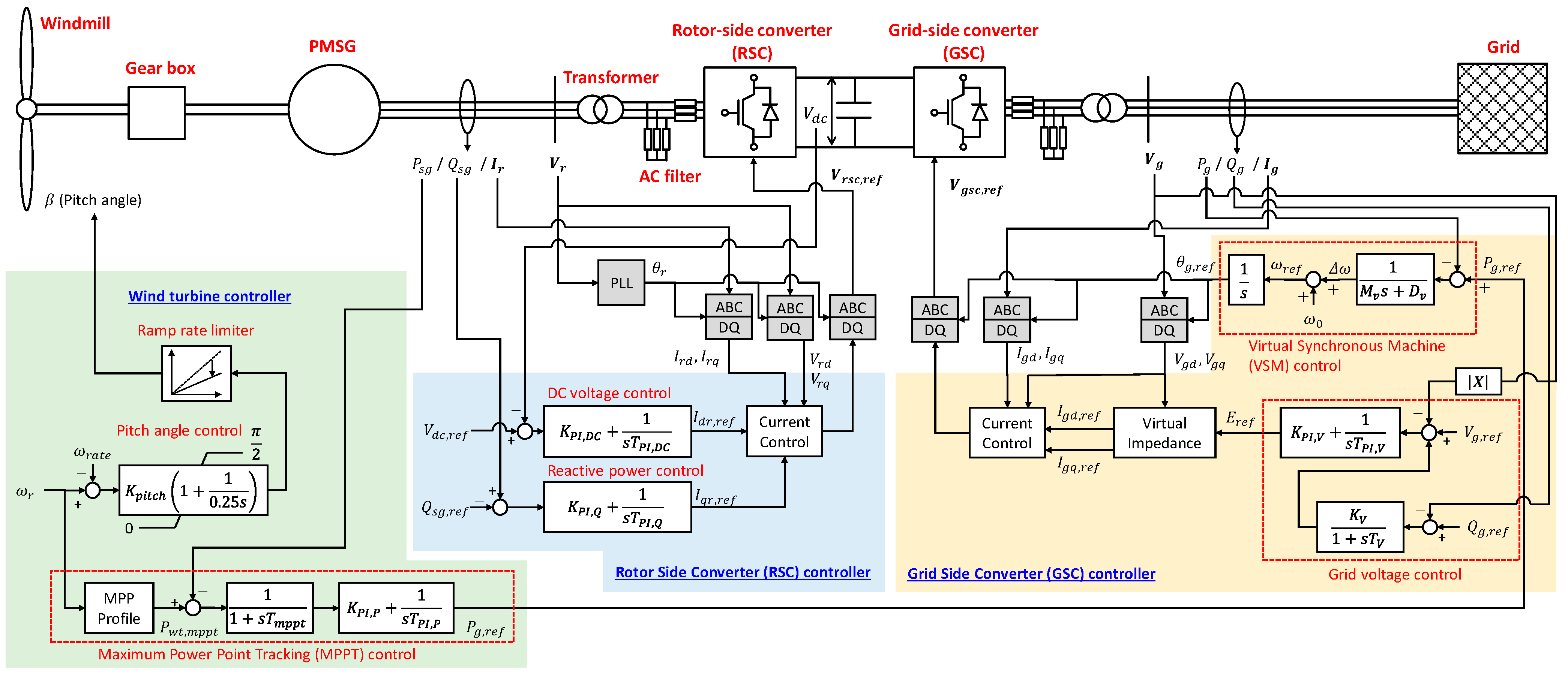
Figure 1 shows the configuration of the WTG model used in the simulation, which is developed proprietary with [27,28] for the WTG model, MPPT, and pitch angle control. The wind turbine is connected to a permanent magnet synchronous generator (PMSG), and full-rated back-to-back converters are used to establish the grid connection. This is called a Type-IV or Type-D connection [27,28]. The converter on the WT side is designated as the rotor-side converter (RSC), and that on the other side is designated as the grid-side converter (GSC). The VSM is embedded in the GSC, and the RSC contributes to the DC-voltage regulation.
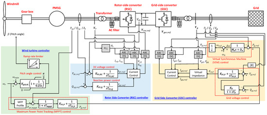
Figure 1.
Model of Type-IV wind turbine generator (WTG), and block diagram of its control system.
2.1. Wind Turbine
The output power of the wind turbine, , is expressed as follows:
where denotes the air density, denotes the wind turbine radius, denotes the power coefficient, and denotes the wind speed. is defined as the ratio of the wind turbine output to the power of the wind, and it depends on the pitch angle, , and tip-speed ratio, . is expressed as follows [27]:
where denotes the angular frequency of the wind turbine. Figure 2 depicts the operational point of the 2.5 MW-rated WTG, whose specifications are listed in Table 1. The WTG comprises four different regions of operation, as described in Section 1. In Region 2, the output increases with the increase in the wind speed since the wind energy also increases. In Region 3, the output is constant at the rated output of the WTG regardless of the wind speed.
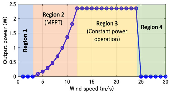
Figure 2.
WTG operating region.

Table 1.
Wind generation model specifications.
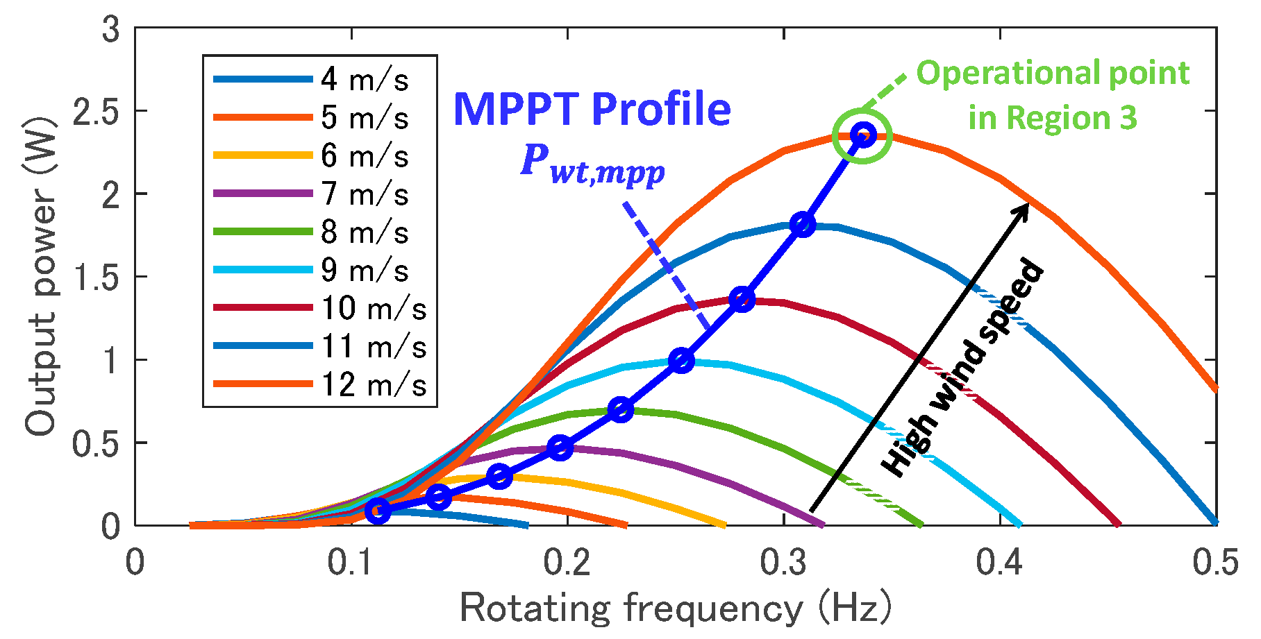
Figure 3 presents the power curves of the WTG based on the wind speed and MPPT profile, which is a trajectory of the maximum power point (MPP) at each wind speed. Here, the pitch angle, , is zero to extract the maximum energy from the wind. The power curves are described based on (1), (2), and (3). The MPPT-profile curve can be derived by solving . The tip speed ratio and power coefficient at the MPP, and , are constant, regardless of the wind speed, and are given as follows:
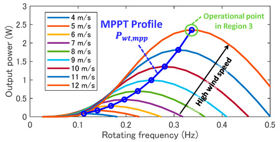
Figure 3.
Power curve of 2.5 MW WTG.
The MPPT-profile is determined from Equations (1), (3)–(5) by eliminating the wind speed, , as follows:
In Region 2, the operation point of the wind turbine is set at the MPP based on the variation of the wind speed. The pitch angle is maintained at zero, as explained above. In Region 3, the operational point of the WTG is maintained at the rated output and angular frequency by adjusting the pitch angle.
2.2. Wind Turbine Controller
The left part of Figure 1 depicts the wind turbine controller, which comprises an MPPT function and a pitch angle controller. There are various types of MPPTs [29]; in this study, we adopted the power feedback method, in which the reference of the WT output, , is updated based on Equation (6) by measuring the angular frequency, .
The output reference of the GSC, , is determined via a PI controller such that the output of the PMSG, , converges to the reference from the MPPT function, . The first lag component with the time constant, , was intentionally added in series with the PI controller to adjust the response of the MPPT. If the MPPT has fast responsivity, the operational point of the WTG is strongly held to the MPP, and the inertial response of the VSM is suppressed. The lag component is used to ensure the appropriate VSM performance.
The pitch angle control is activated when the angular frequency of the WT exceeds the rated value, and it changes the pitch angle of the blades of the wind turbine from 0° to 90° to ensure that the angular frequency converges to the rated value. The controller also contains a ramp limiter to prevent a rapid change in the pitch angle.
2.3. Rotor Side Converter (RSC) Control
The center part of Figure 1 depicts the RSC controller, which comprises the DC-link voltage and reactive power control blocks in the outer loop and current control in the inner loop. The d-axis current reference, , is computed by the PI-based DC-link voltage controller. The q-axis current reference, , is computed by a reactive power controller. The current controller presents basic functionalities [30], and the d and q-axis currents are controlled to the reference value without interference.
2.4. Grid Side Converter (GSC) Control
The right side of Figure 1 depicts the GSC controller, which comprises a VSM and grid voltage controller in the outer loop and a current controller in the inner loop. The virtual impedance block is the interface between the inner and outer loops. The VSM is designed based on the equation of motion of the synchronous generator, also known as the swing equation, which is expressed as follows:
where , , and denote the inertia constant, damping constant, and deviation of the angular frequency from the nominal value of the virtually simulated synchronous generator in the control system, respectively. The reference to the rotor angle, , represents the output of the VSM and corresponds to the phase angle of the internal induced voltage. The magnitude of the internal voltage, , is determined by the grid voltage control, in which the voltage at the point of interconnection (POI), , is maintained at the reference value, which is modified via the droop controller. The voltage reference is converted to the current reference, , in the virtual impedance block, as shown below:
Here, the bold face indicates the phasor expression. and denote the resistance and reactance components of the virtual impedance, respectively. In the VSM algorithm, the voltage source with the emulated internal voltage, , is assumed to be connected to the POI with voltage, , via the virtual impedance, .
The active power reference signal of the GSC, , is input to the VSM as the virtual mechanical input. Subsequently, the output of the GSC, , follows in the steady state, whereas the virtual inertial response is added in the transient state after the fault occurrence. In the GSC controller, the virtual rotor angle reference, , is used as a reference for Park’s transformation. A phase-locked loop (PLL) is not used in this case since is computed in the VSM block. This is one of the main requirements for grid-forming inverters.
3. Influence of Wind Turbine Control on the VSM Performance
When the VSM mounted in the GSC responds to a disturbance, such as when a generator trips, the change in the active power of the GSC reduces the DC voltage and the rotating frequency of the WT since the change in the GSC output is provided by the electrostatic energy stored in the capacitance of the DC circuit and the kinetic energy of the WT. The decrease in the rotating frequency leads to a decrease in the output of the wind turbine corresponding to the power curve, and the rotating frequency is further decreased. This negative cycle can completely halt the operation of the WTG.
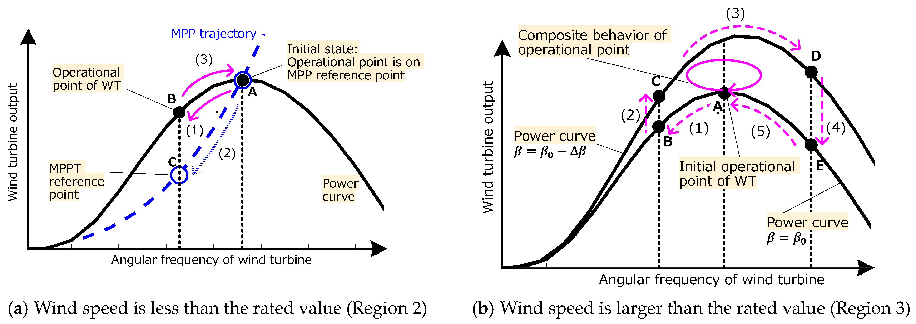
However, the MPPT and the pitch angle control can recover the operational point to one before the disturbance occurs. Figure 4a depicts an instance of the recovery process in Region 2. When the VSM increases the WTG output in the event of a generator trip, the rotating frequency of the WT, , decreases with the decrease in the mechanical output, (A->B). Simultaneously, the MPPT decreases the output reference, , along with the MPPT profile (A->C), and the PMSG output, , follows over time, corresponding to the time constant of the MPPT. Since the input of the PMSG becomes larger than the output, the PMSG starts accelerating to the initial operational point (B->A) based on the dynamics of the PMSG:
where denotes the inertia constant of the WT, denotes the gear ratio at the gear box, and denotes the number of pole pairs of PMSG. The large time constant of the MPPT causes a loss of operation of the WTG.
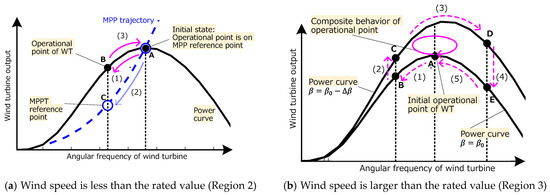
Figure 4.
Process of the operational point returning to the initial point after a disturbance due to a generator trip.
Figure 4b depicts the recovery process in Region 3. Assuming the same event described in Region 2, and are first decreased (A→B). The pitch angle control responds to the change and decreases the pitch angle, , based on the logic shown in Figure 1, leading to the increase in (B→C). The WT accelerates (C→D), and when exceeds the rated value, , the pitch angle control increases to decrease (D→E) and decelerate WT (E→A). Since the pitch angle changes in conjunction with the rotating frequency of the WT, the locus of the operational point is expected to be close to a solid line, as shown in Figure 4b. The operational point returns to the initial point while describing the spiral if the pitch angle control responds quickly to the change in the rotating frequency of the WT.
The recovery process in Region 3 has not been discussed in previous research. This paper logically indicates how the pitch angle control contributes to the process based on the characteristics of the WTG, MPPT, and the pitch angle control. The following simulation study is performed to confirm that the operational point can be restored as explained above and to explain its dependencies on the MPPT, pitch angle control, and wind speed.
4. Simulation Study
4.1. Power System Model
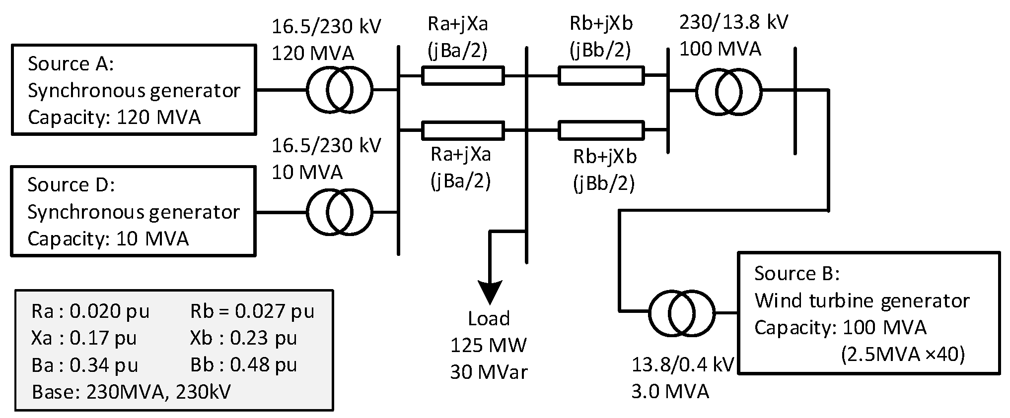
Figure 5 illustrates the three-machine system model, which was developed for this simulation. Source A represents a large-scale synchronous generator, Source D represents a small-scale generator that emulates the generator-trip event in the simulation, and Source B represents the WTG. The simulation is used to analyze the frequency regulating capability and the operation stability of the WTG with the embedded VSM (WTG-VSM) in the system where the WTG-VSM and synchronous generator coexist. The model was developed by using the least number of components possible to avoid the intervention of non-target elements [18,21,22,23]. The synchronous generator is based on Park’s model of the sixth order, and the control system comprises a speed governor and automatic voltage regulator (AVR) with a power system stabilizer (PSS) [31,32]. The total capacity of the system is 230 MVA, and the active power load is 125 MW. The rated capacity of the WTG is 100 MW, which is an integrated model of 40 WTGs connected in parallel, where each WTG has a rating of 2.5 MW. A Source D trip is a disturbance in this simulation, and the output of Source D is 5 MW, which is 4.0% of the load. The parameters of the synchronous generators, WTGs, and their controllers are listed in Appendix A.
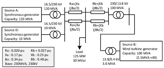
Figure 5.
Power system model.
4.2. Simulation Conditions
Using the simulation, the contribution of the WTG-VSM to the frequency stability was evaluated, and the influence of the WTG output control, such as the MPPT and pitch angle control, on the performance of the VSM in the event of a generator trip was determined. Source D is tripped at a certain instant. The frequency variation immediately after the disturbance is the analysis target. The wind speed is assumed to be constant to clearly determine the interference among the controllers. However, the wind speed affects the operation point of the WTG and stored rotating energy in the wind turbine that is available for inertia emulation by the VSM. Therefore, the simulations are performed under various wind speed conditions, as shown in Table 2. The time constant of the MPPT, , and the control gain of pitch angle control, , are also changed in a wide range to clarify the change in the interference based on these control parameters and to indicate the limit at which the WTG can be restored to stable operation without any loss of operation.
Table 2.
Parameters examined in the simulation.
The MPPT essentially deteriorates the performance of the VSM since it recovers the output of the WT to the MPP after the VSM changes the WTG output. The VSM performance can be improved by increasing the time constant of the MPPT, which was already demonstrated in [19]. In this simulation, a wide range of the time constant was analyzed, and its influence on the operation stability of the WTG was evaluated. To the best of our knowledge, this has not been reported in previous studies.
5. Simulation Results
5.1. Influence of Wind Speed on VSM Performance
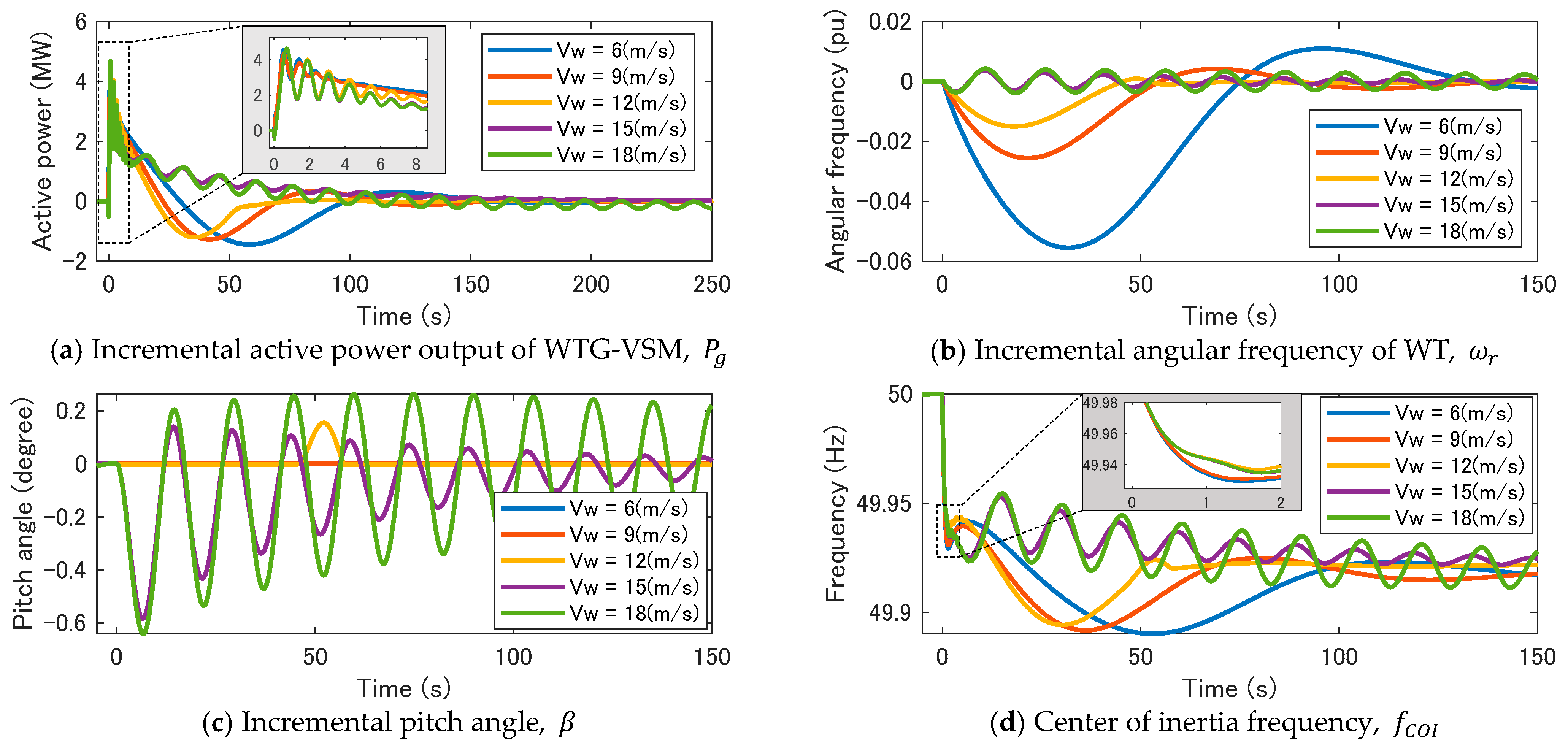
Figure 6 shows the simulation results using PSCAD/EMTDC, in which the wind speed is changed from 6 to 18 m/s, the MPPT time constant is 10 s, and the pitch angle control gain is 10. Figure 6a depicts the incremental active power of WTG-VSM, . After Source D trips at 0 s, quickly increases to cover the loss of generation like an inertial response of a synchronous generator, and there are no large differences in the inertial response produced by the wind speed. Subsequently, eventually returns to the initial value regardless of the wind speed because of the MPPT and pitch angle control, as explained in Section 3. The difference in the process of restoring the output to the initial value is caused by the difference in the properties of the operational regions. In Region 2, decreases beyond the initial value after the inertial response at approximately 50 s. This is because the MPPT decreases the power reference, , in response to the change in the rotating frequency, , as shown in Figure 6b. recovers owing to the decrease in . The higher the wind speed, the smaller the frequency drop since the kinetic energy in the WT is larger at a higher wind speed. Conversely, in Region 3, gradually approaches the initial value without a large temporal drop. The pitch angle control quickly responds to the decrease in , as shown in Figure 6c, and output of the WT increases, which primarily helps to restore the operational state. rarely decreases owing to the MPPT in Region 3 since the response of the pitch angle control is remarkably quick.
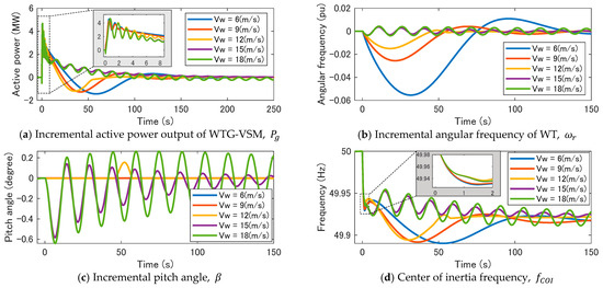
Figure 6.
Response of WTG-VSM based on wind speed. MPPT time constant Tmppt = 10, pitch angle control gain Kpitch = 10.
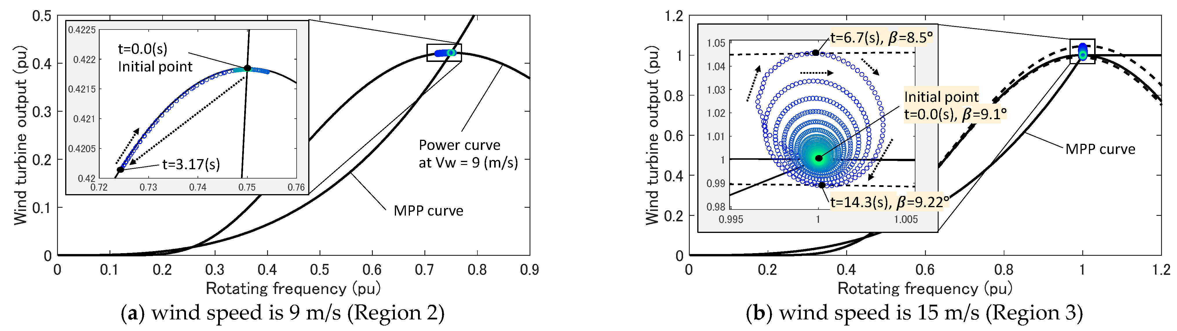
Figure 7 reveals the trajectory of the operational point of the WTG. At a low wind speed of 9 m/s, as shown in Figure 7a, the operational point drops along the power curve and subsequently returns to the initial point, as explained in Section 3, Figure 4a. At a high wind speed of 15 m/s, as shown in Figure 7b, the operational point converges to the initial point while describing a spiral, as explained in Section 3, Figure 4b. Thus, the behavior of the operational point in the recovery process is confirmed to be consistent with the assumption made in Section 3.
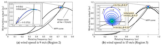
Figure 7.
Trajectory of the operational point of the WTG, which is plotted based on the simulation results.
Figure 6d presents the system frequency, where the center of inertia (COI) of the frequency is plotted. The COI frequency, , is expressed as follows:
where denotes the total number of generators, denotes the index number of each generator, denotes the rated capacity, and denotes the inertial constant. represents the average frequency among the synchronous generators, where the inter-generator oscillation between them is omitted. It is often employed in the discussion of the frequency stability of the entire power system [32,33]. In this study, the WTG-VSM was included as a generation unit considered in the computation of . To quantitatively evaluate the frequency stability, three indices, frequency nadir, , first local frequency nadir, , and the rate of change in frequency (RoCoF), are introduced. is the minimum value of frequency that appears after a disturbance, and it is expressed as follows:
indicates the local minimum value of the COI frequency that appears immediately after the disturbance. This index is primarily used to determine the effectiveness of the inertial response emulated by the VSM. For the transient state where the inertial response is involved, will have no value if the local minimum value does not appear within 5 s of the disturbance occurrence. This period is a representative duration of fast frequency response (FFR) [34,35]. For RoCoF, the maximum rate of change appearing in the transient state is evaluated as follows:
The frequency slope was computed every 100 ms until 5 s after the disturbance, and the maximum slope was selected as the RoCoF.
Table 3 lists the evaluation indices computed from the simulation results. All the indices are better in Region 3 than in Region 2. In Region 2, the MPPT decreases the output of the WTG, , after the VSM increases . Since the supply power decreases and the supply–demand balance becomes worse, the frequency, , drops drastically, leading to worse evaluation indices. The results in the simulations under other parameter sets are depicted in Figure A1 in Appendix B, and the same tendency can be observed for the wind speed change.
Table 3.
Performance Indices by Wind Speed (Kpitch = 10, Tmppt = 10).
5.2. Influence of Time Constant of MPPT Function
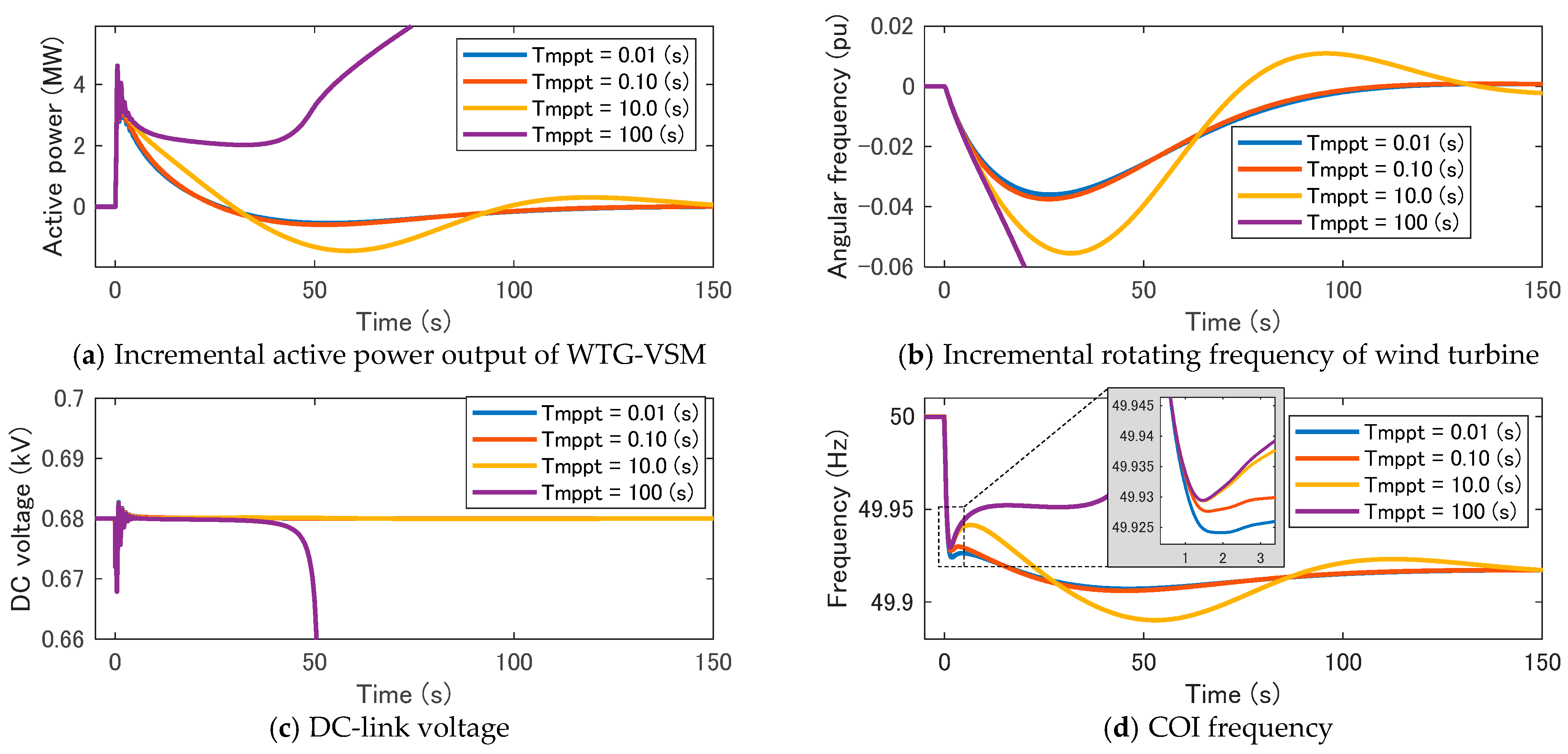
In Region 2, the MPPT helps in recovering the operational state after the VSM responds to the disturbance. The time constant of the MPPT, , is an important element that determines the operational stability of the WTG and the performance of the VSM. Figure 8 presents the results of the simulation. As shown in the figure, varies from 0.01 s to 100 s, the wind speed is 6 m/s, and the pitch angle control gain is 10.
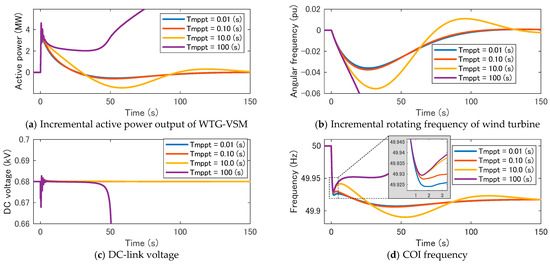
Figure 8.
Influence of time constant of MPPT (VW = 6 m/s).
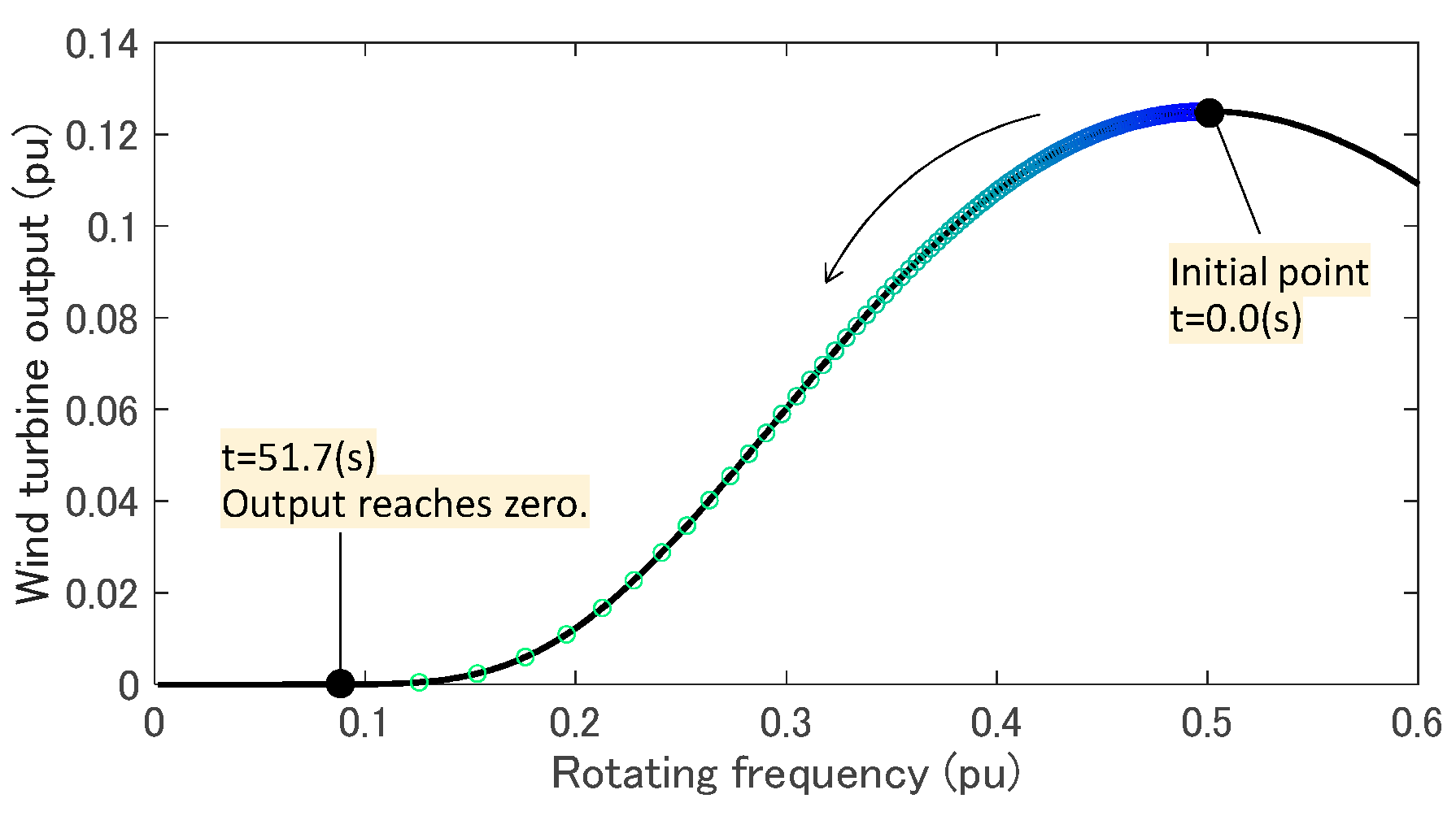
The active power output of the WTG-VSM, , quickly increases in response to the generation trip by a function of the VSM, and it converges to the initial value by the MPPT function, as shown in Figure 8a. The larger the value, the slower the convergence. When is 100 s, diverges since the large delay in the MPPT leads to a decrease in the rotating frequency of WT, , and DC-link voltage, , as shown in Figure 8b,c, respectively, and eventually, the WTG cannot continue its operation. Figure 9 depicts the trajectory of the operational point of WT. When is 100 s, the operational point falls to the bottom of the power curve.
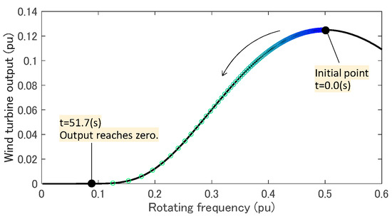
Figure 9.
Trajectory of the operational point of WT. MPPT time constant is 100 s, and wind speed VW is 6 m/s.
Figure 8d depicts the COI frequency, , and Table 4 lists the evaluation indices. The larger leads the larger first local frequency nadir, , and RoCoF but not the lower frequency nadir, . Since the MPPT with a large does not suppress the inertial response produced by the VSM within a short period, and RoCoF are improved as becomes large. However, a large causes a large drop in tens of seconds after the disturbance, which deteriorates . Thus, the lag component with time constant, , presents a risk of loss of operation of the WTG even though the performance of the VSM in the transient state can be improved. The results of the simulation in the other parameter sets are shown in Figure A2 in Appendix B, and the same tendency can be observed for the change in .
Table 4.
Performance Indices by MPPT Time Constant (Kpitch = 10, VW = 6).
5.3. Influence of Pitch Angle Control Gain on VSM Performance
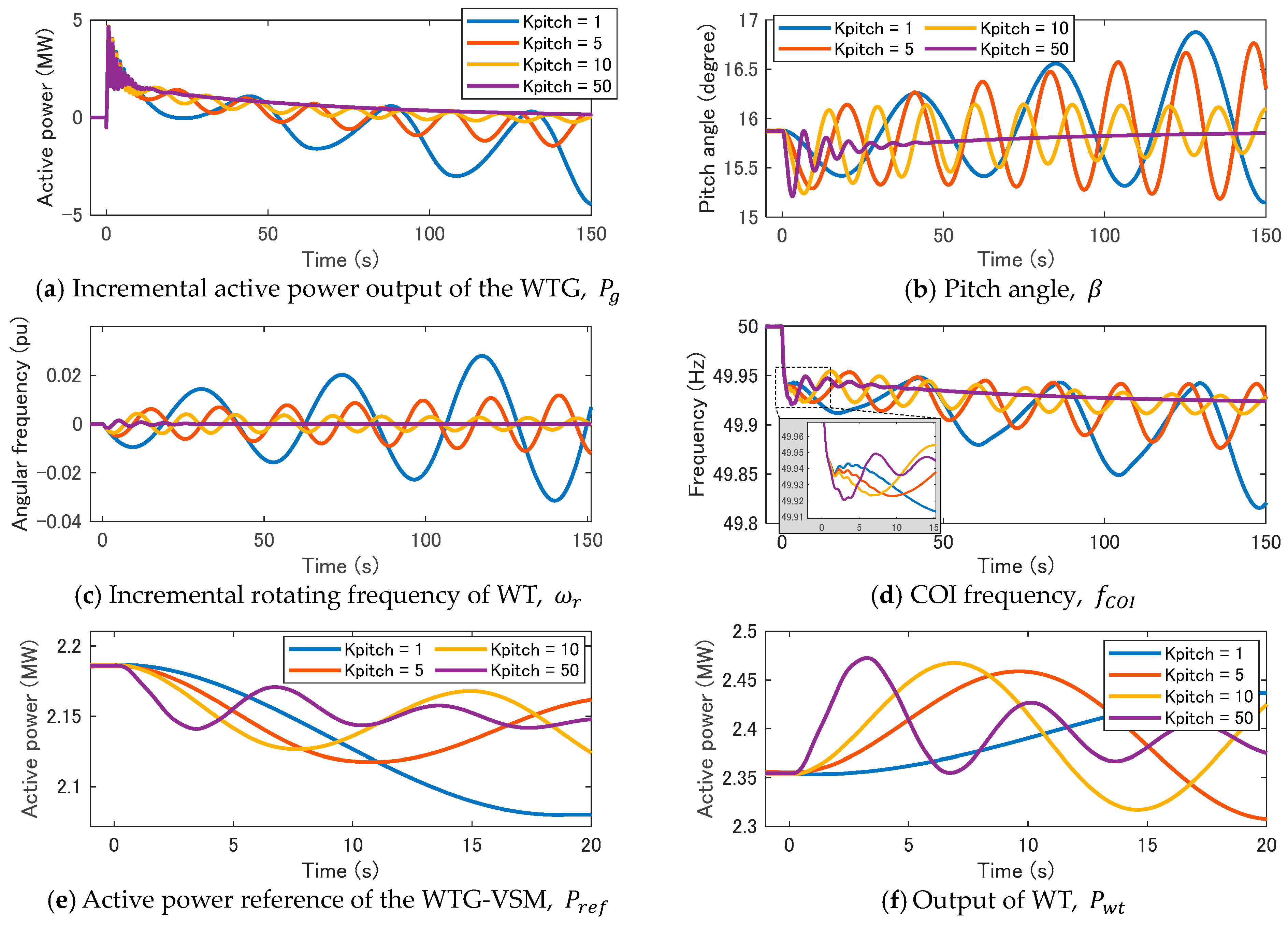
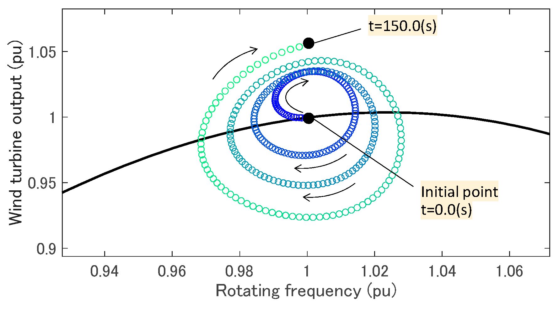
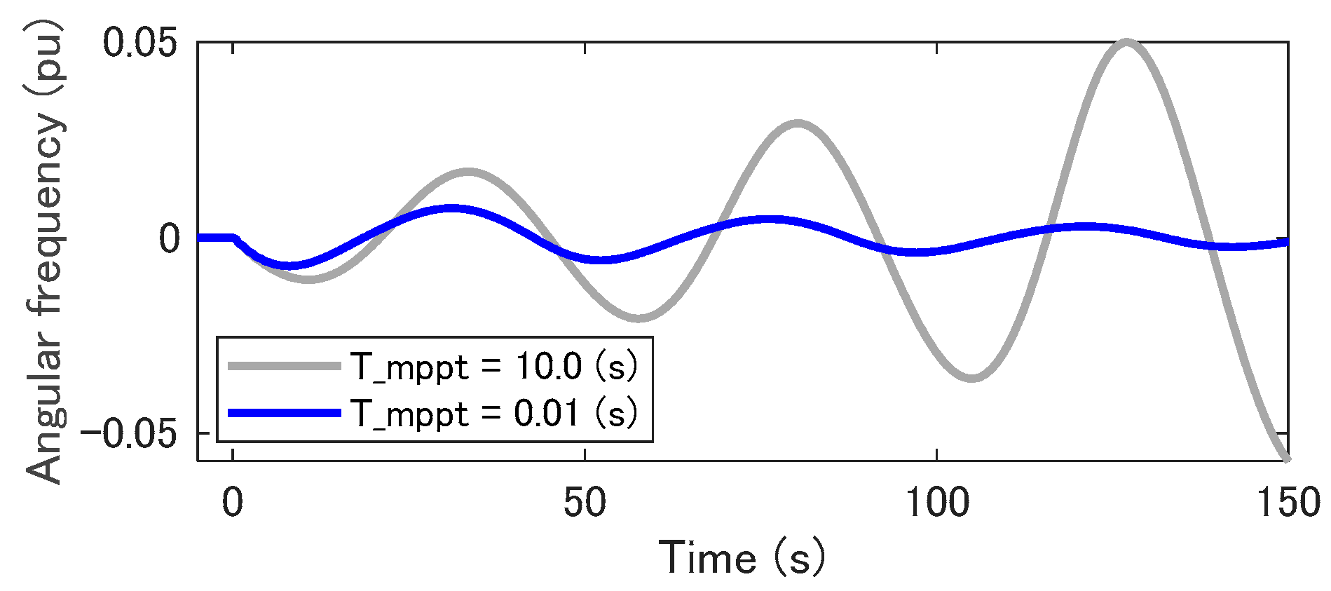
In Region 3, the pitch angle control primarily adjusts the output of the WTG for the variation in wind speed. The pitch angle control is expected to help in recovering the operational state after the VSM responds to the disturbance. Figure 10 presents the results of the simulations in which the pitch angle control gain, , changes from 1 to 50, the MPPT time constant, , is 10 s, and wind speed is 18 m/s. When is larger than 10, the active power of WTG-VSM, , converges to the initial value after inertial response by VSM, while diverges at less , as shown in Figure 10a. The small value of leads to a slow response of the pitch angle control, as shown in Figure 10b, and the oscillation in the rotating frequency of the WT, , cannot be damped, as shown in Figure 10c. Figure 11 shows the trajectory of the operational point of the WT when is 1. Although and the WT output, , oscillate around the initial value in a spiral, the operation point gradually moves far away from the initial point. This instability can be covered by the MPPT. Figure 12 depicts the time variance of when the MPPT time is constant, , is changed from 10 s to 0.01 s. The MPPT helps in Increasing while is less than the rated value, covering the slow response of the pitch angle control. However, the short time constant in the MPPT deteriorates the VSM performance from the perspective of frequency regulation, as discussed above.
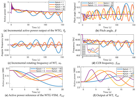
Figure 10.
Influence of pitch angle control gain. The delay of MPPT is 10 (s), wind speed is 18 (m/s).
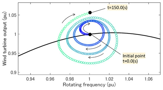
Figure 11.
Trajectory of the operational point of WT. MPPT time constant Tmppt is 10 s, the pitch angle control gain Kpitch is 1, and wind speed VW is 18 m/s.
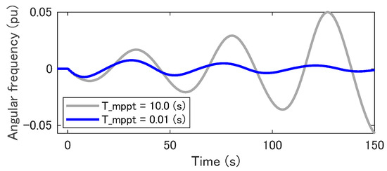
Figure 12.
Stabilization of the WTG operation by giving short time constant of MPPT in Region 3. The pitch angle control gain Kpitch is 1, and wind speed VW is 18 m/s.
Figure 10d depicts the COI frequency, , and Table 5 lists the evaluation indices. At a high , is high, but is low. The high gain of the pitch angle control brings fast convergence of oscillation in the operational state, leading to high . Conversely, in the transient state within 5 s from the disturbance occurrence, the VSM decreases the output frequency according to (4) for the large decrease in the reference power, , as shown in Figure 10e. The quick response of the pitch angle control increases for the decrease in , as shown in Figure 10f. Since becomes significantly larger than the MPPT reference, , the MPPT decreases so that follows . Thus, needs to be high for the stable operation of the WTG-VSM and to ensure long-term frequency stability, but the performance of the VSM in a transient state deteriorates as increases. Figure A3 of Appendix B presents the results of the simulations, where the same tendency is observed when the other parameter sets are applied.
Table 5.
Performance indices by pitch angle control gain (Tmppt = 10 (s), VW = 18 (m/s)).
6. Conclusions
This study analyzed the performance of a wind turbine generator with a virtual synchronous machine (WTG-VSM). We primarily focused on the influence of the wind speed and control parameters of the MPPT and pitch angle control in the event of a frequency drop caused by a tripped generator. The WTG-VSM can provide an inertial response like a synchronous generator by using the rotating energy in the WT, but the consumed energy must be restored to avoid a loss of operation of WTG. The MPPT and pitch angle control were originally provided with a function that holds a specified operational state in the constant wind speed condition. They are expected to help in recovering the operational state after the VSM responds to the disturbance.
The theoretical consideration based on the characteristics of the WTG and simulation demonstrates that the MPPT and pitch angle control basically contribute to recovering the energy released from the WT for the inertial response emulation by the VSM. Furthermore, it is observed that the VSM performance during short-term frequency regulation immediately after a disturbance can be improved by slowing down the responsivity of the MPPT and the pitch angle control. Conversely, the slow response of those controllers deteriorates the long-term frequency regulation capability of the VSM since the energy released from the WT increases as the response slows down. Additionally, the simulation demonstrates that the recovery process fails and the operation of the WTG stops if the responsivity is set considerably slow.
Those findings indicate that the parameters of VSM, MPPT, and pitch angle control need to be tuned considering the interaction among them to maintain the stable operation of the WTG and maximize the VSM performance. The results of the research are expected to be a guideline for that. On the other hand, determining the optimal parameterization and criteria for the stability of the operation was a considerable challenge. The verification of the simulation results through an experimental study is also important for future work.
Author Contributions
Conceptualization, D.O.; methodology, D.O.; software, D.O.; validation, D.O. and H.T.; formal analysis, D.O.; investigation, D.O. and H.T.; resources, D.O.; data curation, D.O.; writing—original draft preparation, D.O.; writing—review and editing, D.O., H.T. and K.O.; visualization, D.O., and H.T.; supervision, K.O.; All authors have read and agreed to the published version of the manuscript.
Funding
This research received no external funding.
Data Availability Statement
Data is contained within the article.
Conflicts of Interest
The authors declare no conflict of interest.
Appendix A
Details of the model for the simulation study
Table A1.
Parameters of the Synchronous Generator Model.
Table A1.
Parameters of the Synchronous Generator Model.
| Parameter | Source A | Source D | PMSG (WTG) |
|---|---|---|---|
| Rated capacity (MVA) | 120 | 10.0 | 100 |
| Rated voltage (kV) | 16.5 | 16.5 | 0.40 |
| Rated frequency (Hz) | 50.0 | 50.0 | 55.5 |
| Inertia constant (s) | 4.0 | 4.0 | 4.0 |
| d-axis unsaturated reactance | 1.7 | 1.7 | 0.36 |
| q-axis unsaturated reactance | 1.6 | 1.6 | 0.25 |
| d-axis unsaturated transient reactance | 0.23 | 0.23 | 0.15 |
| d-axis unsaturated sub-transient reactance | 0.23 | 0.23 | 0.15 |
| q-axis unsaturated sub-transient reactance | 0.23 | 0.23 | 0.15 |
| d-axis unsaturated transient time | 5.9 | 5.9 | 9.0 |
| d-axis unsaturated sub-transient time | 0.010 | 0.010 | 0.010 |
| q-axis unsaturated sub-transient time | 0.010 | 0.010 | 0.010 |
| Armature time constant | 0.40 | 0.40 | 0.33 |
| Potier reactance | 0.095 | 0.095 | 0.080 |
Table A2.
Parameters of the WTG controller.
Table A2.
Parameters of the WTG controller.
| Parameter | Symbol | Value |
|---|---|---|
| MPPT PI control proportional gain | 0.30 | |
| MPPT PI control integral time (s) | 30.0 | |
| DC voltage control (RSC) proportional gain | 5.0 | |
| DC voltage control (RSC) integral time (s) | 0.20 | |
| Reactive power control (RSC) proportional gain | 0.20 | |
| Reactive power control (RSC) integral time (s) | 0.10 | |
| Grid voltage control (GSC) proportional gain | 0.01 | |
| Grid voltage control (GSC) integral time (s) | 1.0 | |
| Voltage droop control (GSC) gain | 0.20 | |
| Voltage droop control (GSC) time constant (s) | 0.020 | |
| VSM (GSC) inertia constant (s) | 8.0 | |
| VSM (GSC) damping coefficient | 25.0 | |
| VSM (GSC) virtual resistance (pu) | 0.20 | |
| VSM (GSC) virtual reactance (pu) | 0.30 |
Appendix B
Details of the results of the simulation study
Table A3 reveals the operation stability of the WTG-VSM in the event of a generator trip. When the WTG cannot continue operation because of the failure of the recovery of the operation after the inertial response emulation, it is described as ‘Unstable’ in the table.
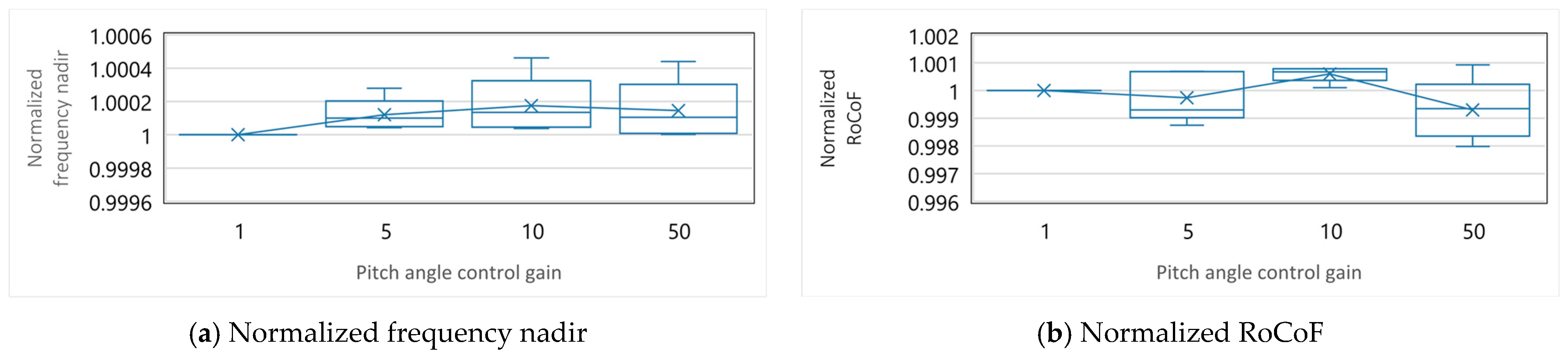
Figure A1 shows the dependency of the evaluation indices for frequency stability on the wind speed. The evaluation indices of the simulations with the same combination of the MPPT time constant and pitch angle control gain are normalized by the value in the case where the wind speed is 6 m/s. The normalized indices of the simulations with all the parameter sets are shown as a box-and-beard diagram by the wind speed. Figure A2 depicts the dependency of the evaluation indices on the MPPT time constant. The normalization of the evaluation indices is performed in a similar manner. Lastly, Figure A3 depicts the dependency of the evaluation indices on the pitch angle control gain. The normalization of the evaluation indices is performed in a similar manner.
Table A3.
Stability of the Operation of the Wind Turbine Generator.
Table A3.
Stability of the Operation of the Wind Turbine Generator.
| Wind Speed (m/s) | Pitch Angle Control Gain | MPPT Time Constant (s) | |||
|---|---|---|---|---|---|
| 0.01 | 1 | 10 | 100 | ||
| 6 | 1 | Stable | Stable | Stable | Unstable |
| 5 | Stable | Stable | Stable | Unstable | |
| 10 | Stable | Stable | Stable | Unstable | |
| 50 | Stable | Stable | Stable | Unstable | |
| 9 | 1 | Stable | Stable | Stable | Unstable |
| 5 | Stable | Stable | Stable | Unstable | |
| 10 | Stable | Stable | Stable | Unstable | |
| 50 | Stable | Stable | Stable | Unstable | |
| 12 | 1 | Stable | Stable | Stable | Stable |
| 5 | Stable | Stable | Stable | Stable | |
| 10 | Stable | Stable | Stable | Stable | |
| 50 | Stable | Stable | Stable | Stable | |
| 15 | 1 | Stable | Stable | Stable | Unstable |
| 5 | Stable | Stable | Stable | Stable | |
| 10 | Stable | Stable | Stable | Stable | |
| 50 | Stable | Stable | Stable | Stable | |
| 18 | 1 | Stable | Stable | Unstable | Unstable |
| 5 | Stable | Stable | Unstable | Unstable | |
| 10 | Stable | Stable | Stable | Stable | |
| 50 | Stable | Stable | Stable | Stable | |
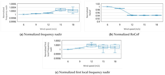
Figure A1.
Box-and-beard diagram of normalized evaluation indices by wind speed.
Figure A1.
Box-and-beard diagram of normalized evaluation indices by wind speed.
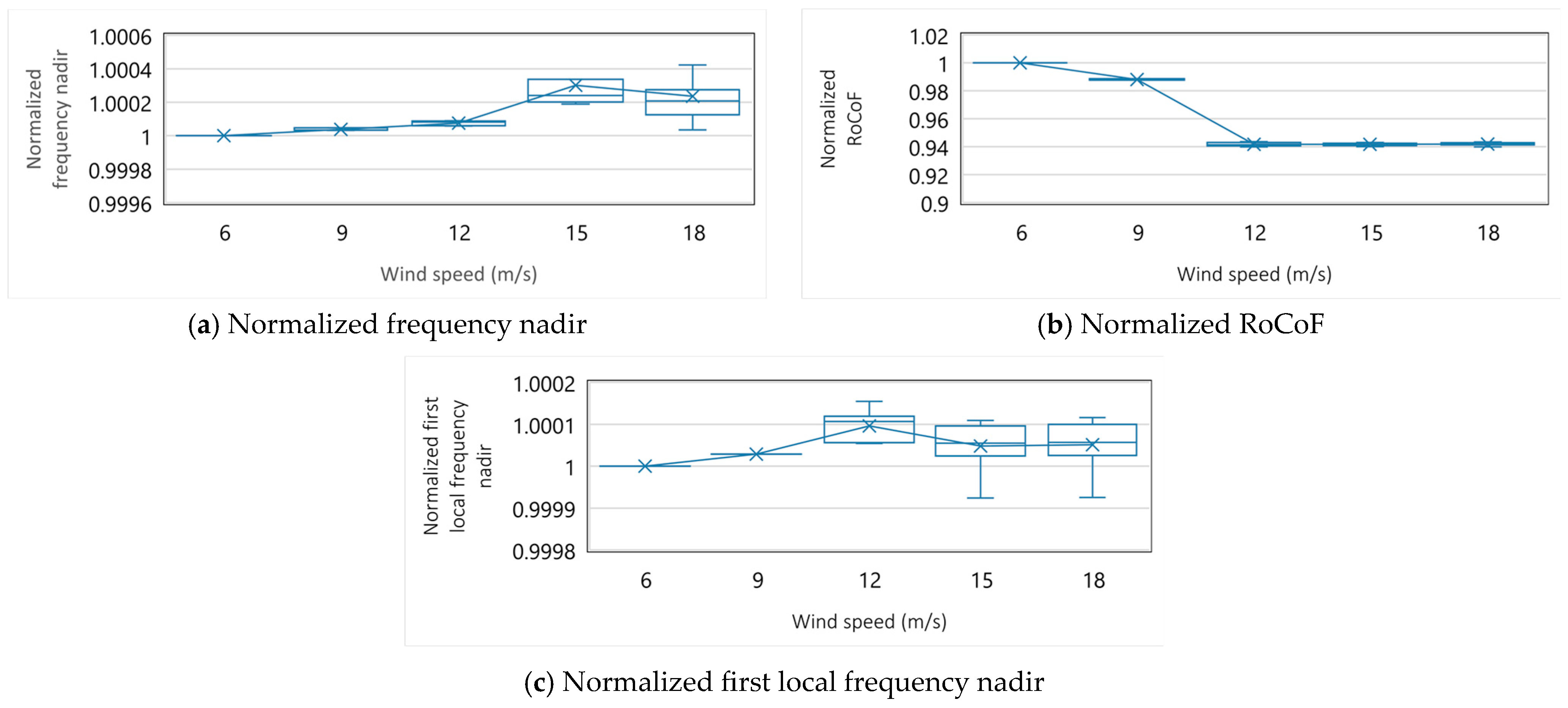
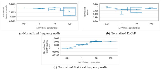
Figure A2.
Box-and-beard diagram of normalized evaluation indices by MPPT time constant.
Figure A2.
Box-and-beard diagram of normalized evaluation indices by MPPT time constant.


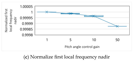
Figure A3.
Box-and-beard diagram of normalized evaluation indices by pitch angle control gain.
Figure A3.
Box-and-beard diagram of normalized evaluation indices by pitch angle control gain.

References
- Beck, H.-P.; Hesse, R. Virtual Synchronous Machine. In Proceedings of the 9th International Conference on Electrical Power Quality and Utilisation, Barcelona, Spain, 9–11 October 2007. [Google Scholar] [CrossRef]
- Ekanayake, J.B.; Jenkins, N.; Strbac, G. Frequency Response from Wind Turbines. Wind Eng. 2008, 32, 573–586. [Google Scholar] [CrossRef]
- Karbouj, H.; Rather, Z.H.; Flynn, D.; Qazi, H.W. Non-synchronous Fast Frequency Reserves in Renewable Energy Integrated Power Systems: A Critical Review. Int. J. Electr. Power Energy Syst. 2019, 106, 488–501. [Google Scholar] [CrossRef]
- Janssens, N.A.; Lambin, G.; Bragard, N. Active Power Control Strategies of DFIG Wind Turbines. In Proceedings of the 2007 IEEE Lausanne Power Tech, Lausanne, Switzerland, 1–5 July 2007; IEEE Publications Lausanne Power Tech: Lausanne, Switzerland, 2007. [Google Scholar] [CrossRef]
- Moutis, P.; Loukarakis, E.; Papathanasiou, S.; Hatziargyriou, N.D. Primary Load-Frequency Control from Pitch-Controlled Wind Turbines. In Proceedings of the 2009 IEEE Bucharest PowerTech, Bucharest, Romania, 28 June–2 July 2009. [Google Scholar] [CrossRef]
- Nguyen, X.H.; Nakajima, T.; Ota, Y. Droop-Based Grid-Forming Function by Type IV Wind Farm for Fast Frequency Control. In Proceedings of the 2021 IEEE PES Innovative Smart Grid Technologies-Asia (ISGT Asia), Brisbane, Australia, 5–8 December 2021. [Google Scholar] [CrossRef]
- Moutis, P.; Papathanassiou, S.A.; Hatziargyriou, N.D. Improved Load-Frequency Control Contribution of Variable Speed Variable Pitch Wind Generators. Renew. Energy 2012, 48, 514–523. [Google Scholar] [CrossRef]
- Lyu, X.; Subotić, I.; Groß, D. Unified Grid-Forming Control of PMSG Wind Turbines for Fast Frequency Response and MPPT. In Proceedings of the IREP Bulk Power System Dynamics and Control Symposium, Banff, AB, Canada, 25–30 July 2022. [Google Scholar] [CrossRef]
- Wind Energy Generation Systems–Part 21–1: Measurement and Assessment of Electrical Characteristics–Wind Turbines, IEC 61400-21-1. Available online: https://webstore.iec.ch/publication/29528. (accessed on 29 December 2023).
- Ullah, N.R.; Thiringer, T.; Karlsson, D. Temporary Primary Frequency Control Support by Variable Speed Wind Turbines—Potential and Applications. IEEE Trans. Power Syst. 2008, 23, 601–612. [Google Scholar] [CrossRef]
- El Itani, S.; Annakkage, U.D.; Joos, G. Short-Term Frequency Support Utilizing Inertial Response of DFIG Wind Turbines. In Proceedings of the 2011 IEEE Power and Energy Society General Meeting, Detroit, MI, USA, 24–28 July 2011; pp. 1–8. [Google Scholar] [CrossRef]
- Kang, M.; Muljadi, E.; Hur, K.; Kang, Y.C. Stable Adaptive Inertial Control of a Doubly Fed Induction Generator. IEEE Trans. Smart Grid. 2016, 7, 2971–2979. [Google Scholar] [CrossRef]
- Aho, J.; Buckspan, A.; Laks, J.; Fleming, P.; Jeong, Y.; Dunne, F.; Churchfield, M.; Pao, L.; Johnson, K. A Tutorial of Wind Turbine Control for Supporting Grid Frequency Through Active Power Control. In Proceedings of the American Control Conference (ACC), Montreal, QC, Canada, 27–29 June 2012. [Google Scholar] [CrossRef]
- Anaya-Lara, O.; Jenkins, N.; Ekanayake, J.B.; Cartwright, P.; Hughes, M. Wind Energy Generation: Modelling and Control; John Wiley & Sons: Chichester, UK, 2009. [Google Scholar]
- Nguyen, T.; Vu, T.; Paudyal, S.; Blaabjerg, F.; Long Vu, T.L. Grid-Forming Inverter-Based Wind Turbine Generators: Comprehensive Review, Comparative Analysis, and Recommendations. arXiv 2022, arXiv:2203.02105. [Google Scholar] [CrossRef]
- Wang, Y.; Meng, J.; Zhang, X.; Xu, L. Control of PMSG-Based Wind Turbines for System Inertial Response and Power Oscillation Damping. IEEE Trans. Sustain. Energy 2015, 6, 565–574. [Google Scholar] [CrossRef]
- Kheshti, M.; Ding, L.; Nayeripour, M.; Wang, X.; Terzija, V. Active Power Support of Wind Turbines for Grid Frequency Events Using a Reliable Power Reference Scheme. Renew. Energy 2019, 139, 1241–1254. [Google Scholar] [CrossRef]
- Zhou, B.; Bian, X.; Zhang, J.; Lou, P.; Zhang, L.; Wang, X. Dynamic Frequency Regulation of Microgrid Based on Double-Layer Adaptive Virtual Inertia Control of DFIG; IEEE: Shanghai, China, 2022; pp. 1073–1081. [Google Scholar] [CrossRef]
- Kang, M.; Lee, J.; Kang, Y.C. Modified Stepwise Inertial Control Using the Mechanical Input and Electrical Output Curves of a Doubly Fed Induction Generator. In Proceedings of the 9th International Conference on Power Electronics and ECCE Asia (ICPE-ECCE Asia), Seoul, Republic of Korea, 1–5 June 2015. [Google Scholar] [CrossRef]
- Heidary Yazdi, S.S.; Milimonfared, J.; Fathi, S.H.; Rouzbehi, K.; Rakhshani, E. Analytical Modeling and Inertia Estimation of VSG-Controlled Type 4 WTGs: Power System Frequency Response Investigation. Int. J. Electr. Power Energy Syst. 2019, 107, 446–461. [Google Scholar] [CrossRef]
- Sun, C.; Ali, S.Q.; Joos, G.; Bouffard, F. Improved VSG Control for Type-IV Wind Turbine Generator Considering Operation Limitations. In Proceedings of the IEEE Energy Conversion Congress and Exposition (ECCE), Baltimore, MD, USA, 29 September–3 October 2019. [Google Scholar] [CrossRef]
- Zhu, J.; Hu, J.; Hung, W.; Wang, C.; Zhang, X.; Bu, S.; Li, Q.; Urdal, H.; Booth, C.D. Synthetic Inertia Control Strategy for Doubly Fed Induction Generator Wind Turbine Generators Using Lithium-Ion Supercapacitors. IEEE Trans. Energy Convers. 2018, 33, 773–783. [Google Scholar] [CrossRef]
- Li, Y.; Yuan, X.; Li, J.; Xiao, H.; Xu, Z.; Du, Z. Novel Grid-Forming Control of PMSG-Based Wind Turbine for Integrating Weak AC Grid Without Sacrificing Maximum Power Point Tracking. IET Gener. Transm. Distrib. 2021, 15, 1613–1625. [Google Scholar] [CrossRef]
- Li, S.; Hu, J.; Wang, S.; He, H.; Wang, L.; Liu, G. A Novel Inertial Control Strategy for Full-Capacity Wind Turbine with PLL by Optimizing Internal Potential Response. In Proceedings of the 17th International Conference on Electrical Machines and Systems (ICEMS), Hangzhou, China, 22–25 October 2014. [Google Scholar] [CrossRef]
- Jiang, Q.; Zeng, X.; Li, B.; Wang, S.; Liu, T.; Chen, Z.; Wang, T.; Zhang, M. Time-Sharing Frequency Coordinated Control Strategy for PMSG-Based Wind Turbine. IEEE J. Emerg. Sel. Top. Circuits Syst. 2022, 12, 268–278. [Google Scholar] [CrossRef]
- Li, Y.; Xu, Z.; Wong, K.P. Advanced Control Strategies of PMSG-Based Wind Turbines for System Inertia Support. IEEE Trans. Power Syst. 2017, 32, 3027–3037. [Google Scholar] [CrossRef]
- Ackermann, T. Wind Power in Power Systems, 2nd ed.; John Willey & Sons Ltd: Chichester, UK, 2012; pp. 827–828. [Google Scholar]
- Pourbeik, P.; Ellis, A.; Sanchez-Gasca, J.; Kazachkov, Y.; Muljadi, E.; Senthil, J.; Davies, D. Generic Stability Models for Type 3 & 4 Wind Turbine Generators for WECC. In Proceedings of the 2013 IEEE Power & Energy Society General Meeting, Vancouver, BC, Canada, 21–25 July 2013; pp. 1–5. [Google Scholar] [CrossRef]
- Wu, B.; Lang, Y.; Zargari, N.; Kouro, S. Power Conversion and Control of Wind Energy System; Wiley-IEEE Press: Hoboken, NJ, USA, 2011. [Google Scholar] [CrossRef]
- Rowan, T.M.; Kerkman, R.J. A New Synchronous Current Regulator and an Analysis of Current-Regulated PWM Inverters. IEEE Trans. Ind. Appl. 1986, IA-22, 678–690. [Google Scholar] [CrossRef]
- Institution of Electrical Engineering in Japan. Japanese Power System Model. Available online: http://www.iee.or.jp/pes/model/english/ (accessed on 29 December 2023).
- Orihara, D.; Kikusato, H.; Hashimoto, J.; Otani, K.; Takamatsu, T.; Oozeki, T.; Taoka, H.; Matsuura, T.; Miyazaki, S.; Hamada, H.; et al. Contribution of Voltage Support Function to Virtual Inertia Control Performance of Inverter-Based Resource in Frequency Stability. Energies 2021, 14, 4220. [Google Scholar] [CrossRef]
- Zhao, J.; Tang, Y.; Terzija, V. Robust Online Estimation of Power System Center of Inertia Frequency. IEEE Trans. Power Syst. 2019, 34, 821–825. [Google Scholar] [CrossRef]
- Entso, E. Technical Requirements for Fast Frequency Reserve Provision in the Nordic Synchronous Area-External Document. Available online: https://www.statnett.no/globalassets/for-aktorer-i-kraftsystemet/marked/reservemarkeder/ffr/technical-requirements-for-ffr-v1.1.pdf (accessed on 29 December 2023).
- FINGRID. The Technical Requirements and the Pre-Qualification Process of Fast Frequency Reserve (FFR). Available online: https://www.fingrid.fi/globalassets/dokumentit/fi/sahkomarkkinat/reservit/the-technical-requirements-and-the-prequalification-process-of-fast-frequency-reserve-ffr-as-of-22-may-2023.pdf (accessed on 29 December 2023).
Disclaimer/Publisher’s Note: The statements, opinions and data contained in all publications are solely those of the individual author(s) and contributor(s) and not of MDPI and/or the editor(s). MDPI and/or the editor(s) disclaim responsibility for any injury to people or property resulting from any ideas, methods, instructions or products referred to in the content. |
© 2024 by the authors. Licensee MDPI, Basel, Switzerland. This article is an open access article distributed under the terms and conditions of the Creative Commons Attribution (CC BY) license (https://creativecommons.org/licenses/by/4.0/).