Abstract
Hydrogen blending of pulverized coal in boilers is a promising technology. However, there are few studies on hydrogen blending in coal-fired boilers. In order to reduce CO2 emissions from coal-fired boilers, this study investigates the co-combustion of pulverized coal and hydrogen in a swirl pulverized coal burner by numerical simulation. Itis shown that the burnout rate of fuel is 5.08% higher than that of non-hydrogen blended coal when the percentage of hydrogen blended is 5%. The water vapor generated by hydrogen blending not only leads to the formation of a low-temperature zone near the burner outlet; it also results in a prolonged burnout time of moist pulverized coal and a high-temperature zone near the furnace outlet. The greater the amount of hydrogen for blending, the higher the water produced. When 1–3% hydrogen is blended, the water vapor in the furnace reacts with the carbon to produce a large amount of CO. When the amount of hydrogen added to the furnace is more than 3%, the water content in the furnace rises, resulting in a lower temperature at the burner outlet and a decrease in the amount of CO produced. When 1–3% hydrogen is blended, the CO2 emission rises. The CO2 emission decreased by 1.49% for 5% hydrogen blending compared to non-hydrogen blending and by 3.22% compared to 1% hydrogen blending.
1. Introduction
China places significant emphasis on decreasing CO2 emissions to accomplish its carbon-neutral objective. Burning fossil fuels produces a lot of CO2. In 2020, of China’s total CO2 emissions, coal-fired power plants (CFPPs) produced 51.5% of CO2 emissions [1]. Therefore, reducing CO2 emissions from CFPPs is crucial. In CFPPs, the use of low-carbon fuels or carbon-free fuels to replace or partially replace pulverized coal is an important way to reduce CO2 production. The choice of which fuel to use as a replacement for pulverized coal to reduce carbon emissions in the power plant sector has become a key issue that needs to be addressed now. There is an urgent need to develop relevant carbon-reduction technologies.
The burner is the key device in CFPPs. It influences the combustion process of fuels and the emission of pollutants. In prior research, researchers have extensively investigated the effects of parameters such as oxygen enriched combustion [2], air ratio [3], and swirl intensity [4] on burner operation. However, the objective of these studies was mainly about enhancing combustion efficiency and minimizing emissions of pollutants. There have been few studies dedicated to reduction in CO2 emissions. Mixing carbon-free fuels with pulverized coal for combustion can effectively reduce carbon emissions. Ammonia is an excellent carbon-free fuel, and complete combustion of ammonia under ideal conditions only generates N2 and water [5,6,7,8]. Therefore, combusting ammonia and pulverized coal mixtures can demonstrate ammonia’s low-carbon-emission benefits. Shihara et al. [9] analyzed the effect of different ammonia injection positions on NOx emissions. It was found that NO emissions are lower when ammonia is injected into the flame zone. Liu et al. [10] studied the effect of blending different proportions of ammonia at different positions of the burner on the flame structure by numerical simulation. The findings indicated that ammonia fluxed at the center air position produces an extended flame. This method not only ensures combustion efficiency, but also significantly reduces NOx generation. Tamura et al. [11] categorized ammonia injection into ammonia premixed with coal and ammonia injection using an ammonia gun alone. Ammonia injection by an ammonia gun is categorized into internal burner injection and sidewall ammonia injection. A coal–ammonia combustion study was conducted using a 1.2 MW pulverized coal horizontal combustion furnace to compare the effects of different ammonia injection methods on NOx emissions. The finding indicated that when less than 30% ammonia was fed with pulverized coal in the nozzle, the NOx produced was about the same as ammonia-free combustion. When the ammonia percentage was greater than 30%, the amount of NOx produced was related to the amount of ammonia injected, and the more ammonia, the more NOx produced.
Hydrogen has attracted widespread attention as a sustainable and clean energy source. However, hydrogen has the characteristics of low ignition temperature and fast flame propagation. During combustion, hydrogen has major safety issues such as flashback that hinder its wide application [12,13,14,15]. Due to the fast ignition rate of hydrogen, combustion produces a lot of heat. This causes the heat to be very high near the burner outlet and causes non-uniform temperature distribution in the furnace, which can lead to burnout of the burner. However, hydrogen combustion does not produce gases such as CO2 and SO2, and is considered to be the clean fuel with the greatest potential for development. Therefore, it is possible to reduce CO2 emissions by replacing some of the carbon-containing fuels with hydrogen in power plant boilers. Patel et al. [16] studied the relationship between hydrogen blending and pollutant emissions in a swirl burner. Changes in flame length and axial and radial temperatures were included. The effect of methane hydrogenation on noise level at constant fuel flow rate was analyzed. El-Ghafour et al. [17] carried out an experimental study on mixing natural gas and hydrogen. In their study, they found that mixing natural gas and hydrogen reduced CO2 by 30%, but the effect on NO and CO was insignificant. Gersena et al. [18] used natural gas and hydrogen for blending and the findings indicated that NOx increases with the increase in the proportion of hydrogen. Liu et al. [19] blended 5–15% hydrogen and oxygen in the primary air of a 1000 MW ultra-supercritical tangentially fired boiler by numerical simulation. The results showed that the primary air blending of hydrogen and oxygen increased the flame temperature at low load and improved the stability of low-load combustion.
There are few studies based on hydrogen blending for combustion in coal-fired boilers. In order to understand the combustion characteristics of pulverized coal mixed with hydrogen. In this study, the swirl pulverized coal burner was improved. The center pipe in the pulverized coal burner was used as the inlet for hydrogen blending. Hydrogen gas in different proportions is fed to the combustion zone through the central air pipe, thus realizing the mixing of pulverized coal and hydrogen. The study also set up a burner without hydrogen blending as a control group. The simulation results without adding hydrogen are compared and analyzed with the simulation results with the addition of hydrogen. Thus, the changes in the temperature field and combustion products in the furnace after the addition of hydrogen are obtained. The feasibility of adding hydrogen co-firing in pulverized coal boilers was explored.
2. Geometric Model
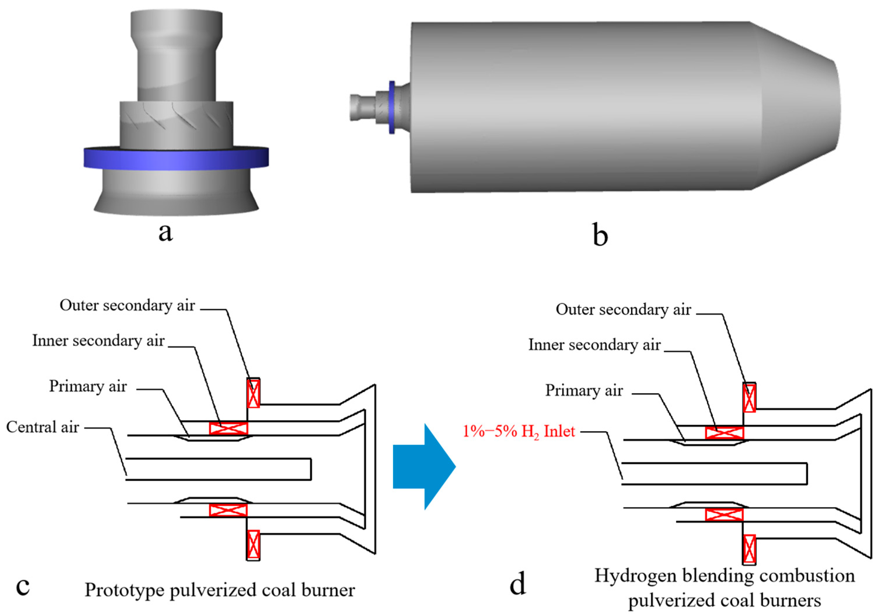
In this study, a single swirl burner in a swirl opposed boiler is used for simulation. First, the simplification of the burner is realized by omitting the parts of the swirl burner that do not affect the operation of the burner. The simplified burner is then modeled 1:1, as shown in Figure 1a. Since this study is based on a single swirl pulverized coal combustor, the angle of the secondary air vanes inside the combustor is 50° and the angle of the external secondary air vanes is 30°. For the purpose of the study, a virtual combustion region is created by creating a cylindrical shape, as shown in Figure 1. The combustion zone has a diameter of 5 m and a length of 10 m (corresponding to the Y-axis direction). In order to avoid the formation of a reflux zone at the outlet of the furnace, a tapering zone with a length of 2.5 m is provided at the outlet of the cylindrical furnace. The staged air sent into the furnace through the burner mainly consists of external secondary air, internal secondary air, primary air, and central air. There is a pulverized coal concentrator in the primary air pipe which is used to form the pulverized coal gas flow with inner thickness and outer lightness, which is beneficial to the stable combustion. Figure 1c,d show the prototype swirl pulverized coal burner. In order to achieve hydrogen blending of the swirl pulverized coal burner, the central air of the central pipe of the prototype pulverized coal burner was replaced with hydrogen, thus enabling the blending of pulverized coal and hydrogen.

Figure 1.
(a) Swirl pulverized coal burner model, (b) combustion chamber model, (c) prototype pulverized coal burner, and (d) hydrogen blending combustion pulverized coal burners.
3. Numerical Simulation
3.1. Numerical Modeling
In this study, the flow field, temperature field, and chemical reaction processes in the furnace during the operation of the burner are simulated using the commercial software ANSYS Fluent 22R1. The combustion process follows the conservation of energy, conservation of mass, and conservation of momentum, and then a suitable mathematical model is selected to simulate the combustion process. The simulation was calculated using a second-order upwind format with the simple algorithm for the pressure and velocity fields [20].
The swirl vanes in the combustor form airflow with high swirl intensity, and in order to obtain accurate results, the RSM model was used to simulate the aerodynamic field near the combustor outlet [21]. Here is the Reynolds stress transport equation:
where : diffusion term; : stress generation term; : pressure strain term; : viscous dissipation term.
where : the turbulent viscosity; = 0.82; = 1.8; : the Kronecker delta; : the turbulent kinetic energy; : the turbulent dissipation rate.
Mutual radiation between particles during fuel combustion is an important mechanism for pulverized coal ignition, and the DO model has wider applicability and can calculate the radiative heat transfer process well [22]. For the medium with absorption, emission, and scattering properties, the radiative heat transfer equation at position and along the direction is:
where : the position vector; : the direction vector; : the direction of heat dissipation; : the length along the way; : the absorption coefficient; : the refractive index; : the heat dissipation coefficient; : Stephen-Boltzmann constant; : the radiation intensity; : ambient temperature; : the spatial solid angle; : the phase function.
The volatile analysis process of pulverized coal is modeled using a two-step competitive model that takes into account the different precipitation rates of volatile fractions at high and low temperatures [23]. The relationship between the mass of pulverized coal and time during the reaction can be described by the following formula:
where : the initial mass of PC; : the proportion of two-step volatilization; : the rate of a two-step reaction; A: the pre-reaction factor; E: activation energy.
The combustion model of pulverized coal is carried out using the PDF model, which can satisfy the general pulverized coal combustion process and the accuracy meets the needs of engineering [24]. The mixture fraction is defined as follows:
where : the element mass fraction of element i; : the mass fraction at the inlet of oxidant; : the mass fraction at the fuel inlet; : the source of gas phase component due to its release from the coal particle; : the user-defined source item.
The trajectory of the particles is carried out using a random tracking model [25]. The equation of motion is described as follows:
where : the particle mass; : the drag coefficient; : the gas density; : the particle surface area; : the velocity of the particle; : the average velocity of the gas phase; : the pulsation velocity of the gas phase; : the acceleration of gravity.
The conversion process of pulverized coal is affected by the blending of hydrogen with pulverized coal. The conversion of pulverized coal–hydrogen mixture combustion on the furnace is not known. Further study is needed on how combustion is affected by partial hydrogen blending in pulverized coal.
3.2. Mesh Settings and Grid Independence
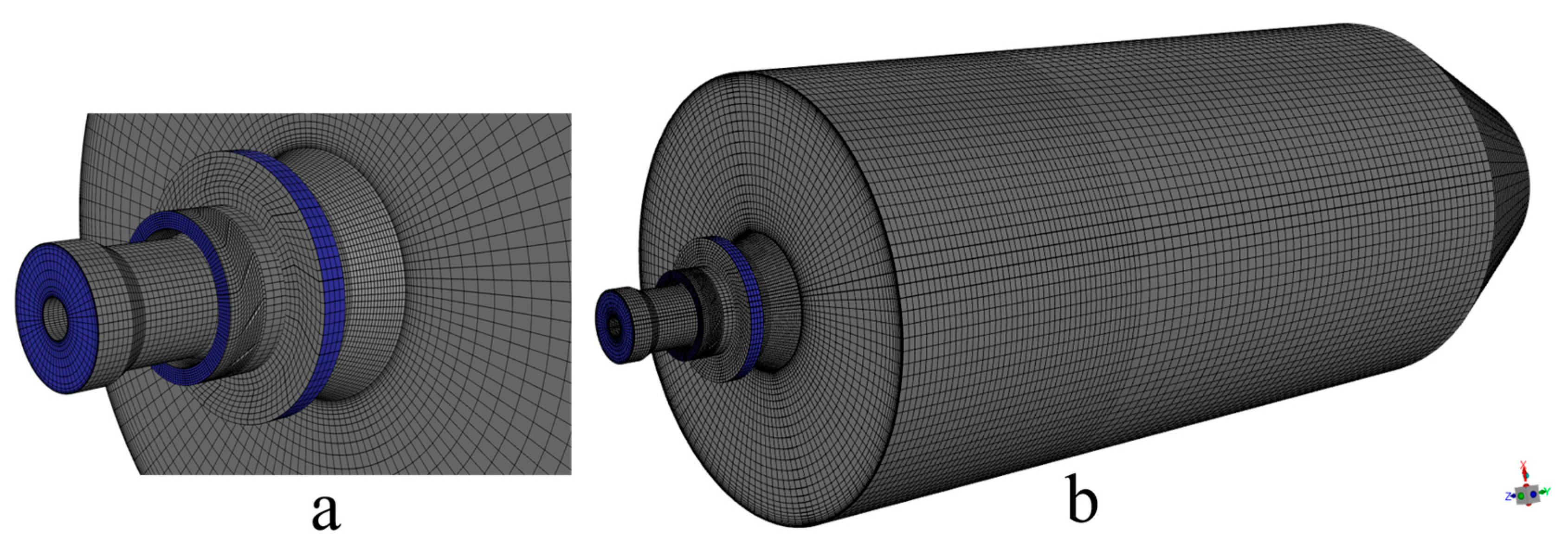
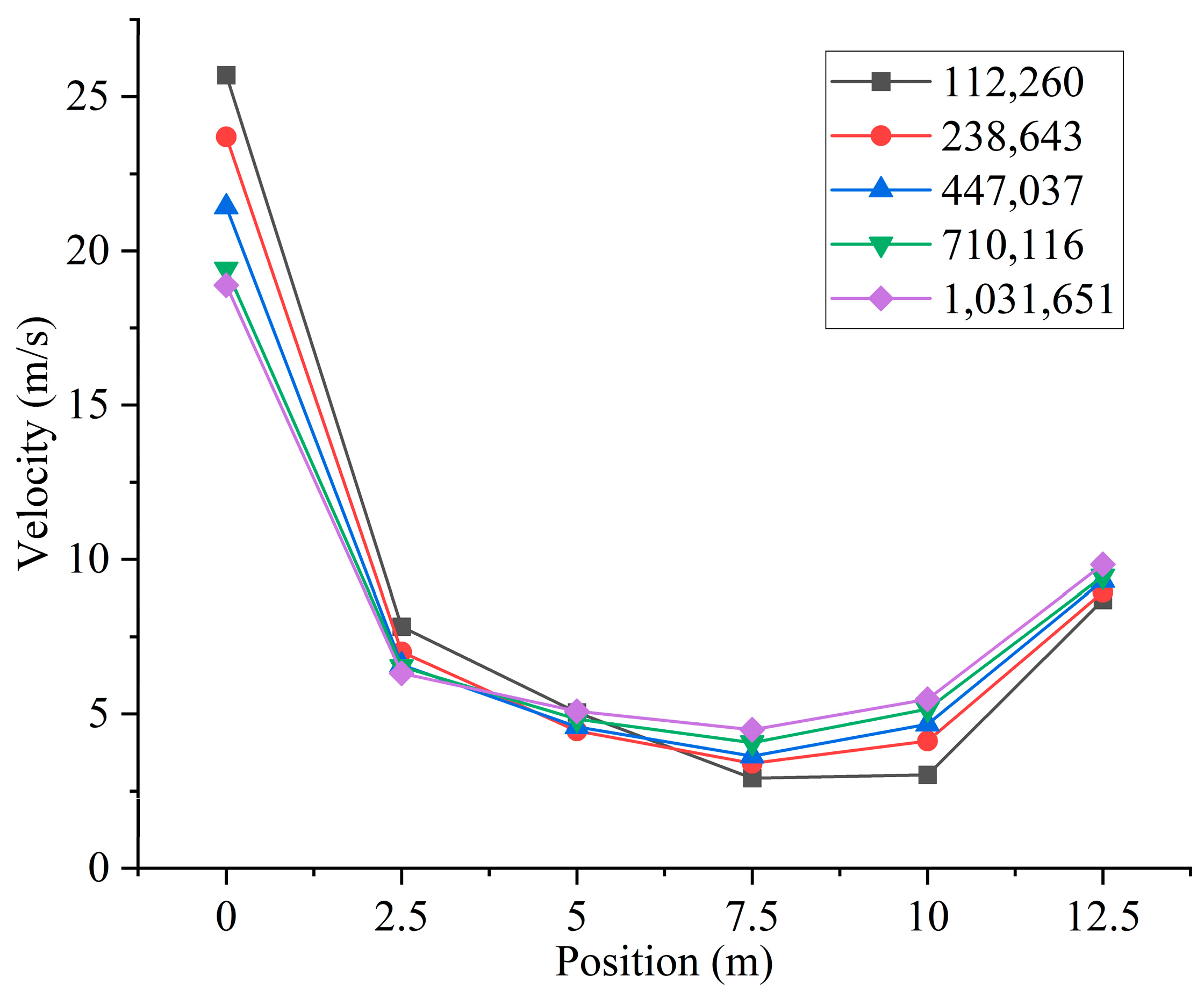
Based on the above simplified burner model, the burner and furnace area are divided into several parts. Then, ICEM is used to generate different numbers of high-quality structured meshes, as shown in Figure 2. In order to ensure the accuracy and improve the efficiency of the calculation, local encryption is performed in the connection area between the furnace and the burner. The grid of the burner part includes the swirl vanes as well as the pulverized coal concentrator. Different numbers of meshes will cause different calculation results. Different numbers of grids will result in different computational accuracy. To minimize the error caused by the number of grids, a total of five different numbers of structured grids, 112,260, 238,643, 447,037, 710,116, and 1,031,651, are used in this study. By measuring the velocity of the cross-section perpendicular to the Y-axis direction of the furnace, the images obtained are shown in Figure 3. Observing the images, it can be found that the velocities of the cross-section at different locations are very close to each other when the number of grids is 710,116 and 1,031,651. Considering the computational volume, the grid number of 710,116 is chosen for the simulation.
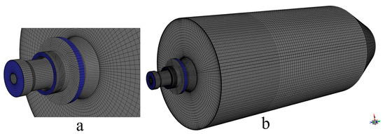
Figure 2.
(a) Mesh of the burner and (b) overall mesh of the computational region.
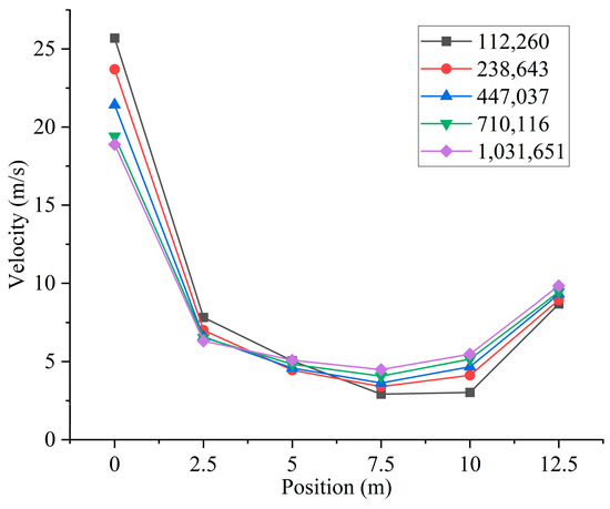
Figure 3.
Different cross-sectional velocities for models with different numbers of grids.
3.3. Boundary Conditions
The coal types used in this study were analyzed as shown in Table 1. The particle size distribution of particles follows the Rosin–Rammler law, and the average particle size of pulverized coal is 53 μm. The inlet boundaries of the burner are all mass inlets. The outlet boundary of the furnace is set to be the pressure outlet to improve the convergence of the calculations. Coal particles rebound after collision with the wall and the trajectory of the particles is changed. The wall boundary condition type was set to Reflect and the wall temperature in the cylindrical combustion zone was 1000 k. The case without hydrogen addition was taken as the basic control group for the study. The gases fed into the furnace through the burner were all air. The inlet parameters of the burner are shown in Table 2. Combustion of pulverized coal by burner alone has been very much studied. However, the combustion mechanism after passing some hydrogen into the pulverized coal is not clear. In this study, pulverized coal is fed through the primary air of the burner and hydrogen is passed through the central air position of the burner. Distributing the air from the central air to the rest of the inlets ensures that the total amount of air required for the combustion of hydrogen and pulverized coal remains constant. The simulation was studied for six different hydrogen percentages (0%, 1%, 2%, 3%, 4%, 5%). The study assumes that the total heat fed into the furnace remains constant. The percentage of hydrogen blending is defined as the proportion of heat input to hydrogen to the total heat input to the furnace, which determines the mass flow rate of hydrogen flux. The central air inlet parameters for different hydrogen blending ratios are shown in Table 3.

Table 1.
Coal quality analysis.
Table 2.
Boundary conditions for basic working conditions.
Table 3.
Boundary conditions for hydrogen blending.
3.4. Model Validation
In order to verify the accuracy of the simulation results, the burner model in the study [26] is used for modeling in this study. Comparison with experimental results for validation, and the verification results, are shown in Table 4. There is an error between the established burner model and the actual model, but the errors after comparing with the experimental results are all within the error range. Therefore, it can be considered that the simulation results can reflect the actual situation of combustion in the furnace.
Table 4.
Comparison of burner simulation value with the experimental value.
4. Results and Discussion
4.1. Analysis of Burnout Rate of Pulverized Coal
Figure 4 shows the pulverized coal burnout rate at the exit of the furnace for different hydrogen blending ratios. The prototype burner operates to achieve stable combustion by swirling and entraining of high-temperature flue gas through the swirl formed by the secondary air. However, the excess air coefficient of the swirl burner was set to be 0.9, and the pulverized coal could not be completely combusted. The burnout rate at the furnace outlet during the operation of the prototype burner was 91.59%. When hydrogen is blended, the amount of solid fuel fed into the furnace is reduced. In addition, the hydrogen gas ignites rapidly and produces a lot of heat quickly, which disturbs the combustion near the burner outlet. The heat released from hydrogen combustion near the burner outlet ignites the fuel, resulting in a 2.36% increase in pulverized coal burnout after blending 1% hydrogen. As the proportion of hydrogen blending increases further, the burnout rate at the outlet of the furnace increases further. The burnout rate of fuel increased by 5.08% with 5% hydrogen.

Figure 4.
Burnout rate of pulverized coal with different hydrogen blending ratios.
4.2. Hydrogen Distribution
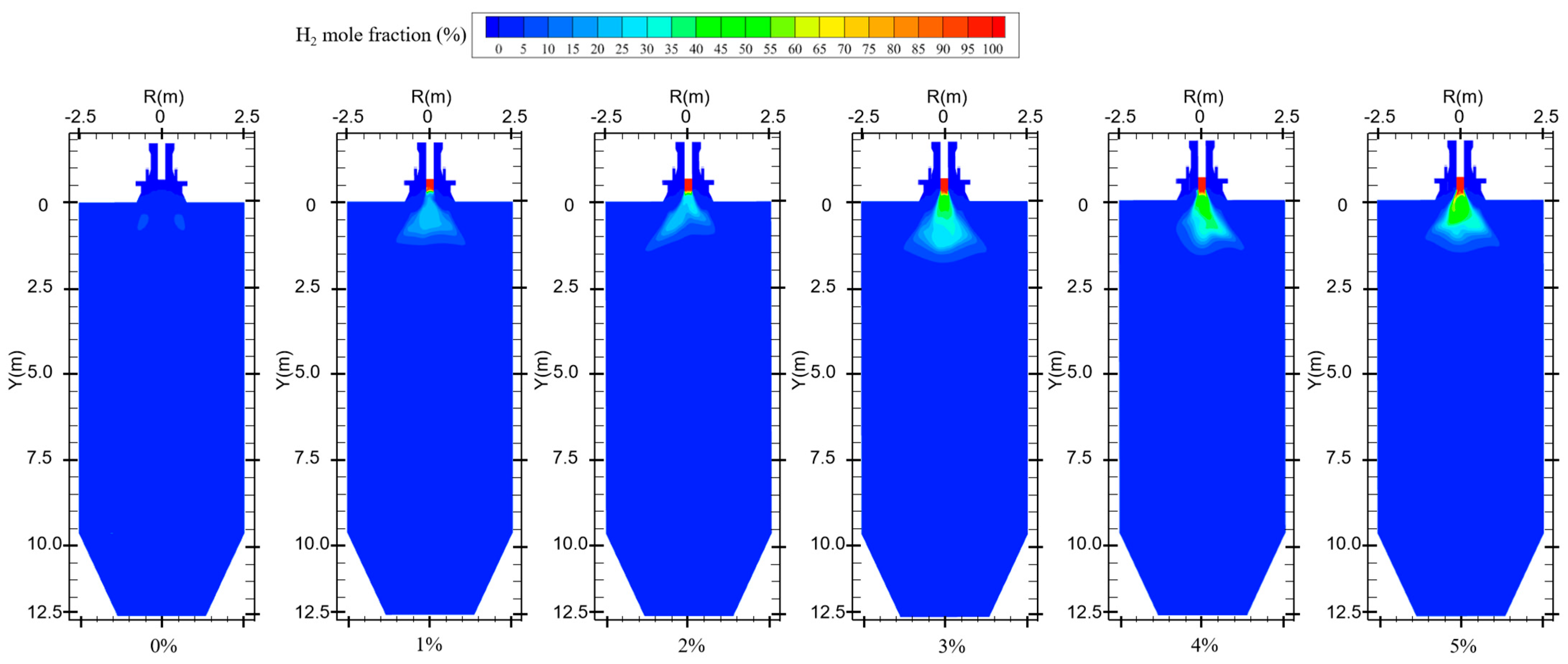
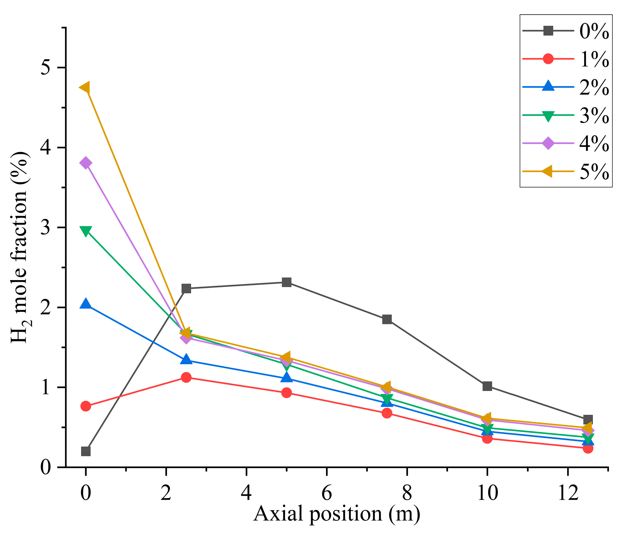
Figure 5 shows the hydrogen distribution at different hydrogen blending ratios. When not passing hydrogen into the furnace, small amounts of hydrogen are generated near the burner outlet. This is mainly due to the fact that, during the combustion process, coal reacts with air and in some cases produces water vapor to generate gases such as H2, CO, and CO2 [27]. Therefore, when hydrogen is not blended, after feeding pulverized coal as fuel into the furnace, the mole fraction of hydrogen shows an increasing trend at the burner outlet to Y = 2.5 m. In Figure 6, when the hydrogen blending ratio is 0%, the hydrogen content along the axial direction in the furnace shows an increasing and then decreasing trend. This is due to the fact that a small amount of water is generated from the combustion of pulverized coal in the furnace [4]. The water reacts with the CO generated from incomplete combustion of pulverized coal in the furnace, thereby generating a small amount of H2 [28]. The reflux zone in the furnace causes this fraction of hydrogen to be consumed in the high-temperature environment after mixing with air, and the hydrogen concentration gradually decreases. When 1% hydrogen is injected into the furnace, the mole fraction of hydrogen at the burner outlet remains low. However, the small amount of hydrogen generated by pulverized coal injection causes the mole fraction of hydrogen near the burner outlet to rise slightly. The effect of hydrogen generated from pulverized coal pyrolysis on the hydrogen content in the furnace is not obvious as the hydrogen blending ratio rises, as shown in Figure 6. When 1% hydrogen is added, hydrogen starts to burn inside the center pipe and the mole fraction of hydrogen starts to decrease inside the central pipe. Continuing to increase the proportion of hydrogen blended, the flow rate of the central pipe rises and more hydrogen is fed into the furnace. Hydrogen mixed with the oxidizer rapidly catches fire in the high-temperature environment and a large amount of hydrogen is consumed. As a result, the concentration of hydrogen is very low in the second half of the furnace.
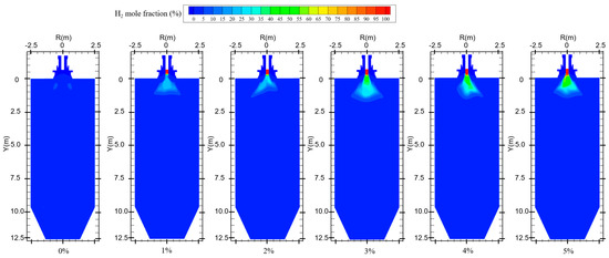
Figure 5.
Hydrogen distribution for different hydrogen blending ratios.
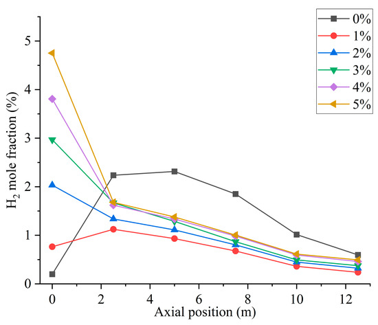
Figure 6.
Furnace axial hydrogen distribution with different hydrogen blending ratios.
4.3. Temperature Distribution
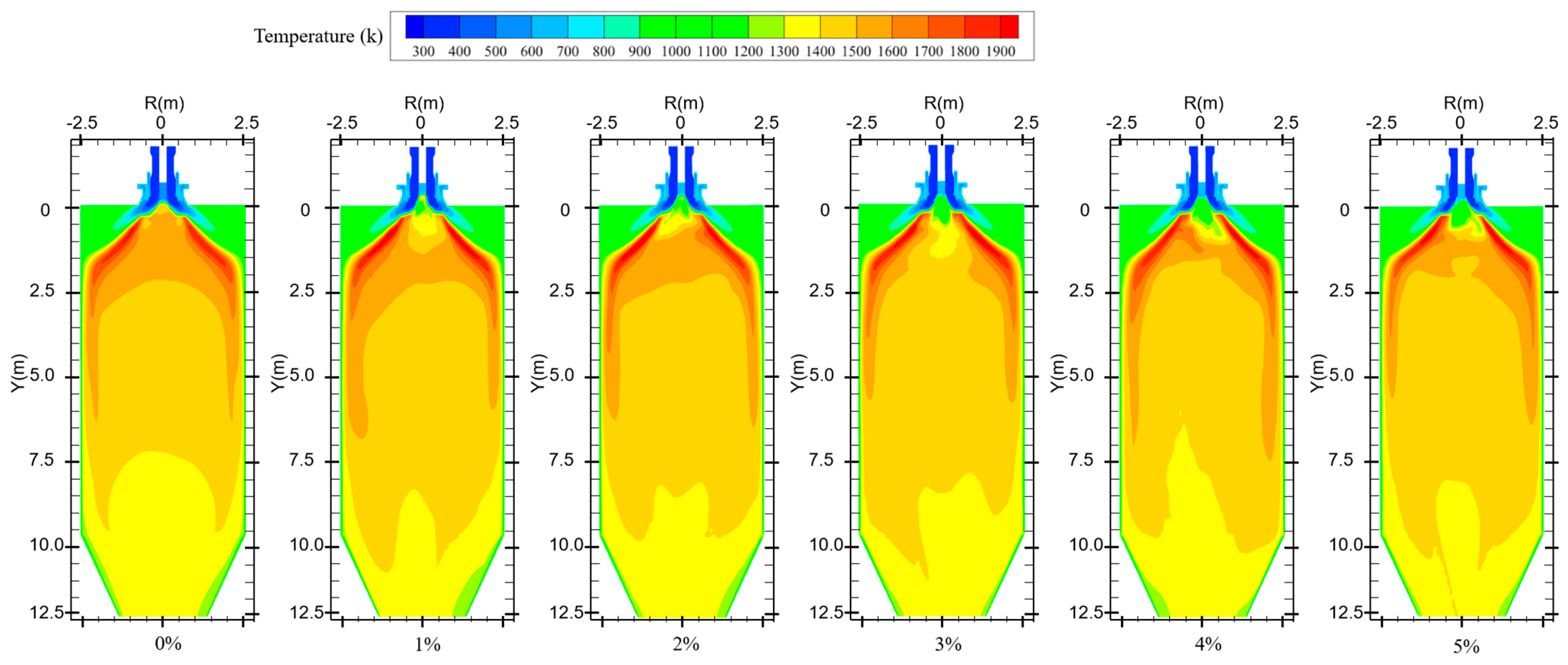
Figure 7 shows the temperature distribution for different hydrogen blending ratios. When no hydrogen is added to the furnace, the pulverized coal is ignited by the high-temperature flue gas in the reflux zone after it is fed into the furnace. Pulverized coal combustion is predominantly distributed in the front end of the furnace chamber with uniform temperature distribution. When hydrogen is added, the flame spreads quickly due to the combustion of hydrogen. Near the outlet of the central pipe, the hydrogen gas mixes with the oxidizer and burns rapidly and consumes a large amount of oxidizer. This makes the fuel at the outlet of the burner lack the oxidant needed for combustion, resulting in the pulverized coal not being able to burn completely. In addition, the water generated by hydrogen combustion will wet the coal powder. During coal combustion, evaporation of water consumes a large amount of heat, resulting in severe heat loss during combustion and lowering of the temperature of the combustion equipment. This creates an area of lower temperature near the burner outlet. The secondary air swirl formed by the burner will entrain some of the hydrogen gas, thus causing the temperature near the wall of the furnace chamber to rise. Observation of the overall temperature distribution found that the overall temperature distribution moved in the direction of the furnace outlet. On the one hand, this is because the water in the pulverized coal absorbs heat due to gasification, which leads to slower combustion rate of pulverized coal, delayed combustion, and less intense reaction. On the other hand, the water generated by hydrogen combustion wets the pulverized coal, and the wet pulverized coal cannot catch fire quickly. This results in a delayed burnout of some of the pulverized coal, and the high-temperature zone moves toward the outlet of the furnace. When hydrogen is added to the furnace, the temperature distribution inside the furnace becomes non-uniform compared to that without adding hydrogen.
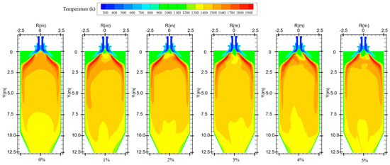
Figure 7.
Temperature distribution in the furnace for different hydrogen blending ratios.
4.4. Combustion Product Distribution
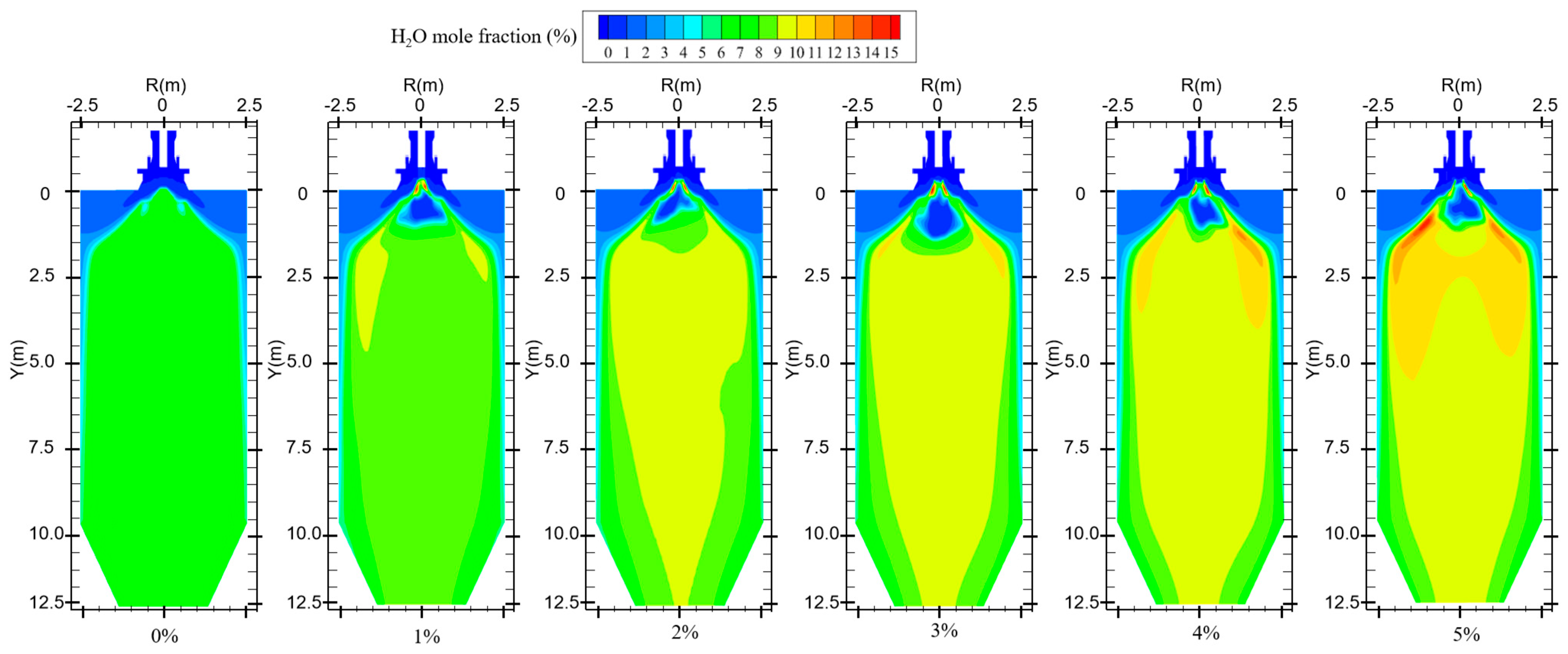
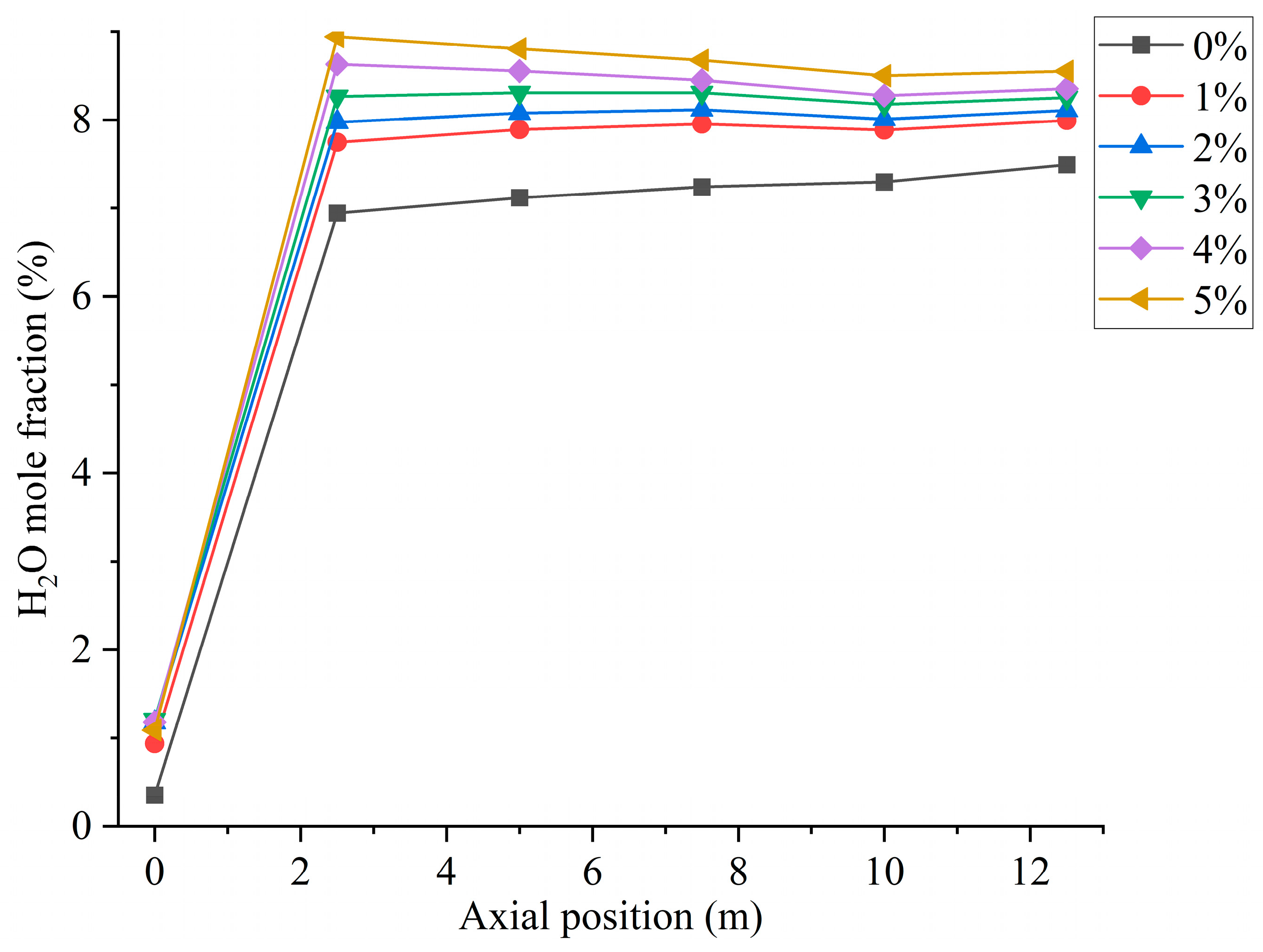
In the combustion process of coal, suitable moisture (5–8%) can effectively help the combustion process, influence the combustion characteristics, and enhance the combustion effect [29]. The boiler will form a high-temperature region inside the furnace during normal operation. When hydrogen is not added to the furnace, primary air carries coal particles into the combustion zone, and the moisture in the pulverized coal evaporates in the high-temperature region. In addition, the pulverized coal enters the high-temperature zone and decomposes at high temperatures, resulting in the precipitation of hydrocarbons. The hydrocarbon combustion generates a small amount of water, which is uniformly distributed in the furnace, as shown in Figure 8. Water is a combustion product of hydrogen. When hydrogen is blended into the furnace, increasing the amount of hydrogen gas fed into the furnace increases the amount of water produced, as shown in Figure 9. However, the secondary air is deflected by the vanes to form a reflux region in the furnace. The water vapor generated by hydrogen combustion is swept up by the reflux region, and the high-concentration region of moisture is concentrated at the front of the furnace and distributed on both sides of the burner.

Figure 8.
Water generation in the furnace with different hydrogen blending ratios.
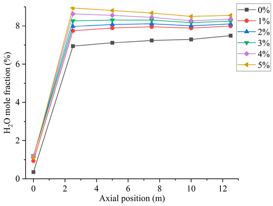
Figure 9.
Furnace axial moisture distribution for different hydrogen blending ratios.
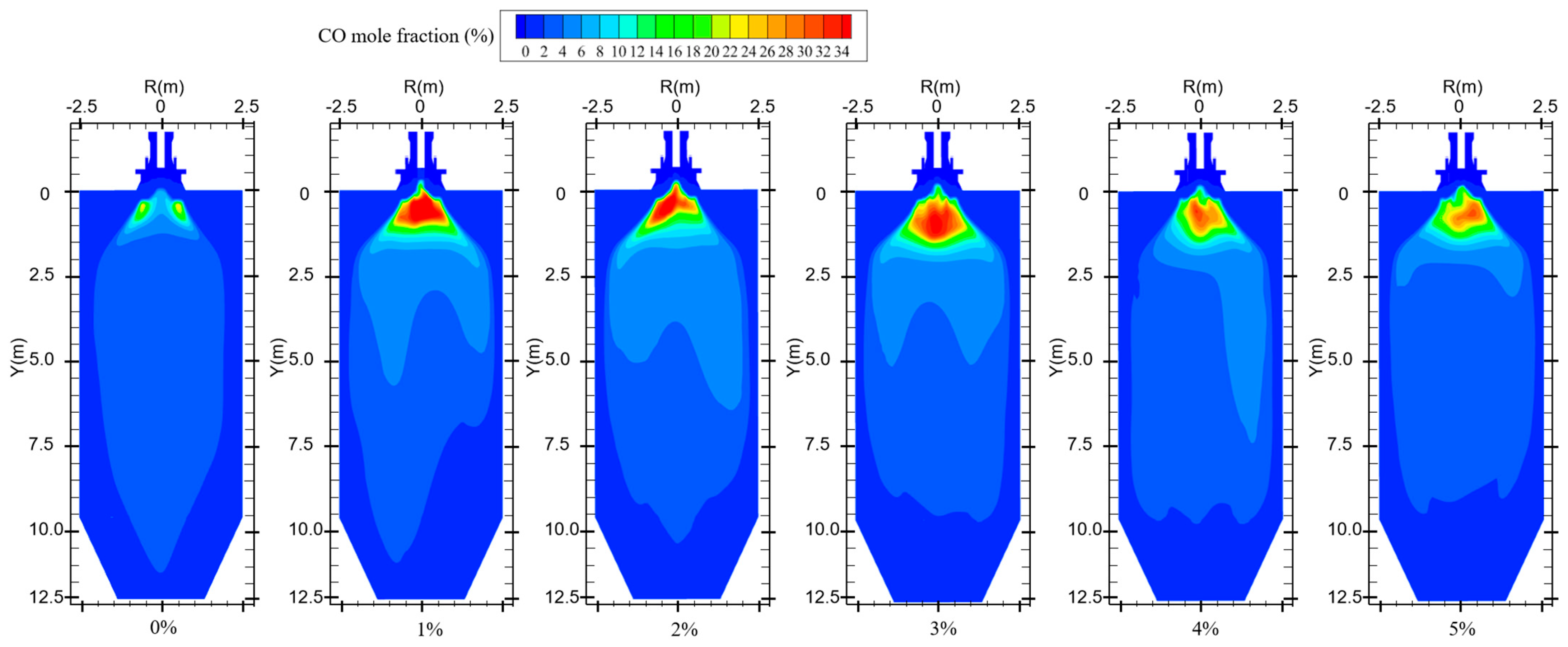
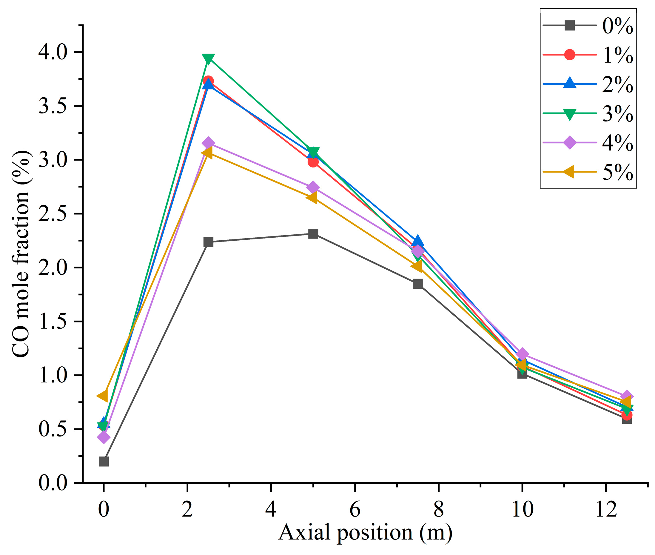
Figure 10 shows the CO distribution for different hydrogen blending ratios. There are two main sources of CO in the furnace. On the one hand, when not feeding hydrogen into the combustion zone, the pulverized coal, which is passed from the primary air pipe to the inside of the combustion zone, starts to burn near the burner and consumes a large amount of oxidant. With a higher concentration of pulverized coal near the burner outlet, part of the pulverized coal cannot be fully mixed with the oxidant. As a result, this part of the pulverized coal cannot be burned completely and a large amount of CO is generated near the burner outlet. After hydrogen blending, hydrogen combustion produces water vapor. The temperature of the primary air inlet is 345 k, which is below the boiling point of water. Therefore, part of the water vapor mixed with the primary air will liquefy to form water and attach to the pulverized coal. In addition, in the high-temperature environment of the furnace, the liquefied water evaporates and absorbs heat at high temperatures, thus reducing the temperature near the burner outlet. These factors affect the complete combustion of the pulverized coal, causing the CO content near the burner outlet to rise. On the other hand, since the combustion process is exothermic, a high-temperature region is formed inside the furnace. Pulverized coal and hydrogen operate in a process of co-combustion. The water vapor generated by the combustion of hydrogen reacts with carbon in a high-temperature environment. This process accelerates the vaporization process of fixed carbon, which leads to the formation of increasing concentration of CO, as shown in Figure 10. As can be seen in Figure 9, When the proportion of hydrogen blending is greater than 3%, and as the proportion of hydrogen blending increases, the temperature inside the furnace rises due to the intense combustion of hydrogen gas. This accelerates the combustion of CO gas, resulting in a reduction in CO generated at the burner outlet. The CO generated near the burner outlet is oxidized to CO2 after mixing with air in the reflux zone, and the CO concentration gradually decreases along the axial direction, as shown in Figure 11. CO pollution is a type of air pollution that can harm human health. Adding hydrogen to the pulverized coal flow causes the CO content in the furnace to rise, which leads to increased CO emissions at the furnace outlet, causing pollution of the environment.

Figure 10.
CO distribution for different hydrogen blending ratios.
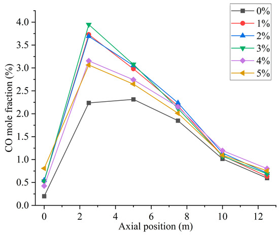
Figure 11.
Furnace axial CO distribution for different hydrogen blending ratios.
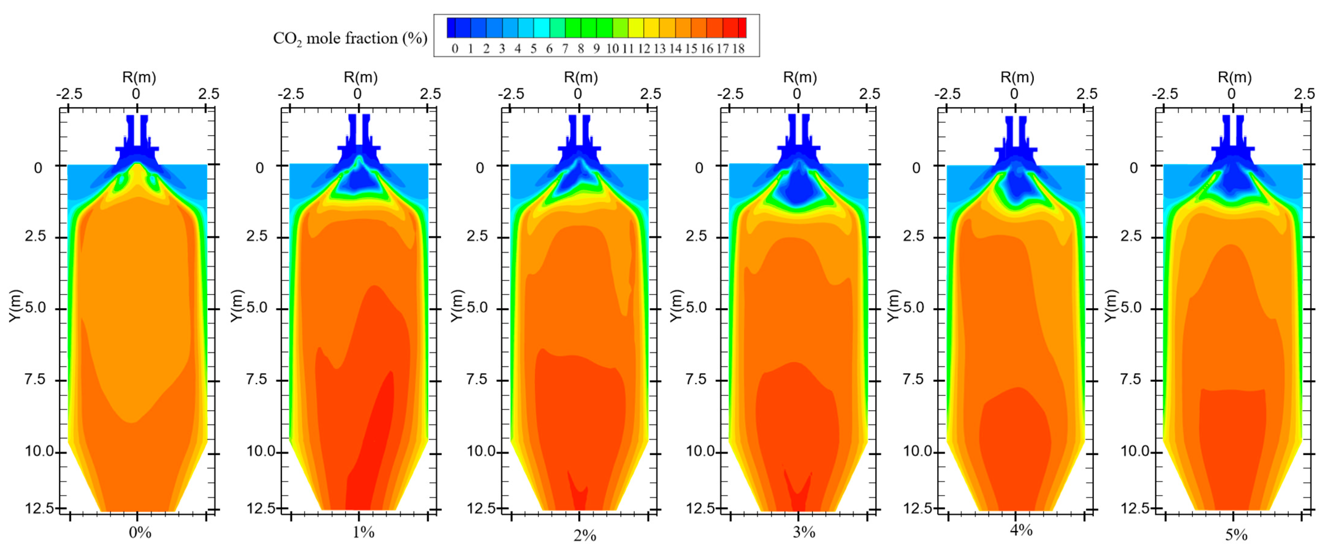
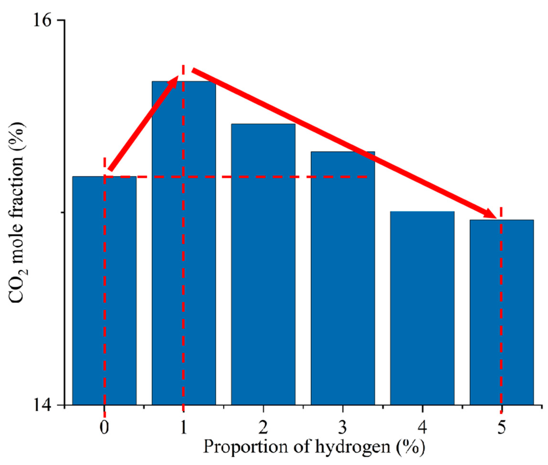
Figure 12 shows the CO2 distribution in the furnace at different ratios. When hydrogen is not added to the furnace, the solid fuel is injected into the combustion zone from the primary air pipe, and the combustion starts near the burner outlet. However, the mixing of pulverized coal and air at the burner outlet is weak, and the pulverized coal cannot be completely burned, generating a small amount of CO2. With the further mixing of the primary and secondary air, the unburned pulverized coal near the burner outlet continues to be burned to generate CO2 by mixing with oxidant. In addition, the CO generated near the burner outlet is oxidized to form CO2. The CO2 concentration gradually increases along the axial direction of the furnace, as shown in Figure 13. Comparison of Figure 10 and Figure 12 shows that areas of high CO concentration correspond to areas of low CO2 concentration. After blending different proportions of hydrogen in the central air pipe of the burner, a conical-shaped region of low CO2 concentration appears at the burner location. On the one hand, this is due to the intense combustion of hydrogen at the burner outlet and the formation of water. At high temperatures, the water vapor reacts with the solid fuel to form a large amount of CO. On the other hand, the oxygen consumed by the rapid combustion of hydrogen causes the pulverized coal to burn incompletely to form CO. When adding 1–3% hydrogen to the furnace, the burnout rate rises. Furthermore, the amount of CO2 generated by burning the increased pulverized coal is greater than the amount of CO2 reduced by hydrogen blending. The CO2 is larger than that of pure pulverized coal combustion, as shown in Figure 14. Hydrogen blending in pulverized coal gas flow utilizes hydrogen of equal calorific value to replace pulverized coal of equal calorific value, thus achieving the goal of reducing carbon emissions. Further increase in the proportion of hydrogen blending results in a decrease in the amount of pulverized coal fed in. The high temperature released by hydrogen combustion enhances the combustion of pulverized coal, which leads to an increase in pulverized coal burnout, as shown in Figure 4. However, an increase in the proportion of hydrogen blending decreases the amount of pulverized coal, which most always leads to a decrease in the total amount of CO2 emissions. When the hydrogen blending ratio is 4% and 5%, the amount of pulverized coal passed into the furnace is reduced, and the high temperature released by hydrogen combustion makes the burnout rate of pulverized coal increase further. When more than 3% hydrogen is added to the furnace, due to the reduction in carbon-containing fuels, CO2 emissions at the furnace outlet are lower than in the absence of hydrogen, as shown in Figure 14. When the amount of hydrogen added is 5%, the CO2 emission at the furnace outlet is reduced by 1.49% compared to the hydrogen blending ratio of 0%, which is a low CO2 reduction. However, the CO2 emission at the outlet of the furnace with 5% hydrogen blending is 3.22% less than that with 1% hydrogen blending. It is expected to achieve lower carbon emissions if the proportion of hydrogen blending continues to increase. Comparing the CO2 distribution with different hydrogen blending ratios in Figure 12, it is found that the CO2 content is higher at the outlet of the furnace. This is because the water vapor generated by hydrogen combustion wets the pulverized coal, which delays the combustion of the pulverized coal. The unburned pulverized coal is concentrated near the outlet of the furnace and generates a large amount of CO2. To reduce CO2 emissions, the burnout rate of pulverized coal can be increased when a lower proportion of hydrogen is added to the pulverized coal flow, thereby increasing the CO2 emission at the furnace outlet. By further increasing the proportion of hydrogen blending, the CO2 emission from the combustion of pulverized coal is less than the CO2 reduction caused by hydrogen blending, and the purpose of reducing CO2 emission is achieved.

Figure 12.
CO2 distribution for different hydrogen blending ratios.
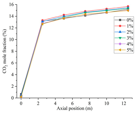
Figure 13.
Furnace axial CO2 distribution with different hydrogen blending ratios.
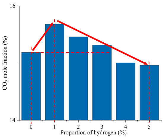
Figure 14.
CO2 emission at the furnace outlet for different hydrogen blending ratios.
5. Conclusions
This paper studies the co-combustion process of hydrogen and pulverized coal through a burner in the combustion zone. The study uses numerical simulation to pass different proportions of hydrogen into the furnace at the central air pipe of the burner. The effects of different hydrogen blending ratios on the flame structure, pulverized coal combustion rate, and combustion products are discussed. The following conclusions were obtained by analyzing the results of the study:
- (1)
- Hydrogen burns and produces a lot of heat to ignite the pulverized coal, resulting in a 2.36% increase in the burnout rate after 1% hydrogen blending compared to combustion without hydrogen addition. The burnout rate of pulverized coal increased by 5.08% after burning 5% hydrogen. The burnout rate increased with the increase in the percentage of hydrogen blending.
- (2)
- When no hydrogen is added to the furnace, a small amount of hydrogen is generated by the reaction of the pulverized coal when it is fed into the furnace. The hydrogen concentration rises near the burner outlet. When different proportions of hydrogen are fed into the furnace, the area of high hydrogen concentration is mainly near the burner outlet. At high temperatures, the hydrogen concentration decreases axially as the hydrogen mixes with the oxidizer.
- (3)
- When no hydrogen is added to the furnace, many of the pulverized coals are concentrated at the front end of the combustion zone, and the temperature distribution is uniform. After hydrogen blending, the water generated by hydrogen combustion wets the pulverized coal. The coal combustion process of water evaporation consumes a lot of heat, reducing the temperature of the combustion equipment, and the burner outlet appears as a low-temperature zone. Hydrogen blending makes part of the pulverized coal combustion time prolonged, and the high-temperature zone moves to the direction of the furnace outlet.
- (4)
- After hydrogen blending, the reflux zone formed by the burner causes the high concentration of moisture to be concentrated in the area near the burner. When the amount of hydrogen added to the furnace is zero, the CO in the furnace mainly comes from the incomplete combustion of pulverized coal. When 1–3% hydrogen is added, the water vapor in the furnace reacts with the carbon to produce a large amount of CO. When more than 3% hydrogen is added to the furnace, the water content rises, resulting in a lower temperature at the burner outlet and a decrease in the amount of CO produced. When the proportion of hydrogen blending is 1–3%, the burnout rate rises, and the CO2 generated by combustion increases. When the proportion of hydrogen blending is more than 3%, the CO2 emission is reduced. The CO2 emission at the outlet of the furnace with 5% hydrogen blending was 1.49% lower than that without blending, and 3.22% lower than that with 1% hydrogen blending.
Author Contributions
Software, C.W.; Validation, W.L.; Formal analysis, X.J.; Investigation, L.D.; Data curation, X.L. (Xiang Lin) and Q.W.; Writing—original draft, X.L. (Xin Lei); Writing—review & editing, H.L. All authors have read and agreed to the published version of the manuscript.
Funding
The funding is provided by the State Grid Company Limited Electric Power Research Institute Science and Technology Project (SGXJDK00NYJS2310296).
Data Availability Statement
Data are contained within the article.
Acknowledgments
The authors appreciate the financial support provided by the State Grid Xinjiang Company Limited Electric Power Research Institute Science and Technology Project (SGXJDK00NYJS2310296).
Conflicts of Interest
Author Xiang Lin, Xuehui Jing, Wei Liu, and Qiaozhen Wang was employed by the company State Grid Xin Jiang Company Limited Electric Power Research Institute. Cheng Wang was employed by the company State Grid Xingjiang Electric Power Co., Ltd. The remaining authors declare that the research was conducted in the absence of any commercial or financial relationships that could be construed as a potential conflict of interest.
References
- González-Torres, M.; Pérez-Lombard, L.; Coronel, J.F.; Maestre, I.R.; Yan, D. A review on buildings energy information: Trends, end-uses, fuels and drivers. Energy Rep. 2022, 8, 626–637. [Google Scholar] [CrossRef]
- Yadav, S.; Mondal, S.S. Numerical modelling of oxy-coal combustion to access the influence of swirl strength, combustion environment and gasification reactions on the flow and combustion behaviour. Combust. Theory Model. 2021, 25, 488–513. [Google Scholar] [CrossRef]
- Yan, R.; Chen, Z.; Zheng, Y.; Yuan, L.; Zeng, L.; Li, Z. Influence of inner and outer secondary air ratio on flow and combustion characteristics of a swirl burner in a 29 MW pulverized coal boiler. Energy 2021, 237, 121625. [Google Scholar] [CrossRef]
- Choi, M.; Park, Y.; Li, X.; Kim, K.; Sung, Y.; Hwang, T.; Choi, G. Numerical evaluation of pulverized coal swirling flames and NOx emissions in a coal-fired boiler: Effects of co-and counter-swirling flames and coal injection modes. Energy 2021, 217, 119439. [Google Scholar] [CrossRef]
- Chen, P.; Fang, Y.; Wang, P.; Gu, M.; Luo, K.; Fan, J. The effect of ammonia co-firing on NO heterogeneous reduction in the high-temperature reduction zone of coal air-staging combustion: Experimental and quantum chemistry study. Combust. Flame 2022, 237, 111857. [Google Scholar] [CrossRef]
- Chen, P.; Jiang, B.; Wang, H.; Gu, M.; Fang, Y.; Wang, P. Experimental and theoretical calculations study on heterogeneous reduction of NO by char/NH3 in the reduction zone of ammonia co-firing with pulverized coal: Influence of mineral Fe. Fuel 2022, 310, 122374. [Google Scholar] [CrossRef]
- Chen, P.; Wang, H.; Jiang, B.; Wang, Y.; Gu, M.; Chen, G.; Huang, X. An experimental and theoretical study of NO heterogeneous reduction in the reduction zone of ammonia co-firing in a coal-fired boiler: Influence of CO. Fuel Process. Technol. 2022, 231, 107184. [Google Scholar] [CrossRef]
- Zhang, J.; Ito, T.; Ishii, H.; Ishihara, S.; Fujimori, T. Numerical investigation on ammonia co-firing in a pulverized coal combustion facility: Effect of ammonia co-firing ratio. Fuel 2020, 267, 117166. [Google Scholar] [CrossRef]
- Ishihara, S.; Zhang, J.; Ito, T. Numerical calculation with detailed chemistry on ammonia co-firing in a coal-fired boiler: Effect of ammonia co-firing ratio on NO emissions. Fuel 2020, 274, 117742. [Google Scholar] [CrossRef]
- Liu, M.; Chen, S.; Zhu, H.; Zhou, Z.; Xu, J. Numerical investigation of ammonia/coal co-combustion in a low NOx swirl burner. Energy 2023, 282, 128358. [Google Scholar] [CrossRef]
- Tamura, M.; Gotou, T.; Ishii, H.; Riechelmann, D. Experimental investigation of ammonia combustion in a bench scale 1.2 MW-thermal pulverised coal firing furnace. Appl. Energy 2020, 277, 115580. [Google Scholar] [CrossRef]
- Lewis, D. Hydrogen and its relationship with nuclear energy. Prog. Nucl. Energy 2008, 50, 394–401. [Google Scholar] [CrossRef]
- Momirlan, M.; Veziroglu, T.N. The properties of hydrogen as fuel tomorrow in sustainable energy system for a cleaner planet. Int. J. Hydrogen Energy 2005, 30, 795–802. [Google Scholar] [CrossRef]
- Elam, C.C.; Padró, C.E.G.; Sandrock, G.; Luzzi, A.; Lindblad, P.; Hagen, E.F. Realizing the hydrogen future: The International Energy Agency’s efforts to advance hydrogen energy technologies. Int. J. Hydrogen Energy 2003, 28, 601–607. [Google Scholar] [CrossRef]
- Fischer, M. Safety aspects of hydrogen combustion in hydrogen energy systems. Int. J. Hydrogen Energy 1986, 11, 593–601. [Google Scholar] [CrossRef]
- Patel, V.; Shah, R. Effect of hydrogen enrichment on combustion characteristics of methane swirling and non-swirling inverse diffusion flame. Int. J. Hydrogen Energy 2019, 44, 28316–28329. [Google Scholar] [CrossRef]
- El-Ghafour, S.; El-Dein, A.; Aref, A. Combustion characteristics of natural gas–hydrogen hybrid fuel turbulent diffusion flame. Int. J. Hydrogen Energy 2010, 35, 2556–2565. [Google Scholar] [CrossRef]
- Gersena, S.; Slima, B.; Zeijlmakera, R.; Van Essena, M.; Tichelaarb, R. The development of a natural gas/hydrogen boiler system. In Proceedings of the the International Gas Union Research Conference, Muscat, Oman, 24–26 February 2020; pp. 1–8. [Google Scholar]
- Li, X. Optimization and reconstruction technology of SCR flue gas denitrification ultra low emission in coal fired power plant. IOP Conf. Ser. Mater. Sci. Eng. 2017, 231, 012111. [Google Scholar] [CrossRef]
- Menni, Y.; Chamkha, A.J.; Zidani, C.; Benyoucef, B. Numerical analysis of heat and nanofluid mass transfer in a channel with detached and attached baffle plates. Math. Model. Eng. Probl. 2019, 6, 52–60. [Google Scholar] [CrossRef]
- Breussin, F.; Pigari, F.; Weber, R. Predicting the near-burner-one flow field and chemistry of swirl-stabilied low-NOx flames of pulveried coal using the RNG-k-ε, RSM and k-ε turbulence models. Symp. Int. Combust. 1996, 26, 211–217. [Google Scholar] [CrossRef]
- Ghose, P.; Patra, J.; Datta, A.; Mukhopadhyay, A. Prediction of soot and thermal radiation in a model gas turbine combustor burning kerosene fuel spray at different swirl levels. Combust. Theory Model. 2016, 20, 457–485. [Google Scholar] [CrossRef]
- Richards, A.P.; Fletcher, T.H. A comparison of simple global kinetic models for coal devolatilization with the CPD model. Fuel 2016, 185, 171–180. [Google Scholar] [CrossRef]
- Wang, Y.; Zhou, Y. Numerical optimization of the influence of multiple deep air-staged combustion on the NOx emission in an opposed firing utility boiler using lean coal. Fuel 2020, 269, 116996. [Google Scholar] [CrossRef]
- Laubscher, R.; Rousseau, P. CFD study of pulverized coal-fired boiler evaporator and radiant superheaters at varying loads. Appl. Therm. Eng. 2019, 160, 114057. [Google Scholar] [CrossRef]
- Shang, T. Experimental Study and Numerical Simulation on a Low-NOx Semi-Anthracite Coal Swirl Burner; Tsinghua University: Beijing, China, 2016. [Google Scholar]
- Wang, S.; Danner, M.; Kuchling, T.; Clarke, M.A. Measurement of the three-phase (vapour+ liquid+ solid) equilibrium conditions of semi-clathrates formed from mixtures of CO2, CO and H2. J. Chem. Thermodyn. 2013, 56, 149–152. [Google Scholar] [CrossRef]
- Westbrook, C.K.; Dryer, F.L. Simplified reaction mechanisms for the oxidation of hydrocarbon fuels in flames. Combust. Sci. Technol. 1981, 27, 31–43. [Google Scholar] [CrossRef]
- Chernetskii, M.Y.; Dekterev, A. Mathematical model for heat transfer and combustion in a pulverized coal flame. Combust. Explos. Shock Waves 2011, 47, 280–288. [Google Scholar] [CrossRef]


Disclaimer/Publisher’s Note: The statements, opinions and data contained in all publications are solely those of the individual author(s) and contributor(s) and not of MDPI and/or the editor(s). MDPI and/or the editor(s) disclaim responsibility for any injury to people or property resulting from any ideas, methods, instructions or products referred to in the content. |
© 2024 by the authors. Licensee MDPI, Basel, Switzerland. This article is an open access article distributed under the terms and conditions of the Creative Commons Attribution (CC BY) license (https://creativecommons.org/licenses/by/4.0/).