1. Introduction
The prevailing global energy mix is predominantly sustained by conventional sources, notably fossil fuels, giving rise to environmentally harmful consequences through the emission of toxic gases. This phenomenon greatly adds to the general concern about global warming and intensifies climate-related issues. A noticeable global trend towards renewable energy alternatives has been seen, in response to environmental requirements and the growing expenses linked with conventional fuel sources [
1]. A global pledge has been made to reach a significant 70% renewable energy consumption by 2030 [
1]. Solar energy emerges as a promising and reliable renewable energy solution in the face of challenges faced by saturated hydroelectric resources and the demanding prerequisites of wind power adoption, such as extended prefeasibility studies, expansive land requirements, significant initial investments, and advanced technological infrastructures. This is especially important for tropical nations, where the plentiful solar resource provides an exceptional opportunity for sustainable and eco-friendly energy generation, addressing both environmental concerns and the specialized energy demands of tropical climatic zones.
In this scenario, a substantial integration of solar power into the grid can give rise to various technical challenges. These challenges encompass low inertia, voltage irregularities, frequency fluctuations, power oscillations, harmonic distortions, a diminished power factor, transient disturbances, flickering, and increased strain on power lines, transformers, and energy storage systems [
2]. Given the intermittent nature of solar electricity, ensuring voltage stability becomes a critical concern for utility providers [
3]. Nonetheless, it is crucial to uphold the voltage to a permissible level to guarantee the safe operation of equipment. Therefore, energy storage systems along with power electronic converters can be utilized to mitigate voltage violation [
4]. Power electronic converters are widely used in renewable energy systems to maintain the output voltage at a constant level [
5]. Buck, boost, buck–boost, and push–pull converters are some basic converters that have been used for decades. Nonetheless, they have some issues that add intolerable ripples to the input current [
6].
Generally, solar energy produces relatively low output voltages that need to be boosted to a certain level. Conventional DC-DC boost converters are simple power electronic devices. Still, they cannot be used in high-power applications due to their low voltage gain and high current ripple and voltage ripple [
7]. Moreover, substantial switching and conduction losses led to poor efficiency in addition to the reverse recovery problem [
6]. As a result, conventional boost converters were modified with various voltage booster circuits/techniques to improve their performance. Magnetic coupling, the voltage multiplier circuit, the switched inductor and voltage lift technique, the multi-stage/level, and the switched capacitor (charged pump) are some available techniques that can be used to boost the voltage further [
8,
9].
As a voltage-boosting technique, magnetic coupling is a suitable option because it offers a lot of possibilities for design freedom [
10]. It also offers high efficiency in soft-switched types and low conduction losses since the switches can be designed on the LV side. Its ease of adjustment also makes it attractive [
11]. Thus, it can be widely used in high-power applications, DC microgrids, and regenerative, as well as bidirectional, applications. Nonetheless, this approach has limitations, such as enormous dimensions, leakage inductances, and significant voltage spikes [
8,
12].
Additionally, the voltage multiplier technique is appealing due to its ability to handle high voltages, structure, and integration with various other converters. However, it requires many cells for the HV application and causes more stress on components [
8,
13]. Moreover, switch inductors and voltage lift circuits are also used in large-gain DC-DC boost converters due to their excellent boost capability and ability to integrate with many converters. Nevertheless, this is not recommended for high-power applications, and they need more passive components [
8,
14].
In addition to single-level boost converters, multi-level boost converters are widely used in renewable energy systems because they offer a high power density, high-quality output voltage, high efficiency, high voltage-to-current ratio, compatible structure, low switching losses, lower harmonic distortion, large voltage gain without an extreme duty cycle, and high switching frequency [
15]. However, controlling this converter is extremely difficult and requires an external balancing circuit since they do not provide a voltage balance for the DC link [
16]. Additionally, the large number of components makes this converter relatively bulky in size [
8,
13]. The switched capacitor/charge pump circuit is also commonly used in high-gain DC-DC applications due to its merits, such as its low cost, compactness, weightlessness, high power density, and fast response time. The major drawback of this option is the lack of output voltage regulation [
8,
14].
The quadratic boost converter is another option that can be formed by cascading two conventional boost converters [
17]. Here, the quadratic function of the duty ratio gives the voltage gain value. Thus, this limited voltage gain restricts this converter from high-power applications [
18]. Also, high ripples in the input current support the demerits of this converter [
8,
9,
10,
11,
12,
13].
This study aims to fill a significant research gap by concentrating on the unexplored domain of three-phase interleaved boost converters directly connected to Li-Ion batteries without the incorporation of a charging circuit. The existing literature predominantly focuses on conventional boost converters or their modifications, leaving space in the exploration of three-phase interleaved boost converters in this specific configuration. Addressing this gap, this research introduces and investigates a novel configuration, sorting out an underrepresented area of power electronics. Furthermore, this investigation extends to the often-neglected aspect of loss analysis in three-phase interleaved boost converters. While efficiency is commonly mentioned in the context of conventional boost converters, detailed loss analysis, particularly considering inductor copper loss and semiconductor conduction loss in the proposed system, remains less common in the literature. This research aims to bridge this gap by providing a comprehensive examination of the losses associated with the proposed configuration, contributing valuable insights to the field of power electronics and converter design.
Interleaved boost converters (IBCs) are outstanding in addressing the limitations of traditional boost converters, particularly in high-power applications. Their parallel configuration enhances their performance, making IBCs increasingly popular. In high-power scenarios, IBC deployment is essential, offering benefits such as ripple reduction, an improved conversion efficiency, reliability, a minimized filter component size, reduced stress on switching elements, and an increased power density [
6,
19,
20].
This study explores a 3Ph-IBC with an energy storage system for a solar power generation unit. Furthermore, the performance of the converter and controller is investigated using numerical simulations at various irradiance and temperature levels. A charging circuit is typically employed to connect batteries to a DC link. In contrast, the Li-Ion battery is directly connected to the DC link in this design. Additionally, a three-phase voltage source inverter (VSI) is deployed to transfer the generated energy to the AC grid using MATLAB Simulink. Finally, a detailed loss analysis was carried out to investigate the effect of parasitic losses in a 3-Ph-IBC.
The main contributions of this investigation are as follows:
A three-phase IBC with Li-ion battery integration;
The integration of a current control fuzzy logic controller with an MPPT for a 3-Ph IBC;
Loss analysis for a 3-Ph IBC.
Overall, this research introduces a novel and comprehensive solution to address technical challenges in solar power integration, presenting a three-phase interleaved boost converter with unique features and providing a detailed analysis of its performance and efficiency.
The following is an outline of this article:
Section 1 discusses several existing DC-DC converters, the motivation, and the main contribution.
Section 2 covers the converter circuit description and mathematical modeling, the controller, and the energy storage system.
Section 3 provides simulation results and discussion.
Section 4 focuses on the impact of inductor internal resistance and semiconductor devices on the efficiency of the 3Ph-IBC and power losses. Finally,
Section 5 presents the conclusion based on a thorough examination of the obtained simulation results.
2. The Design of the Interleaved Boost Converter
The following section describes the design of the interleaved boost converter.
2.1. Proposed System Description and Mathematical Modeling
The 3Ph-IBC has proven to be the best multi-phase IBC due to its numerous benefits [
21,
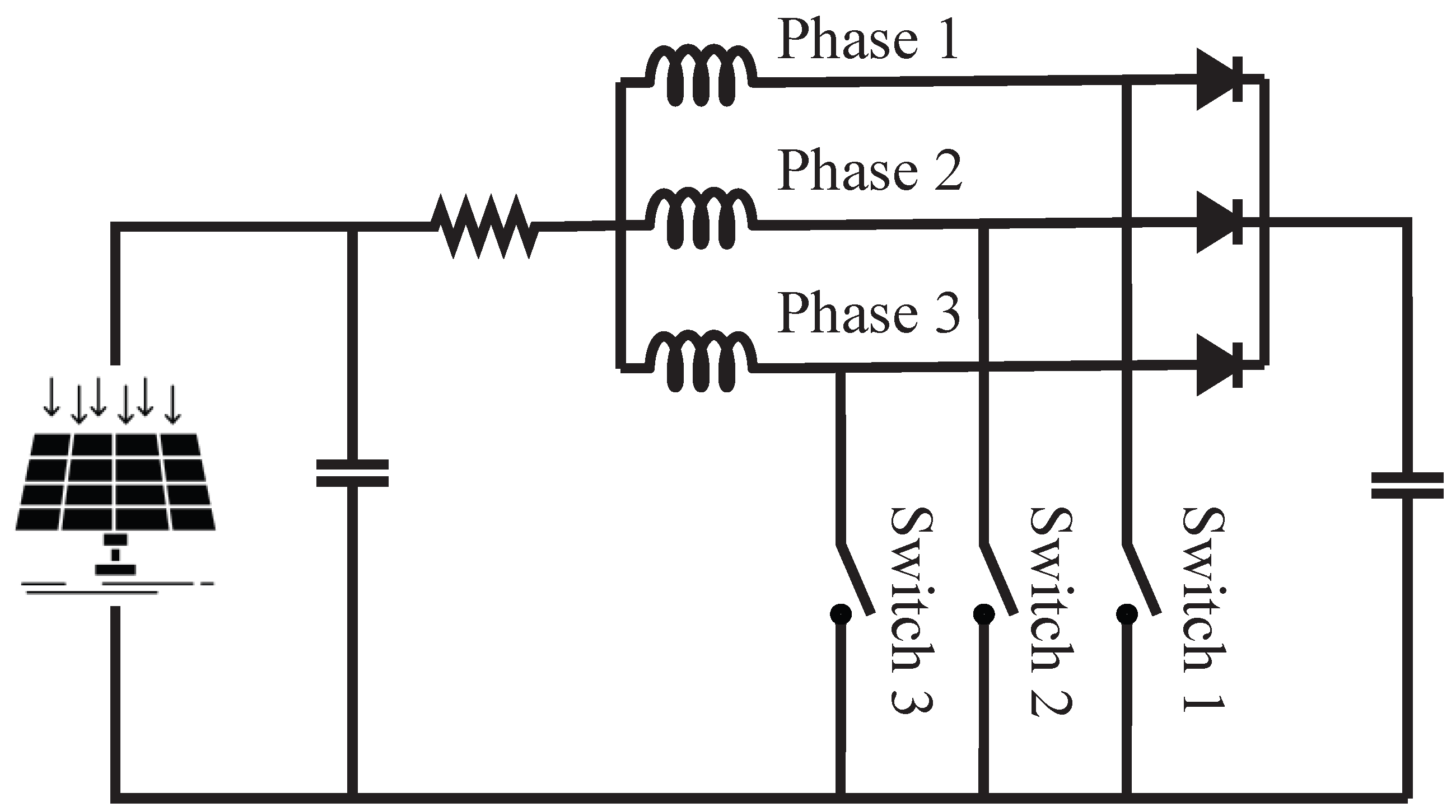
22]. A schematic of a simple three-phase interleaved boost converter is shown in
Figure 1. In this case, the converter’s input has three conventional boost converters in parallel, each consisting of an inductor, a diode, and an IGBT switch. The design and simulation of the converter and associated systems are executed using the MATLAB Simulink platform. It is important to note that this study primarily concentrates on the integration of the converter with the battery storage and the mathematical modeling and design of the variable source inverter fall outside the scope of this study at the moment.
The specifications of the selected solar module are shown in
Table 1.
PV Array Modeling:
The SolarTech Universal PERCB-W-285 model was used for the simulation.
The 3Ph-IBC is designed for a 5 kW power rating and a 10 kHz switching frequency. It tries to stabilize the output voltage at 400 V, delivering a dependable and constant power supply. To minimize fluctuations and ensure a smooth power delivery, the intended output voltage ripple is restricted to 1%, and the input current ripple is meticulously maintained at 5%.
When designing the solar PV system, the operating voltage range of the system was initially determined. The panel string output voltage should be within this range. The maximum module voltage is related to the lowest ambient temperature.
The lowest expected ambient temperature was considered to be 25 °C in this study. Furthermore, the NOCT was assumed to be 44 °C, and the maximum temperature was calculated as 54 °C. By substituting the provided values from
Table 1 into Equations (
1) and (
2), the operating voltage range of the solar PV module was calculated to be 28.84 V and 39.38 V, respectively.
Further, to obtain the design specifications, nine modules per string and two parallel connected strings are selected to have the 5 kW rated output according to Equation (
3).
Calculations for the components:
Equations (
1)–(
9) were utilized to calculate the converter parameters for the simulation model. The values obtained are shown in
Table 2 below.
When a converter operates in discontinuous conduction mode (DCM), the efficiency can be impacted negatively. The DCM introduces additional switching losses due to the discontinuity in the inductor current. The efficiency reduction is generally associated with increased conduction losses and potentially higher peak currents. For the three-phase interleaved boost converter, maintaining a continuous conduction mode is necessary to obtain the most power from the PV panels.
Furthermore, the Li-Ion battery is directly linked to the converter output/DC connection, eliminating the need for a separate charging circuit. Consequently, it is guaranteed that the DC link voltage remains constant. A three-phase voltage source inverter is further attached to the DC link for the purpose of converting the DC to AC and transmitting electricity to the AC grid. A block diagram of the whole system is shown in
Figure 2.
2.2. Controller
To optimize the converter’s dynamic performance, closed-loop controllers can be employed. Due to their simplicity, PI/PD/PID controllers are frequently used. However, the core issue with the PID contoller is that it is challenging to adopt and achieve the greatest performance when utilized with a non-linear system. In addition, it influences output voltage regulation and requires exact linear mathematical modeling [
23]. Fuzzy logic controllers, in comparison to conventional controllers, provide superior precision and an enhanced performance under transient situations. Also, they provide a reliable performance while regulating the output voltage without the requirement for precise mathematical models [
24]. Therefore, the fuzzy logic controller is adopted for this design in this study.
Furthermore, when integrating a solar system, it is critical to discuss MPPT controllers since solar energy is intermittent and temperature- and insolation-dependent. Hence, it is crucial to guarantee that the power generation is always at its maximum, regardless of the state of the atmosphere. Because of this, a maximum power point tracker (MPPT) was utilized in this design to generate the maximum power under various environmental circumstances. The hill–climbing algorithm/Perturb and Observe method (P&O Algorithm) has been selected for MPPT implementation even though there are many other options available [
25,
26]. A P-V curve and a flowchart for a hill–climbing algorithm are shown in
Figure 3 and
Figure 4, respectively.
In this hill-climbing algorithm, the PV current and voltage are sent into the MPPT controller where it calculates the power, change in power, and change in voltage to deliver an output as a reference voltage. This reference voltage could be used to calculate the reference current for the closed-loop current controller. A comparison of the 3Ph-IBC output current with this reference current generates an error signal. The error signal and the error signal change are then supplied to the fuzzy inference system to generate a switch control signal. To create switch pulses, the triangular carrier signal is compared to the switch control signal. The controller is shown in
Figure 5.
2.3. Energy Storage System
A Li-Ion battery is connected across the converter terminals in the proposed architecture. Since the battery serves as a source, the converter’s output voltage is always fixed. In this case, the charging current for the energy storage is determined by substituting the values of the power and converter output voltage into Equation (
5). However, the ultimate objective is to draw the maximum energy from the solar panel. Since the converter’s terminal voltage is constant, the converter’s output current should be controlled by changing the duty factor. The PV current and PV terminal voltage must be monitored in the MPPT control scheme to sense the power extracted from the PV module. The reference current is calculated from this power and compared to the feedback current, which is the output of the 3Ph-IBC. In this way, the current mode fuzzy logic controller is used to connect the battery to the DC link directly.
Furthermore, a current controller is highly advised for direct battery connections. The battery is a voltage source, and the PV module-connected converter also works as a controlled voltage source if the voltage is regulated. As there is no series impedance between the two in such a case, a high circulating current flows through the controlled source. Thus, a current-based controller must be implemented and combined with the MPPT controller to provide a duty factor to achieve the ultimate goal.
The primary goal of this battery storage system is to meet the peak demand. Also, when solar energy production is poor, this battery may be utilized to supply the energy to the grid. This battery is beneficial for adjusting the voltage as well as functioning as a backup power source in the case of a system breakdown.
This battery bank is designed to provide 2 kWh energy each day. Moreover, the load subsystem efficiency, including the round-trip battery efficiency, wiring loss, and conversion efficiency, needs to be considered as no battery is efficient. Further, the round-trip efficiency is assumed to be around for Li-Ion batteries, and this loss estimate is simply based on the chemistry of the battery. In addition to that, wiring losses that may occur as the current flows between the battery and the converter are also considered. It is better to combine all these losses into a single factor in this case.
We will multiply
for round-trip efficiency by
for wiring losses by
for conversion efficiency, and this provides an overall subsystem efficiency of
. Further, in this case, we will select 3 days of autonomy, which should provide sufficient reserve power for our application. Additionally, a temperature coefficient factor also needs to be included in the calculation, as the battery capacity will typically drop at lower temperatures. Next, the depth of discharge (DoD) describes how far down the battery can be drained. In this design, it is kept as
to avoid complete discharge. The total usable battery capacity is given by
where TUBC is the total usable battery capacity, DD is the daily demand, DoA is the days of autonomy,
is the temperature coefficient,
V is the voltage, LSE is the load subsystem efficiency, and MDOD is the maximum depth of discharge.
In this case, 34 batteries with terminal voltages of 12 V are connected in series to provide a nominal voltage of 408 V, which is closer to the recommended 400 V. Furthermore, the battery state control algorithm is designed to ensure that the SOC is kept between and . To prevent a depth of discharge during failures, the band’s bottom margin is retained at a maximum of .
It is extremely important to select a good algorithm to regulate the charging and discharging of the battery because we developed this battery without a charging circuit. Overcharging is not permitted in a battery. Thus, it is necessary to guarantee that the battery is not overcharged while still ensuring a long operating life without interfering with the system’s performance [
27]. The state control method is illustrated schematically in
Figure 6, which also reveals the operating modes of the Li-Ion battery.
3. Simulation Results and Discussion
The simulation results are provided in this section to validate the operation of the proposed converter. The MATLAB Simulink platform was utilized to design the converter in this case, and the simulation results are discussed further below.
The output voltage and ripple level are shown in
Figure 7a. In this instance, the measured ripple voltage is 0.51 V, or 0.125%, greatly exceeding our expectations. The target output ripple is 1%. Additionally,
Figure 7b–d serve as evidence for the fact that the converter’s input voltage, solar panel output power, and insolation are all subject to variations over time. It is more than sufficient to confirm the MPPT controller’s functionality.
Furthermore,
Figure 8 shows switch pulses generated by the three switches, each of which is 120 degrees phase-shifted. In
Figure 9, the inductor current ripple waveforms for three phases vary between
V and
V, accounting for
V of peak-to-peak ripple. Further, it is
of the input current, which is less than the specified value of
.
Figure 10 depicts the diode current waveforms for three diodes with a peak-to-peak ripple of 1 A. Additionally,
Figure 11 illustrates the voltage stress on switches for the three phases.
The findings of the simulation verify the operational integrity of the suggested converter and offer information on its performance that is consistent with the objective of this research. Achieving a ripple voltage of 0.51 V, below the 1% target, demonstrates the converter’s efficacy in maintaining stable output characteristics. Dynamic variations in the input voltage, solar panel output power, and insolation, as depicted in
Figure 7b–d, underscore the converter’s adaptability to real-world conditions, supporting the motivation to address technical challenges in solar power integration.
Additionally, the detailed analysis of critical components, including switch pulses, inductor current ripple, diode current waveforms, and voltage stress on switches, validates the converter’s robustness under various operating conditions. The consistent adherence to design specifications and the mitigation of ripple effects align with the identified research gaps, emphasizing the significance of the proposed converter in addressing issues associated with voltage violation, frequency fluctuation, and energy storage in solar power systems. Overall, the simulation results support the aims and highlight the converter’s potential to accelerate the shift to efficient and reliable renewable energy alternatives.
4. Loss Analysis
The interleaved boost converter’s voltage gain must increase with the increase in the duty cycle, but this is typically not the case because of parasitic losses. This section explains how parasitic losses and converter efficiency change as elements such as inductors, diodes, and transistors change.
The 3Ph-IBC is only taken into consideration for loss analysis here due to its simplicity. Rather than connecting to a solar panel, a simple DC voltage supply is connected to the converter’s input and boosted to a constant 400 V via closed-loop voltage control fuzzy logic control for this loss analysis.
Furthermore, loss analysis was performed in four different scenarios, with one parameter changing while the others remained constant. First, the series inductor resistance was varied for three phases to investigate inductor copper loss and semiconductor conduction losses. The input voltage, or gain, was then varied to determine the efficiency relationship. Afterward, by varying the switching resistance, semiconductor conduction losses were investigated. Finally, the converter’s efficiency was investigated under various load conditions by varying the load without changing the cumulative impedance value (the total load impedance is ).
Evidently, the inductor copper loss shows a linear escalation concerning the inductor resistance value, as depicted in
Figure 12a. Notably, the semiconductor conduction loss follows a similar trend, increasing alongside higher inductor resistance values, as observed in the same image. Consequently, the efficiency decreases with increasing resistance levels, as seen in
Figure 12b.
In
Figure 13a, the inductor copper loss exhibits an upward trend with increasing gain values. This observation leads to the conclusion that maintaining lower gain values is preferable to mitigate inductor copper loss. Similarly,
Figure 13b illustrates an increasing trend in semiconductor conduction loss with gain values, considering switches and diodes collectively for simplicity. The collective rise in the inductor copper loss and semiconductor conduction losses with gain values indicates a decrease in efficiency. This deduction is affirmed by the findings in
Figure 13c.
The influence of switch resistance on inductor copper losses is apparent from the approximately declining trend observed in
Figure 13d. With an increase in switch resistance, semiconductor conduction losses exhibit fluctuating waveforms in
Figure 13e, and, similarly, the waveform in
Figure 13f reflects the resultant reduction in overall converter efficiency. Despite waveform changes, the overall trends in
Figure 13e,f show an increase in semiconductor conduction losses and a fall in efficiency.
Figure 13g shows that changing the output resistance does not affect the inductor copper loss. Finally,
Figure 13h,i show how the semiconductor conduction loss and converter efficiency vary with the output resistance while maintaining a constant cumulative output impedance of
.
5. Conclusions
Our research efforts concluded in the detailed design and study of a three-phase interleaved DC-DC boost converter linked with an energy storage system, specifically adapted for a 5 kW solar power generation unit. The system is implemented using MATLAB/Simulink and connects with the grid through a three-phase voltage source inverter. The direct connection of the Li-ion battery to the DC link, which eliminates the need for an additional charging circuit, distinguishes this study from other studies.
This study adds a new perspective to the current literature by including a detailed loss analysis that sheds information on the converter’s efficiency. In addition to adding to the expanding body of knowledge in power electronics, the aforementioned approach demonstrates the design’s originality and practicality in the three-phase interleaved DC-DC boost converter.
This study includes both steady-state analysis and simulation, demonstrating how well the converter performs in meeting predetermined objectives, especially in reducing voltage violations. The simulation results show substantially decreased voltage fluctuations, confirming the efficiency of the technology. Moreover, the thorough loss analysis yields an impressive minimum observed efficiency of almost 93%.
In addition to technical considerations, the research focuses on the system’s dynamic performance, with the controller smoothly calibrated to elicit appealing dynamics. This approach not only tackles voltage-related difficulties but also assures the converter’s ability to handle dynamic conditions. Currently, we are actively working on the experimental design and practical implementation, with the aim of presenting comprehensive results in our follow-up publication.

 ,
, 


