Abstract
Based on air-, water-, and ground-source heat pump systems, a novel type of heat pump system, named the heat-source tower heat pump system (HSTHPS), has recently been developed in the southern area of China. The HSTHPS overcomes the evaporator frosting problems of the air-source heat pump system (ASHPS) when the ambient temperature is lower, and it avoids the geological condition constraints of the water- and ground-source heat pump systems. However, studies on the HSTHPS are insufficient, thereby limiting its development and applications. Thus, the present review provides a detailed literature review on the advancements of HSTHPSs in China, including the HSTHPS operation principle, heat-source tower (HST) structure, heat and mass transfer characteristics, HSTHPS performance, antifreeze solution use, and antifreeze solution regeneration. Studies on the heat and mass transfer characteristics of HSTs are sufficient for guiding the application. Regarding open systems, the solution drifting to the air needs to resolved, and future studies need to focus on structure optimization for heat exchangers in closed systems. Moreover, advanced defrosting technology should be applied to closed-type HSTs, and a suitable operation strategy for HSTHPSs should be developed. Future priorities should involve integrating HSTHPSs with additional renewable energy in order to achieve continuous, stable, and efficient heating in winter based on the characteristics of local climate and renewable energy.
1. Introduction
Nowadays, heat pump systems, mainly, air-source and water/ground-source heat pumps, are utilized for heating and cooling in buildings. However, both heat pump systems face challenges from the surrounding environment, which affect the operation efficiency and hinder the potential for the systems to be broadly used. The operation efficiency of the air-source heat pump system (ASHPS) is significantly reduced when the ambient temperature and humidity are decreased. Furthermore, ASHPSs fail to operate safely under a certain temperature and humidity range, as frost may form on the evaporator surface [1,2]. The performance of the water/ground-source heat pump system (W/GSHPS) is primarily affected by geological conditions. The imbalance of the thermal heat extracted from and released to the soil during the heating and cooling period reduces the operation efficiency and leads to potential unsafe operation [3,4,5].
Based on the air-, water-, and ground-source heat pump system, a novel type of heat pump system, named the heat-source tower heat pump system (HSTHPS), has recently been developed in southern China, providing both heating and cooling options for buildings. According to studies by Xu et al. [6] and Zhang et al. [7], the HSTHPS has exceptional prospects in China, as it may overcome the evaporator frosting problems of the ASHPS and avoid the geological condition constraints of the W/GSHPS. To offer active references and guidance for the follow-up investigation and promotion of the HSTHPS, the present review provides a detailed literature review of the recent advances of HSTHPSs in China, including the HSTHPS operation principle, heat-source tower (HST) structure, heat and mass transfer characteristics, HSTHPS performance, antifreeze solution use, and antifreeze solution regeneration.
2. Description of the HSTHPs
2.1. Structure and Operation Principle of HSTHPs
As shown in Figure 1, the HsTHPS is mainly composed of a Heating-Source Tower and a heat pump unit (HPU). The HST is the absorption device that absorbs heat from ambient air. In winter, the antifreeze solution with a freezing point below 0 °C is utilized as the HST medium to extract the low-temperature heat from the air. The medium flows into the evaporator of the HPU and releases the low-temperature heat via the reverse Carnot cycle. This feature of the HSTHPS allows the air to release not only sensible heat but also latent heat from the condensation of water vapor in the air, indicating that the HSTHPS possesses potential in humid areas. In summer, when the HST medium is replaced by water, the HST connects with the condenser of the HPU to realize better heat dissipation. From the perspective of a heat source, the HSTHPS is one type of an ASHPS. Compared to the traditional ASHPS, the only difference is that the HSTHPS includes a heat transfer between the HST medium and ambient air. Based on the HPU type, the HSTHPS is also a derivative of the W/GSHPS [8].
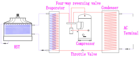
Figure 1.
Schematic configuration of HSTHPs.
2.2. Antifreeze Solution Used in HST
The key for extracting low-temperature heat from the air in winter is utilizing a low-freezing point medium as the HST medium. Therefore, the freezing point must be less than the lowest ambient temperature and limited within the safety threshold during the working time of the HSTHPS [9]. Currently, there are two antifreeze solution types used in HSTs, namely, chloride solutions and alcohol compound solutions. Chloride solutions are inexpensive, as they use low-cost chloride compounds as solutes, such as CaCl2, MgCl2, and LiCl. However, the main integrant of chloride solution, Cl−, causes metal corrosion. To prevent this side effect, extra dichromate must be mixed into antifreeze solutions to act as a corrosion inhibitor. Alcohol compound solutions, including ethyl alcohol, glycerin, and glycol, have weak corrosivity but are relatively expensive [10,11]. Some reports [7,12,13,14] have indicated the use of an alternative solution, with nitrogen urea as a solute, for the HST, which has a mass concentration of 15% and is suitable for the operation temperature range of −20–60 °C. Compared to using water as the medium, the density and viscosity of other antifreeze solutions are increased, but the specific heat capacity is decreased. Therefore, to deliver the same amount of heat, the mass flow rate of the antifreeze solution must be higher than that of water, which inevitably increases the power consumption of the circulation pump [9].
2.3. Description of HST
Different from other types of heat pump systems, the HST is the distinctive component of the HSTHPS, and its structure determines the type of HSTHPS. According to the direct or indirect exposure of the HST to air, the HST and HSTHPS have two types, namely, open and closed. Recent engineering applications and research have improved the structures [12,15,16,17,18]. The structures of various HSTs are illustrated in Figure 2.
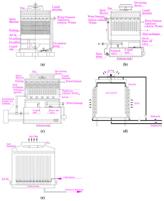
Figure 2.
Different structures of HSTs: (a) open HST; (b) closed HST; (c) improved HST; (d) open HST with pre-condensation; and (e) open HST with upward spraying and non-packing.
2.3.1. Open HST
The structure of an open HST is similar to the traditional cooling tower. In winter, the antifreeze solution, which has a temperature lower than the wet-bulb temperature of ambient air, flows from the evaporator of the HPU to the HST and is sprayed on the packing surface, which forms a liquid film on the top of the packing surface. When the air flows over the packing surface, heat and mass transfer processes occur between the liquid film and air. The antifreeze solution returns to the evaporator and transfers the low-temperature heat to the HPU. In summer, the open HST works in a cooling tower mode. Currently, counter-flow and cross-flow HSTs are two existing open HST types according to the flow direction of air [19,20,21,22].
As shown in Figure 2a, an open HST has a moderately simple structure and allows direct contact between the antifreeze solution and the air, which leads to the advantages of low cost and high heat transfer efficiency. However, the simple structure has potential safety problems. Under high humidity conditions in winter when the water vapor in the air continuously condenses, the concentration of the antifreeze solution decreases, which leads to an increased freezing point. For the open HST to maintain the freezing point of the antifreeze solution, a solute needs to be added into the antifreeze solution, or the HST needs to be equipped with a solution regeneration device. Conversely, the water in the solution evaporates under the low humidity condition, which increases the solution concentration [8,12,23]. Additionally, the open structure also leads to the solution drifting to the air, resulting in serious environmental pollution issues. For example, it has been reported that 4 tons of chloride are emitted into the air every year for every 10,000 m2 of buildings [24]. Furthermore, when chloride solutions are utilized as the HST medium, increased dissolved oxygen causes more severe metal corrosion.
2.3.2. Closed HST
The closed HST was developed based on a closed cooling tower. Instead of using packing like in an open HST, a closed HST adopts an indirect contact method, which requires the antifreeze solution to flow inside a finned tube heat exchanger first and then exchange the heat with the air via the tube surface. Although the indirect contact method fails to maintain the same heat exchange efficiency and low cost as compared to the direct contact method, it avoids the solution loss issue and prevents oxygen dissolving into the solution via the heat and mass transfer processes, which are two major challenges in the direct contact method. In winter, particularly under low-environmental-temperature operational conditions, the temperature of the external surface of the finned tube heat exchanger may be lower than 0 °C when the antifreeze solution absorbs the heat of the high humidity air. In other words, the external surface of the finned tube heat exchanger may be frosted. To avoid frosting, it is necessary to spray a defrost solution onto the external surface of the heat exchanger during operation. The defrost solution located on the external surface of the finned tube is exposed to the air, resulting in a small amount of solution loss and concentration changing issues of the defrost solution. To improve the performance of the closed HST, a solution regeneration device is required [12]. Of note, the fin space in a closed HST is designed to be wider than that of a traditional cooling tower for frost inhibition [25].
In summer, similar to the open HST, water serves as the cooling medium of the closed HST. Basically, cooling water flows inside of the tube to release heat to the air. In addition to the air-cooling effect, to further reduce the temperature of the cooling water, extra water is sprayed onto the external surface of the finned tube, which removes more heat away while it evaporates.
2.3.3. Improved HST
In consideration of the advantages and disadvantages of both the open and closed HSTs, researchers have developed improved HSTs. The most representative improved HST is the one derived from a closed HST (Figure 2c). This improved HST integrates the advantages of open and closed HSTs, and it minimizes the deficiencies of both HSTs. In brief, the packing layer and cooling water spray systems are installed above the top of the finned tube heat exchanger. Moreover, the defrost solution spray unit for frost inhibition is flipped over and installed underneath the bottom of the finned tube heat exchanger, switching the spray mode for the defrosting solution to an upper spray mode from a lower spray mode. The upper spray mode effectively prevents the defrost solution loss and solution concentration change issues under the closed HST operation mode in winter, and it also maintains the high heat exchange efficiency under the open HST operation mode in summer [12].
Considering that the existing open HST has a high moisture absorption rate in winter, which affects the safety of the system, a novel HST structure with a pre-condensation function has been proposed by Xia et al. and Sun et al. [15,16,17] (Figure 2d). This improved HST consists of an open HST and a finned coil tube installed on the side of the open HST and close to the inlet of the air. The antifreeze solution first flows into the finned coil tube to condense the vapor, which is then sprayed onto the packing unit of the open HST (in this case, valve 1 and valve 3 are opened, but valve 2 is closed). This structure type not only reduces the hygroscopic capacity of the solution inside the HST via condensing the water content of the air outside the HST but also expands the heat transfer area and increases the overall heat transfer amount via adding a finned coil tube. Similarly, a tube heat exchanger with a wider fin space is also adopted in this HST for the purpose of frost inhibition. When the air temperature reaches its lower threshold or its humidity exceeds the maximum threshold, the antifreeze solution operates under an open HST mode and transfers heat directly with air (in this case, valve 2 is open, but valves 1 and 3 are closed).
Cui et al. [18] developed another improved HST based on the classic open HST (Figure 2e). This improved HST integrates an upper spray unit for the defrost solution but removes the packing unit, which overcomes the challenges caused by the usage of saline solution, such as salt deposition and the blockage of the tube. Notably, this upgraded open HST costs much less due to the removal of the packing unit. However, this system extends the time for the heat and mass transfer between the solution and air, and it effectively improves the efficiency of the system as the upper spray mode allows the sprayed solution droplets to travel upwards first and then downwards.
3. Performance Research on HST
3.1. Open HST
3.1.1. Heat and Mass Transfer Characteristics
In summer, the open HST functions as an open cooling tower for releasing heat to the air. In winter, the overall heat absorbed by the open HST is the sum of the sensible heat and the latent heat. The sensible heat is caused by the temperature difference between the antifreeze solution and the air, while the latent heat is produced by the evaporation and condensation of water in the air. According to the relative relationship between the temperature of the antifreeze solution and wet air, the following three common cases of heat and mass transfer processes can occur [26,27]: (1) if the temperature of the antifreeze solution is lower than the dew point temperature of wet air, the water vapor contained in the wet air is condensed, which is then mixed with the antifreeze solution, thereby increasing the water content in the antifreeze solution and the heat energy transfer, including the sensible and latent heat transfer, from the air to antifreeze solution; (2) if the temperature of the antifreeze solution is equal to the dew point temperature of wet air, only sensible heat is released to the antifreeze solution from wet air, causing the water content of wet air and antifreeze solution to stay the same; and (3) if the temperature of the antifreeze solution is higher than the dew point temperature but lower than the wet-bulb temperature, only part of the sensible heat released by the wet air is absorbed by the antifreeze solution, and the rest of the released sensible heat is wasted due to the evaporation of the water content in the antifreeze solution, resulting in an increased wet air temperature due to the decreased water content of the antifreeze solution. Thus, the closer the temperature of the antifreeze solution is to the wet-bulb temperature, less heat will be absorbed by the antifreeze solution. When the temperature of the antifreeze solution reaches the wet-bulb temperature, the absorbed heat by the antifreeze solution is almost near zero.
Significant differences also exist in the heat and mass transfer processes between the two operational modes, namely, the heat absorption mode and the heat dissipation mode [21]. Firstly, under the heat dissipation mode, a small portion of the water content inside the formed liquid film of the antifreeze solution evaporates and turns into water vapor, which reduces the liquid film thickness and the thermal resistance of the water. The heat loss during this process is usually negligible, as it rarely affects the overall heat efficiency of the HST. However, in most cases under the heat absorption mode, the water vapor in wet air condenses into water, which penetrates the formed antifreeze liquid film and is added into the solution. As a result, the liquid film becomes thicker, further leading to the non-negligible increase in the thermal resistance of the waterside. Secondly, heat dissipation in summer is mainly achieved by water evaporation, and the heat transfer process is dominated by latent heat transfer, which accounts for more than 80% of the total heat transfer and sometimes reaches as high as 100%. However, the percentage of the latent heat transfer in the heat absorption mode is lower than that of the heat dissipation mode. The water content of the air will not condense until the air temperature becomes lower than the dew point temperature, indicating that the sensible heat transfer is higher than latent heat transfer. When water vapor condenses, the surface tension of the liquid film decreases, and the liquid film becomes unstable and fragile. Thinner liquid films and slower flow rates result in more rapid water temperature increases, causing the formation of a surface tension gradient, which results in less stable liquid films and a reduced latent heat transfer.
3.1.2. Basic Mathematical Model of Heat and Mass Transfer Processes under the Heat Absorption Mode
Under the heat absorption mode, heat and mass transfers occur between the solution and air in the open HST where they can directly contact each other.
For the air side, the transferred sensible heat is determined as follows:
where Qx is the transferred sensible heat, kJ/kg; G is the wet air volume, kg/s; c is the specific heat at the constant pressure of air, kJ·(kg·°C)−1; h is the sensible heat transfer coefficient between air and the surface of the liquid, W·(m2·°C)−1; t is the air temperature, °C; tb is the temperature of the air boundary layer, °C; and A is the area of heat and mass transfer, m2.
The transferred mass is represented with the following formula:
where m is the transferred mass, kg; hmd is the moisture transfer coefficient of air and the solution surface according to the moisture content difference, kg·m−2·s−1; d is the main air moisture content, kg; and db the is moisture content of the air boundary layer, kg/kg.
Therefore, the latent heat exchange amount is represented with the following formula:
where Qq is the transferred latent heat, kJ/kg; and r is the latent heat of vaporization of water at a temperature of tb, kJ/Kg.
Ultimately, the total heat transfer is represented by the following equation:
For the solution side, the total heat transfer equation is written as follows:
where mw is the mass flow rate of the solution, kg/s; cw is the specific heat capacity of the solution at a constant pressure, kJ·(kg·°C)−1; and tw is the solution temperature, °C. Additionally, dm is equal to dmw, for the change of the mass flow rate of the solution is caused by the condensation of water vapor in the air.
3.1.3. Related Study
Counter-Flow Type
According to the climate conditions of tropical and subtropical regions, Tan et al. [28] established the basic mathematical model of heat and mass transfer processes of a counter-flow open HST based on the standard Merkel equation of a cooling tower. Because the thermal resistance of liquid film cannot be ignored during heat absorption, the average temperature of air and water is used in Tan’s model to replace the temperature at the air–liquid interface. Tan et al. later improved the model to allow the calculation of the state parameters of air and water at any positions inside the HST, demonstrating that this model can reliably evaluate the thermal performance of the counter-flow open-type HST [29]. Of note, Tan et al. used water as the working medium of the HST because the ambient air temperature is always above 0 °C in tropical and subtropical regions.
Based on the premise of the Lewis law, She et al. [27] and Liu et al. [30] deduced the general equations for the heat and mass transfer processes of the counter-flow open HST. The equations include eight independent parameters, namely, the inlet temperature, outlet temperature, air humidity, inlet temperature of working fluid, outlet temperature of working fluid, NTU of HST, and liquid/air ratio. The liquid/air ratio is used to indicate the mass proportional relation between air and the working fluid. In theory, if four parameters are known, the other four parameters can be obtained by employing these equations.
Zhang and Wu [19,31] suggested that the model developed by Tan that used the enthalpy difference at the air–water interface as the driving force of heat and mass transfer processes only indirectly reflects the heat and mass transfer processes. Moreover, heat and mass transfer processes exist under low ambient temperature when the Lewis number is equal to one. Therefore, these researchers developed a simplified analysis model, which uses the temperature difference and moisture content difference as the driving force of heat and mass transfers. The new model is more general and easier to apply, but the calculation error is slightly higher than the model proposed by Tan et al. If the inlet temperature of the water and dry-bulb temperature are fixed, the outlet temperature of the water and thermal efficiency of HST can be determined by the water/air ratio and the wet-bulb temperature of the inlet air, wherein the former has much broader impacts. If the inlet parameters of air are definite, the amount of heat absorption and the efficiency of HST is mainly determined by the inlet solution temperature of the air and the liquid/air ratio. Under the condition of the low inlet temperature of the solution and high liquid/air ratio, the amount of heat absorption of HST increases, but the thermal efficiency decreases. Wu et al. [32] suggested that the increase in the inlet air flow rate significantly improves the heat and mass transfer rates but reduces the proportion of latent heat transferred.
Lu et al. [33] generated a heat and mass transfer model for a counter-flow-type open HST, in which the Lewis number is considered. Both theoretical and experimental results show that increases in the dry-bulb temperature significantly increases the sensible heat transfer but slightly reduces the latent heat transfer. In addition, increasing the moisture content of air clearly increases the latent heat transfer and slightly decreases the sensible heat transfer. Increasing the air flow rate increases both the sensible and latent heat transfers but decreases the percentage of the latent heat transfer. Conversely, both sensible and latent heat transfers are decreased if the inlet temperature of the solution is increased. When the inlet temperature of the solution is above 0 °C, the latent heat transfer can be negative, suggesting that increasing the solution inlet temperature is beneficial to solution regeneration. In addition, increasing the solution flow rate also increases the heat transfer rate. However, the increasing rate gradually slows down. The model can also analyze the impacts of packing spacing and pore size on the thermal behavior of the HST. Increasing the packing spacing or decreasing the pore size decrease both the sensible and latent heat transfer rates, with the former having a greater effect.
Cross-Flow Type
The heat and mass transfer processes in a cross-flow open HST differ from those in a counter-flow open HST. The theoretical state of the air and solution varies along with both the vertical direction of the solution flow and the horizontal direction of the wet air flow. Due to the decreases in the temperature difference for both directions, the air temperature at the solution outlet is higher than that at the solution inlet, but the solution temperature at the air inlet is higher than that at the air outlet [31].
Researchers have performed many theoretical and experimental studies on the heat and mass transfer processes of cross-flow open HSTs. Based on the POPPE model, Wen et al. [21] established a verified model of heat and mass transfer processes for cross-flow open HSTs. The average temperature of air and water is used to replace the temperature at the liquid–gas interface. The average air moisture content and the moisture content corresponding to the liquid temperature are employed as the moisture content at the liquid–gas interface. The percentage of the latent heat transfer to total heat transfer in a cross-flow open HST is lower than 35%, and it decreases with the increased inlet solution temperature until a negative percentage is achieved. Wen et al. [34] also studied the percentage of latent heat, moisture content difference of inlet/outlet air, and total heat transfer under different inlet parameters; they suggested that the increases in air volume and inlet air temperature reduce the percentage of latent heat but increase the total heat transfer, whereas an increase in solution volume augments both the latent heat percentage and total heat transfer. However, an increase in solution volume also increases the amount of water absorbed by the solution, which changes the control and regeneration of the solution concentration. Wen et al. [35] conducted theoretical and experimental studies on the heat transfer coefficient between liquid and air in a cross-flow open HST; they reported that the flow rate of liquid and air significantly affects the heat transfer coefficient but has a small effect on the inlet temperature. The correlation formula of the heat transfer coefficient can be acquired by regression as shown by the following equation:
where Ga is the air flow rate, m3/h; Gs is the liquid flow rate, m3/min; and Ta and Ts are the temperature of the air and liquid, respectively, °C. The relative error of the outlet temperature between the measured and computed values is less than 3%.
Huang et al. [36,37] constructed an experimental system of a cross-flow open HST using a glycol solution as the working medium, and they investigated the influences of air volume, temperature, moisture, solution temperature, and solution concentration on the heat transfer coefficient without the premise of the Lewis law. Using the correlation equations of the heat and mass transfer coefficients, as shown in Equations (7) and (8), Huang et al. reported that the heat transfer coefficient is mainly affected by the air mass flow rate of air and solution spraying density, with a Lewis number ranging from 0.91 to 1.12. The correlation equations of the heat and mass transfer coefficients are as follows:
where La is the mass flow rate of air, kg·m−2·s−1; and Ls is the mass flow rate of liquid, kg·m−2·s−1.
Wen et al. [38] investigated the influence of the liquid/air mass ratio on the heat transfer of a cross-flow open HST, using water and a glycol solution as the medium; they reported that the optimal liquid/air mass ratio is between 0.25~0.4 in winter but between 1.33~1.67 in summer because the enthalpy difference between inlet and outlet air is small in winter, indicating that a larger air volume is needed to absorb the same heat transfer amount. Wen et al. [39] also indicated that the HST meets indoor heating demands by optimizing the mass ratio in the transition seasons. In another study, Wen et al. [22] suggested that the HST design mainly meets the demands in winter based on the contrast test of the heat transfer of a cross-flow open HST in winter and summer, demonstrating that the heat transfer rate in summer is four times of that in winter under the same operating conditions.
LÜ et al. [40] studied a plastic porous corrugated plate packing that has a large specific surface area with holes in its surface. According to the analysis of their study, the mesh structure of the porous corrugated packing promotes the cross-flow of liquid film on both sides of the packing and perturbation of the liquid film surface, which further enhances the heat transfer coefficient. Wang et al. [41] presented a mass and heat transfer model for the cross-flow air source heat transfer equipment, using corrugated cellulose paper with excellent hydrophilic properties. These researchers proposed an ε-NTU method for heat transfer enhancement to solve the problem of low inlet air temperature caused by low heat collection. Based on this method, the filling layer is split when ε reaches 67%, which increases the heat collection efficiency by 34% because the split filling layers increase the temperature difference between the solution and the air.
Liang et al. [42] investigated the effect of non-uniform liquid distribution on heat and mass transfer processes in a cross-flow open HST under different fluid mass flow rate and air volume; they reported that an inverted “U” curve correlation exists between the total heat transfer and the uniformity coefficient of liquid distribution. Higher uniformity coefficients of liquid distribution result in reduced total heat transfer.
Additionally, Wu et al. [43] conducted experimental studies on the change law of the Lewis number in a cross-flow open HST, and they reported that the Lewis number increases with increasing mass liquid/gas ratios. When the mass ratio is fixed, the Lewis number decreases with increasing inlet water temperature and wet-bulb temperature but increases with increasing the dry-bulb temperature and liquid spray density. To investigate the non-linearity of effects of factors on heat and mass transfer coefficients in a cross-flow open HST, Wu [20,31,44] utilized the neural network algorithm to predict the performance of a cross-flow open HST without giving heat and mass transfer coefficients, and the experimental data confirmed the reliability of the method.
3.2. Closed HST
3.2.1. Heat and Mass Transfer Characteristics
In summer, the closed HST works as a traditional closed cooling tower. The following three typical working conditions exist in winter [24,45,46]: dry, wet, and frost-proof conditions. The dry condition is a working condition in which the external surface of the fin coil tube is dry when its external temperature is higher than the dew point temperature of the air. Under this working condition, only sensible heat is exchanged between the working fluid and wet air. The wet condition is a working condition in which a part of the water vapor in wet air is first condensed on the outside fin coil and then forms a thin liquid film to cover the coil. In addition, the temperature of the external fin coil tube is lower than the dew point temperature of air but higher than 0 °C. Under this working condition, the sensible heat is derived from the temperature decreases of wet air, and the latent heat is derived from water vapor condensation and transport to the antifreeze solution through the thin liquid film and coil tube wall. The frost-proof condition is a working condition in which the temperature of the outside fin coil tube is lower than both the dew point of air and 0 °C. In this condition, the defrost solution must be sprayed on the outside coil tube to prevent frosting and the absorption of heat from the air, as a frosted coil tube further hinders the efficiency of heat transfer. Under this working condition, there are three types of fluid contributed to the heat transfer process, including wet air, antifreeze solution in the coil, and defrost solution in the closed HST. The defrost solution film forms on the external surface of the fin coil tube. The sensible and latent heat released by wet air then transfers to the antifreeze solution in the coil tube through the defrost solution film and coil tube wall. Of note, water vapor condensation can dilute the defrost solution.
In practice, the dry and wet conditions can be mixed. Thus, the external surface temperature of a portion of the fin coil tube is lower than the air dew point temperature, while the remaining portion is higher than the air dew point temperature.
3.2.2. Basic Mathematical Model of Heat and Mass Transfer under Heat Absorption Mode
For the dry condition, the heat released from the air is equal to that obtained by the antifreeze solution in the coil as follows:
where hd is the total heat transfer coefficient from the working fluid to air under the dry condition, W/(m2·°C).
For the wet condition, the total heat and mass of condensed water released by air under the wet condition are similar to those of an open HST as follows:
where ti is the temperature of the thin liquid film, °C; and di is the moisture content of saturated air close to the liquid film, kg/kg.
The heat transfers from air to the liquid film first, and then transports to the antifreeze solution in the coil. The temperature of the solution then increases for dtw, resulting in the following equation:
where hw is the total heat transfer coefficient from the liquid film to the solution in the tube, W/(m2·°C).
For the frost-proof condition, the total heat and mass of the condensed water released by wet air are represented by the following equations:
where ts is the temperature of the antifreeze solution film, °C; and ds is the moisture content of saturated air close to the antifreeze solution film, kg/kg.
When excluding the slight change in the antifreeze solution concentration, the heat obtained by the defrost solution outside the coil tube can be calculated as follows:
where cs is the specific heat capacity of the defrost solution, kJ/(kg·°C); ms is the mass flow rate of the defrost solution, kg/s; ts is the temperature of the defrost solution, °C; and dm is equal to dms because the change of mass flow rate of the defrost solution is caused by the condensation of water vapor in the air.
The heat obtained by the working fluid in the coil tube can be calculated with the following equation:
where hs is the total heat transfer coefficient from the antifreeze solution film to the fluid in the coil, W/(m2·°C).
Lastly, according to the energy conservation law, the final equation is as follows:
3.2.3. Related Research
Scholars have performed many studies on the thermal behavior of closed HSTs. Based on the heat transfer model of the enthalpy difference of a traditional closed cooling tower, Huang [45] generated a heat transfer model for a counter-flow closed HST under dry and wet conditions, and Huang used the classical fourth-order Runge–Kutta method to solve the model. Huan reported that the model underestimates the latent heat transfer but overestimates the sensible heat transfer and total heat transfer; in addition, the relative error for the outlet fluid temperature between the calculated value and test value ranges from 7.7–16.6%.
Huang et al. [45,47] also compared the heat transfer rate of a closed HST with parallel-flow and counter-flow under dry conditions. In these conditions, the heat exchange mainly occurs in the lower part of the HST when the HST operates with the parallel-flow mode. The temperature difference for the heat transfer is almost unchanged along with the height of the HST when the HST operates with the counter-flow mode. Thus, in view of achieving a higher outlet solution temperature, the parallel-flow mode is better than the counter-flow mode. In addition, the increase in fin spacing reduces the heat transfer area, which leads to a slight decrease in the outlet solution temperature. With the increase in the airflow rate and the diameter of the coil tube, the temperature of the outlet solution increases correspondingly.
He et al. [46] established a heat and mass transfer model of a counter-current closed HST under frost-proof conditions, and they reported that the distribution of the air enthalpy in the HST is nearly linear. The heat transfer rate in the upper half of the fin coil tube heat exchanger is better than that in the lower half. Moreover, frosting is initiated near the central part of the HST. When the air temperature is higher than 5.1 °C, there is no frost risk in a closed HST, even when the relative humidity is higher than 75%.
Li et al. [48] analyzed the influence of different fin pitches of a wide-finned tube heat exchanger on the heat transfer performance under frost-proof conditions. With increasing fin pitches, the average heat transfer coefficient of heat exchanger increases, but the heat transfer area decreases. Thus, the total heat transfer first increases and then decreases, and the maximized heat transfer occurs with a fin pitch of 2.0 mm. Wang [49] compared the heat transfer rates of wide- and narrow-finned coil tube heat exchangers in a closed HST, with fin spaces of 6.2 mm and 2.2 mm, respectively. Wang used the moisture absorption coefficient method to modify the total heat transfer coefficient under the wet and frost-proof conditions. Wang reported that the relative error is approximately 1% under the dry and wet conditions, but the error increases to 8.9% under the frost-proof condition. Due to the larger heat transfer area, the heat transfer rate of the finned coil tube heat exchanger with a narrow space is higher than that with a wide space. Zhang et al. [50] also utilized the moisture absorption coefficient method to evaluate the heat collection performance of a closed HST, and they reported that the proportion of latent heat to total heat transfer in a high humidity area exceeds 35%.
Fan [24] established the heat and mass transfer model of a closed HST by using the ε-NTU method to determine the critical point of the dry and wet conditions under a mixed condition. The maximum deviation of the model between the calculated and measured value is 9.13%. The heat transfer of a closed HST in winter is mainly sensible heat, but latent heat also plays an important role. The heat absorption and frost prevention of a closed HST significantly vary in different areas.
Chen et al. [51] indicated that the total heat absorption of a closed HST increases with the increase in air temperature, relative humidity, and solution flow rate. The energy efficiency ratio (the ratio of the total heat absorption collected to the power consumed) increases with the increase in the air temperature and relative humidity but decreases with the increase in the solution flow rate. Li et al. [52] used the heat absorption efficiency (ε) to characterize the degree of the actual heat transfer capacity to heat transfer capacity under the ideal state of the HST, and they compared the performance difference of the open and closed HSTs under the same conditions. The ε of the open HST was 35% higher than that of the closed HST. Li et al. [53] suggested that the air flow rate has the greatest influence on ε and the energy efficiency ratio of HSTs.
Song et al. [54] investigated the heat performance of a cross-flow closed HST under variable working conditions. The mass transfer coefficient between the solution and air of the HST is 0.015–0.051 kg·m−2·s−1, which is higher than that of the liquid desiccant dehumidifier (0.0037–0.015 kg·m−2·s−1), but the percentage of the latent heat of the HST is 6–31%, which is lower than that of the liquid desiccant dehumidifier (42–124%). The correlations of the heat and mass transfer coefficients can be evaluated using the following equations, which can be used to predict the performance of a closed HST:
where Kh is the heat transfer coefficient between the spray solution and secondary refrigerant, W/(m2·°C), which has the same content as hw in equation (12); Km is the mass transfer coefficient between the spray solution and air, kg·m−2·s−1, which has the same content as hmd in the previous equations; and GR, Gs, and Ga are the mass flow rates of the secondary refrigerant in the coil tube, spray solution, and air, respectively, kg·m−2·s−1.
Zendehboudi et al. [55] analyzed the performance characteristics of a closed HST consisting of an adaptive neuro-fuzzy inference system (ANFIS), and they used the non-dominated sorted genetic algorithm II (NSGA II) to address the problem of balancing the predictive accuracy of the model against the larger number of input variables. With the increase in the air inlet temperature, air inlet humidity ratio, and solution inlet temperature, the air outlet humidity ratio gradually increases, while an increase in the solution concentration decreases the air outlet humidity ratio.
3.3. Other Structures
Xia et al. [15] investigated the novel HST with a pre-condensation function as the coupling structure of the common open HST and the finned coil tube by setting up a model of each part to construct the mathematical model. The relative error of the model is less than 10%. A comparison of the heat and mass transfer characteristics of the novel HST and common open HST indicates that the novel HST has a greater heat absorption and less moisture absorption under the same conditions. The moisture absorption rate increases slowly with the increase in air humidity. In addition, the novel HST has a stronger solution regeneration ability under dry conditions, which is beneficial for the self-equilibrium of the solution concentration [15,16].
Cui et al. [18] generated a model for an open HST with upward spraying and non-packing, and they evaluated the effects of the wind speed, spray diameter, and initial velocity on the droplet displacement distribution, velocity, and temperature. Smaller droplet diameters obtain more heat transfer with a larger contact area and the same flow rate. Moreover, the droplet temperature increase rate in the descent stage is 1.5–2.4 times higher than that in the ascent stage. Zhang et al. [56] investigated the performance of a non-packing open HST with different air and solution flow directions. The heat absorption efficiency with a downward spray is better than that with an upward spray, and the inlet solution temperature has a greater impact on heat absorption efficiency. Zhou et al. [57] reported that the upward wind of a non-packing HST has a better heat performance compared to a packing HST with different structures. Although the packing layer promotes the heat and mass transfer between the air and liquid, the resistance becomes greater, and the energy efficiency is reduced.
4. Research on HSTHPs
Some previous studies on the performance of HSTHPSs are listed in Table 1, including the results of two indices, namely, the COP of the HPU and the system energy efficiency ratio (SEER) of the HSTHPS, used to reflect the performance of HSTHPSs. The former is the ratio of the heat output to the power consumption of the HSTHPU (just including the compressor), and the latter is the ratio of the heat output to the power consumption of the HSTHPS (including the compressor, pumps, and fan). The COP of the HSTHPU is considerable, but the SEER of the HSTHPS does not show a clear advantage.
Tan et al. [58] established a state mathematical model of a water-cooled heat pump unit, which contains a super-heater and open HST, on the basis of previous research. The flow rate of the HST and the heating capacity of the system under different operation conditions are computed when the system can satisfy the heating loading. These researchers suggested that the system is more efficient than electric heating in preparing hot water. Meng et al. [9] evaluated the heating performance of open HSTHPSs in winter in Nanjing, and they reported that the heating capacity of the HPU is attenuated with decreasing wet-bulb temperatures, but the electric consumption is slightly reduced. For every 1 °C reduction in the wet-bulb temperature, the COP of the HPU decreases by 3.1–4.5%. Thus, lower wet-bulb temperatures result in greater amplitude decreases in the COP. Li [59] also compared the heating supply performance between the open HSTHPS and the traditional ASHPS in Tianjin. The annual average COP of the open HSTHPS is 0.48 higher than that of the ASHP unit, and the SEER of the open HSTHPS is only 0.05 higher than that of the ASHPS. Moreover, the annual power consumption of the HSTHPS is 4.9% lower than that of the ASHPS. Liang et al. [60] reported that the heating capacity and the COP of the open HSTHPS decreases with the increase in the temperature difference between the inlet and outlet solution of the HST, while the power consumption of the compressor slightly changes. After evaluating the HSTHPS in Chongqing City in winter, Xiong et al. [61] suggested that the COP of the HPU and SEER of the HSTHPS has large differences due to the small temperature difference in the heat transfer technology for the HST [24], which causes a higher solution flow rate and greater power consumption of the circulation pump in the HST. Xu [62] theoretically compared the heating performance of the HSTHPS and the ASHPS in winter for an office building with air conditioning area of 6993.8 m2. Xu reported that the COP of the former is higher than that of the latter, and the largest COP difference near to 1.0 occurs when the ambient temperature is 4 °C. When the ambient temperature is higher than 4 °C, the COP difference is smaller, and it also decreases with increasing ambient temperature. Li et al. [63] generated a mathematical model for a new frost-free air source heat pump, which uses the HST to extract heat from the air and to transfer it to the evaporator. The theoretical analysis showed that the system is more stable and efficient than the traditional ASHP, and the new system has a decent performance when the ambient temperature reaches −20 °C. Jia et al. [64] proposed a heat pump system, which couples the HST and auto-cascade refrigeration cycle together. The heat pump system employs an auto-cascade refrigeration cycle to provide a lower evaporation temperature than the traditional single-stage refrigeration cycle to ensure that the HST can operate normally under a lower ambient temperature. The theoretical calculation showed that the system has a higher heating COP than that of the conventional ASHPS at −15 °C. Cheng et al. [65] indicated that the fouling phenomenon in the heat exchanger of a closed HSTHPS is serious and that its performance needs to be improved.

Table 1.
Performance of HSTHPSs.
Table 1.
Performance of HSTHPSs.
| Source | Type | Site | Solution | COP | SEER | Meteorological Parameter |
|---|---|---|---|---|---|---|
| Meng et al. [9] | Open | Nanjing | - | 5.61/3.40/2.51 | - | 22 °C/2 °C/−8 °C 1 |
| Li [59] | Open | Tianjin | CaCl2 | 3.09 2 | 2.34 2 | |
| Liang et al. [60] | Counter-flow type Open | - | - | 3.02–2.70 | - | −1.2 °C |
| Xiong et al. [61] | Open | Chongqin | CaCl2 | 3.61–5.19 | 1.84–2.66 | 9~15 °C, RH 55–62% |
| Wang et al. [41] | Cross-flow type; open | - | CaCl2 | 2.1–4.5 | - | −3.5~6.7 °C |
| Xiong [14] | Closed | Xiangxi | CO(NH2)2 | 2.7–4.5 | 2.45–3.48 | −1~6.7 °C, RH 95% |
| Cheng et al. [65] | Closed | - | - | 3.0 | - | 4.3 °C, RH 93.9% |
| Zhang [66] | Closed | Changsha | - | 2.741–4.218 | 2.354–3.095 | 0.7~4.2 °C, RH 87.3–93.8% |
1 Wet-bulb temperature; 2 Annual average value.
Li et al. [67] conducted an exergy analysis on the HSTHPS in theory and practice; these researchers reported that the exergy loss and exergy loss rate of the terminal air treatment unit and the compressor are higher than those of other equipment and components in the whole system. Similarly, Wu [68] reported that the compressor has the highest exergy loss. To optimize the operation of the HSTHPS, Lin et al. [69] proposed the extremum entransy loss principle, and they established an entransy loss model for the HSTHPS based on the entransy theory. These researchers studied the entransy loss rate of the HSTHPS under different operation conditions for the system, using a fixed heat load or input power consumption to obtain the optimal operation conditions. Gao [70] utilized the increment of entransy as the evaluation index to characterize the system performance. The power input components, including the compressor, solution pump, and hot water circulation pump, greatly impact the system performance. Wu et al. [71] suggested that the HST fan and solution pump greatly influence the energy efficiency of HSTHPSs, and they indicated that the optimal solution/air ratio should be selected according to the operating conditions.
Li et al. [72] compared the economic efficiency of the closed HSTHPS and traditional ASHPS for the middle and lower reaches of the Changjiang River; they reported that the comprehensive initial investment prices of the HST and HSTHPS are ¥650/kW and ¥850/kW, respectively, and the initial investment, annual operating cost, and energy consumption of the HSTHPS are lower than those of the traditional ASHPS.
As mentioned above, the HSTHPS employs air as its cold and heat source, indicating that the air temperature affects the performance of the HSTHPS similar to the traditional ASHPS. Therefore, scholars have suggested the integration of the HSTHPS with other renewable energy utilization devices to improve the stability and economy of the whole system. Among renewable energy technologies, the solar thermal system offers significant conveniences [73]. Shi [74] established a solar-assisted HSTHPS to heat water, in which the solar collector independently meets the water-heating demands when the sunshine is sufficient. When the solar collector cannot meet the water-heating demand, the HSTHPS is initiated to reheat the water to reach the required temperature. Thus, in overcast and rainy weather, the HSTHPS independently meets the water-heating demands. For this solar-assisted HSTHPS, the annual solar energy collection efficiency is 29.13%, and the contribution rate of the HSTHPS for the water-heating demands is 66.01%. Zhang [75] proposed a method for increasing the evaporation temperature of the HSTHPS by using a solar collector to reheat the solution flow from the HST. Zhou [76] added a heat storage tank into the HSTHPS to integrate the solar collector, allowing the solar collector or the HSTHPS to heat the storage tank under the conditions of strong solar radiation and high air temperature, respectively.
5. Research on the Antifreeze Solution of HSTHPs
As described before, the key for extracting low-temperature heat energy from the air is to use an antifreeze solution with a low freezing point as the working medium in the HST. However, the difference in the solute and concentration influences the performance of the HSTHPS. Su [77] suggested that the endothermic limit of the HST is not the wet-bulb temperature of air because the saturated partial water pressure on the antifreeze solution surface is lower than that on the surface of pure water. Zhang et al. [78] indicated that the maximum temperature the solution can reach is the thermodynamic brine-bulb temperature of air instead of the wet-bulb temperature of air [79]; however, there is not a significant difference when the concentration of the triethylene glycol solution is less than 70%. Wang [10] compared the differences in the condensate water quantity, economy, and safety when LiCl and CaCl2 solutions are used as the HST working medium. The condensate water quantity when using CaCl2 is less (16.2%) than that when using LiCl under the worst operating conditions. However, the CaCl2 solution is less expensive than the LiCl solution, but the safety is higher when using the LiCl solution due to the longer time required for reaching the solution freezing point. Wu [11] compared the performance of a closed HSTHPS using CaCl2, LiCl, and ethylene glycol solutions as the working medium. To prevent solution solidification, the freezing point of the solution must be 13 °C lower than the lowest ambient temperature. When the ambient temperature is in the range of 12–18 °C and the relative humidity is in the range of 80–90%, the three types of solution with the same freezing point have little effect on the heat performance and the COP of the HPU, with a difference of less than 10%. Wei et al. [80] investigated the impacts of the concentration of the CaCl2 solution on the efficiency of the HSTHPS by using an artificial neural network model. With the increase in the concentration from 0% to 27%, the COP of the HPU decreases from 3.1 to 2.75. Li et al. [81] suggested that ethylene glycol, propylene glycol, and glycerol solutions have a low freezing point, low corrosion, and moderate cost. Each of these solutions can be used as the HST working medium on the basis of meeting the requirements in the Tianjin area where the ambient temperature is −9 °C.
The concentration of the antifreeze solution is dynamic due to the condensation and evaporation of water in air and the solution, which affects the normal operation of the HSTHPS. For either an open or closed HSTHPS, controlling the concentration and regeneration of the solution is critical. The open HSTHPS generally uses an automatic dosing system to control the solution concentration by adding a solute or water when the concentration of the solution changes [8,9]. Researchers have identified that the environmental and operation parameters of the HST also slow the change rate of the solution concentration and regeneration. When the moisture content of air is less than the moisture content on the surface of the solution, the water in the solution will spontaneously separate. Liang et al. [23] reported that, with either the increase in the circulating air rate of the HST or the addition of an extra auxiliary source, the regeneration rate of the solution increases. Lu et al. [33] suggested that the latent heat transfer reduces or even becomes negative with an increasing HST solution inlet temperature, indicating that it is beneficial to increase the solution inlet temperature for solution regeneration. Liu et al. [82] theoretically evaluated the influence of the air humidity and solution inlet temperature on the condensed water in the HST when ethylene glycol solution is used as the working medium. The condensed water in the HST can be reduced, even when the solution is regenerated, by decreasing the air inlet humidity and increasing the solution inlet temperature. However, Wen [35] reported that the increase in the solution flow rate increases the condensed water.
Additionally, several researchers have investigated the solution regeneration system and equipment for HSTHPSs. Huang et al. [83] presented an alternative method for HST solution regeneration based on packed beds. These researchers established a cross-flow regenerator equipped with PVC structured packing, which uses aqueous glycol as the circulating fluid. The researchers provided the following correlation expressions of the heat and mass transfer coefficients (Hh and Hm) in the process of solution regeneration:
A performance comparison between HST solution regeneration and liquid desiccant regeneration has indicated that the impacts of inlet parameters show a similar tendency with those in liquid desiccant regeneration, while the regeneration temperature required in HST is lower than that in liquid desiccant regeneration.
Wen et al. [84] generated an HST solution regeneration system on the basis of air energy recovery, which increases the solution concentration by condensing the water in the solution with the finned tube evaporator. The heat pump is used to provide the high-temperature heating source for the solution regenerator and the low-temperature cooling source for the finned tube evaporator. Theoretical analysis has shown that, with the increase in the solution inlet temperature of the condenser from 18 °C to 28 °C, the regenerative capacity linearly increases from 17.7 kg/h to 26.7 kg/h. Moreover, Li et al. [85] proposed a low-pressure boiling solution regeneration method. Wen et al. [86,87] also proposed a solution regeneration system for the HST based on vacuum boiling and condensation. With the increase in the solution concentration, the regeneration efficiency and regeneration rate first increase and then decrease. With the increase in the vacuum, the regeneration efficiency and regeneration rate greatly increase, but the reliability of the system is reduced.
6. Conclusions and Discussion
As a novel type of HVAC equipment, the HSTHPS is an effective system for solving the increasing building energy consumption in China. This paper provides a detailed literature review for the HSTHPS in China in the past 20 years. This review proposed some conclusions and discussed the requisite issues that need to be addressed for the development, innovation, and promotion of HSTHPSs.
- Because the HST evolved from the cooling tower, the studies on the heat and mass transfer characteristics, the relationships between heat absorption performance and ambient conditions, and the operating parameters of the HST are sufficient for guiding the engineering application of the HSTHPS. Nevertheless, additional studies are required to identify a more suitable packing material for the open HST and to optimize the finned tube heat exchanger of the closed HST.
- At present, the research on the finned tube heat exchanger of the closed HST has only focused on the tube diameter and fin spacing. In the future, the impacts of the tube type, fin type, piping arrangement, and relationship with the air flow field on the heat transfer of the closed HST must be investigated to enhance the heat transfer capacity of the heat exchanger. At the same time, studies should focus on the application feasibility of advanced defrost and frost suppression technologies, such as surface modification in a closed HST, to improve the performance under frost-proof conditions.
- A major obstacle for open HST is solution drifting. An environmentally friendly antifreeze working medium for the large-scale application in open HSTs needs to be developed. Until this medium is developed, closed HSTs should be used even though they have a lower heat transfer efficiency than that of open HSTs.
- Existing studies suggest that the COP of the HSTHPU is considerable, but the SEER of the HSTHPS does not show a clear advantage, especially in engineering applications [72]. These results are due to the use of small-temperature-difference heat transfer technology, which requires a high flow rate to transfer the same heat energy. Moreover, the antifreeze solution has a high viscosity, which increases the power consumption of the solution circulation pump and the HSTHPS fan. Therefore, the optimal operation strategies for different conditions need to be developed through long-term experiments and theoretical exploration.
- As a traditional ASHPS, the integration and coupling of the HSTHPS with additional energy utilization technologies or devices, such as solar energy and industrial waste heat utilization technologies, should be focused on to improve the efficiency and stability of the entire system in the future.
Funding
This work was supported by the National Natural Science Foundation of China (No. 51706128), Science and Technology Research Program of Chongqing Municipal Education Commission (Grant No. KJQN202103810).
Conflicts of Interest
The authors declare no conflict of interest.
References
- Ni, L.; Dong, J.; Yao, Y.; Shen, C.; Qv, D.; Zhang, X. A review of heat pump systems for heating and cooling of buildings in China in the last decade. Renew. Energy 2015, 84, 30–45. [Google Scholar] [CrossRef]
- Wang, F.; Wang, Z.; Zheng, Y.; Hao, J. Research progress and the prospect of air source heat pump in low temperature environment. J. Refrig. 2013, 34, 47–54. (In Chinese) [Google Scholar]
- Sarbu, I.; Sebarchievici, C. General review of ground-source heat pump systems for heating and cooling of buildings. Energy Build. 2014, 70, 441–454. [Google Scholar] [CrossRef]
- Dai, L.; Li, S.; Lin, D.; Li, X.; Shang, Y.; Dong, M. Experimental performance analysis of a solar assisted ground source heat pump system under different heating operation modes. Appl. Therm. Eng. 2015, 75, 325–333. [Google Scholar] [CrossRef]
- Liu, Z.; Li, Y.; Xu, W.; Yin, H.; Gao, J.; Jin, G.; Lun, L.; Jin, G. Performance and feasibility study of hybrid ground source heat pump system assisted with cooling tower for one office building based on one Shanghai case. Energy 2019, 173, 28–37. [Google Scholar] [CrossRef]
- Xu, G.; Huang, D.; Zhang, X. The application advantage of heat-source-tower pump in hot summer and cold winter area. Refrigeration 2016, 36, 52–57. (In Chinese) [Google Scholar]
- Zhang, C.; Yang, H.; Liu, Q.; Wu, J. Analysis of closed-type heat-source tower used in air conditioning system. Build. Energy Environ. 2009, 28, 71–73. (In Chinese) [Google Scholar]
- Song, Y.; Ma, H.; Long, W. Application and analysis of energy tower heat pump technology in air conditioning engineering. HV&AC 2011, 41, 20–23. (In Chinese) [Google Scholar]
- Meng, Q.; Zhang, Z.; Zhang, X. Energy tower heat pump systems and their heating performance analysis. HV&AC 2011, 45, 89–93. (In Chinese) [Google Scholar]
- Wang, Y. Research on Performance of Reversibly Used Cooling Tower (RUCT) Using Different Aqueous. Ph.D. Thesis, Hunan University, Changsha, China, 2010. (In Chinese). [Google Scholar]
- Wu, D. The Research on Closed Heat Source Tower Heat Pump System Using Different Aqueous Solutions. Ph.D. Thesis, Hunan University, Changsha, China, 2013. (In Chinese). [Google Scholar]
- Zhang, C.; Yang, H.; Wu, J.; Liu, Q. Comparison of three typical heat-source towers with different structures. Refrig. Air-Cond. 2009, 9, 81–83. (In Chinese) [Google Scholar]
- Zhang, C.; Yang, H.; Liu, Q.; Wu, J. Application of open-type heat-source tower in the heat pump system. Energy Res. Inf. 2010, 26, 52–56. (In Chinese) [Google Scholar]
- Xiong, A. Research on Basic Theory and Experiment of Closed Heating Tower Heat Pump. Ph.D. Thesis, Hunan University, Changsha, China, 2013. (In Chinese). [Google Scholar]
- Xia, Y.; Sun, L.; Liang, C.; Wu, J. Construction and simulation of new-type heat-source tower with pre-condensation function. J. Southeast Univ. Nat. Sci. Ed. 2015, 45, 1108–1113. (In Chinese) [Google Scholar]
- Xia, Y.; Sun, L.; Liang, C.; Zhang, G. Experimental study on the Performance characteristic of a new-type heat-source tower with pre-condensation function. J. Refrig. 2015, 36, 47–51. (In Chinese) [Google Scholar]
- Sun, L. A Study on the Characteristics and Optimization of a New Type Heat-Source Tower with Air Pretreatment Function. Ph.D. Thesis, Southeast University, Nanjing, China, 2015. (In Chinese). [Google Scholar]
- Cui, H.; Li, N.; Peng, J.; Cheng, J.; Li, S. Study on the dynamic and thermal performances of a reversibly used cooling tower with upward spraying. Energy 2016, 96, 268–277. [Google Scholar] [CrossRef]
- Zhang, Q.; Wu, J.; Zhang, G.; Zhou, J.; Guo, Y.; Shen, W. Calculations on performance characteristics of counterflow reversibly used cooling towers. Int. J. Refrig. 2012, 35, 424–433. [Google Scholar] [CrossRef]
- Wu, J.; Zhang, G.; Zhang, Q.; Zhou, J.; Wang, Y. Artificial neural network analysis of the performance characteristics of a reversibly used cooling tower under cross flow conditions for heat pump heating system in winter. Energy Build. 2011, 43, 1685–1693. [Google Scholar] [CrossRef]
- Wen, X.; Liang, C.; Liu, C.; Zhang, X. Verification of model for heat and mass transfer process in cross flow heat-source tower. CIESC J. 2012, 63, 2398–2404. (In Chinese) [Google Scholar]
- Wen, X.; Liang, C.; Zhang, X.; Liu, C. Heating transfer performance in a cross flow packing tower under different operational mode. J. Chongqing Univ. 2011, 34, 67–71. (In Chinese) [Google Scholar]
- Liang, C.; Wen, X.; Liu, C.; Zhang, X. Performance analysis and experimental study of heat-source tower solution regeneration. Energy Convers. Manag. 2014, 85, 596–602. [Google Scholar] [CrossRef]
- Fan, X. Simulation Analysis on the Operational Performance of Closed-Type Heat Source Tower Heat Pump System. Ph.D. Thesis, Hunan University, Changsha, China, 2013. (In Chinese). [Google Scholar]
- Wang, C. The Performance Research on the Household Heat Source Tower Heat Pump. Ph.D. Thesis, Hunan University, Changsha, China, 2015. (In Chinese). [Google Scholar]
- Lian, Z. Fundamentals & Equipment of Heat & Mass Transfer. Master’s Thesis, China Architecture & Building Press, Beijing, China, 2011. (In Chinese). [Google Scholar]
- She, M. Research on Energy Tower. Ph.D. Thesis, Wuhan University of Science and Technology, Wuhan, China, 2011. (In Chinese). [Google Scholar]
- Tan, K.; Deng, S. A method for evaluating the heat and mass transfer characteristics in a reversibly used water cooling tower (RUWCT) for heat recovery. Int. J. Refrig. 2002, 25, 552–561. [Google Scholar] [CrossRef]
- Tan, K.; Deng, S. A numerical analysis of heat and mass transfer inside a reversibly used water cooling tower. Build. Environ. 2003, 38, 91–97. [Google Scholar] [CrossRef]
- Liu, Q.; Xue, N.; She, M. Calculation and analysis of open-counter flow energy tower. Refrig. Aid Cond. 2013, 27, 1–5. (In Chinese) [Google Scholar]
- Wu, J. A Theoretical Study on Reversibly Reversibly Used Cooling Tower and Coupled Water to Water Heat Pump Optimization in Heating Mode. Ph.D. Thesis, Hunan University, Changsha, China, 2012. (In Chinese). [Google Scholar]
- Wu, H.; Cai, L.; Wu, J. Simulation on gas-liquid two-phase heat and mass transfer in corrugated packing in energy tower. J. Nanjing Univ. Sci. Technol. 2018, 42, 26–32. (In Chinese) [Google Scholar]
- Lu, J.; Li, W.; Li, Y.; Zeng, L.; Yang, L.; Xie, L.; Li, Q.; Wang, M. Numerical study on heat and mass transfer characteristics of the counter-flow heat-source tower (CFHST). Energy Build. 2017, 145, 318–330. [Google Scholar] [CrossRef]
- Wen, X.; Liang, C.; Zhang, X.; Zhang, Y. Mass transfer characteristics in heat-source tower. CIESC J. 2011, 62, 47–51. (In Chinese) [Google Scholar]
- Wen, X.; Liang, C.; Zhang, X. Experimental study on heat transfer coefficient between air and liquid in the cross-flow heat-source tower. Build. Environ. 2012, 57, 205–213. [Google Scholar] [CrossRef]
- Huang, S.; Lv, Z.; Liang, C.; Zhang, X. Experimental study of heat and mass transfer coefficients in a cross-flow heating tower. J. Eng. Thermophys. 2017, 38, 914–919. (In Chinese) [Google Scholar]
- Huang, S.; Lv, Z.; Liang, C.; Zhang, X. Experimental study of heat and mass transfer characteristics in a cross-flow heating tower. Int. J. Refrig. 2017, 77, 116–127. [Google Scholar] [CrossRef]
- Wen, X.; Liang, C.; Zhang, X.; Zhou, X.; Zhang, Y. Experimental analysis of optimized liquid to gas ratio in heat-source tower. J. Southeast Univ. 2011, 41, 767–771. (In Chinese) [Google Scholar]
- Wen, X.; Liang, C.; Zhang, X. Theoretical analysis on cooling tower auxiliary heating in transition seasons. HV&AC 2011, 41, 90–93. (In Chinese) [Google Scholar]
- LÜ, Z.; Liang, C.; Huang, S.; Zhang, X. Heat and mass transfer performance of porous corrugated packing in heat-source tower. J. Cent. South Univ. 2018, 49, 1003–1010. (In Chinese) [Google Scholar]
- Wang, Y.; Wang, L.; Huang, Q.; Cui, Y. Experimental and theoretical investigation of cross-flow heat transfer equipment for air energy high efficient utilization. Appl. Therm. Eng. 2016, 98, 1231–1240. [Google Scholar] [CrossRef]
- Liang, C.; Chen, R.; Zou, J.; Zhang, X. Effect of Non-uniform Liquid Distribution on Heat and Mass Transfer Performance in a Cross-flow Heating Tower. J. Refrig. 2018, 39, 98–104. (In Chinese) [Google Scholar]
- Wu, J.; Yu, Y.; Cao, L.; Zhang, G. Analysis on Influence Factors of Lewis Number in a Crossflow Reversibly Used Cooling Tower by Experimental Investigation. Lect. Notes Electr. Eng. 2014, 262, 327–332. [Google Scholar]
- Wu, J.; Zhang, G.; Zhang, Q.; Zhou, J.; Guo, Y.H.; Shen, W. A reversibly used cooling tower with adaptive neuro-fuzzy inference system. J. Cent. South Univ. 2012, 19, 715–720. (In Chinese) [Google Scholar] [CrossRef]
- Huang, C. Analysis and Research on Heat Transfer Performance of the Heat Source Tower under Winter Dry and Wet Conditions. Ph.D. Thesis, Hunan University, Changsha, China, 2013. (In Chinese). [Google Scholar]
- He, Z.; Li, N.; Cheng, J.; Ding, Z. Performance of closed heat source tower under spraying conditions. J. Civ. Archit. Environ. Eng. 2015, 37, 35–39+54. (In Chinese) [Google Scholar]
- Huang, C.; Li, N.; Shen, X.; Wang, T.; Fan, X. Analysis and study of the heat transfer characteristics of closed heat source tower in winter dry working conditions. J. Saf. Environ. 2013, 13, 96–100. (In Chinese) [Google Scholar]
- Li, Z.; Sun, J.; Zhang, D. Simulation and optimization of fin pitch in closed heat source tower under frost condition. Build. Energy Environ. 2017, 36, 1–4. (In Chinese) [Google Scholar]
- Wang, T. Performance Analysis and Research on the Wide Fin Heat Exchanger of the Closed Source Tower. Ph.D. Thesis, Hunan University, Changsha, China, 2013. (In Chinese). [Google Scholar]
- Zhang, W.; Li, N.; Wang, L. Availability of latent heat by moist air condensation with the heat-source tower heat pump units. J. Chongqing Univ. 2011, 34, 58–61. (In Chinese) [Google Scholar]
- Chen, Q.; Li, N.; Cheng, J.; He, Z. Experimental study on heat transfer performance of closed-type heat souce towers. HV&AC 2015, 45, 68–71. (In Chinese) [Google Scholar]
- Li, S.; Li, N.; Cui, H.; Cheng, J. Experimental Study on Heat Transfer Characteristics of Heat Source Tower under Low Temperature and High Humidity Conditions. Sci. Technol. Eng. 2017, 17, 271–275. (In Chinese) [Google Scholar]
- Li, T.; Li, N.; Zhang, N. Experiments on heat transfer performance of closed heat tower under winter spray conditions. HV&AC 2018, 48, 49–55. (In Chinese) [Google Scholar]
- Song, P.; Wang, B.; Li, X.; Shi, W. Experimental research on heat and mass transfer characteristics of cross-flow closed-type heat-source tower. Appl. Therm. Eng. 2018, 135, 289–303. [Google Scholar] [CrossRef]
- Zendehboudi, A.; Song, P.; Li, X. Performance investigation of the cross-flow closed-type heat-source tower using experiments and an adaptive neuro-fuzzy inference system model. Energy Build. 2019, 183, 340–355. [Google Scholar] [CrossRef]
- Zhang, N.; Li, N.; Cui, H.; Li, S. Experiment on heat absorption efficiency of non-packed heat source tower. CIESC J. 2018, 69, 2007–2013. (In Chinese) [Google Scholar]
- Zhou, X.; Li, N.; Cui, H.; Zhang, N. Experimental study on the influence of structure characteristics on heat transfer performance of heat source tower. Sci. Technol. Eng. 2018, 18, 228–232. (In Chinese) [Google Scholar]
- Tan, K.; Deng, S. A simulation study on a water chiller complete with a desuperheater and a reversibly used water cooling tower (RUWCT) for service hot water generation. Build. Environ. 2002, 37, 741–751. [Google Scholar] [CrossRef]
- Li, J. Analysis on Heating Applicability of Energy Tower Heat Pump System in Tianjin. Ph.D. Thesis, Tianjin University, Tianjin, China, 2015. (In Chinese). [Google Scholar]
- Liang, C.; Wen, X.; Zhang, X. Construction and experimental research on heat pump system based on heat-source tower. CIESC J. 2010, 61, 142–146. (In Chinese) [Google Scholar]
- Xiong, L.; Yang, L.; Xiao, J. The heating performance Experimental study on heat-source tower heat pump in winter. Refrig. Air Cond. 2018, 32, 179–182. (In Chinese) [Google Scholar]
- Xu, Z. The Heating Performance Study of Open Type Heat Source Tower Heat Pump. Ph.D. Thesis, Chongqing University, Chongqing, China, 2014. (In Chinese). [Google Scholar]
- Li, Y.; Chen, G.; Tang, L.; Liu, L. Analysis on performance of a novel frost-free air-source heat pump system. Build. Environ. 2011, 46, 2052–2059. [Google Scholar]
- Jia, X.; Liang, K.; Wang, L.; Yuan, Z.; Ren, X. Thermodynamic analysis of heat pump system with energy tower based on auto cascade refrigeration circle. Refrigeration 2015, 43, 77–82. (In Chinese) [Google Scholar]
- Cheng, J.; Zou, S.; Chen, S. Application research on the closed-loop heat-source-tower heat pump air conditioning system in hot-summer and cold winter zone. Procedia Eng. 2015, 121, 922–929. [Google Scholar] [CrossRef]
- Zhang, D. Applicability Analysis of Heat-Source Tower Heat Pump Air Conditioning System in Changsha. Ph.D. Thesis, Hunan University, Changsha, China, 2015. (In Chinese). [Google Scholar]
- Li, Y.; Liu, X. Exergy analysis of a heat pump heating system with a reversibly used cooling tower. Build. Energy Environ. 2012, 31, 19–22. (In Chinese) [Google Scholar]
- Wu, J.; Zhang, G.; Zhan, Q.; Zhou, J.; Guo, Y.; Shen, W. Exergy analysis and experimental study of heat pump coupled reversibly used cooling tower in low-temperature heating mode. In Proceedings of the 7th International Symposium on Heating, Ventilating and Air Conditioning—Proceedings of ISHVAC, Shanghai, China, 6–9 November 2011; Volume 1, pp. 198–203. [Google Scholar]
- Lin, T.; Liang, C.; Gao, H.; Zhang, X. Application of extremum entransy loss principle in optimization operation of heat source tower heat pump system. J. Cent. Sourth Univ. 2017, 48, 2823–2829. (In Chinese) [Google Scholar]
- Gao, H. A Study on Performance Optimization of Heat Source Tower Heat Pump. Ph.D. Thesis, Southeast University, Nanjing, China, 2015. (In Chinese). [Google Scholar]
- Wu, J.; Zhang, G.; Zhang, Q.; Zhou, J.; Shen, W. Experimental Investigation of the Performance of a Reversibly Used Cooling Tower Heating System Using Heat Pump in Winter. In Proceedings of the Power and Energy Engineering Conference, Wuhan, China, 25–28 March 2011; pp. 1–4. [Google Scholar]
- Li, N.; Zhang, D.; Cheng, J.; He, Z.; Chen, Q. Economic analysis of heat pump air conditioning system of heat-source tower. J. Shenzhen Univ. Sci. Eng. 2015, 32, 404–410. (In Chinese) [Google Scholar] [CrossRef]
- Liu, Z.; Liu, Y.; He, B.-J.; Xu, W.; Jin, G.; Zhang, X. Application and suitability analysis of the key technologies in nearly zero energy buildings in China. Renew. Sustain. Energy Rev. 2019, 101, 329–345. [Google Scholar] [CrossRef]
- Shi, S.; Li, N.; Luo, P.; Li, S. Performance analysis of solar hot water system assisted by heat source tower heat pump in changsha. Sci. Technol. Eng. 2016, 16, 204–209. (In Chinese) [Google Scholar]
- Zhang, W. The Basic Investigation on Application of Solar Thermal Heat-Source Tower Heat Pump (STHSTHP) System. Ph.D. Thesis, Tianjin University, Tianjin, China, 2010. (In Chinese). [Google Scholar]
- Zhou, H. Research on Solar Energy and Energy Tower Heat Pump Integration System. Ph.D. Thesis, Hunan University of Technology, Changsha, China, 2013. (In Chinese). [Google Scholar]
- Su, Z. Performance Analysis of Wet Heat Source Tower Heat Pump System under Winter Condition in North China. Ph.D. Thesis, Tianjin University, Tianjin, China, 2010. (In Chinese). [Google Scholar]
- Zhang, L.; Cui, X.; Gao, M.; Liu, J.; Shen, Y.; Chen, J.; Chen, H.; Xue, M. Study on heat and mass transfer characteristics of air-source heat exchange tower for refrigeration and heating system. Chin. J. Refrig. Technol. 2018, 38, 28–33. (In Chinese) [Google Scholar] [CrossRef]
- Lu, Z. Thermodynamic Brine-bulb temperature: Another air state parameter. HV&AC 2001, 31, 77–79. (In Chinese) [Google Scholar]
- Wei, X.; Li, N.; Peng, J.; Cheng, J.; Su, L.; Hu, J. Analysis of the effect of the CaCl2 mass fraction on the efficiency of a heat pump integrated heat-source tower using an artificial neural network model. Sustainability 2016, 8, 410. [Google Scholar] [CrossRef]
- Li, M.; Jin, Y.; Wang, L. Testing and choosing of refrigeration fluids in the heat pump system of heat-source tower. Chem. Eng. (China) 2017, 45, 46–51. (In Chinese) [Google Scholar]
- Liu, C.; Liang, C.; Wen, X.; Zhang, X. Modeling of heat and mass transfer in counterflow heat-source tower and feasibility study of moisture condensation control. J. Southeast Univ. (Nat. Sci. Ed.) 2013, 43, 788–792. (In Chinese) [Google Scholar]
- Huang, S.; Lv, Z.; Zhang, X.; Liang, C. Experimental investigation on heat and mass transfer in heating tower solution regeneration using packing tower. Energy Build. 2018, 164, 77–86. [Google Scholar] [CrossRef]
- Wen, X.; Liang, C.; Liu, C.; Zhang, X. Energy-saving analysis of solution regeneration in heat-source tower based on recovery of air energy. CIESC J. 2011, 62, 3242–3247. (In Chinese) [Google Scholar]
- Li, D.; Liang, C.; Jiang, D.; Zhang, X. Research on performance of low pressure boiling solution regeneration device of heat-source tower heat pump. Chin. J. Refrig. Technol. 2017, 37, 25–31. (In Chinese) [Google Scholar] [CrossRef]
- Wen, X.; Cao, X.; Yu, P.; Jiao, Y. Energy-saving analysis and experimental study of a new heat-source tower solution regeneration system. CIESC J. 2018, 69, 2226–2232. (In Chinese) [Google Scholar]
- Wen, X.; Yu, J.; Cao, X.; Yu, P.; Cai, N.; Mao, Y. Experimental study of a novel solution regeneration system for heat-source tower under unsteady state. CIESC J. 2019, 70, 83–90. (In Chinese) [Google Scholar]
Disclaimer/Publisher’s Note: The statements, opinions and data contained in all publications are solely those of the individual author(s) and contributor(s) and not of MDPI and/or the editor(s). MDPI and/or the editor(s) disclaim responsibility for any injury to people or property resulting from any ideas, methods, instructions or products referred to in the content. |
© 2024 by the authors. Licensee MDPI, Basel, Switzerland. This article is an open access article distributed under the terms and conditions of the Creative Commons Attribution (CC BY) license (https://creativecommons.org/licenses/by/4.0/).