Article

Applying the Integral Controllability Property in a Multi-Loop Control for Stable Voltage Regulation in an Active Distribution Network

Department of Electrical and Information Engineering, University of Cassino and Southern Lazio, Via G. Di Biasio 43, 03043 Cassino, Italy
*
Author to whom correspondence should be addressed.
These authors contributed equally to this work.
Energies 2024, 17(11), 2455; https://doi.org/10.3390/en17112455
Submission received: 13 April 2024 / Revised: 14 May 2024 / Accepted: 17 May 2024 / Published: 21 May 2024
(This article belongs to the Collection Featured Papers in Electrical Power and Energy System)

Abstract

:
Distributed Energies Resources (DERs) can be controlled for supporting the voltage regulation at nodes of an Active Distribution Network (ADN) where they are connected. However, since the ADN is a Multi-Input Multi-Output (MIMO) system with coupled dynamics, the controller of a DER mutually interacts with all other controllers through the distribution lines. These interactions lead to operating conflicts which may drive the ADN to work close to its voltage stability boundaries. To achieve a stable voltage regulation without new investment in the existing ADNs, the present paper proposes a straightforward decentralized design of the multi-loop controllers based on the property of integral controllability. The main feature of the method is that the design problem can be expressed by a single parameter designed both for reducing the effects of the undesired coupling and for increasing the degree of robust stability in the presence of parameter uncertainty in the matrix plant. Simulation studies are developed to illustrate the design result and the performance achieved under different operating conditions. The performance is also compared with the one obtained by another method in terms of the integral absolute error.

1. Introduction

The number of Distributed Generators equipped with Battery Energy Storage Systems (DERs) connected to Active Distribution Networks (ADNs) by a Voltage Source Converter (VSC) is rapidly increasing to meet the carbon-free target [1]. However, the randomness of the primary source (wind and sun), the undesired interactions among the DERs and the unpredictability of the load demand make the voltage control imperative in the existing distribution networks to avoid larger voltage variations and voltage instability [2,3,4,5,6,7,8,9,10,11]. Failing to mitigate over-voltage can also result in VSC tripping, leading to the uncontrolled disconnection of the affected DER unit [12]. The goal to reduce voltage deviations in order to preserve voltage stability can effectively be attained by controlling the active and reactive power provided by the VSC. Different techniques both centralized and decentralized have been proposed to control the output of such inverters [13,14,15,16,17,18].
In centralized techniques, the voltage control problem is addressed in a optimal sense. This approach requires a central coordinator that requires access to full information of all the buses of the ADN [19]. This requirement is not practical implementable in the existing networks. Although centralized solutions give optimal solutions, they lack in scalability and robustness, especially with high penetration of DERs [20]. Moreover centralized solutions suffer also from lacks control reliability [21] in the presence of long feeder with sub-feeders. In fact, in these networks, communication is practically unavoidable, especially in traditional networks, and the whole control scheme fails to work if a communication failure occurs [22,23]. In centralized approaches, the voltage stability can be studied by using the eigenvalues analysis in the state-space [24]. However, this analysis is unfeasible when there are a large number of parameters that can vary over a wide range. Even the method of the continuation power flow, usually employed to evaluate the stability in transmission networks, presents converge issues in radial distribution networks with high R / X ratio [25].
Among the decentralized solutions, a widely adopted technique is the Volt/VAR droop control that determines the amount of reactive power output by the VSCc into the ADN [26,27,28,29]. These controllers use only local measurements and guarantee a small steady-state voltage error. A well-known disadvantage of this technique is that any droop controller acts without considering the effect of the droop controllers present at other nodes. Since the ADN is a Multi-Input Multi-Output (MIMO) system that is dynamically coupled, the droop controllers at various nodes can significantly interact with each other especially when they act on the same feeder [30]. A possible action to avoid instability is to lower the droop gain so that the effects of interactions are mitigated, but a larger steady state voltage error will result. An additional drawback of the Volt/VAR droop control is that with the typical range of R / X ratios of low-voltage ADNs, the reduction of over-voltages often requires excessive amounts of reactive power [12]. Aside from the droop control, generally the use of decentralized techniques poses the problem of guaranteeing voltage stability since each local controller acts without information exchange from the others controllers [31,32,33].
From the above considerations, there is no doubt that the main problem to address in ADN with high penetration of DERs is to limit the effects of undesired interactions which may lead to voltage instability when decentralized techniques are employed to design the controllers of the VSC. This problem is more evident in presence of an integral action in the controllers needed to guarantee null steady-state errors. Driven by the motivation to give a solution to this problem, the contribution of this paper is the design that we present applicable to a local DER control scheme with a completely decentralized architecture. The control of the VSC of any DER consists of a Two-Input Two-Output (TITO) local control matrix that regulates the voltage and the active power at the connection node to their desired set-points by imposing the reference currents i d r e f and i q r e f to the VSC. All the TITO control matrices are designed with the objective of satisfying the property of integral controllability which guarantees that a MIMO system is stable under a multi-loop integral controller [34,35,36,37]. From the design’s development point of view, each TITO matrix is factorized into an identity matrix of integrators with integral gain k I equal for all the local control matrices and a compensator matrix. To satisfy the property of integral controllability, we propose a constant compensator whose fixed parameters are obtained from the inverse of the matrix plant in dc-gain. The advantage of this choice is threefold: (i) based on the result obtained and shown in the case studies, we may affirm that the condition of integral controllability is always satisfied; (ii) the controlled outputs i d and i q are decoupled at steady state; and (iii) the only free parameter to design is k I , whose value is designed to guarantee both mitigation of the undesired interactions and robust stability in the presence of uncertainty in the matrix plant.
Summarizing, the key advantages of the proposed techniques are as follows:
  • The condition of integral controllability is satisfied even in the presence of a high number of DERs;
  • Only a single parameter to design;
  • Only devices for local measurements are required; no need of network infrastructures for collecting information and data among the control loops;
  • Reduction of the interaction’s level;
  • Simplicity of the controller’s structure easily implementable in real ADNs.
To highlight the effectiveness of the proposed method, eight numerical case studies are developed using an LV 36-node test ADN presenting three feeders and nine DERs, respectively, five PVs and four WTGs. In particular the last three cases are devoted to comparing the performance achieved by the proposed method with the one obtained by the method in [38] in terms of the integral absolute error.
This paper is organized as follows. Section 2 presents the adopted MIMO model of the ADN; in Section 3, we illustrate the proposed technique and evaluated robust stability. Finally, Section 4 is devoted to the development of detailed numerical case studies aimed at validating the performance of our technique.

2. DER and DN Models

A generic LV ADN with typical radial configuration composed of feeders, sub-feeders, passive loads and DERs is supplied by an MV system (which is assumed to be the slack bus) and a substation MV/LV transformer. The -controlled DERs are connected to various nodes of the ADN. Hereafter, the model of the DER and of the distribution network are firstly introduced and then merged to obtain the overall MIMO model of the ADN.

2.1. DER Model

Reference is made to the most widely adopted configuration, which are three-phase DERs interfaced to the network by a VSC. A simple model without coupling between d q axes has been proposed [39]. In this paper, the general DER model presented in [13] is adopted and briefly presented hereafter.
Referring to the generic DER   j whose block scheme is represented in Figure 1, the inputs to the VSC are the set-points i j d , r e f and i j q , r e f of the current components along, respectively, the d and the q axes. The outputs are the current components ( i j d , i j q ) injected into the distribution network. The TITO model of the DER   j is then given by
i j d i j q T = G j ( s ) i j d , r e f i j q , r e f T
where the transfer functions matrix G j ( s ) is expressed by
G j ( s ) = 1 1 + s τ j d k j 1 s ( 1 + s τ j 1 ) ( 1 + s τ j 2 ) k j 2 s ( 1 + s τ j 3 ) ( 1 + s τ j 4 ) 1 1 + s τ j q j = 1 ,
In particular, the diagonal transfer functions model the dynamics along the d q axes, while the off-diagonal transfer functions the cross-coupling dynamics.
Referring to all DERs, model (1) can be written in matrix form as follows:
i = G ( s ) i r e f
where
i = i 1 d i 1 q i d i q T i r e f = I 1 d , r e f i 1 q , r e f i d , r e f i q , r e f T G ( s ) = diag { G j ( s ) }
Since the Phase-Locked Loop (PLL) keeps the d q axis frame synchronized with the voltage v m j so that v j q = 0 and v j d = v m j , it is possible to express the active and reactive powers ( p j , q j ) injected by the VSC as [40]
p j = 3 2 v j i j d q j = 3 2 v j i j q
Linearizing (3) around an initial operating point yields the variational model
Δ p j = 3 2 v j 0 Δ i j d + 3 2 i j d 0 Δ v j   Δ q j = 3 2 v j 0 Δ i j q + 3 2 i j q 0 Δ v j
where the upper-script 0 indicates the value assumed by a variable x in the initial operating point and Δ x the variation with respect to such an initial value.
Referring to all DERs, model (4) can be written in matrix form as
Δ p = 3 2 V 0 Δ i d + 3 2 I d 0 Δ v   Δ q = 3 2 V 0 Δ i q + 3 2 I q 0 Δ v
where
i d = ( i 1 d i d ) T i q = ( i 1 q i q ) T v = ( v 1 v ) T p = ( p 1 p ) T q = ( q 1 q ) T I d 0 = diag { i d 0 } I q d 0 = diag { i q 0 } V 0 = diag { v 0 }
and for the generic vector x, the upper-script 0 indicates its value in the initial operating point and Δ x its variation with respect to such an initial value.

2.2. Distribution Network Model

The DistFlow Equations [41] are typically used to model distribution network steady-state operation in radial topology. Since they are non linear equations, linearized models are generally preferred for decentralized control design. The constrained Jacobian-based method adopted in [42,43] guarantees high accuracy of the linear model; it allows the following variation model expressed with respect to an initial operating point of the network
Δ v 2 = Γ P Δ p + Γ Q Δ q
where Δ v 2 = Δ v 1 2 Δ v 2 and Γ P , Γ Q are × matrices of sensitivity coefficients. Model (6) relates the variations in the squared voltages at the PCC nodes to the variations in the active and the reactive powers injected by all DERs through the sensitivity matrices that are evaluated in a given operating condition of the network, typically when the active and reactive powers injected by DERs are null.

2.3. Overall MIMO Model

Substituting (5) for Δ p and Δ q in (6) and linearizing it gives
2 V 0 Δ v = V 0 Δ v Γ P 3 / 2 V 0 Δ i d + 3 / 2 I d 0 Δ v   + Γ Q 3 / 2 V 0 Δ i q + 3 / 2 I q 0 Δ v
By solving (7) with respect to Δ v , we obtain
Δ v = A d Δ i d + A q Δ i q
where
A d = A 1 Γ P V 0 A q = A 1 Γ Q V 0
with
A = 4 / 3 V 0 Γ P I d 0 Γ Q I q 0
Eventually, the substitution of (8) in the first line of (5) yields
Δ p = B d Δ i d + B q Δ i q
where
B d = 3 / 2 V 0 + 3 / 2 I d 0 A d B q = 3 / 2 I d 0 A q
Combining (8) and (9) in a single matrix expression gives
Δ y = T Δ i
with
y = y 1 y 2 y T = p 1 v 1 p 2 v 2 p v m T i = i 1 i 2 i T = i 1 d i 1 q i 2 d i 2 q i d i q T T = B d 11 B q 11 A d 11 A q 11 T 11 B d 12 B q 12 A d 12 A q 12 T 12 B d 1 B q 1 A d 1 A q 1 T 1 B d 21 B q 21 A d 21 A q 21 T 21 B d 22 B q 22 A d 22 A q 22 T 22 B d 2 B q 2 A d 2 A q 2 T 2 B d 1 B q 1 A d 1 A q 1 T 1 B d 2 B q 2 A d 2 A q 2 T 2 B d B q A d A q T
If the variational form (10) is written as y y 0 = T ( i i 0 ) , assuming as an initial point of the ADN an operating condition with null currents and powers injected by RESs ( i 0 = 0 ), then the following linear model can be written
y = y 0 + T i
with y 0 = 0 v 1 0 0 v 2 0 0 v 0 T .
By applying Laplace transform to (11) and combining with (2), the final model of the ADN is obtained
y = y 0 + P ( s ) i r e f with P ( s ) = T G ( s )
in which y 0 is a voltage bias and P ( s ) is the square MIMO model of the system with 2 input and output.

3. Control Design

As reported in the existing literature, the integral controllability property gives a sufficient condition to ensure decentralized closed-loop stability in MIMO systems in the presence of integral actions in the control matrix. Ensuring that this property is particularly important in the voltage control of distribution networks by multiple DERs since technical problems such as voltage instability and control interactions may occur in network operation under normal operating conditions [44]. To evidence the presence of the integral action, it is convenient to express the control matrix C ( s ) as follows:
C ( s ) = k I s I 2 × 2 C ^ ( s )
It is composed of a diagonal matrix with only integral actions k I I 2 × 2 / s and by a block-diagonal square matrix C ^ ( s ) = diag { C ^ j ( s ) } , where C ^ j ( s ) has dimension ( 2 × 2 ) .
Before illustrating the development of the proposed design, it is necessary to recall the definition of the integral controllability.
Definition 1.
Let F ^ ( s ) = P ( s ) C ^ ( s ) be a rational system. F ^ ( s ) is called integral controllable if there exists a k > 0 such that W ( s ) = ( I + P ( s ) C ( s ) ) 1 P ( s ) C ( s ) is stable for all k I ( 0 k ] and has zero tracking error also in the presence of asymptotically constant disturbances [35].
According to Theorem 7 in [35], F ^ ( s ) is integral controllable if all the eigenvalues of F ^ ( 0 ) lie in the open right half complex plane; hence,
λ i F ^ ( 0 ) > 0 i
where λ i is the i-th eigenvalue.
In this paper, the local control matrix C ^ j ( s ) is designed for the j-th ( 2 × 2 ) subsystem
P j ( s ) = T j j G j ( s )
and we propose the following expression:
C ^ j ( s ) = P j ( 0 ) 1 = T j j 1
Hence,
C ^ ( s ) = diag { P j ( 0 ) 1 } = diag { T j j 1 }
and condition (14) in our case becomes
λ i T diag { T j j 1 } > 0 i
The simple design formula in (16) provides two advantages. First, the two off-diagonal terms of each sub-system P j ( s ) C ^ j ( s ) are equal to zero at steady-state for the sake of decoupling between i d j and i q j . Second, the design problem can be expressed by the single parameter k I . In particular, for the sake of robustness and interactions mitigation, the H norm of the closed-loop matrix W ( j ω ) is proposed for the objective function used to find the parameter k I , as follows:
min k i I 2 × 2 + P ( j ω ) C ( j ω ) 1 P ( j ω ) C ( j ω ) subject to k I m k I k I M
where it is set as k I M < k to avoid undesired oscillations in the output response.
Furthermore, a control system must have a reasonable robust level to guarantee an acceptable regulation in the presence of model parameter uncertainty; while it is assumed that T in (17) is a constant matrix, its value depends on factors such as the power injected through the DERs, the power consumed by the loads at each node, the topology of the distributions system and the line parameters inaccuracy [45]. Hence, in the presence of operating condition variations, matrix T unpredictably varies. It is then necessary to use a standard method to evaluate the control system robustness. To this aim, we consider the model plant P ( s ) with output multiplication uncertainty as I 2 × 2 + Δ P ( s ) with | | Δ | | < 1 .
To guarantee robust stability, the following condition must be satisfied [46]:
σ ¯ ( Δ ) < 1 σ ¯ I 2 × 2 + P ( j ω ) C ( j ω ) 1 P ( j ω ) C ( j ω ) ω 0
where σ ¯ denotes the maximum singular value. The upper bound of the robust stability is conversely given by
γ = 1 max ω σ ¯ I 2 × 2 + P ( j ω ) C ( j ω ) 1 P ( j ω ) C ( j ω )
where γ represents the degree of robust stability.

4. Simulation Studies

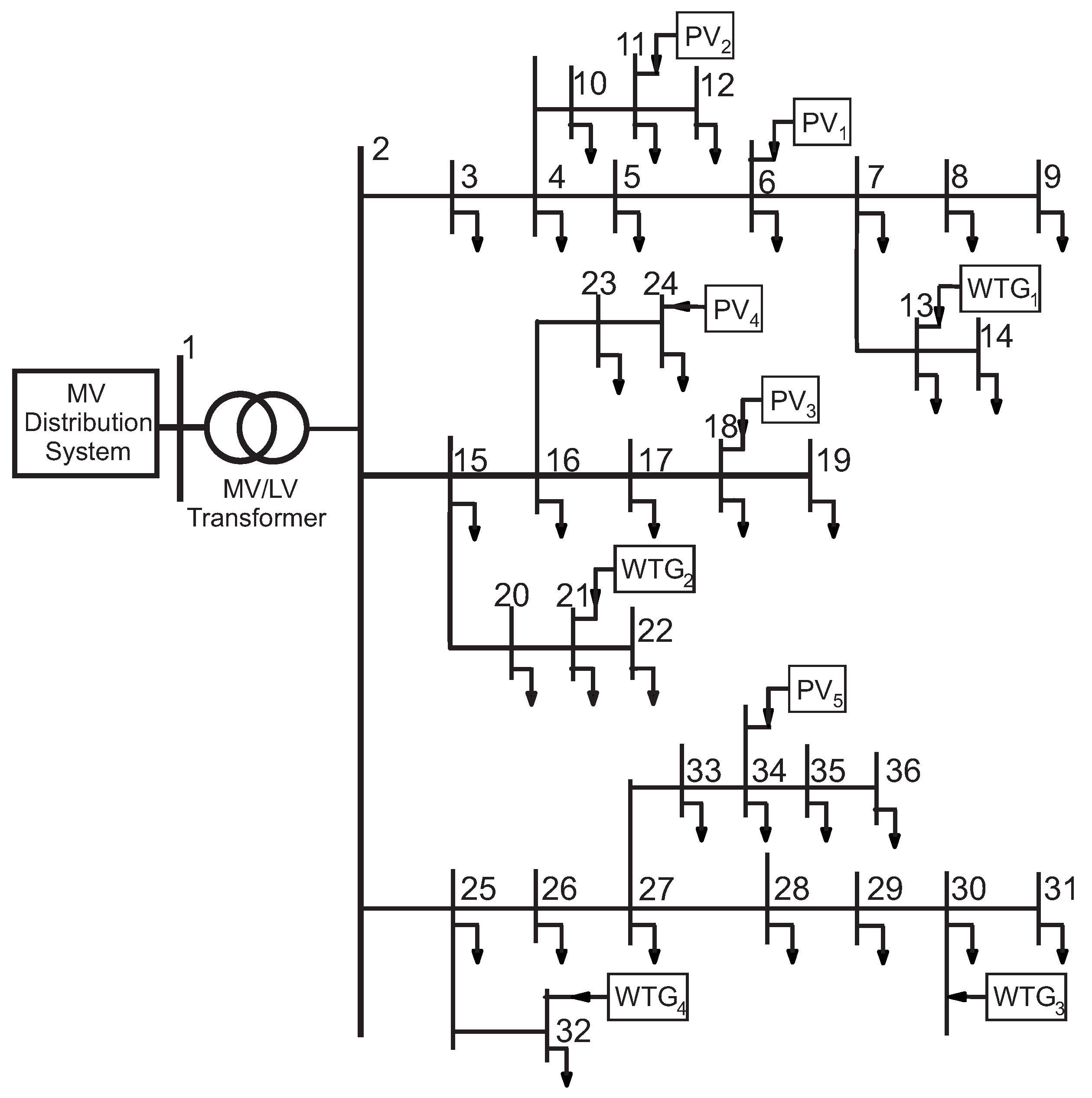
To assess the control performance achieved by the proposed method, the LV ADN depicted in Figure 2 whose parameters are taken from [47] is considered to be a test system. The penetration of the DERs is large: there are 9 nodes out of 34 total nodes equipped with a DER. Moreover, due to the limited extension of the network and the high R / X ratios of the distribution lines, the interaction among the control loops of any DER is strong.
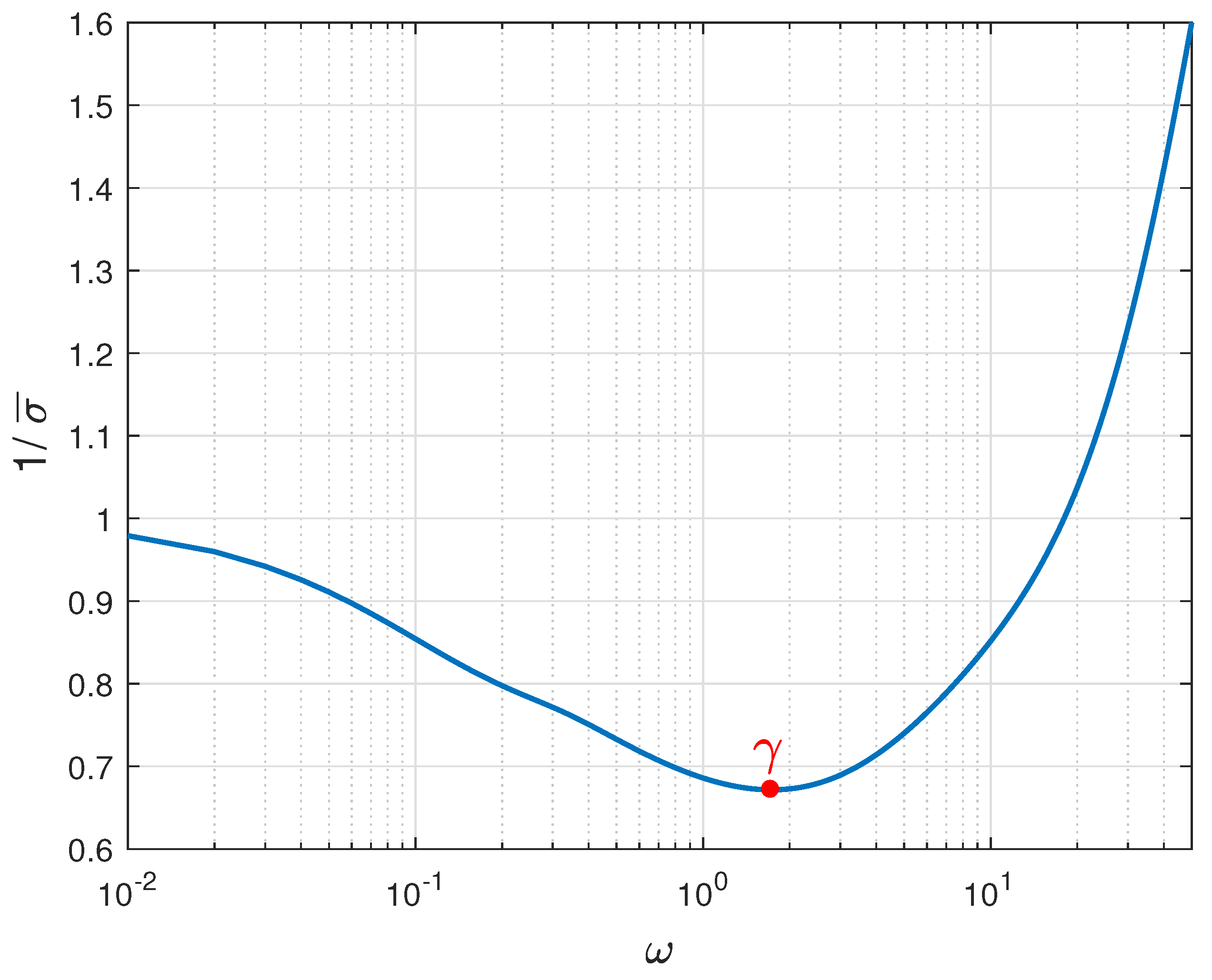
Firstly, with reference to the assumed operating condition, we have verified the fulfillment of condition (17). In particular we have calculated that the smallest eigenvalue is equal to 0.0714 . Subsequently, we have designed C ^ ( s ) according to (16) and numerically determined that k = 14.6 . Hence, we have set k I m = 1 and k I M = 10 so as to guarantee a smooth time response. Hence, problem (18) is solved by the sequential quadratic programming algorithm of the fmincon function available in the MATLAB library. It is obtained that k I = 3.585 . Hence, the robust stability has been investigated by drawing the frequency plot of the right-hand side of Equation (19) as shown in Figure 3. The minimum value of the curve is equal to the robust index γ , while the region below the curve represents the stability domain. In this case, it is obtained that γ = 0.6716 , a value similar to or greater than those of others techniques [48].
Furthermore, the fulfillment of condition (17) was evaluated considering different locational placements of all DERs within the ADN. In fact, different positions of DERs cause different matrices Γ P and Γ Q in (6) and consequently different matrices T . In details, Table 1 reports the value of the smallest eigenvalue of T diag { T j j 1 } for all the considered configurations. It is evident that condition (17) is always guaranteed. Eventually, it is worth underlining that a detailed numerical analysis has been performed considering many other possible numbers of DERs in the distribution network, and in all the cases, condition (17) has always been verified. In particular, in the extreme case in which all the 34 LV nodes are equipped by a DER, corresponding to a matrix T diag { T j j 1 } with dimension ( 68 × 68 ) , the value of its smallest eigenvalue results to be 0.0034. Then, the fulfillment of condition (17) is guaranteed even in the presence of an huge number of DERs for the considered ADN. From the developed analysis, we may conclude that the property of integral controllability can always be ensured with the proposed C ^ ( s ) in (16), regardless of the number of DERs.
To validate the effectiveness of the proposed design, five cases study are developed in the PSCAD-EMTDC environment [49]. In each of them, the operating condition of the ADN is different from the one used in the design. In details, the five cases are as follows:
Case 1: 
Connection and disconnection of a load;
Case 2: 
Variation in solar radiation;
Case 3: 
Variation in wind speed;
Case 4: 
Presence of inaccuracy in network line parameters;
Case 5: 
Disconnection of a DER.
Finally, the results of three additional simulations are presented in order to compare the performance achieved by the proposed method with the one obtained using the design procedure in [38]. In detail, they are as follows:
Case 6: 
Response to a step variation of v d e s of P V 1 ;
Case 7: 
As case 1;
Case 8: 
As case 5.

4.1. Case 1

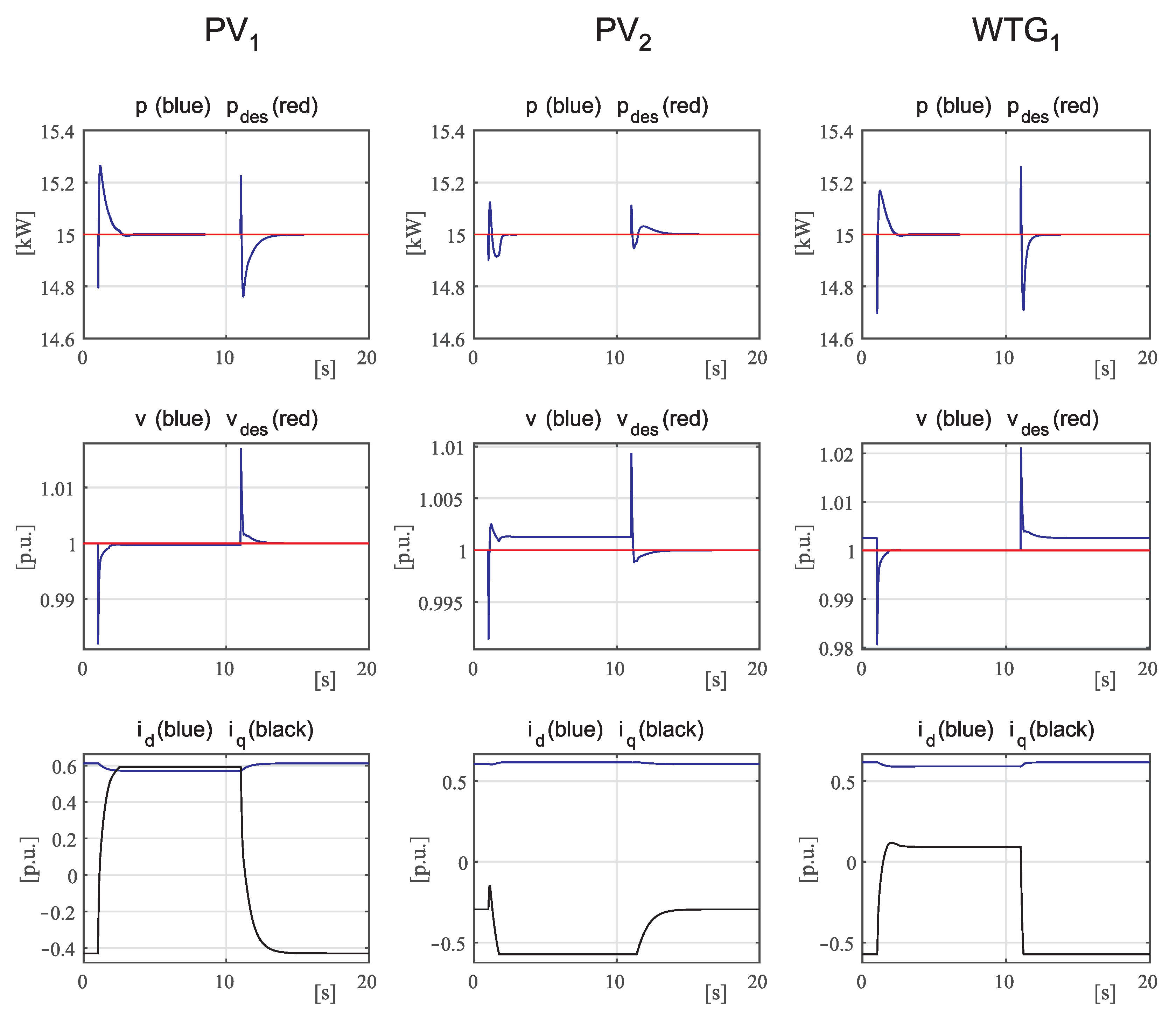
The first simulation is run to analyze the performance in response to a voltage disturbance caused by the sudden connection or disconnection of a load. The ADN operates with loads equal to 70% of their rated values and the voltage of the MV busbar equal to 1.0 p.u. Concerning the DERs, PVs are subject to 800 W / m 2 solar irradiance, whereas the WTGs to 10 m/s wind speed. The set points are equal, respectively, to 15 kW for all the active power control loops and to 1.0 p.u. for all the voltage control loops. Starting from such operating conditions, at node 8 of the first feeder, a 10 kW/5 kVAR load is suddenly connected at time instant 1 s and then disconnected at time instant 11 s. Since the larger voltage variations take place in the first feeder, the time evolution of the electrical quantities of interest for the three DERs connected to the first feeder are reported in Figure 4. In particular, the regulated variables, that are the DER active powers and voltage amplitudes at the PCC, are reported together with the corresponding set points; in addition, the control variables i d and i q are reported in the last row. From the analysis of Figure 4, it is apparent that stable smooth yet fast responses to the perturbations are guaranteed for both regulated variables. The steady-state error is zero except for the cases in which the current component i q is saturated to its bounds (see PV   1 and PV   2 when the additional load is connected). Finally, the control variables also present smooth variations without any oscillations, thus giving evidence of the ability of the proposed model to adequately account for the coupling among the two quantities.

4.2. Case 2

The second simulation analyzes the performance obtained in response to a variation in the solar radiation. Furthermore, the voltage amplitudes will be affected due to the significant impact of active power flows on the voltages in LV distribution feeders. The ADN operates with loads equal to 100% of their rated values and the voltage of the MV busbar equal to 1.025 p.u. Concerning the DERs, PVs are subject to 1000 W / m 2 solar irradiance, and the active power set points are set to 18 kW. The WTGs are subject to 10 m/s wind speed, and the active power set points are equal to 15 kW. All the voltage set points are set equal to 1.0 p.u. Starting from such an operating condition, the effect of passing cloud is simulated: at time instant equal to 1 s, the irradiance suddenly decrease to 200 W / m 2 and at time instant equal to 11 s is suddenly restored to 1000 W / m 2 . Since the impact is mainly on the PVs, the time evolution of the electrical quantities of interests for PV   3 , PV   4 and PV   5 , connected to the second and third feeder, are reported in Figure 5. In particular, the first row reports the plots of the injected active powers together with the solar irradiation, whereas the second row reports the plots of the other regulated variables that are the voltage amplitudes at the PCC, together with the unitary set points; in addition, the control variables i d and i q are reported in the last row. The analysis of Figure 5 confirms the same conclusions drawn for the previous first simulation, concerning the smooth yet fast responses to the perturbations that are guaranteed for both regulated and control variables. Due to the large variations in the injected active powers, the consequent voltage variations are large too and the current component i q is often saturated to its bounds. The consequence is the non-zero steady-state error on the voltage amplitude, but since the error is kept small, the contribution of DER to keeping the voltage amplitude near to the unitary value is quite evident anyway.

4.3. Case 3

The third simulation analyzes the performance in response to the variation in the wind speed. Furthermore, in this case, the voltage amplitudes will be affected due to the significant impact of active power flows on the voltages in LV distribution feeders. The ADN operates with loads equal to 50% of their rated values and the voltage of the MV busbar equal to 1.0 p.u. Concerning the DERs, PVs are subject to 500 W / m 2 solar irradiance and the active power set points are set to 10 kW. The WTGs are subject to a variable wind speed, changing between 5 and 10 m/s, and consequently to variable set points for the active power according to the WTG characteristics. The variations are supposed to be similar but not exactly the same for the four different WTGs. All of the voltage set points are set equal to 1.0 p.u. Since the impact is mainly on the WTGs, the time evolution of the electrical quantities of interest for WTG   2 , WTG   3 , and WTG   4 , connected to the second and third feeder, are reported in Figure 6. In particular, the first row reports the plots of the injected active powers together with the wind speed, whereas the second row reports the plots of the other regulated variables, which are the voltage amplitudes at the PCC, together with the unitary set points; in addition, the control variables i d and i q are reported in the last row. The analysis of Figure 6 confirms the same conclusions drawn for the previous simulations, concerning the smooth yet fast responses to the perturbations that are guaranteed for both regulated and control variables. In particular, the fast response of the active power to the wind speed variations is evident, as well as the ability to keep the voltage at the unitary value in spite of such perturbations, when the current component i q does not saturate (see WTG   2 when the wind speed is low and WTG   4 when the wind speed is high).

4.4. Case 4

The scope of the fourth simulation is to show the performance in the presence of line parameter inaccuracy of the ADN. The simulation replicates the same operating conditions and the same perturbations as the ones in Case 1, except for all the values of the line impedances of the ADN, which have been increased by 20%. Figure 7 reports the same quantities as the ones in Figure 4 for the DERs connected to the first feeder, where the load connection and disconnection takes place. From the comparison between the two figures, it is apparent that the performance of the proposed control is quite robust with respect to the uncertainties on the system parameters.

4.5. Case 5

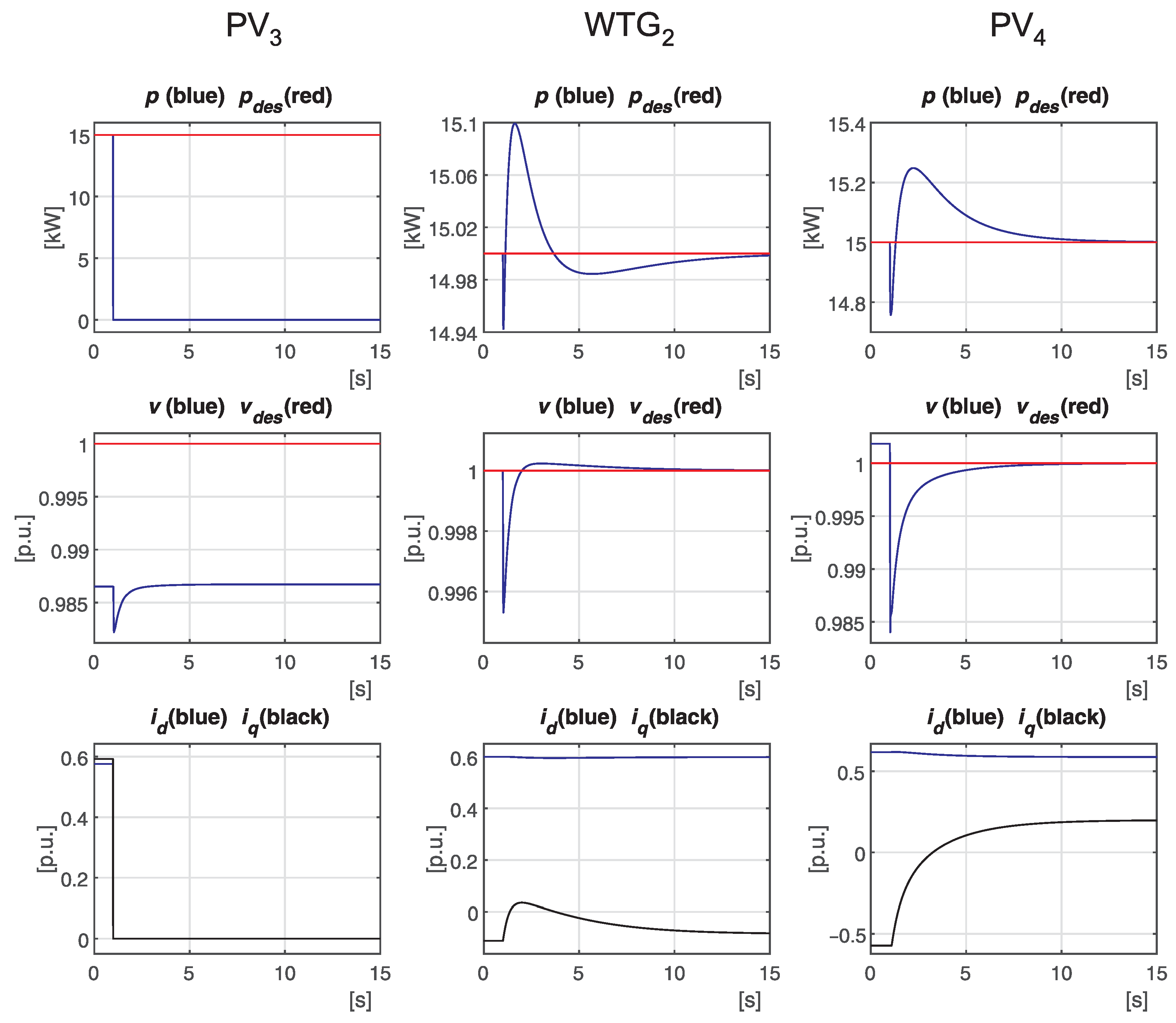
The fifth simulation aims at showing the results obtained when a DER is disconnected. In particular, at a time instant equal to 1 s, the PV   3 is disconnected. Figure 8 reports the time evolution of the active power, nodal voltage and current components for the DERs connected along the second feeder, including PV   3 that is disconnected. From the analysis of the figure, it is evident that the other two DERs promptly react to the perturbation related to the disconnection of PV   3 by restoring both the active power and the voltage at the desired values. The variation in the control variables, that is, the current components, is very smooth. In conclusion, the proposed control proves to be robust also with respect this perturbation.

4.6. Comparisons

The proposed technique has been compared with the method presented in [38] which uses the following criterion:
I A E = i = 1 0 | e i ( t ) | d t
In this paper, e i is either the active power error p i p d e s , i or the voltage error v i v d e s , i ; hence, we have two indices, namely I A E p and I A E v .

4.7. Case 6

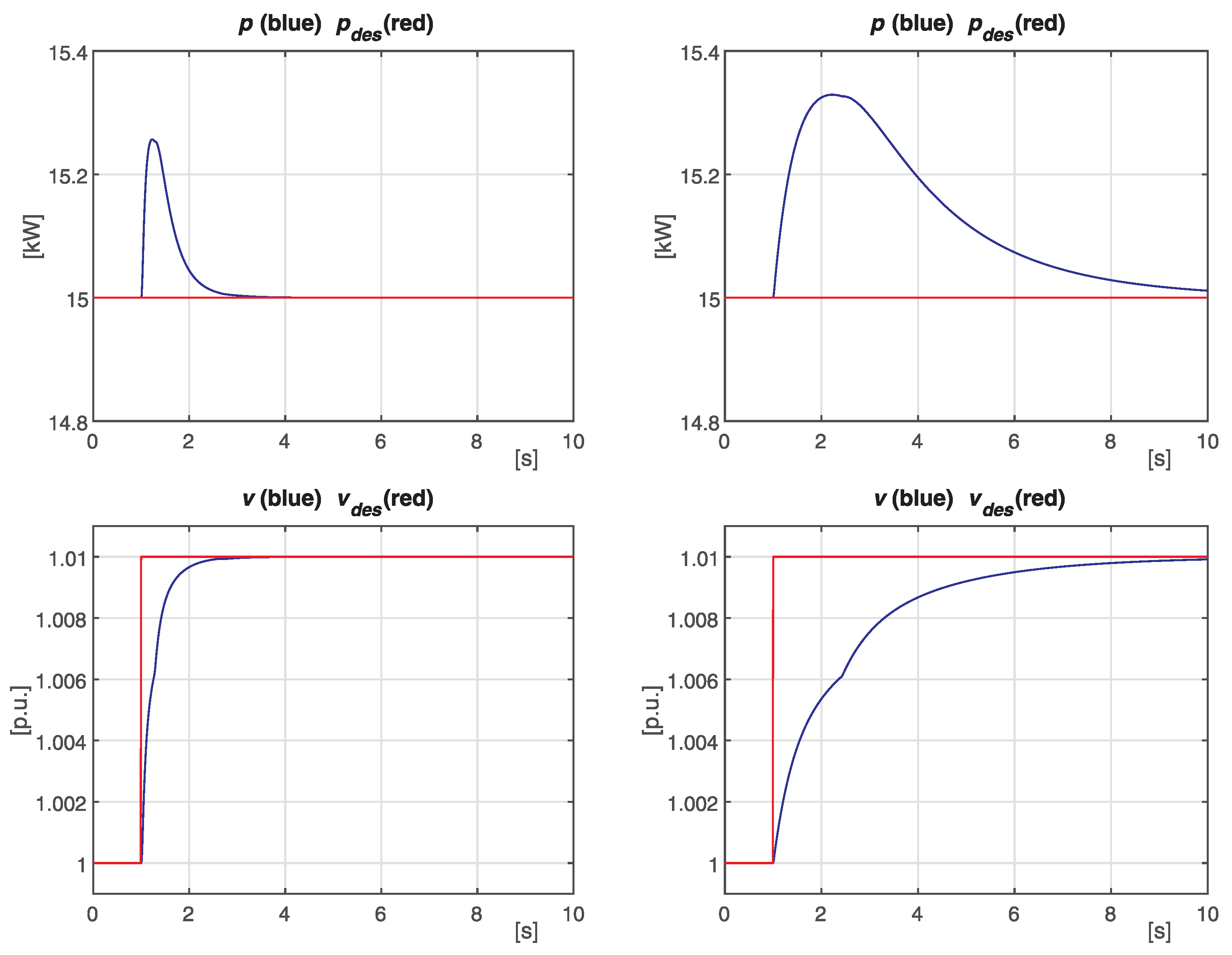
The first comparison is performed in terms of response to a step variation of the voltage set point. In details, v d e s of P V 1 is changed from 1.0 to 1.01 p.u. at a time instant equal to 1.0 s. Figure 9 reports the time evolution of the active power and voltage for P V 1 for both the proposed controllers and the controllers in [38]. It is apparent that a better response is obtained by the proposed controllers, which is confirmed by the resulting values of I A E p and I A E v reported in Table 2.
In the presence of changes in the operating conditions, for example, load insertion, the regulated signals v i and p i vary with respect to their steady-state values ( v d e s , i and p d e s , i ). Extending the use of the performance index to these cases, it can be stated that smaller values of I A E imply a shorter time needed to recover the equilibrium values and a better robust performance.

4.8. Case 7

Then, the second comparison refers to the sequence of load connection and disconnection as in the previous Case 1. In particular, in the case of the controllers in [38], Figure 10 reports the same quantities shown in Figure 4. From the comparison of the two figures, this case also gives evidence of the better performance guaranteed by the proposed design.

4.9. Case 8

The third comparison refers to the DER disconnection as in the previous Case 5. From the comparison between Figure 11 (for the controllers in [38]) and Figure 8, the superiority of the designed controllers is evident.
Finally, Table 3 compares the resulting values of I A E p and I A E v for both Case 1 and Case 5 and confirm the above remarks.

5. Conclusions

This paper has shown that a stable voltage regulation in ADNs with multiple DERs under different operating scenarios can be guaranteed by decentralized multi-loop controllers. The goal is attained by imposing the property of integral controllability to the open-loop matrix. According to the proposed technique, each DER is controlled by a two-inputs two-outputs matrix with fixed gains and a simple integral action. This simple structure allows us to express the design problem in terms of a single parameter. In the presence of uncertainty in the matrix plant, the free parameter is designed so as to maximize the degree of robust stability. The results of eight different numerical simulations have shown that the problem of guaranteeing a stable voltage regulation can successfully be addressed using the proposed method which has exhibited smaller values of the IAE compared with the ones given by the application of the internal model control technique with detuned factors.

Author Contributions

Conceptualization, G.F. and M.R.; Methodology, G.F. and M.R.; Software PSCAD 4.6 and Matlab R2023b, G.F. and M.R.; Validation, G.F. and M.R.; Formal analysis, G.F. and M.R.; Investigation, G.F. and M.R.; Resources, M.R.; Writing—original draft, G.F. and M.R.; Funding acquisition, M.R. All authors have read and agreed to the published version of the manuscript.

Funding

The research is financially supported by the Project “Ecosistema dell’innovazione-Rome Technopole” financed by EU in NextGenerationEU plan through MUR Decree n. 1051 23.06.2022-CUP H33C22000420001.

Data Availability Statement

Dataset available on request from the authors.

Conflicts of Interest

The authors declare no conflicts of interest. The funder had no role in the design of the study; in the collection, analyses, or interpretation of data; in the writing of the manuscript; or in the decision to publish the results.

References

  1. Tatar, S.M.; Aydin, E. Design and operation of renewable energy microgrids under uncertainty towards green deal and minimum carbon emissions. Sustain. Energy Grids Netw. 2024, 37, 101233. [Google Scholar] [CrossRef]
  2. Abdelkader, A.; Abdelkader, A.; Abdelkader, S.; Benidris, M. Voltage Stability Enhancement Using Local Measurements in Active Distribution Networks. In Proceedings of the 2023 North American Power Symposium (NAPS), Asheville, NC, USA, 15–17 October 2023; pp. 1–6. [Google Scholar]
  3. Constante, G.; Wang, J. Hierarchical Mechanism of Voltage Instability with Active Distribution Networks. In Proceedings of the 2018 Clemson University Power Systems Conference (PSC), Charleston, SC, USA, 4–7 September 2018; pp. 1–6. [Google Scholar]
  4. Ferreira, D.M.; Carvalho, P.M. Stability Analysis of Local Control Interactions in Active Distribution Networks. In Proceedings of the 2023 IEEE International Conference on Energy Technologies for Future Grids (ETFG), Wollongong, Australia, 3–6 December 2023; pp. 1–6. [Google Scholar]
  5. Hatziargyriou, N.; Milanović, J.; Rahmann, C.; Ajjarapu, V.; Cañizares, C.; Erlich, I.; Hill, D.; Hiskens, I.; Kamwa, I.; Pal, B.; et al. Stability definitions and characterization of dynamic behavior in systems with high penetration of power electronic interfaced technologies. In IEEE PES Technical Report PES-TR77; IEEE: Piscataway, NJ, USA, 2020. [Google Scholar]
  6. Kazeminejad, M.; Banejad, M.; Annakkage, U.; Hosseinzadeh, N. The effect of high penetration level of distributed generation sources on voltage stability analysis in unbalanced distribution systems considering load model. J. Oper. Autom. Power Eng. 2019, 7, 196–205. [Google Scholar]
  7. Lee, H.; Srivastava, A.K.; Krishnan, V.V.; Niddodi, S.; Bakken, D.E. Decentralized voltage stability monitoring and control with distributed computing coordination. IEEE Syst. J. 2021, 16, 2251–2260. [Google Scholar] [CrossRef]
  8. Venegas, F.G.; Meunier, S.; Protopapadaki, C.; Perez, Y.; Saelens, D.; Petit, M. Impact of distributed energy resources and electric vehicle smart charging on low voltage grid stability. In Proceedings of the CIRED 2021—The 26th International Conference and Exhibition on Electricity Distribution, Online Conference, 20–23 September 2021. [Google Scholar]
  9. Rahman, S.; Saha, S.; Islam, S.N.; Arif, M.T.; Mosadeghy, M.; Haque, M.; Oo, A.M. Analysis of power grid voltage stability with high penetration of solar PV systems. IEEE Trans. Ind. Appl. 2021, 57, 2245–2257. [Google Scholar] [CrossRef]
  10. Ranamuka, D.; Agalgaonkar, A.; Muttaqu, K. Online Voltage Control in Distribution Systems With Multiple Voltage Regulating Devices. IEEE Trans. Sustain. Energy 2014, 5, 617–628. [Google Scholar] [CrossRef]
  11. Rizvi, S.M.H.; Srivastava, A.K. Integrated T&D voltage stability assessment considering impact of DERs and distribution network topology. IEEE Access 2023, 11, 14702–14714. [Google Scholar]
  12. Lundberg, M.; Samuelsson, O.; Hillberg, E. Local voltage control in distribution networks using PI control of active and reactive power. Electr. Power Syst. Res. 2022, 212, 108475. [Google Scholar] [CrossRef]
  13. Fusco, G.; Russo, M. A Decentralized Approach for Voltage Control by Multiple Distributed Energy Resources. IEEE Trans. Smart Grid 2021, 12, 3115–3127. [Google Scholar] [CrossRef]
  14. Rafiee, A.; Batmani, Y.; Bevrani, H.; Kato, T. Robust mimo controller design for vsc-based microgrids: Sequential loop closing concept and quantitative feedback theory. IEEE Trans. Smart Grid 2021, 13, 129–138. [Google Scholar] [CrossRef]
  15. Ashabani, M.; Yasser, A.R.M.; Mirsalim, M.; Aghashabani, M. Multivariable droop control of synchronous current converters in weak grids/microgrids with decoupled dq-axes currents. IEEE Trans. Smart Grid 2015, 6, 1610–1620. [Google Scholar] [CrossRef]
  16. Zhao, M.; Yuan, X.; Hu, J.; Yan, Y. Voltage dynamics of current control time-scale in a VSC-connected weak grid. IEEE Trans. Power Syst. 2015, 31, 2925–2937. [Google Scholar] [CrossRef]
  17. Sun, X.; Qiu, J.; Zhao, J. Optimal local volt/var control for photovoltaic inverters in active distribution networks. IEEE Trans. Power Syst. 2021, 36, 5756–5766. [Google Scholar] [CrossRef]
  18. Merritt, N.R.; Chakraborty, C.; Bajpai, P. New voltage control strategies for VSC-based DG units in an unbalanced microgrid. IEEE Trans. Sustain. Energy 2017, 8, 1127–1139. [Google Scholar] [CrossRef]
  19. Antoniadu-Plytaria, K.; Kouveliotis-Lysikatos, I.; Georgilakis, P.; Hatziargyriou, N. Distributed and Decentralized Voltage Control of smart Distribution Networks: Models, Methods, and Future Research. IEEE Trans. Smart Grid 2017, 8, 2999–3008. [Google Scholar] [CrossRef]
  20. Patari, N.; Srivastava, A.K.; Qu, G.; Li, N. Distributed voltage control for three-phase unbalanced distribution systems with ders and practical constraints. IEEE Trans. Ind. Appl. 2021, 57, 6622–6633. [Google Scholar] [CrossRef]
  21. Li, P.; Zhang, C.; Wu, Z.; Xu, Y.; Hu, M.; Dong, Z. Distributed adaptive robust voltage/var control with network partition in active distribution networks. IEEE Trans. Smart Grid 2019, 11, 2245–2256. [Google Scholar] [CrossRef]
  22. Reno, M.J.; Quiroz, J.E.; Lavrova, O.; Byrne, R.H. Evaluation of communication requirements for voltage regulation control with advanced inverters. In Proceedings of the 2016 North American Power Symposium (NAPS), Denver, CO, USA, 18–20 September 2016; pp. 1–6. [Google Scholar]
  23. Wu, X.; Deng, S.; Yuan, W.; Mei, S. A Robust Distributed Secondary Control of Microgrids Considering Communication Failures. In Proceedings of the 2022 4th International Conference on Power and Energy Technology (ICPET), Beijing, China, 28–31 July 2022; pp. 395–400. [Google Scholar]
  24. Kundur, P. Power System Stability and Control; McGraw-Hill, Inc.: New York, NY, USA, 1994. [Google Scholar]
  25. Abdel-Akher, M. Voltage stability analysis of unbalanced distribution systems using backward/forward sweep load-flow analysis method with secant predictor. IET Gener. Transm. Distrib. 2013, 7, 309–317. [Google Scholar] [CrossRef]
  26. Li, Q.; Zhang, Y.; Ji, T.; Lin, X.; Cai, Z. Volt/var control for power grids with connections of large-scale wind farms: A review. IEEE Access 2018, 6, 26675–26692. [Google Scholar] [CrossRef]
  27. Liu, W.; Gu, W.; Xu, Y.; Wang, Y.; Zhang, K. General distributed secondary control for multi-microgrids with both PQ-controlled and droop-controlled distributed generators. IET Gener. Transm. Distrib. 2017, 11, 707–718. [Google Scholar] [CrossRef]
  28. Simpson-Porco, J.W.; Dörfler, F.; Bullo, F. Voltage stabilization in microgrids via quadratic droop control. IEEE Trans. Autom. Control 2016, 62, 1239–1253. [Google Scholar] [CrossRef]
  29. Schiffer, J.; Ortega, R.; Astolfi, A.; Raisch, J.; Sezi, T. Conditions for stability of droop-controlled inverter-based microgrids. Automatica 2014, 50, 2457–2469. [Google Scholar] [CrossRef]
  30. Eggli, A.; Karagiannopoulos, S.; Bolognani, S.; Hug, G. Stability analysis and design of local control schemes in active distribution grids. IEEE Trans. Power Syst. 2020, 36, 1900–1909. [Google Scholar] [CrossRef]
  31. Saidi, A.S. Impact of grid-tied photovoltaic systems on voltage stability of tunisian distribution networks using dynamic reactive power control. Ain Shams Eng. J. 2022, 13, 101537. [Google Scholar] [CrossRef]
  32. Zevallos, O.C.; Da Silva, J.B.; Mancilla-David, F.; Neves, F.A.; Neto, R.C.; Prada, R.B. Control of photovoltaic inverters for transient and voltage stability enhancement. IEEE Access 2021, 9, 44363–44373. [Google Scholar] [CrossRef]
  33. Shi, Y.; Baran, M. A gradient based decentralized volt/var optimization scheme for distribution systems with high DER penetration. In Proceedings of the 2019 IEEE PES GTD Grand International Conference and Exposition Asia (GTD Asia), Bangkok, Thailand, 19–23 March 2019; pp. 649–654. [Google Scholar]
  34. Panjwani, S.; Nikolaou, M. Ensuring integral controllability for robust multivariable control. Comput. Chem. Eng. 2016, 92, 172–179. [Google Scholar] [CrossRef]
  35. Grosdidier, P.; Morari, M.; Holt, B. Closed-Loop Properties from the Steady-State Information. Ind. Eng. Chem. Fundam. 1985, 24, 221–235. [Google Scholar] [CrossRef]
  36. Morari, M. Robust Stability of Systems with Integral Control. IEEE Trans. Autom. Control 1985, 30, 574–577. [Google Scholar] [CrossRef]
  37. Su, S.W.; Tuan, H.; Chen, W.; Nguyen, H.; Celler, B.G. Conditions for simultaneous decentralized integral controllability. In Proceedings of the 2015 5th Australian Control Conference (AUCC), Gold Coast, QLD, Australia, 5–6 November 2015; pp. 144–147. [Google Scholar]
  38. Aldhandi, S.; Detroja, K.P. Controller design for highly interacting multivariable systems. In Proceedings of the 2022 Eighth Indian Control Conference (ICC), Chennai, India, 14–16 December 2022; pp. 127–132. [Google Scholar]
  39. Kammer, C.; Karimi, A. Decentralized and Distributed Transient Control for Microgrids. IEEE Trans. Control Syst. Technol. 2019, 27, 311–322. [Google Scholar] [CrossRef]
  40. Schauder, C.; Mehta, H. Vector analysis and control of advanced static VAr compensators. IEE Proc. C-Gener. Transm. Distrib. 1993, 140, 299–306. [Google Scholar] [CrossRef]
  41. Zhang, Z.; Ochoa, L.; Valverde, G. A Novel Voltage Sensitivity Approach for the Decentralized Control of DG Plants. IEEE Trans. Power Syst. 2018, 3, 1566–1576. [Google Scholar] [CrossRef]
  42. Fusco, G.; Russo, M. Robust MIMO Design of Decentralized Voltage Controllers of PV Systems in Distribution Networks. IEEE Trans. Ind. Electron. 2017, 64, 4610–4620. [Google Scholar] [CrossRef]
  43. Di Fazio, A.R.; Russo, M.; Valeri, S.; De Santis, M. Linear method for steady-state analysis of radial distribution systems. Int. J. Electr. Power Energy Syst. 2018, 99, 744–755. [Google Scholar] [CrossRef]
  44. Kashem, M.; Ledwich, G. Multiple distributed Generators for Distribution Feeder Voltage Support. IEEE Trans. Energy Convers. 2005, 20, 676–684. [Google Scholar] [CrossRef]
  45. Putratama, M.A.; Rigo-Mariani, R.; Debusschere, V.; Bésanger, Y. Mitigation of grid parameter uncertainties for the steady-state operation of a model-based voltage controller in distribution systems. Electr. Power Syst. Res. 2023, 218, 109221. [Google Scholar] [CrossRef]
  46. Skogestad, S.; Postlethwaite, I. Multivariable Feedback Control: Analysis and Design; John Wiley & Sons: Hoboken, NJ, USA, 2005. [Google Scholar]
  47. Fusco, G.; Russo, M.; Casolino, G.M. Voltage and active power local PI control of distributed energy resources based on the effective transfer function method. Int. J. Electr. Power Energy Syst. 2023, 152, 109264. [Google Scholar] [CrossRef]
  48. Jeng, J.C.; Lee, M.W. Multi-loop PID controllers design with reduced loop interactions based on a frequency-domain direct synthesis method. J. Frankl. Inst. 2023, 360, 2476–2506. [Google Scholar] [CrossRef]
  49. Centre, M.H.R. PSCAD User’s Guide; Manitoba Hydro International Ltd.: Winnipeg, MB, Canada, 2018. [Google Scholar]
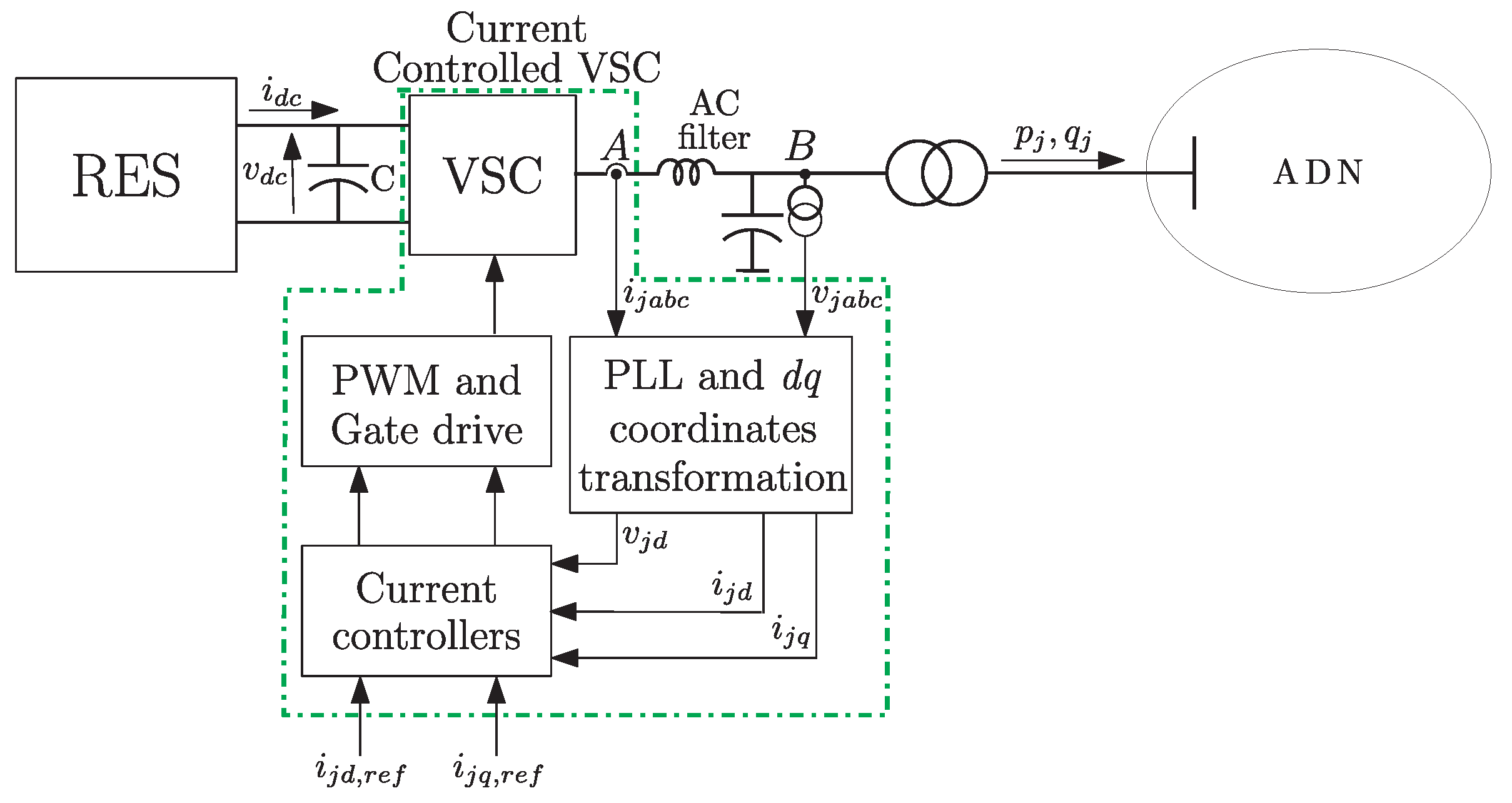
Figure 1. Functional block scheme of the current-controlled VSC and electrical circuit connecting the DER   j to the ADN.
Energies 17 02455 g001
Figure 2. LV active distribution network under study [47].
Energies 17 02455 g002
Figure 3. Robust stability bounds of the closed-loop system of the ADN under study.
Energies 17 02455 g003
Figure 4. Case 1: Time evolution of the main quantities of DERs of the first feeder in response to a sequence of connection–disconnection of a load.
Energies 17 02455 g004
Figure 5. Case 2: Time evolution of the main quantities of the PVs of the second and third feeder in response to a variation in the solar radiation.
Energies 17 02455 g005
Figure 6. Case 3: Time evolution of the main quantities of the WTGs of the second and third feeder in response to a variation in the wind speed.
Energies 17 02455 g006
Figure 7. Case 4: Time evolution of the main quantities of the DERs of the first feeder in presence of line parameter inaccuracy.
Energies 17 02455 g007
Figure 8. Case 5: Time evolution of the main quantities of the DERs of the second feeder when a DER is disconnected.
Energies 17 02455 g008
Figure 9. Case 6: Comparison of time evolution of active power (top) and voltage (bottom) for the PV   1 in response to a step variation in the voltage set point: proposed controllers (left) vs. controllers in [38] (right).
Energies 17 02455 g009
Figure 10. Case 7: Time evolution of the main quantities of DERs of the first feeder obtained by the controllers in [38] in response to a sequence of connection–disconnection of a load.
Energies 17 02455 g010
Figure 11. Case 8: Time evolution of the main quantities of the DERs of the second feeder obtained by the controllers in [38] in response to the DER disconnection.
Energies 17 02455 g011
Table 1. Smallest eigenvalue for different DERs configurations.
Configuration (Number of DERS for Each of the 3 Feeders)
1-1-71-2-62-2-52-3-43-1-53-3-34-1-46-2-1
λ m i n T diag { T j j 1 } 0.01150.02850.05440.06000.02690.07140.07240.0464
Table 2. Values of I A E p and I A E v for the proposed controllers and controllers in [38]: Case 6.
IAE p IAE v
Proposed controllers0.1700.0028
Controllers in [38]1.1730.0146
Table 3. Values of I A E p and I A E v for the proposed controllers and controllers in [38]: Case 7 and Case 8.
Case 7Case 8
IAE p IAE v IAE p IAE v
Proposed controllers0.6410.05400.1510.0038
Controllers in [38]4.1700.10211.1120.0189
Disclaimer/Publisher’s Note: The statements, opinions and data contained in all publications are solely those of the individual author(s) and contributor(s) and not of MDPI and/or the editor(s). MDPI and/or the editor(s) disclaim responsibility for any injury to people or property resulting from any ideas, methods, instructions or products referred to in the content.