
Modeling and Control of Ejector-Based Hydrogen Circulation System for Proton Exchange Membrane Fuel Cell Systems


Abstract
:1. Introduction
- (1)
- A semi-empirical model is proposed to predict the ejector’s performance accurately.
- (2)
- The developed fuzzy logic controller regulates the anode pressure and hydrogen supply.
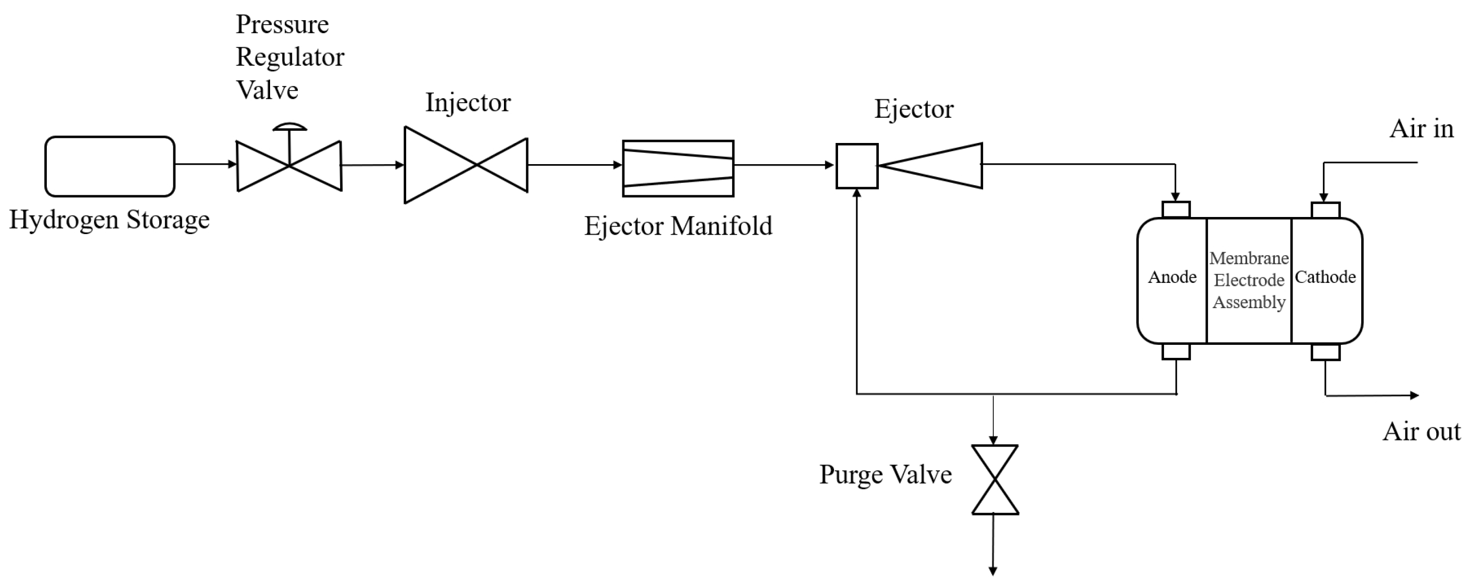
2. Materials and Methods
- The hydrogen source outlet pressure is always stable.
- There is no pressure drop at the piping connections.
- The variation in space in the gas supply manifold is ignored.
- The ideal gas law applies to all volumes.
2.1. Injector
2.2. Manifold
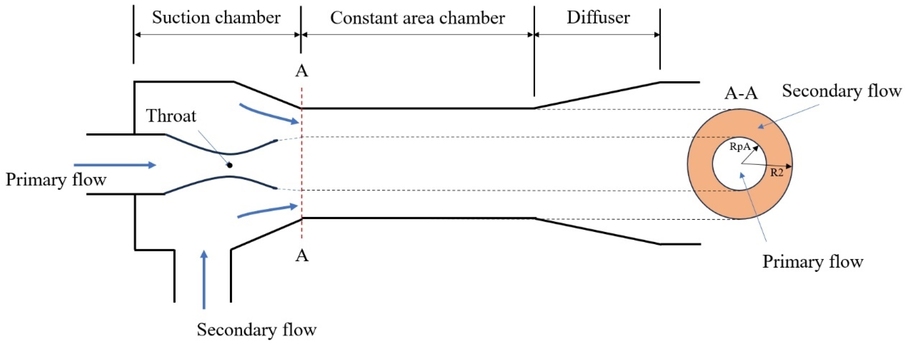
2.3. Ejector
2.4. Anode Channel Modeling
2.5. Purge Valve
2.6. Model Validation
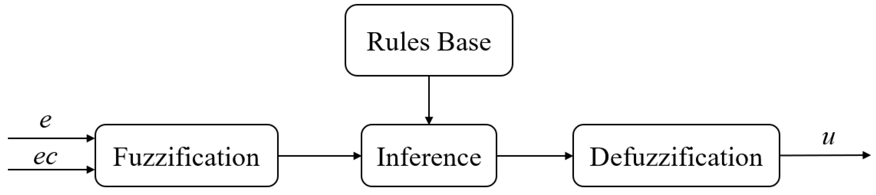
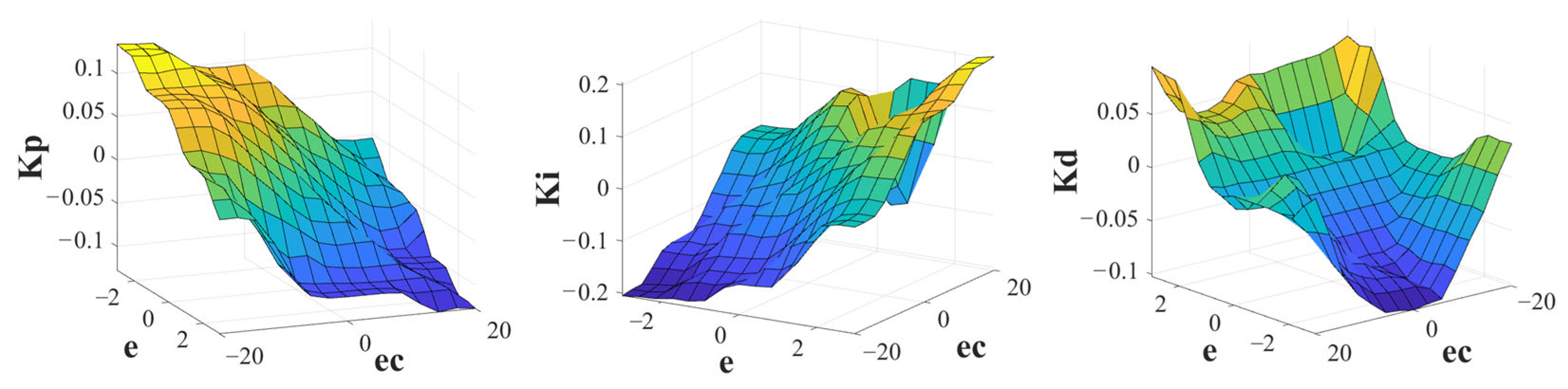
2.7. Fuzzy Logic Control
2.7.1. Fuzzification
2.7.2. Inference Rules
2.7.3. Inference Engine
2.7.4. Defuzzification
3. Results
3.1. Performance under Step Case
3.2. Performance under Dynamic Case
4. Discussion
5. Conclusions
- (1)
- The proposed ejector modeling method effectively simulates and predicts the ejector performance under various conditions. The imaginary pressure difference at the A-A section supports the novel modeling and enables accurate control-oriented modeling.
- (2)
- The fuzzy PID controller we developed ameliorates the anode pressure error under transient patterns. The maximum pressure difference is bounded by 5% at transient operating patterns.
Author Contributions
Funding
Data Availability Statement
Acknowledgments
Conflicts of Interest
References
- Ding, H.; Dong, Y.; Zhang, Y.; Yang, Y.; Wen, C. Energy efficiency assessment of hydrogen recirculation ejectors for proton exchange membrane fuel cell (PEMFC) system. Appl. Energy 2023, 346, 121357. [Google Scholar] [CrossRef]
- He, Y.; Zhou, Y.; Yuan, J.; Liu, Z.; Wang, Z.; Zhang, G. Transformation towards a carbon-neutral residential community with hydrogen economy and advanced energy management strategies. Energy Convers. Manag. 2021, 249, 114834. [Google Scholar] [CrossRef]
- Daud, W.R.W.; Rosli, R.E.; Majlan, E.H.; Hamid, S.A.A.; Mohamed, R.; Husaini, T. PEM fuel cell system control: A review. Renew. Energy 2017, 113, 620–638. [Google Scholar] [CrossRef]
- Gao, X.; Chen, J.; Xu, R.; Zhen, Z.; Zeng, X.; Chen, X.; Cui, L. Research progress and prospect of the materials of bipolar plates for proton exchange membrane fuel cells (PEMFCs). Int. J. Hydrogen Energy 2023, 50, 711–743. [Google Scholar] [CrossRef]
- Lee, H.Y.; Su, H.C.; Chen, Y.S. A gas management strategy for anode recirculation in a proton exchange membrane fuel cell. Int. J. Hydrogen Energy 2018, 43, 3803–3808. [Google Scholar] [CrossRef]
- Song, Y.; Wang, L.; Jia, L.; Wang, X. Optimization and performance investigation of confocal twin-nozzle ejector for PEMFC hydrogen supply and recirculation system under actual variable operating conditions. Int. J. Hydrogen Energy 2023, 50, 1450–1464. [Google Scholar] [CrossRef]
- Aminudin, M.A.; Kamarudin, S.K.; Lim, B.H.; Majilan, E.H.; Masdar, M.S.; Shaari, N. An overview: Current progress on hydrogen fuel cell vehicles. Int. J. Hydrogen Energy 2023, 48, 4371–4388. [Google Scholar] [CrossRef]
- Huang, P.H.; Kuo, J.K.; Wu, C.B. Design and evaluation of dual passive hydrogen recovery subsystem for 10 kW PEMFC. Int. J. Hydrogen Energy 2023, 54, 483–490. [Google Scholar] [CrossRef]
- Wang, X.; Zheng, J.; Hao, Z.; Di, Y.; Miao, X. Study on the effect of pulsed gas flow on the entrainment performance of hydrogen ejector. Int. J. Hydrogen Energy 2024, 67, 599–607. [Google Scholar] [CrossRef]
- Yuan, H.; Dai, H.; Wu, W.; Xie, J.; Shen, J.; Wei, X. A fuzzy logic PI control with feedforward compensation for hydrogen pressure in vehicular fuel cell system. Int. J. Hydrogen Energy 2021, 46, 5714–5728. [Google Scholar] [CrossRef]
- Zhu, Y.; Cai, W.; Wen, C.; Li, Y. Shock circle model for ejector performance evaluation. Energy Convers. Manag. 2007, 48, 2533–2541. [Google Scholar] [CrossRef]
- Dadvar, M.; Afshari, E. Analysis of design parameters in anodic recirculation system based on ejector technology for PEM fuel cells: A new approach in designing. Int. J. Hydrogen Energy 2014, 39, 12061–12073. [Google Scholar] [CrossRef]
- Wang, X.; Xu, S.; Xing, C. Numerical and experimental investigation on an ejector designed for an 80 kW polymer electrolyte membrane fuel cell stack. J. Power Sources 2019, 415, 25–32. [Google Scholar] [CrossRef]
- Huang, B.J.; Chang, J.M.; Wang, C.P.; Petrenko, V.A. A 1-D analysis of ejector performance. Int. J. Refrig. 1999, 22, 354–364. [Google Scholar] [CrossRef]
- Nikiforow, K.; Koski, P.; Karimäki, H.; Ihonen, J.; Alopaeus, V. Designing a hydrogen gas ejector for 5 kW stationary PEMFC system–CFD-modeling and experimental validation. Int. J. Hydrogen Energy 2016, 41, 14952–14970. [Google Scholar] [CrossRef]
- Chen, L.; Xu, K.; Yang, Z.; Yan, Z.; Zhai, C.; Dong, Z. Optimal design of a novel nested-nozzle ejector for PEMFC’s hydrogen supply and recirculation system. Int. J. Hydrogen Energy 2023, 48, 27330–27343. [Google Scholar] [CrossRef]
- Han, J.; Zhao, B.; Pang, Z.; Feng, J.; Peng, X. Transient characteristics investigation of the integrated ejector-driven hydrogen recirculation by multi-component CFD simulation. Int. J. Hydrogen Energy 2022, 47, 29053–29068. [Google Scholar] [CrossRef]
- He, J.; Choe, S.Y.; Hong, C.O. Modeling and controls of a fuel delivery system with dual recirculation lines for a PEM fuel cell system. In Proceedings of the International Conference on Fuel Cell Science, Engineering and Technology, Denver, CO, USA, 16–18 June 2008; Volume 43181, pp. 661–673. [Google Scholar]
- He, J.; Choe, S.Y. Modeling and Control of a Hybrid Fuel Delivery System Based on a Two-Phase Anodic Model of a PEM Fuel Cell. In Proceedings of the International Conference on Fuel Cell Science, Engineering and Technology, Brooklyn, NY, USA, 14–16 June 2010; Volume 44045, pp. 771–781. [Google Scholar]
- Wang, F.C.; Ko, C.C. Multivariable robust PID control for a PEMFC system. Int. J. Hydrogen Energy 2010, 35, 10437–10445. [Google Scholar] [CrossRef]
- Xue, H.; Zhang, H.; Sun, W.; Yao, A.; Jia, L. An optimized Fuzzy PI control method utilizing an improved QPSO for the hydrogen supply of PEMFC. In Proceedings of the 2023 IEEE 18th Conference on Industrial Electronics and Applications (ICIEA), Ningbo, China, 18–22 August 2023; pp. 603–608. [Google Scholar]
- Wang, Y.; Zhang, H.; He, S.; Wang, W.; Gao, M.; Moiseevna, K.E.; Anatolievna, V.V. Dynamic analysis and control optimization of hydrogen supply for the proton exchange membrane fuel cell and metal hydride coupling system with a hydrogen buffer tank. Energy Convers. Manag. 2023, 291, 117339. [Google Scholar] [CrossRef]
- Li, C.; Li, X.; Jiang, W. Model-based control strategy research for the hydrogen system of fuel cell. IFAC-PapersOnLine 2021, 54, 67–71. [Google Scholar] [CrossRef]
- Huang, Y.; Jiang, P.; Zhu, Y. Quasi-two-dimensional ejector model for anode gas recirculation fuel cell systems. Energy Convers. Manag. 2022, 262, 115674. [Google Scholar] [CrossRef]
- Shao, Y.; Xu, L.; Fang, C.; Li, J.; Xu, L.; Hu, Z.; Shi, L.; Ouyang, M. Adoptive Control of Injector for Polymer Electrolyte Membrane Fuel Cell Hydrogen Feeding System. In Proceedings of the 2021 IEEE 4th International Electrical and Energy Conference (CIEEC), Wuhan, China, 28–30 May 2021; pp. 1–6. [Google Scholar]
- Pei, P.; Ren, P.; Li, Y.; Wu, Z.; Chen, D.; Huang, S.; Jia, X. Numerical studies on wide-operating-range ejector based on anodic pressure drop characteristics in proton exchange membrane fuel cell system. Appl. Energy 2019, 235, 729–738. [Google Scholar] [CrossRef]
- Kuo, J.K.; Thamma, U.; Wongcharoen, A.; Chang, Y.K. Optimized fuzzy proportional integral controller for improving output power stability of active hydrogen recovery 10-kW PEM fuel cell system. Int. J. Hydrogen Energy 2023, 50, 1080–1093. [Google Scholar] [CrossRef]
- Baroud, Z.; Benmiloud, M.; Benalia, A.; Ocampo-Martinez, C. Novel hybrid fuzzy-PID control scheme for air supply in PEM fuel-cell-based systems. Int. J. Hydrogen Energy 2017, 42, 10435–10447. [Google Scholar] [CrossRef]
- Yang, F.; Li, Y.; Chen, D.; Hu, S.; Xu, X. Evaluation method of oxygen excess ratio control under typical control laws for proton exchange membrane fuel cells. Int. J. Hydrogen Energy 2023, 48, 28516–28527. [Google Scholar] [CrossRef]
- Benchouia, N.E.; Derghal, A.; Mahmah, B.; Madi, B.; Khochemane, L.; Aoul, E.H. An adaptive fuzzy logic controller (AFLC) for PEMFC fuel cell. Int. J. Hydrogen Energy 2015, 40, 13806–13819. [Google Scholar] [CrossRef]


| Parameters | Symbols | Value |
|---|---|---|
| Injector cross-sectional area | Ainj [25] | 3.85 × 10⁻⁵ m2 |
| Pressure regulator valve pressure | Ptank | 2 × 10⁶ Pa |
| Non-uniform flow coefficient | Cd,inj [25] | 0.42 |
| Hydrogen cylinder temperature | Ttank | 298.15 K |
| Ideal gas constant | R | 8.314 J/(mol·K) |
| Hydrogen’s pressure-specific heat capacity | Cp_H | 14.05 J/(kg·K) |
| Hydrogen’s volume-specific heat capacity | Cv_H | 9.934 J/(kg·K) |
| Area of the ejector’s throat | Athroat [13] | 2.659 × 10⁻⁶ m2 |
| Diameter of the ejector’s throat | Dthroat [13] | 1.84 × 10⁻³ m |
| Supply manifold volume | Vsm [19] | 4 × 10⁻³ m3 |
| Isentropic flow coefficient | [12] | 0.95 |
| Diameter of constant area chamber | D2 [13] | 5.9 × 10⁻³ m |
| Anode volume of the stack | Van [19] | 5.3 × 10⁻³ m3 |
| Number of cells | Ncell | 1200 |
| Parameters | Variables | Fuzzy Definition Domain |
|---|---|---|
| Pressure difference | e(t) | (−3, 3) |
| Change rate of pressure difference | ec(t) | (−20, 20) |
| Adaptive proportional coefficient | ΔKp | (−0.05, 0.05) |
| Adaptive integral coefficient | ΔKi | (−0.1, 0.1) |
| Adaptive differential coefficient | ΔKd | (−0.01, 0.01) |
| ΔKp | ec | |||||||
|---|---|---|---|---|---|---|---|---|
| e | NB | NM | NS | ZO | PS | PM | PB | |
| NB | PB | PB | PM | PM | PS | ZO | ZO | |
| NM | PB | PB | PM | PS | PS | ZO | NS | |
| NS | PM | PM | PM | PS | ZO | NS | NS | |
| ZO | PM | PM | PS | ZO | NS | NM | NM | |
| PS | PS | PS | ZO | NS | NS | NM | NB | |
| PM | PS | ZO | NS | NM | NM | NM | NB | |
| PB | ZO | ZO | NM | NM | NM | NB | NB | |
| ΔKi | ec | |||||||
|---|---|---|---|---|---|---|---|---|
| e | NB | NM | NS | ZO | PS | PM | PB | |
| NB | NB | NB | NM | NM | NS | ZO | ZO | |
| NM | NB | NB | NM | NS | NS | ZO | ZO | |
| NS | NB | NM | NS | NS | ZO | PS | PS | |
| ZO | NM | NM | NS | ZO | PS | PM | PM | |
| PS | NM | NS | ZO | PS | PS | PM | PB | |
| PM | ZO | ZO | PS | PS | PM | PB | PB | |
| PB | ZO | ZO | PS | PM | PM | PB | PB | |
| ΔKd | ec | |||||||
|---|---|---|---|---|---|---|---|---|
| e | NB | NM | NS | ZO | PS | PM | PB | |
| NB | PS | NS | NB | NB | NB | NM | PS | |
| NM | PB | NS | NB | NM | NM | NS | ZO | |
| NS | ZO | NS | NM | NM | NS | NS | ZO | |
| ZO | ZO | NS | NS | NS | NS | NS | ZO | |
| PS | ZO | ZO | ZO | ZO | ZO | ZO | ZO | |
| PM | PB | PS | PS | PS | PS | PS | PB | |
| PB | PB | PM | PM | PM | PS | PS | PB | |
Disclaimer/Publisher’s Note: The statements, opinions and data contained in all publications are solely those of the individual author(s) and contributor(s) and not of MDPI and/or the editor(s). MDPI and/or the editor(s) disclaim responsibility for any injury to people or property resulting from any ideas, methods, instructions or products referred to in the content. |
© 2024 by the authors. Licensee MDPI, Basel, Switzerland. This article is an open access article distributed under the terms and conditions of the Creative Commons Attribution (CC BY) license (https://creativecommons.org/licenses/by/4.0/).
Share and Cite
Xu, Z.; Liu, B.; Tong, Y.; Dong, Z.; Feng, Y. Modeling and Control of Ejector-Based Hydrogen Circulation System for Proton Exchange Membrane Fuel Cell Systems. Energies 2024, 17, 2460. https://doi.org/10.3390/en17112460
Xu Z, Liu B, Tong Y, Dong Z, Feng Y. Modeling and Control of Ejector-Based Hydrogen Circulation System for Proton Exchange Membrane Fuel Cell Systems. Energies. 2024; 17(11):2460. https://doi.org/10.3390/en17112460
Chicago/Turabian StyleXu, Zecheng, Bo Liu, Yuqi Tong, Zuomin Dong, and Yanbiao Feng. 2024. "Modeling and Control of Ejector-Based Hydrogen Circulation System for Proton Exchange Membrane Fuel Cell Systems" Energies 17, no. 11: 2460. https://doi.org/10.3390/en17112460