Article

Stability Analysis of a Wind Turbine Controlled by Direct Torque Control

1
Sustainable-Dev Lab, 4 AV 18 RI, 64000 Pau, France
2
Department of Automation and Electrical Engineering, University of Dunarea de Jos Galati, 800146 Galati, Romania
*
Author to whom correspondence should be addressed.
Energies 2024, 17(11), 2488; https://doi.org/10.3390/en17112488
Submission received: 11 March 2024 / Revised: 7 May 2024 / Accepted: 17 May 2024 / Published: 22 May 2024
(This article belongs to the Section A3: Wind, Wave and Tidal Energy)

Abstract

:
Increasingly, electricity network managers, through their grid codes, require renewable energy production systems to participate in system services, which includes requirements such as the stability of these production systems, the quality of the energy injected into the networks, the ability to withstand voltage dips, etc. To meet these requirements, the use of appropriate commands for the control of the production systems is necessary. Various control methods have been proposed, among which direct torque control (DTC) stands out. However, several studies have highlighted the impact of parametric variations on this control method. The contribution of the work presented in this article is the improvement of DTC when combined with a fuzzy estimate applied to a wind production system based on an asynchronous machine. Robustness tests were simulated to highlight the sensitivity of this control to variations in the stator resistance of asynchronous machines. To make this command robust and stable, a fuzzy estimator was used with this command. The simulation results demonstrated that this combination (DTC with a fuzzy estimator) makes the wind system more stable. To assess the effectiveness of the proposed solution, the root mean square error index was used.

1. Introduction

The increase in the share of installed wind power has a growing impact on the transmission network due to the difficulty in forecasting production, the limited capacity of the network, the risk of untimely disconnections of wind farms, and a deterioration in the quality of electricity. The intermittent production of wind generators limits their ability to participate in frequency adjustments. The current trend is to tighten connection rules by requiring a capacity for participation in frequency–power settings similar to that of classic decentralized means [1,2,3].
So as not to slow down the integration of this energy into the electricity network, network managers, through their grid codes, have set requirements with the aim of maintaining satisfactory operating conditions in the presence of a high proportion of wind energy [2].
Thanks to advanced power electronics, fast switching components, and the development of digital control technologies, it is possible to choose an advanced control structure and achieve the required control performance to meet these requirements [4,5]. Solutions have been applied to the wind turbine level. These solutions consist of ensuring that the wind turbine remains stable and connected to the network when faults appear in the network. Among these solutions, we can identify vector controls (FOC) and direct control torque (DTC) [3,6,7,8]. Several other controls have been developed, for example, control by sliding mode, by Marine Predators Algorithm, and by flatness, which are described successively in [9,10,11].
Comparative studies on the static and dynamic performances of the controls have been studied and analyzed in several works. In [10], comparative tests of operation in transient regimes were analyzed. These analyses concluded that in permanent regimes the DTC command has the same preferences as the FOC command. However, in transient regimes, the response times of the direct torque control strategy are lower compared to those of vector control. In summary, DTC is a suitable control to be integrated into wind turbine systems.
However, DTC is sensitive to the parametric variations of the machine and specifically to variations in the stator resistance in cases where DTC is applied to asynchronous machines [7,12]. In this article, the objective is to study the robustness of direct electromagnetic torque control (DTC) applied to control a wind turbine based on an asynchronous machine by integrating a fuzzy regulator as a solution to parametric variations. The first section will be devoted to modeling the wind system and describing the principles of direct torque control. Additionally, the complete structure of the control and the simulation results obtained will be presented.
The second section will show the sensitivity of this DTC method to the variation in the stator resistance of the asynchronous machine and the proposal of a fuzzy estimator to correct this parametric deviation. The simulation results without compensation will be compared to those obtained in the presence of the fuzzy estimator to judge the effectiveness and robustness of the proposed corrector.
In [6,7,8,13,14,15], the effectiveness of DTC in improving system performance, electromagnetic torque ripple, and current shape by optimizing total harmonic distortion (THD) was demonstrated. In [12,16], a strategy for applying DTC to an asynchronous motor robust to stator resistance variation was analyzed and proposed. To carry out our study, we used the conclusions of this work by applying them to the wind power system.

2. Mathematical Model of the System

In this section, we present the mathematical model of the turbine and the asynchronous machine in the two-phase system in the form of a state representation. We then move on to the modeling of the grid connection.
For the mathematical model, we used the system from Figure 1 below.
For the modeling of the overall system, we chose to use the SimPowerSystem library of MATLAB. In the scope of this work, our focus was primarily on presenting the control aspect while also providing the mathematical models of the main subsystems. Another conceivable approach would have been to develop the mathematical models for all the different subsystems and then use the Macroscopic Energy Representation (EMR) to combine them and build the global system. However, we opted not to follow this method.

2.1. The Wind Turbine Mathematical Model

For the wind turbine, the aerodynamic power output is related to the power coefficient Cp (Equation (1)) [17,18,19,20,21].
P w = 1 2 ρ π R 2 C p λ , β V w 3 C t = P w Ω t m e a s                                                  
The TSR (Tip speed ratio) is described by Equation (2), where Ω t m e a s is the wind turbine speed measured in rad/s [17,19,22].
λ = R Ω t m e a s V w  
The power coefficient used in the model is shown in Equation (3) [3,17,21]. This coefficient expresses the efficiency of the turbine in transforming the kinetic energy of the wind into mechanical energy. It depends on the number of rotor blades and their aerodynamic profile [17,21].
C p λ , β = 0.73   k   e 18.4 λ i                                                                                                       k = 151 λ i 0.58 β 0.02 β 2.14 13.2                                       λ i = 1 1 λ 0.02 β 0.003 β 3 1                                                                                  

2.2. Asynchronous Machine Mathematical Model

The asynchronous machine has the advantage of being robust, inexpensive, and simple to build. This simplicity is, however, accompanied by a high degree of physical complexity due to the electromagnetic interactions between the stator and rotor. Moreover, when studying an electrical machine, the electrotechnician’s aim is to build as fine a model as possible, so that he or she can get a feel for reality. The design of a control chain involves a modeling phase to dimension and validate the strategies selected [21,22,23].
There are several state representations available for modeling an asynchronous machine. They differ from each other in the choice of vector defining the system state variables and in the choice of reference frame in which the modeling will be performed [17,22].
In this paper, the (α,β) frame of reference is immobile with respect to the machine stator. In general, this frame of reference is retained to implement the DTC method [22,24,25,26]. The machine model in state form is given by the following system of equations [22,26,27,28]:
I s α ˙ I s β ˙ Φ s α ˙ Φ s β ˙ = A I s α I s β Φ s α Φ s β + B V s α V s β
Notations:
I s α , I s β : The stator current components.
I s α ˙ , I s β ˙ : The stator current derivative components.
Φ s α , Φ s β : The stator flux components.
Φ s α ˙ , Φ s β ˙ : The stator flux derivative components.
V s α , V s β : The stator voltage components.
A = 1 σ 1 T s + 1 T r ω g 1 σ L s T r 1 σ L s ω r ω g 1 σ 1 T s + 1 T r 1 σ L s ω r 1 σ L s T r R s 0 0 0 0 R s 0 0
B = 1 σ L s 0 0 1 σ L s 1 0 0 1
And
ω r = p Ω t m e a s ω g = ω s ω r σ = 1 L m 2 L s L r T s = L s R s T r = L r R r
The equation of electromagnetic torque is expressed by D. Ikni and E. Raducan in [17], and it is represented in Equation (8), and the dynamics of the moving part of the machine can be found in Equation (9) [26,29].
C e m = p ( Φ s α I s α Φ s β I s β )
C e m = J d Ω t m e a s d t + C t + f r Ω t m e a s

2.3. The Mathematical Model of DC Bus Voltage

The DC bus voltage is modeled by the following equation [21,25].
I d c = I r e c I c                                             I c = C b u s   d V d c d t                                            
Notations:
I d c : DC current at inverter input.
I r e c : DC current at rectifier output.
I c : The direct current flowing through the Cbus capacitor.
V d c : DC bus voltage.
C b u s : Capacitor.

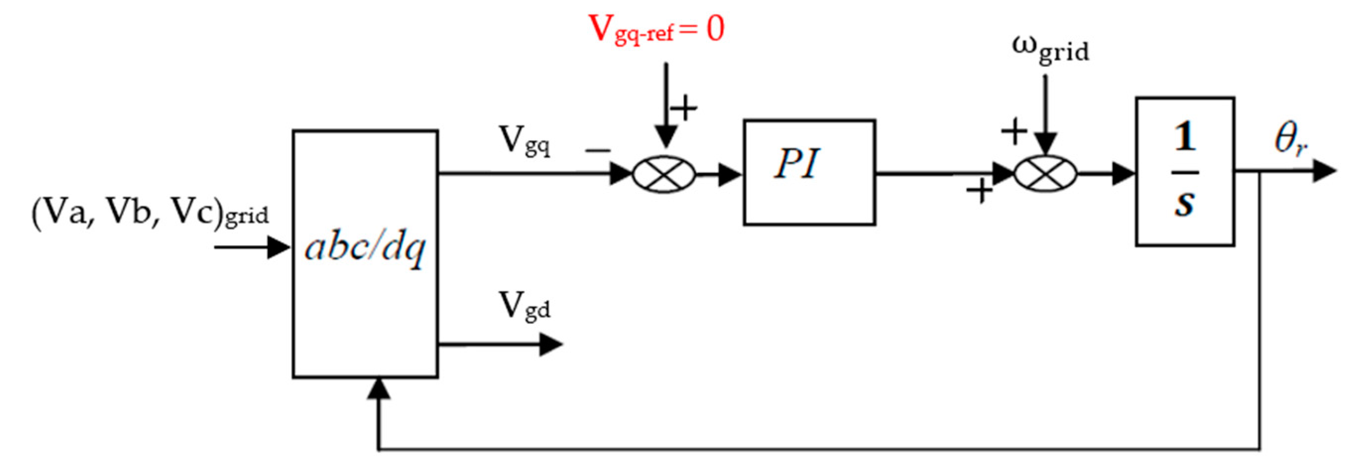
2.4. The Mathematical Model of the Grid

This mathematical model is described by the following equations [21,25]:
V g d = V i d R g   I g d L g   d I g d d t + ω g r i d   L g   I g q V g q = V i q R g   I g q L g   d I g q d t ω g r i d   L g   I g d
where:
Vgd and Vgq are the d-q components of the grid voltage.
Vid and Viq are the d-q components of the output voltage inverter.
Igd and Igq represent the d-q axis components of the current measured on the grid.
ω g r i d is the grid frequency.
The expression of the active and reactive power supplied to the grid by the wind turbine is listed below [17,24].
P g = 3 2 V g d I g d + V g d I g d Q g = 3 2 V g q I g d V g d I g q  

3. The Studied Control Strategy

This section describes the commands used to control the wind turbine system. Control of the asynchronous machine is ensured by the rectifier, and the inverter makes it possible to control the DC bus voltage and the reactive power, and to synchronize everything with the network.

3.1. DTC Applied to Asynchronous Machine

Direct torque control (DTC) is a technique increasingly used for controlling the voltage inverter–asynchronous machine system. This system can be considered as a hybrid dynamic system whose continuous component is the asynchronous machine and discrete component is the voltage inverter [26].
This control was introduced in 1985 by DEPENBROCK and TAKAHASHI [26]. The principle of this type of control is to ensure the flux and torque objectives; the latter are directly imposed by a judicious choice of the voltage vector imposed by the converter power supply. In this strategy, the quantities, which are the stator flux and the electromagnetic torque, are calculated from the quantities linked to the stator.
DTC applied to an asynchronous machine is based on direct determination of the control sequence applied to the switches of a voltage inverter. This choice is generally based on the use of hysteresis comparators whose function is to control the state of the system, for example, the amplitude of stator flux and electromagnetic torque. A voltage inverter allows seven distinct positions to be reached in the phase plane, corresponding to the eight sequences of the voltage vector at the inverter output (Vs) [6,26,27,28,30,31].
The DTC of the asynchronous machine applied in this study is shown in the following diagram.
The converter control sequences (Sa, Sb, Sc)IG are determined from the stator voltage vector (Vs). The relationship between the two quantities (illustrated by system 2 in Figure 2) is given in Table 1 [22,28,30,32,33].
The choice of the stator voltage vector (Vs) depends on the controlled variation of the stator flux modulus ( Φ s ) given by the parameter ( K Φ ) , on the stator flux location sector in the (α, β) plane given by the parameter (n), and also on the controlled evolution of the electromagnetic torque given by the parameter ( K c e ) [22,34].
Thus, the control parameters ( K Φ ) and ( K c e ) are the outputs of the two-level and three-level hysteresis comparators, respectively. The hysteresis comparators used to control the modulus of the stator flux and the electromagnetic torque are given by Equation (13) and Equation (14), respectively. The location of the stator flux vector in the plane (α, β) is given by Equation (15) [22,34,35].
i f   Φ s > ε Φ t h e n   K Φ = 1 i f   0 < Φ s < ε Φ a n d   d Φ s d t > 0 t h e n   K Φ = 0 i f   0 < Φ s < ε Φ a n d   d Φ s d t < 0 t h e n   K Φ = 1 i f   Φ s < ε Φ t h e n   K Φ = 1
i f   C e m > ε Φ t h e n   K c e = 1 i f   0 C e m ε e m d C e m d t > 0 t h e n   K c e = 0 i f   0 C e m ε e m d C e m d t < 0 t h e n   K c e = 1 i f   C e m ε e m t h e n   K c e = 1 i f   ε e m C e m < 0 d C e m d t > 0 t h e n   K c e = 0 i f   ε e m C e m < 0 d C e m d t < 0 t h e n   K c e = 1
n = tan 1 Φ s β Φ s α
where:
Φ s = Φ s r e f Φ s
Φ s = Φ s α 2 Φ s β 2
C e m = C e m r e f C e m
Notations:
Φ s r e f and C e m r e f are the flux and torque reference values.
The estimated values of the stator flux and the torque of the machine (illustrated by system 1 in Figure 2) are given by Equations (19) and (20) [22,34,36]:
Φ s α = 0 t V s α R s I s α d t Φ s β = 0 t V s β R s I s β d t
C e m = p ( Φ s α I s α Φ s β I s β )
The voltages and currents in the plane (α, β) are calculated using the Concordia transformer of the currents (Ia, Ib, Ic)IG and voltage (Va, Vb, Vc)IG measured at the level of the stator of the machine, as shown in Equations (21) and (22) [22,34].
V s α V s β = 1 3 2 1 2 1 2 0 3 2 3 2 V a V b V c
I s α I s β = 1 3 2 1 2 1 2 0 3 2 3 2 I a I b I c
The reference value of the stator flux is fixed to that of the stator flux of the machine at steady state. The reference electromagnetic torque is determined by using the MPPT strategy. This strategy consists of controlling the speed of the asynchronous machine at an optimal value to recover the maximum power from the wind. This strategy is given by Equation (23) [21,34].
C e m r e f = Ω t r e f Ω t m e a s K p _ m p p t K i _ m p p t S
where:
Ω t r e f = λ o p t R V w i n d

3.2. Control Connection between the Asynchronous Machine and the Grid

Figure 3 shows the details of the control strategy, and two control loops can be identified. The network current management is ensured by the internal loop, and the external loop ensures the control of the DC bus voltage and reactive power [4,20,21,34].
To inject the generated energy into the electrical grid, a synchronization of the output voltage of the inverter with the grid voltage is necessary. This synchronization is carried out by using a phase-locked loop (PLL) [4,20,21]. The PLL also ensures the decoupling of the active and reactive power, as shown in Equation (25), by controlling the voltage component, Vgq, at zero [4,20,21,25]. The structure of the PLL used is shown in Figure 4.
P r = 3 2   V r d   I r d         Q r = 3 2 V r d   I r q    
If the converter efficiency is equal to 1, the relationship between the DC bus and active power injected in the grid is given by Equation (25) [21,25].
For the control, proportional integral (PI)-type controllers were used. The determination of the coefficients (Kp, Ki) of these controllers was based on the pole placement method.
The Pulse Width Modulation (PWM) strategy was used to generate the signals (Sa, Sb, Sc)inv.
To test the robustness of the control, large variations in wind speed were applied, as shown in Figure 5.
The electromagnetic torque and the mechanical speed for a variable torque setpoint can be found in Figure 6 and Figure 7 below. In these figures, the good performance of the torque control can be observed. The electromagnetic torque precisely follows its reference. Likewise, the speed follows its reference, and they also quickly establish themselves in the transition phase without overshooting.
The modulus and trajectory of the stator flux vector are presented in Figure 8 and Figure 9, respectively. It can be noted that the flow trajectory maintains a practically circular shape throughout the torque variation. This shows that by applying the principles of direct torque control, the electromagnetic torque can be controlled while controlling the magnitude of the flux around its setpoint. We can conclude that DTC offers good dynamic performance.
The currents injected into the electrical networks are given in Figure 10. The network side converter must ensure synchronism with the electrical network at the injection point, and this function is ensured by the phase-lock loop. This observation of synchronism is shown by the zoom of the phases (a, b, c) of current injected in the electrical grid by the wind turbine (Figure 11).
This converter is also used to effectively set the DC bus voltage to its reference value, as shown in Figure 12. The parameters of the system studied are given in Appendix A.

4. Rs Impact on DTC

As shown in Equation (19), the stator winding resistance is the only parameter that needs to be known by the control system (DTC). During operation, this resistance varies. The main cause of variation in the stator resistance of the asynchronous machine is generally the load variation and ambient temperature. This varies almost irregularly during operation [21,32,35,37].
The error between the actual value of the stator resistance of the asynchronous machine and the value used by the DTC control unit causes an error in the estimation of the stator flux and the electromagnetic torque, which can cause control instability by applying sequences that do not conform to the operating state [22].
The works cited in [22,32,35,36,38] have highlighted the influence of this variation and have calculated the deviation between the estimated values ( C e m , Φ s ) and their real values as a function of the real resistance R s r of the machine and the resistance R s used in the flux and torque estimation. These deviations are given in the equations below:
C e m = p R s r R s ω s I s 2
Φ s S = ( R s r R s ) I s
To analyze this problem, a test was carried out. In this test, the resistance value R s used by the DTC control block is lower than the real stator resistance R s r of the asynchronous machine. Practically, there is an increase in the real value of the stator resistance. This graduated variation in the actual stator resistance is illustrated in Figure 13.
According to Figure 14, Figure 15 and Figure 16 for the electromagnetic torque and the stator flux of the asynchronous machine, the control is degraded by this parametric variation. The compensation for this parameter variation is essential to make the DTC robust.

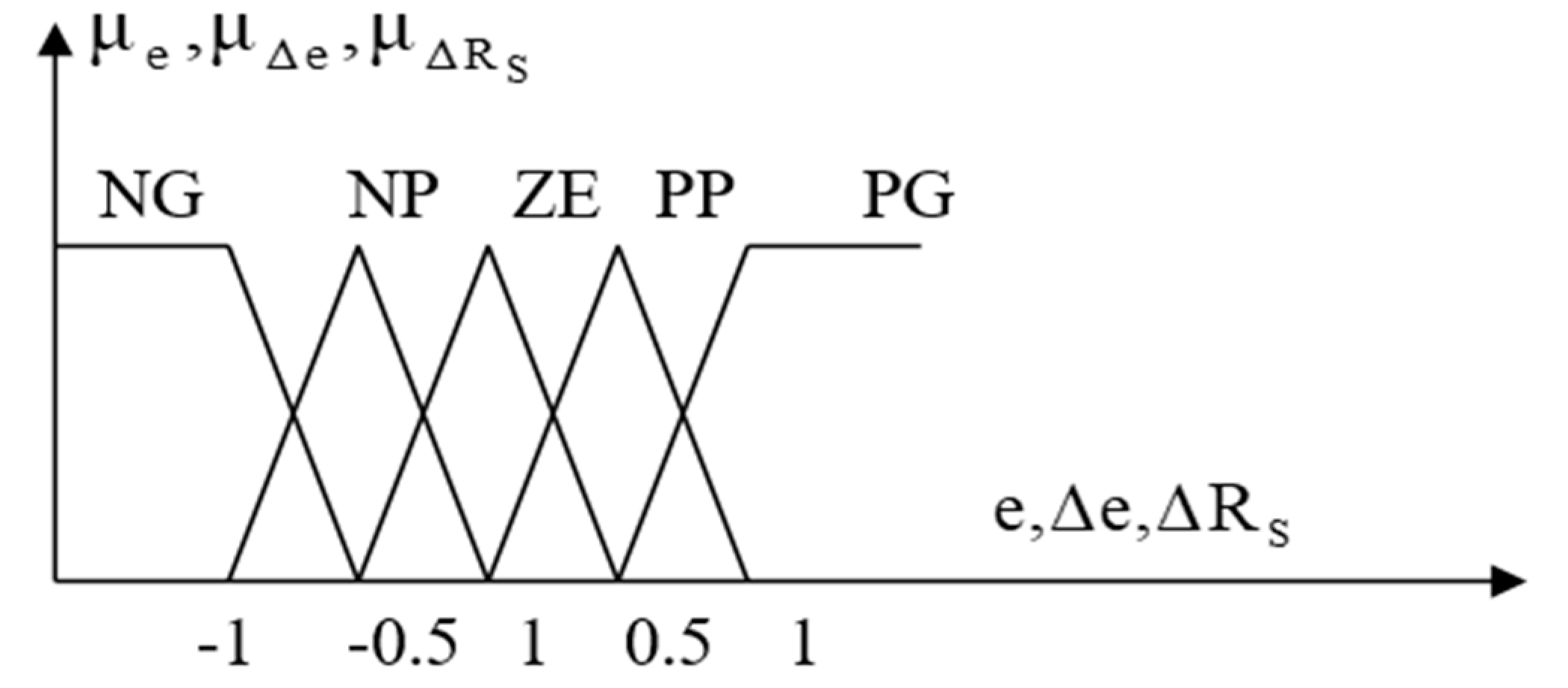
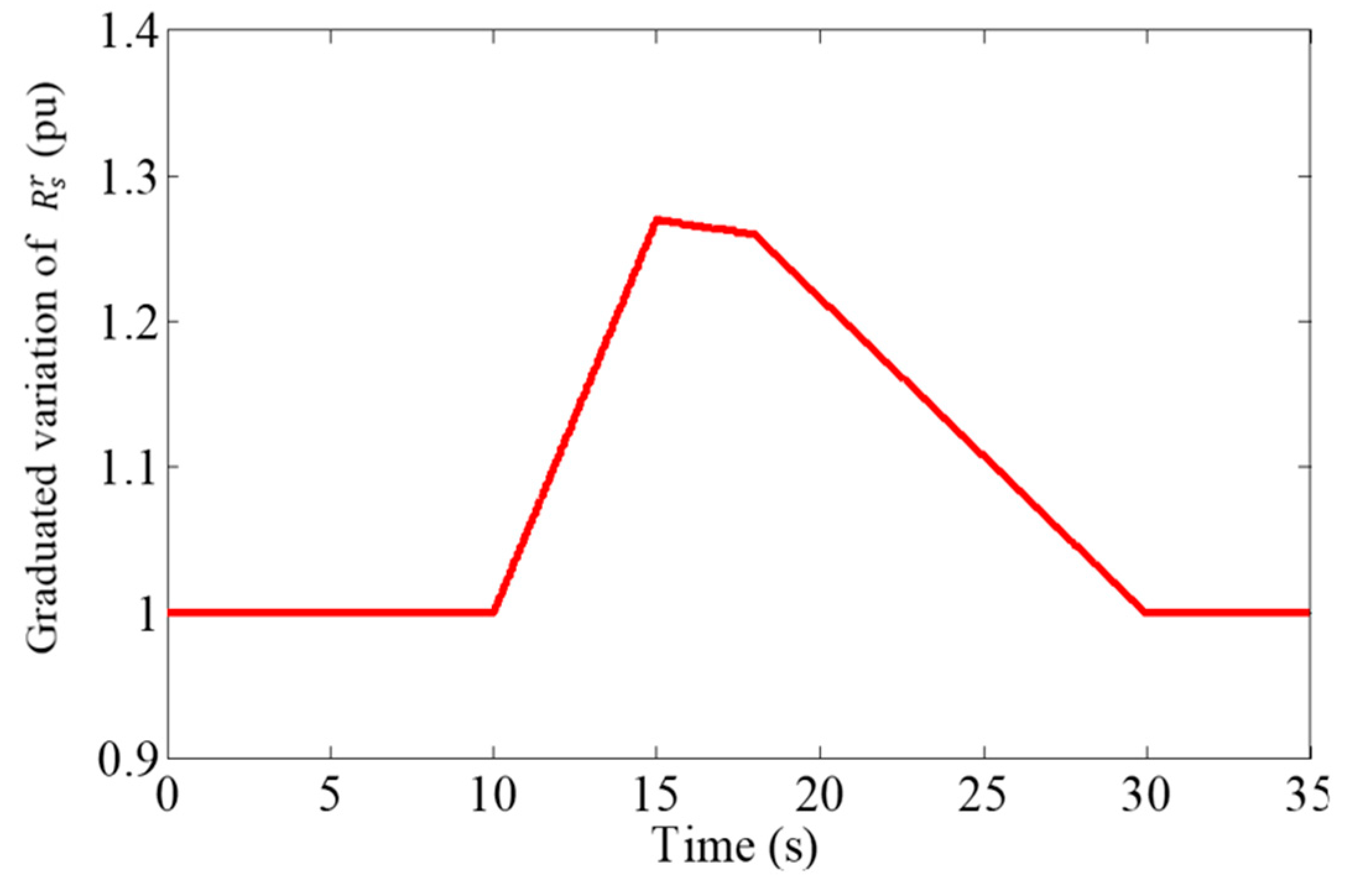
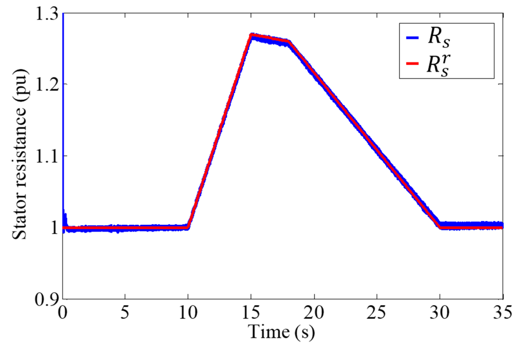
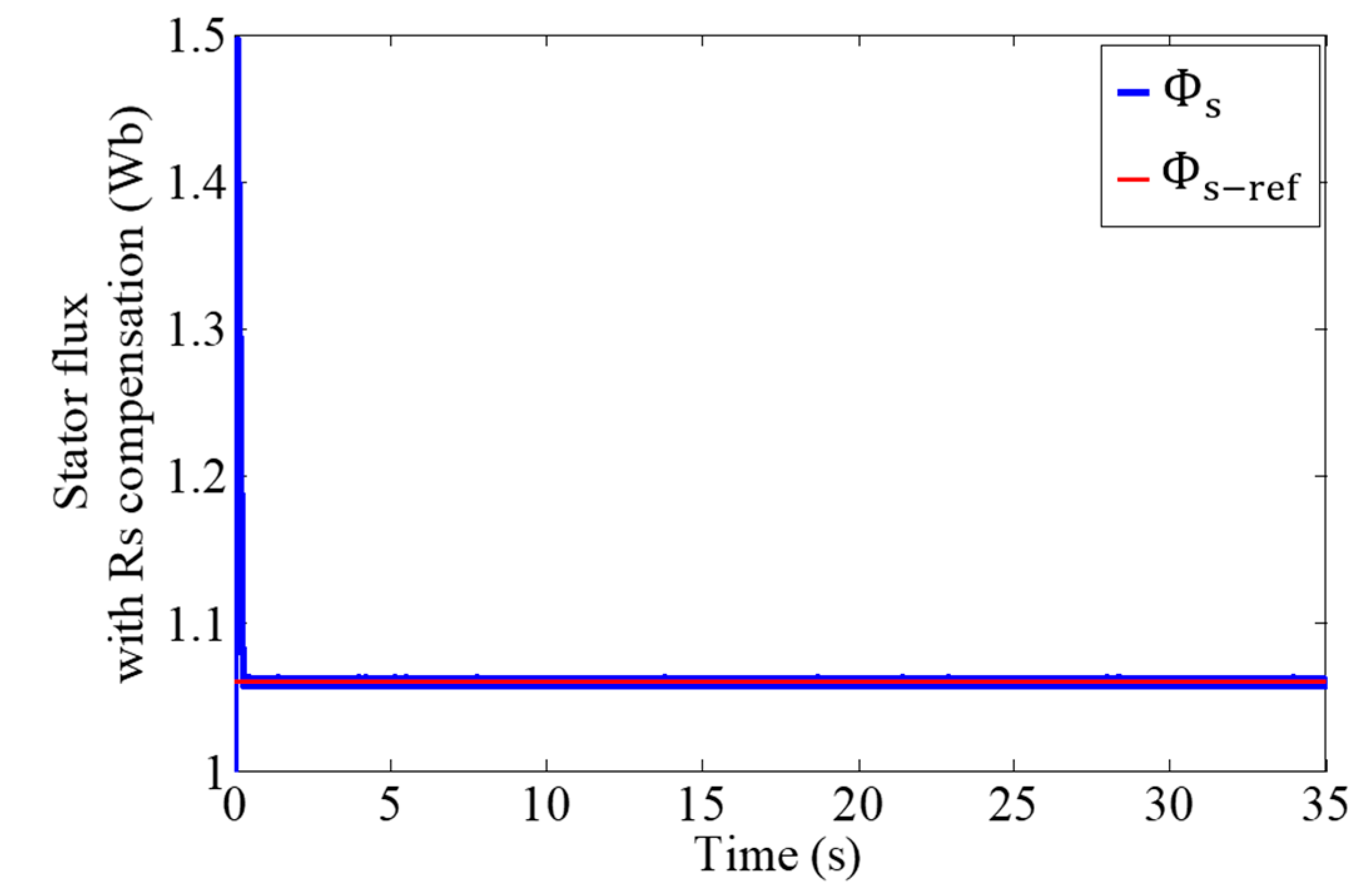
DTC Improved by the Fuzzy Estimator

The study of the influence of the variation in stator resistance on the stability and robustness of the DTC method led to the conclusion that it was necessary to compensate in order to avoid any instability in the control. The strategy is therefore to find a physical parameter that does not depend on the variation in stator resistance. In this study, the measured stator current and its reference value are used [20,21].
The asynchronous machine reference stator current I s * is estimated from an invariant model which does not consider the evolution of the stator resistance during operation (illustrated by system (3) in Figure 17 below).
This reference current is undoubtedly subject to error with respect to the actual current I s absorbed by the motor [20,30] due to the discrepancy between the values R s r and R s . This discrepancy will be reduced by estimating the real value of the stator resistance in the DTC control block using a fuzzy estimator.
The difference between the estimated stator current and the actual machine current (Equation (28)), and the variation in this difference (Equation (29)), are used as fuzzy input variables of the fuzzy estimator, whose block diagram is illustrated in Figure 17 and Figure 18 [20,30].
e ( k ) = I s * ( k ) I s ( k )
e ( k ) = e ( k ) e ( k 1 )
The fuzzification of the input and output variables of the fuzzy estimator is illustrated in Figure 19; each of the three linguistic variables is represented by five fuzzy subsets (NL ≡ Negative Large, NS ≡ Negative Small, ZE ≡ Null, PS ≡ Positive Small, and PL ≡ Positive Large) [20,23,37,38,39].
Defuzzification was also carried out using the center of gravity method combined with the sum-product inference method. In this case, the simplified form is given by the following relationship [20,30]:
R s = i = 1 25 μ G i x G i s i i = 1 25 μ G i s i
where:
μ G i : is the modification coefficient to be applied to the ith subset of output R s .
x G i , s i : are the abscissa of the center of gravity and the area of the subset (i) of the output variable, respectively.
The 25 inference rules are summarized in Table 2.
The reasoning of this table of inference is deduced from the system of Equation (19). In fact, if the stator resistance increases at a given voltage and flux, the motor stator current decreases [15,40].
We therefore need to reduce the stator current and force it to follow the real stator current of the asynchronous machine. To do this, we increase the estimated stator resistance. So, we increase Rs for a decrease in compared with I s * , and vice versa.
For example, for (e) Positive Large (PL) and (∆e) Positive Large (PL), (∆Rs) must also be Positive Large (PL), etc. And following this logic, we can justify all the other rules in the table above.
The reference current I s * (Equation (31)) is determined by calculating its two components Isd and Isq. These two components are determined by Equations (32) and (33). The I d s * is the smallest of the solutions found for Equation (33) [30].
I s * = I d s * 2 + I q s * 2
I q s * = 2 3 p C e m r e f Φ s r e f
L s I d s * 2 Φ s r e f 1 L s L r L m 2 L s L r I d s * = L r L m 2 L s L r Φ s r e f 2 L s I q s * 2
To test the robustness of the proposed fuzzy estimator, a realistic variation in the machine resistance R s r was applied, which was assumed to be equal to its nominal value between 0 and 10 s, and then increases linearly between 10 s and 15 s. This increase reaches a value of 27% of the nominal value after 5 s. The resistance then decreases between 15 s and 30 s until it reaches its nominal value, where it remains constant (Figure 20). To test the robustness of the control, large variations in wind speed were applied, as shown in Figure 5.
Figure 21 illustrates the evolution R s r proposed and estimated resistance R s (delivered by the proposed fuzzy compensator). An overshoot at start-up is observed between the two resistances, but a good estimate of the stator resistance in steady state implies a good correction of the electromagnetic torque and the stator flux.
Figure 22 and Figure 23 show the good compensation of the stator flux response using the fuzzy regulator. Indeed, this flux has been properly restored to its reference. We observe that the control stabilizes just after a short overshoot phase at start-up. The torque and the reference torque are illustrated in Figure 24; we note that the torque and its reference quantities are almost confused, and likewise for regulating the speed of the asynchronous machine in Figure 25. We also observe that during large variations in wind speed, the torque and speed follow the references just after slight shifts, and the control always remains stable.
The DC bus voltage is maintained at its reference even with large wind variations, as shown in Figure 26. The currents (Figure 27) produced by the wind generator injected into the network are of sinusoidal shape and have a frequency of 50 Hz (Figure 28). All the results show that the wind system is stable with the addition of this fuzzy regulator.
To evaluate the effectiveness of the proposed solution, the root mean square error index was used. Lower RMSE values indicate better solution performance.
The values of this index are 0.0376 when comparing electromagnetic torques (DTC and improved DTC) and 0.0014 when comparing stator fluxes (DTC and improved DTC). We observe that these values are very low, thus confirming the observations mentioned above.

5. Conclusions

This article is devoted to the study of the influence of the variation in stator resistance on the robustness and stability of the DTC of a wind turbine based on an asynchronous machine. Detailed simulation results are presented and commented on.
Extreme variation tests were studied. The goal was to judge the effectiveness of the fuzzy estimator, which intervenes to correct a deviation in this key parameter and to compensate for the torque and flux estimation errors caused by this same deviation.
According to the results obtained by the insertion of a fuzzy regulator to estimate the stator resistance, we note the compensating effect of this estimator of the variation in the stator resistance. This restored the stability of the system and reinforced the robustness of the DTC control of the machine with respect to large variations in stator resistance during operation.
In future works, we intend to compare the effectiveness of this DTC method with conventional controls such as vector control in transient regimes (for example, the ability to withstand voltage drops in the network).

Author Contributions

Conceptualization, D.I. and E.R.; Methodology, D.I. and E.R.; Software, D.I. Validation, D.I. and E.R.; Investigation, D.I. and E.R.; Writing—original draft preparation, D.I.; Writing—review and editing, D.I. and E.R.; Visualization, D.I. and E.R; Supervision, D.I. and E.R. All authors have read and agreed to the published version of the manuscript.

Funding

This research received no external funding.

Data Availability Statement

The original contributions presented in the study are included in the article, further inquiries can be directed to the corresponding author.

Conflicts of Interest

The authors declare no conflicts of interest.

Appendix A

Table A1. Index.
Table A1. Index.
SymbolsParametersUnit (SI)
ρAir densitykg/m3
RBlade radiusm
VwWind speedm/s
λTip speed ratio (TSR) of the rotor bladeN/A
βBlade pitch angledeg
RsStator resistanceOhm
RrRotor resistanceOhm
LrRotor inductanceHenry
LsStator inductanceHenry
LmMutual inductanceHenry
pNumber of pole pairsN/A
ωsStator frequencyHrz
ωrRotor frequencyHrz
JRotor inertiaKg·m2
CrLoading torqueN/m
frFriction coefficientNm/(rad/s)
LgInductance component of the filterHenry
RgResistance component of the filterOhm
Kp-mpptParameter of PI controller for MPPT loop.
Ki-mpptParameter of PI controller for MPPT loop.
SLaplace operator
Table A2. Wind turbine parameters [41].
SymbolsParametersUnit (SI)
Rs0.0089 Ohm
Rr0.0137Ohm
Lr0.01267Henry
Ls0.01292Henry
Lm0.01267Henry
p2-
Lg0.0005Henry
Rg0.00001Ohm
J10Kg·m2
fr0.00001Nm/(rad/s)
R13.5m
Pmax300 kW
Vdc760V
Rs0.0089 Ohm

References

  1. García-Sánchez, T.; Gómez-Lázaro, E.; Molina-García, A. A review and discussion of the grid-code requirements for renewable energy sources in Spain. In Proceedings of the International Conference on Renewable Energies and Power Quality (ICREPQ’14), Cordoba, Spain, 8–10 April 2014; pp. 565–570. [Google Scholar] [CrossRef]
  2. E.ON Netz GmbH. Requirements for Offshore Grid Connections in the E.ON Netz Network; E.ON Netz GmbH: Bayreuth, Germany, 2008. [Google Scholar]
  3. Elkodama, A.; Ismaiel, A.; Abdellatif, A.; Shaaban, S.; Yoshida, S.; Rushdi, M.A. Control Methods for Horizontal Axis Wind Turbines (HAWT): State-of-the-Art Review. Energies 2023, 16, 6394. [Google Scholar] [CrossRef]
  4. Djamel, I. Marine Energy Production: Integration of Offshore Wind Production into a Decentralized Energy Mix. Ph.D. Thesis, Le Havre University, Le Havre, France, 2014. [Google Scholar]
  5. Meziane, S. Commande Adaptative et Prédictive de la Machine Asynchrone. Ph.D. Thesis, University of Constantine, Constantine, Algeria, 2009. [Google Scholar]
  6. Sellah, M.; Kouzou, A.; Mohamed-Seghir, M.; Rezaoui, M.M.; Kennel, R.; Abdelrahem, M. Improved DTC-SVM Based on Input-Output Feedback Linearization Technique Applied on DOEWIM Powered by Two Dual Indirect Matrix Converters. Energies 2021, 14, 5625. [Google Scholar] [CrossRef]
  7. Ortega-García, L.E.; Rodriguez-Sotelo, D.; Nuñez-Perez, J.C.; Sandoval-Ibarra, Y.; Perez-Pinal, F.J. DSP-HIL Comparison between IM Drive Control Strategies. Electronics 2021, 10, 921. [Google Scholar] [CrossRef]
  8. Sahri, Y.; Tamalouzt, S.; Lalouni Belaid, S.; Bacha, S.; Ullah, N.; Ahamdi, A.A.A.; Alzaed, A.N. Advanced Fuzzy 12 DTC Control of Doubly Fed Induction Generator for Optimal Power Extraction in Wind Turbine System under Random Wind Conditions. Sustainability 2021, 13, 11593. [Google Scholar] [CrossRef]
  9. Barambones, O. Sliding Mode Control Strategy for Wind Turbine Power Maximization. Energies 2012, 5, 2310–2330. [Google Scholar] [CrossRef]
  10. Rania, G.M.; Ebrahim, M.A.; Zuhair, M.A.; Ahmed, M.M.R. Optimal Energy Harvesting of Large-Scale Wind Farm Using Marine Predators Algorithm. IEEE Access 2022, 7, 225–238. [Google Scholar] [CrossRef]
  11. Djamel, I.; Elena, R. Comparative Study Between the Flatness-Based and Field-Oriented Control of a Wind-Energy System. In Proceedings of the International Symposium on Electrical and Electronics Engineering (IEEE-ISEEE), Galați, Romania, 28 October 2021; pp. 1–7. [Google Scholar] [CrossRef]
  12. Haque, M.E.; Rahman, M.F. Influence of Stator Resistance Variation on Direct Torque Controlled. In Proceedings of the Thirty-Sixth IEEE Industry Applications Conference (IAS), Chicago, IL, USA, 30 September–4 October 2001. [Google Scholar]
  13. El Ouanjli, N.; Motahhir, S.; Derouich, A.; El Ghzizal, A.; Taoussi, M.; Chebabhi, A. Improved DTC strategy of doubly fed induction motor using fuzzy logic controller. Energy Rep. 2019, 5, 271–279. [Google Scholar] [CrossRef]
  14. Soedibyo, S.; Feby, A.P.; Ashari, M. Control Design of Wind Turbine System Using Fuzzy Logic Controller for Middle Voltage Grid. Indones. J. Electr. Eng. Comput. Sci. 2015, 3, 476–482. [Google Scholar] [CrossRef]
  15. Almaged, M.; Mahmood, A.; Alnema, Y.H.S. Design of an Integral Fuzzy Logic Controller for a Variable—Speed Wind Turbine Model. J. Robot. Control. 2023, 4, 762–768. [Google Scholar] [CrossRef]
  16. Mabrouk, Y.A.; Mokhtari, B.; Allaoui, T. Frequency analysis of stator currents of an induction motor controlled by direct torque control associated with a fuzzy flux estimator. Electr. Eng. Electromech. 2023, 27–32. [Google Scholar] [CrossRef]
  17. Teggar, T. Comparative Study between Flux Vector Control Orients and Direct Control of the Torque of the machine Asynchronous. Engineering Thesis, University of Ouargla, Ouargla, Algeria, May 2016. [Google Scholar]
  18. Fathy, A.; Yousri, D.; Rezk, H.; Thanikanti, S.B.; Hasanien, H.M. A Robust Fractional-Order PID Controller Based Load Frequency Control Using Modified Hunger Games Search Optimizer. Energies 2022, 15, 361. [Google Scholar] [CrossRef]
  19. Djamel, I.; Camara, M.B.; Dakyo, B. Offshore wind farms energy injection in the electrical grid—Lithium battery to mitigate power fluctuations. Int. J. Renew. Energy Res. 2015, 5, 1050–1061. [Google Scholar] [CrossRef]
  20. Djamel, I. Direct Control of the Torque of an Asynchronous Machine with Fuzzy Estimator of the Stator Resistance. Engineering Thesis, University of Bejaia, Bejaia, Algeria, July 2007. [Google Scholar]
  21. Mokrani, L.; Abdessemed, R.; Bendias, M.L. Fuzzy estimator of the stator resistance of an induction motor controlled by neural DTC. In Proceedings of the International Conference on Electrical and Electronics Engineering (ICEEE), Laghouat, Algeria, 24–26 April 2004. [Google Scholar]
  22. Mansour, M.; Mansouri, M.N.; Mmimouni, M.F. Study and Control of a Variable-Speed Wind-Energy System Connected to the Grid. Int. J. Renew. Energy Res. 2011, 1, 96–104. [Google Scholar] [CrossRef]
  23. Jnayah, S.; Moussa, I.; Khedher, A. IM Fed by Three-Level Inverter under DTC Strategy Combined with Sliding Mode Theory. Electronics 2022, 11, 3656. [Google Scholar] [CrossRef]
  24. Maes, J.; Melkebeek, J.A. Speed-sensorless direct torque control of induction motors using an adaptive flux observer. IEEE Trans. Ind. Appl. 2000, 36, 778–785. [Google Scholar] [CrossRef]
  25. Martins, C.A.; Roboam, X.; Meynard, T.A.; Carvalho, A.S. Switching frequency imposition and ripple reduction in DTC drives by using a multilevel converter. IEEE Trans. Power Electron. 2002, 17, 286–297. [Google Scholar] [CrossRef]
  26. de Barros, J.C. Application de la logique floue à la commande optimale du moteur asynchrone. Ph.D. Thesis, Aix-Marseille III University, Marseille, France, 2003. [Google Scholar]
  27. Elgbaily, M.; Anayi, F.; Alshbib, M.M. A Combined Control Scheme of Direct Torque Control and Field-Oriented Control Algorithms for Three-Phase Induction Motor: Experimental Validation. Mathematics 2022, 10, 3842. [Google Scholar] [CrossRef]
  28. Esparza Sola, T.; Chiu, H.-J.; Liu, Y.-C.; Rahman, A.N. Extending DC Bus Utilization for Induction Motors with Stator Flux Oriented Direct Torque Control. Energies 2022, 15, 374. [Google Scholar] [CrossRef]
  29. Buja, Y.G.; Menis, R. Steady-State Performance Degradation of a DTC IM Drive Under Parameter and Transduction Errors. IEEE Trans. Ind. Electron. 2008, 55, 1749–1760. [Google Scholar] [CrossRef]
  30. Mokhtari, B. Intelligent DTC applied to asynchronous machine control. Ph.D. Thesis, University of Batna, Batna, Algeria, July 2014. [Google Scholar]
  31. Bermúdez, M.; Barrero, F.; Martín, C.; Perales, M. Performance Analysis of Direct Torque Controllers in Five-Phase Electrical Drives. Appl. Sci. 2021, 11, 11964. [Google Scholar] [CrossRef]
  32. Lai, Y.-S.; Chen, J.-H. A new approach to direct torque control of induction motor drives for constant inverter switching frequency and torque ripple reduction. IEEE Trans. Energy Convers. 2001, 16, 220–227. [Google Scholar] [CrossRef]
  33. Aziz, A.G.M.A.; Abdelaziz, A.Y.; Ali, Z.M.; Diab, A.A.Z. A Comprehensive Examination of Vector-Controlled Induction Motor Drive Techniques. Energies. 2023, 16, 2854. [Google Scholar] [CrossRef]
  34. Cabrera, L.A.; Elbuluk, M.E.; Husain, I. Tuning the stator resistance of induction motors using artificial neural network. IEEE Trans. Power Electron. 1997, 12, 879–886. [Google Scholar] [CrossRef]
  35. Lee, B.S.; Krishnan, R. Adaptive Stator Resistance Compensator for High Performance Direct Torque Controlled Induction Motor Drive. In Proceedings of the IEEE IAS Annual Meeting, St. Louis, MO, USA, 12–15 October 1998; pp. 423–430. [Google Scholar] [CrossRef]
  36. Bayoumi, E.H.E. Multi-resolution analysis wavelet PI stator resistance estimator for direct torque induction motor drive. WSEAS Trans. Circuits Syst. 2013, 12, 211–220. [Google Scholar]
  37. Zidani, F.; Diallo, D.; Benbouzid, M.E.H.; Nait-Said, R. Direct Torque Control of Induction Motor With Fuzzy Stator Resistance Adaptation. IEEE Trans. Energy Convers. 2006, 21, 619–621. [Google Scholar] [CrossRef]
  38. Varga, T.; Benšić, T.; Barukčić, M.; Štil, V.J. Optimization of Fuzzy Controller for Predictive Current Control of Induction Machine. Electronics 2022, 11, 1553. [Google Scholar] [CrossRef]
  39. Kakouche, K.; Oubelaid, A.; Mezani, S.; Rekioua, D.; Rekioua, T. Different Control Techniques of Permanent Magnet Synchronous Motor with Fuzzy Logic for Electric Vehicles: Analysis, Modelling, and Comparison. Energies 2023, 16, 3116. [Google Scholar] [CrossRef]
  40. Kroičs, K.; Būmanis, A. BLDC Motor Speed Control with Digital Adaptive PID-Fuzzy Controller and Reduced Harmonic Content. Energies 2024, 17, 1311. [Google Scholar] [CrossRef]
  41. Salma, E.A. Modeling of different wind turbine technologies integrated into a medium voltage network. Ph.D. Thesis, Ecole Central de Lille, Lille, France, 2004. [Google Scholar]
Figure 1. Block diagram of the wind system.
Energies 17 02488 g001
Figure 2. DTC strategy [4,20].
Energies 17 02488 g002
Figure 3. Control system between the MAS and the grid [11,19].
Energies 17 02488 g003
Figure 4. Phase-locked loop.
Energies 17 02488 g004
Figure 5. Applied wind profile.
Energies 17 02488 g005
Figure 6. Electromagnetic torque.
Energies 17 02488 g006
Figure 7. Mechanical speed.
Energies 17 02488 g007
Figure 8. Stator flux.
Energies 17 02488 g008
Figure 9. Stator flux trajectory in (α,β) plan.
Energies 17 02488 g009
Figure 10. Amplitudes of the current injected in the grid.
Energies 17 02488 g010
Figure 11. Form of the currents injected in the grid.
Energies 17 02488 g011
Figure 12. DC bus voltage.
Energies 17 02488 g012
Figure 13. Graduated variation in the stator resistance R s r .
Energies 17 02488 g013
Figure 14. Electromagnetic torque without RS compensation.
Energies 17 02488 g014
Figure 15. Stator flux without RS compensation.
Energies 17 02488 g015
Figure 16. Stator flux trajectory in the plane (α,β) without RS compensation.
Energies 17 02488 g016
Figure 17. DTC system of MAS with Rs estimated [4,20].
Energies 17 02488 g017
Figure 18. Block diagram of a fuzzy PI used to estimate Rs [20].
Energies 17 02488 g018
Figure 19. Fuzzification of the fuzzy linguistic variables of the Rs estimator.
Energies 17 02488 g019
Figure 20. Proposed evolution of stator resistance.
Energies 17 02488 g020
Figure 21. Stator resistance with Rs compensation.
Energies 17 02488 g021
Figure 22. Stator flux with RS compensation.
Energies 17 02488 g022
Figure 23. Stator flux trajectory in the plane (α,β) with RS compensation.
Energies 17 02488 g023
Figure 24. Electromagnetic torque with RS compensation.
Energies 17 02488 g024
Figure 25. Mechanical speed with RS compensation.
Energies 17 02488 g025
Figure 26. DC bus voltage with RS compensation.
Energies 17 02488 g026
Figure 27. Currents injected in the grid with RS compensation.
Energies 17 02488 g027
Figure 28. Zoom on the currents injected in the grid with RS compensation.
Energies 17 02488 g028
Table 1. The relationship between (Vs) and (Sa, Sb, Sc)IG.
VsV0V1V2V3V4V5V6V7
(Sa, Sb, Sc)IG0 0 01 0 01 1 00 1 00 1 10 0 11 0 11 1 1
Table 2. Fuzzy inference rules for the R s estimator.
Δe
PLPSZENLNS
PLPLPLPLPSZE
PSPSPLPSZENS
eZEPLPSZENSNL
NLPSZENSNLNL
NSZENSNLNLNL
Disclaimer/Publisher’s Note: The statements, opinions and data contained in all publications are solely those of the individual author(s) and contributor(s) and not of MDPI and/or the editor(s). MDPI and/or the editor(s) disclaim responsibility for any injury to people or property resulting from any ideas, methods, instructions or products referred to in the content.

