Abstract
In recent years, the C4F7N mixed gas has attracted considerable attention for its outstanding insulation and arc-extinguishing capabilities, positioning it as a potential substitute for sulfur hexafluoride, SF6. However, there remains a limited understanding of the arc-extinguishing and insulation performance of C4F7N/CO2 mixed gas. In addition, there is limited research on high-current breaking in circuit breakers. Therefore, this study aims to investigate the arc characteristics and breaking behavior of 10%C4F7N/90%CO2 and 15%C4F7N/85%CO2 mixed gases using a magnetohydrodynamic model based on the 252kV air pressure circuit breaker. The dynamic characteristics of this mixed gas are compared with pure SF6 under short-circuit current breaking conditions, while analyzing different parameters of the C4F7N configuration. The results indicate that the mixed gas exhibits lower levels in terms of arc temperature, axial diffusion distance and pressure difference at the moment of arc initiation compared to pure SF6. Furthermore, increasing the inflating pressure can effectively enhance the breaking performance of the circuit breaker with 0.6 MPa, making it more suitable. Additionally, increasing the proportion of C4F7N in the mixed gases will cause the arc temperature to rise slightly at the initial arc and current crossing zero, but decrease at the peak current. The core pressure also rises significantly, with a greater pressure difference established in the compressor at moment of arc initiation. This study provides a reference for the design of an environmentally friendly circuit breaker and the selection of the mixed gas ratio.
1. Introduction
In high-voltage switchgear, SF6 is commonly utilized as the insulating medium [1,2,3]. However, due to its atmospheric lifetime of approximately 3200 years and a global warming potential 23,000 times that of CO2, SF6’s usage is restricted [4,5,6]. Therefore, finding an environmentally friendly gas with low greenhouse effects and an equivalent insulating performance to that of SF6 is a crucial task in the power industry. The new environmentally friendly gas C4F7N is currently one of the most promising alternatives to replace SF6, offering superior insulating performance and a shorter atmospheric lifetime, with only 10% of the global warming potential compared to SF6 [7,8,9,10,11]. It should be noted that C4F7N easily liquefies and requires mixing with conventional gases in practical applications to reduce the liquefaction temperature [12].
At present, domestic and international scholars are conducting comprehensive research on the performance of C4F7N and its mixed gases, exploring them from both macroscopic and microscopic perspectives in order to unveil their micro mechanisms and establish a theoretical foundation for optimizing and enhancing the performance of C4F7N and its mixed gas. N2 and CO2 are commonly employed as buffer gases in mixed gases, with research findings indicating that the use of CO2 as a buffer gas yields superior results. Furthermore, the addition of trace amounts of C4F7N to CO2 can significantly enhance the insulation performance of the mixed gas. As the content or pressure of C4F7N increases, so does the insulation strength of the mixed gas [13,14]. The breakdown voltage of the mixed gas tends to saturate gradually with increasing pressure and C4F7N ratio. Under the same conditions, the breakdown voltage of the mixed gas containing 10%C4F7N/90%CO2 is approximately 80% that of pure SF6, while the breakdown voltage of the mixed gas containing 20%C4F7N/80CO2 is about 95% that of pure SF6. The use of 4–12% C4F7N demonstrates significant potential for application [15,16]. Through the investigation of the insulation properties of C4F7N/CO2 mixed gas under varying electric field conditions, it was observed that in a non-uniform electric field, the breakdown strength of the mixed gas is inversely related to the electric field’s non-uniformity coefficient and positively correlated with pressure. In scenarios of lightning strikes, the mixed gas must be pressurized to 0.8 MPa in order to achieve 80% of the insulation strength of SF6 gas at 0.4 MPa under highly non-uniform electric fields [17,18]. The literature has investigated the extinguishing performance of mixed gas under micro-positive pressure, comparing the voltage characteristics and dielectric recovery characteristics of mixed gas. The experimental results indicate that, under micro-positive pressure, the arc voltage of mixed gas is similar to that of SF6 gas, but the arc radius of mixed gas is larger and more easily converted in reverse. At the same breaking current, the dielectric recovery strength of mixed gas is only 30% that of pure SF6 gas, while also exhibiting stronger radial cooling ability [19,20]. The insulation stability of mixed gases has been extensively investigated in the literature. Based on both experimental and computational findings, it is concluded that the insulation stability of C4F7N/CO2 mixed gas is significantly lower than that of SF6 gas under similar conditions. In non-uniform electric fields, the mixed gas exhibits a higher susceptibility to partial discharge; concurrently, the electric field distribution within electrical equipment exerts a greater influence on the insulation performance of the mixed gas. Therefore, when utilizing mixed gases, careful consideration should be given to the internal structural design in order to mitigate the impact of non-uniform electric fields on insulation performance [21]. In order to more accurately and efficiently study the breaking capacity of circuit breakers, numerical simulation methods are commonly employed for research. This approach can simulate various physical phenomena involved in the breaking process of circuit breakers, including the coupling phenomenon of multiple physical fields, such as temperature, airflow, radiation, and electromagnetic fields. Currently, most research is focused on the insulation characteristics of mixed gas, with relatively limited investigation into the breaking characteristics of mixed gas [22,23]. Therefore, it is imperative to investigate the breaking characteristics and influencing factors of mixed gas in circuit breakers.
In this paper, a mathematical model for a multi-physical field coupling arc is established to simulate the arc temperature and pressure of the arc chamber in a 252 kV compressed air circuit breaker under short-circuit current. The calculation results reveal the variation trend and distribution characteristics of the mixed gas arc temperature, arc chamber pressure, and other parameters, which are then compared with SF6 arc characteristics. Additionally, the influence of different charging pressures and C4F7N proportions on the mixed gas arc characteristics is investigated to clarify the extinguishing mechanism of C4F7N/CO2 mixed gases.
2. Mathematical Modeling of Electric Arc
2.1. Fundamental Equation Governing the System
During the arcing process in a nozzle, it is assumed that the arc and the surrounding gas are in local thermodynamic equilibrium, and due to the symmetrical nature of the nozzle structure, the physical process can be effectively described by the time-averaged Navier–Stokes (RANS) equation.
The mass conservation equation is as follows:
The momentum conservation equation is as follows:
The energy conservation equation is as follows:
The electromagnetic equations are as follows:
The equation for the Lorentz force is given below:
2.2. Turbulence Model
In the field of fluid dynamics, the k-ε turbulence model is widely employed as a numerical simulation method to describe the motion of fluids in turbulent states. Derived from the Navier–Stokes equation, this model introduces two equations, governing turbulent kinetic energy (k) and the viscous diffusion rate (ε). In this framework, k represents the energy associated with turbulent motion, while ε characterizes the impact of viscous diffusion on turbulence. These equations effectively capture the dynamic and thermodynamic processes in turbulent flow fields, thereby providing robust support for research and engineering applications in fluid dynamics. The k-ε turbulence model incorporates five constants, outlined in Table 1, which are determined through a combination of experimental data and theoretical analysis during its development [24]. These constants play a critical role in ensuring the accuracy and applicability of the turbulence model, exerting a significant influence on the calculation results. Therefore, it is essential to select appropriate constant values, based on specific flow environments and working conditions, to achieve optimal simulation outcomes. The values listed in Table 2 should be used for different gas calculations.

Table 1.
Symbols and their units.
Table 2.
Values of the five parameters in the k-ε model.
2.3. Radiation Model
Currently, there are numerous radiation models available, including the P1 model, the partial characteristic method, and the semi-empirical model. The P1 model requires solving five additional equations, which have slow convergence speeds and high computational costs. In this study, the radiation is calculated using a semi-empirical model. Based on the experimental results [25], the radius corresponding to 0.83 Tmax is adopted as the radius of the arc core area, and the relationship between the net radiation loss q per unit volume per unit time and the net radiation coefficient in this area is expressed by the following equation:
In the calculation of the arc, the non-uniform distribution of the radius of the arc (typically measured as the radial distance from the axis to the point where T = 4000 K) has been taken into consideration based on the experimental results [25]. The average value of the core area radius and the conductive boundary radius is used as the radiation radius, which can be determined by the following equation:
where R83 is the radiation radius corresponding to 0.83 Tmax (unit: m), and R4k is the radius corresponding to the isotherm at 4000 K (unit: m). The net radiation loss in the arc core area is given by the following equation:
The net radiation loss in the core area of the arc is reabsorbed within the reabsorbing region. Based on the experimental findings [25], the reabsorption ratio is determined to be 0.8, as illustrated in the following equation:
where qa is the volumetric radiation (unit: w/m3) and q0 is the maximum volumetric radiation source for radiation re-absorption in the range of R83 to R4k (unit: w/m3), given by the following equation:
where Q is the net radiation loss in the core area of the arc (unit: w/m3), PCT is the percentage of reabsorbed energy, and Aeq is the equivalent area of the reabsorbed area (unit: m2), given by the following equation:
In the whole arc area, a positive value of q represents the radiation energy loss flux, which is given by the following equation:
The units of the above formulas are shown in Table 3.
Table 3.
Symbols and their units.
2.4. Geometric Model and Boundary Conditions
This study focuses on the dynamic characteristics of a 252 kV air pressure circuit breaker during short-circuit current interruption, with particular emphasis on the arc-extinguishing chamber and excluding the operational mechanism of the circuit breaker. The complex three-dimensional structure is simplified into a two-dimensional axisymmetric simulation model for the arc-extinguishing chamber, due to its symmetrical nature, as illustrated in Figure 1.
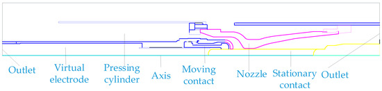
Figure 1.
Geometric model of a 252 kV circuit breaker.
The boundary conditions for the conservation equation of fluid and the turbulence control equation are fully applicable in the axisymmetric structure. The specified boundary conditions are as follows:
- (1)
- Symmetric boundary: the symmetry axis of the circuit breaker is set to the axis.
- (2)
- Pressure outlet: the circuit breaker has a pressure outlet, the pressure at the pressure outlet is set to the base pressure, the temperature is set to 293 K.
- (3)
- Solid boundary: calculate the heat flux at the solid boundary around the region where the heat is 0.
- (4)
- Dynamic mesh: in order to simplify the calculation, the method of moving static contacts is adopted.
- (5)
- Except for velocity: the radial component of the independent variable of the governing equation is set to 0.
- (6)
- User-defined scalar (UDS) to solve the current continuity equation: the end of the virtual electrode is set as the current density boundary, and the end of the static contact is zero potential.
In this study, Ansys Fluent 19.1 software is used for the calculations and C language is used for programming. The calculation flowchart is shown in Figure 2.
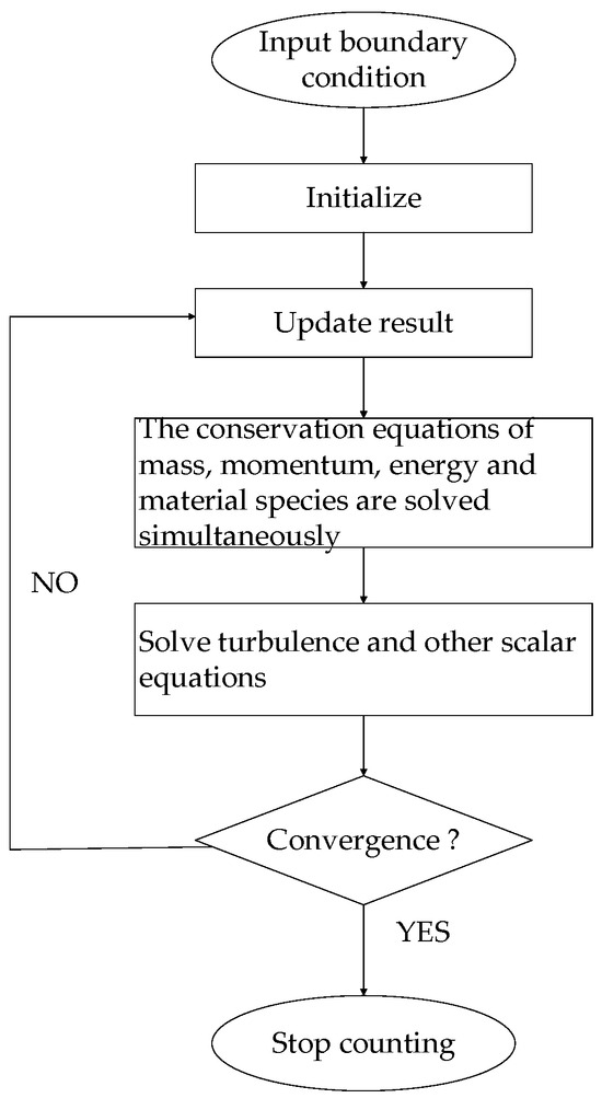
Figure 2.
Calculation flowchart.
Refer to the academic website http://plasma-data.net (accessed on 9 March 2024) and the literature [12] for the physical property parameters of the arc plasma required for the calculation.
The accuracy of the simulation model has been verified by a 40.5 kV circuit breaker. The arc voltage obtained by the simulation is basically consistent with that measured by the experiment, so the simulation model adopted in this paper is suitable for the operating conditions of circuit breakers [26].
3. Results and Discussion
Utilizing the aforementioned simulation model, this study calculates the temperature and pressure distribution within the arc-extinguishing chamber of an environmentally friendly C4F7N mixed gas circuit breaker under short-circuit conditions, while also analyzing their influencing factors. The peak current is 56 kA, at a frequency of 50 Hz. The arc initiates at 28.5 ms, reaches its maximum at 33 ms, and lasts for a duration of 4.5 ms before crossing zero at 38 ms, resulting in a total arc duration of 9.5 ms.
3.1. Analysis of Arc Dynamic Characteristics of C4F7N Mixed Gas
During the overrange stage, the stationary and dynamic contacts remain in close proximity, preventing the generation of an arc. However, once the contacts separate, the intense field strength rapidly penetrates the gas gap, leading to the occurrence of an arc phenomenon. The temperature distribution of the arc for both pure SF6 gas and a 10%C4F7N/90%CO2 mixture is depicted in Figure 3.
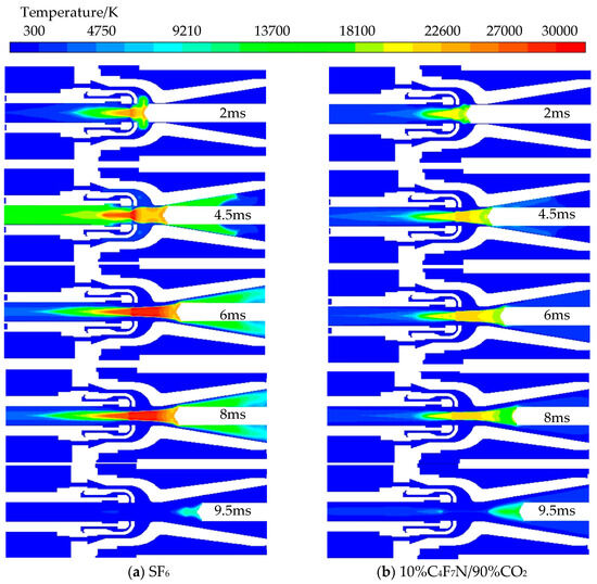
Figure 3.
Temperature distribution of quench chamber in different gases: (a) SF6, (b) 10%C4F7N/90%CO2.
At 2 ms, the large nozzle has not yet opened, and the gas flow to the right outlet is obstructed, leading to a rapid increase in the arc temperature. The core area of the arc experiences relatively high pressure as a result of the Lorentz force, leading to the radial diffusion of the arc, particularly prominent in SF6 gas. In comparison with the mixed gas, pure SF6 gas exhibits more extensive axial diffusion of high-temperature areas throughout the entire arc process.
The arc continues to develop with the movement of the contact. At 4.5 ms, when the arc burns, the current reaches its peak value, and the ohmic heat of the arc also reaches its maximum. Due to thermal inertia, energy cannot be transferred instantaneously, resulting in a lag in the change of arc temperature behind the change of current. The arc temperature does not reach its maximum at the peak current due to this lag. The incomplete opening of the large nozzle results in only a small amount of gas being blown out from the right outlet, allowing the high-temperature arc to continue heating up the gas medium in the nozzle channel. It is evident that the high-temperature area is located close to the small nozzle side, and both the arc temperature and radius are smaller for the mixed gas compared to pure SF6 gas.
At 6 ms and 8 ms, the arc morphology exhibits similarity, with the contact in motion and the arc continuously elongating. The arc temperature and radius experience a slight decrease compared to the previous peak. Notably, at this point, the arc radius of the mixed gas surpasses that of pure SF6 gas, leading to a significant amount of gas being blown towards the right outlet area. It is observed that in this region, pure SF6 gas attains a higher temperature than its counterpart. At 6 ms, the arc temperature reaches its peak value; specifically, for the mixed gas, it measures 23,000 K, significantly lower than that recorded for pure SF6 gas, at 30,000 K.
At the time of arc ignition, at 9.5 ms, the current reaches the zero-crossing point, where the input ohmic heat is minimized, and gas blowing is intensified, leading to a rapid decrease in arc temperature. The temperature of the mixed gas arc drops to 13,000 K, significantly higher than the 8000 K of pure SF6 gas. Furthermore, at the zero-crossing point, the arc area of the mixed gas is larger, and its higher extinguishing temperature results in increased conductivity. Consequently, it exhibits a lower recovery voltage compared to pure SF6 gas, thereby increasing the likelihood of reignition.
In conclusion, different gases display distinct dynamic characteristics when interrupting short-circuit currents. The pure SF6 gas arc exhibits vigorous combustion, extends further along the axis, extinguishes the arc most effectively, and is the least susceptible to re-ignition.
The flow field in the arc-extinguishing chamber effectively demonstrates the dissipation of arc energy. Prior to the full opening of the large nozzle, the pressure in the compressor cylinder continues to rise. Upon opening of the large nozzle, a significant pressure differential generates a strong airflow, facilitating the rapid dissipation of arc energy and thus promoting arc extinction. Figure 4 illustrates the pressure distribution in the arc-extinguishing chamber during the burning arcs of pure SF6 and mixed gas.
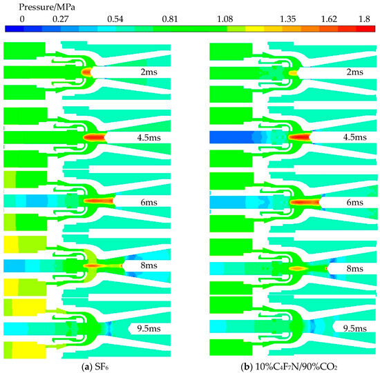
Figure 4.
Pressure distribution of quench chamber in different gases: (a) SF6, (b) 10%C4F7N/90%CO2.
After arcing, the pressure of the arc core rapidly increased, exceeding the inflating pressure significantly. When the arcing lasted for 2 ms, the pressure of the mixed gas rose to 1.3 MPa, which was 0.3 MPa lower than that of pure SF6 gas, and the high-pressure area of the arc core was smaller than that of pure SF6 gas. At this point, with the large nozzle closed, the gas pressure spread towards the virtual electrode side, resulting in a corresponding increase in pressure on the virtual arc side. When arcing continued for 4.5 ms, maximum pressure was reached in the arc core; as the contact moved, the high-pressure area gradually elongated and thinned. With arcing lasting for 6 ms and the opening of the large nozzle, a significant pressure difference formed, with the downstream outlet accelerating arc extinguishment. As arcing continued for 8 ms, the high-pressure area further narrowed; at 9.5 ms, when the current dropped to zero, the high-pressure area disappeared.
As depicted in Figure 5, the pressure curves of the two gases in the compressor cylinder exhibit distinct characteristics over time: prior to the opening of the large nozzle, the compression of the piston results in a reduction of the compressor cylinder volume, causing a slow outflow of gas from the contact gap and consequently leading to a continuous rise in pressure within the compressor cylinder. During the initial arc stage (28.5 ms), pure SF6 gas establishes a higher pressure compared to the mixed gas. Throughout the entire arc process, pure SF6 gas consistently maintains a high pressure level, with its pressure rising rate being particularly faster at the peak arc (33 ms) and approximately 0.2 MPa higher than that of the mixed gas at zero-crossing (38 ms). It is evident that different types of gases under this structure lead to varying increases in pressure. The significant compression effect observed with pure SF6 is especially conducive to generating greater pressure differences for promoting arc extinguishment, aligning with the temperature distribution, as shown in Figure 3, where pure SF6 exhibits a lower temperature and a smaller arc area at zero-crossing.
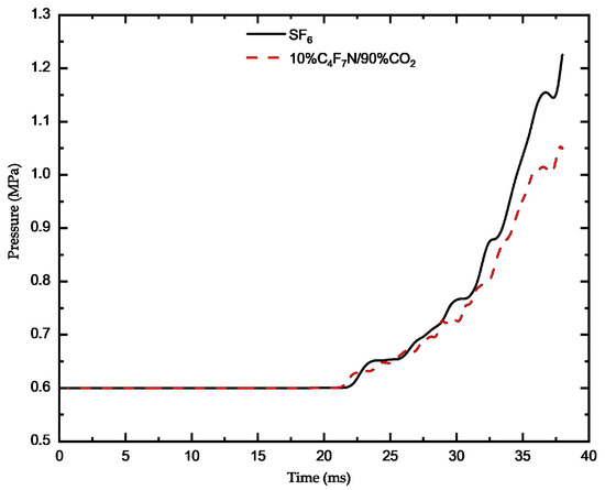
Figure 5.
Pressure curve of compressor cylinder with time.
In conclusion, during the process of arc combustion, the pressure within the high-pressure region of the arc core is lower compared to that of pure SF6 gas, and the size of this high-pressure region is also smaller. The pressure established in the compressor, both at the moment of arc combustion and extinguishment, is, likewise, lower than that of pure SF6 gas.
3.2. Influence of Inflation Pressure on Breaking Characteristics
The arc temperature distribution under 0.5 MPa, 0.6 MPa and 0.7 MPa inflation pressures is shown in Figure 6. It can be seen from the figure that the arc shape is basically the same under different inflation pressures. When the inflation pressure is 0.5 MPa, the arc temperature reaches 21,200 K at 2 ms; at 4.5 ms, the arc temperature rises to 22,600 K, increasing by 1400 K; at 9.5 ms, the arc temperature drops to 13,300 K. When the inflation pressure is 0.6 MPa, the arc temperature is 21,300 K at 2 ms; at 4.5 ms, the arc temperature rises to 22,300 K, increasing by 1000 K; at 9.5 ms, the arc temperature drops to 13,000 K. When the inflation pressure is 0.7 MPa, the arc temperature reaches 21,400 K at 2 ms; at 4.5 ms, the arc temperature rises to 21,800 K, increasing by 400 K; at 9.5 ms, the temperature drops to 12,800 K.
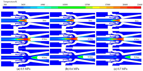
Figure 6.
Arc temperature distribution in the breaking process at different pressures: (a) 0.5 MPa, (b) 0.6 MPa, (c) 0.7 MPa.
It is evident that the higher the charging pressure, the lower the arc temperature. In the initial phase of the arc, there is a lesser impact, while the peak current and zero-crossing are more significantly affected. The temperature of the arc decreases as the charging pressure increases. At lower temperatures, the C4F7N mixed gas also demonstrates reduced conductivity, allowing it to withstand higher recovery voltages. Therefore, increasing the charging pressure can enhance the interrupting capability of the C4F7N mixed gas circuit breakers.
Under the inflating pressure of 0.5 MPa, 0.6 MPa and 0.7 MPa, the pressure distribution in the arc-extinguishing chamber is shown in Figure 7. It can be observed from the figure that, with the increase in inflating pressure, the range of high-pressure area in the arc core also expands correspondingly, and with the increase in inflating pressure, the pressure gradient at the left outlet decreases. At the time of arc ignition at 2 ms, the maximum pressure in the arc core corresponding to the three inflating pressures is 1.21 MPa, 1.33 MPa and 1.43 MPa, respectively; at the time of arc ignition at 4.5 ms, the pressure in the arc core rises to 1.55 MPa, 1.72 MPa and 1.8 MPa, increasing by 0.34 MPa, 0.39 MPa and 0.37 MPa, respectively; at the time of arc ignition at 9.5ms, the pressure in the arc core drops to 0.85 MPa, 1.05 MPa and 1.15 MPa, decreasing by 0.7 MPa, 0.72 MPa and 0.65 MPa, respectively.
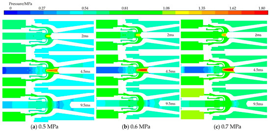
Figure 7.
Pressures distribution in the breaking process at different pressures: (a) 0.5 MPa, (b) 0.6 MPa, (c) 0.7 MPa.
It is evident that the peak pressure of the arc core increases proportionally with the increase in inflation pressure, particularly at 0.6 MPa, where the largest variation range of current peak and zero-crossing occurs. Specifically, when the inflation pressure is raised from 0.5 MPa to 0.6 MPa, the highest pressure of the arc core increases by 0.17 MPa at the moment of the current peak; and when it is increased from 0.6 MPa to 0.7 MPa, there is an increase of 0.08 MPa in the highest pressure of the arc core at the zero-crossing point as well. Therefore, selecting an inflation pressure of 0.6 MPa would be more appropriate, as further increases have little significant effect on the final result.
Under the inflation pressures of 0.5 MPa, 0.6 MPa and 0.7 MPa, the pressure inside the compressor changes with time, as shown in Figure 8.
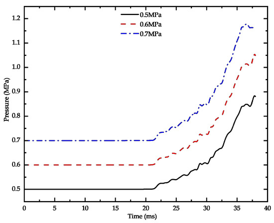
Figure 8.
Cylinder pressure at different pressures in the C4F7N/CO2 mixture.
It can be observed from the figure that the pressure changes under the three pressure conditions are consistent. At the time of the initial arc (28.5 ms), compared with the initial inflation pressure, the pressure increases by 0.08 MPa, 0.1 MPa and 1.16 MPa, respectively. At the time of arc extinguishment (38 ms), compared with the initial inflation pressure, the pressure increases by 0.38 MPa, 0.45 MPa and 0.45 MPa, respectively. Therefore, in the process of arc combustion, a higher inflation pressure will lead to a larger pressure difference and is conducive to energy dissipation. When the initial pressure increases to 0.7 MPa, compared with the 0.6 MPa inflation pressure, the increment at the time of arc extinguishment is almost the same. Therefore, it is not meaningful to further increase the inflation pressure in this case.
In conclusion, according to the comparison of temperature and pressure under different inflating pressures, it is concluded that 0.6 MPa is more appropriate.
3.3. Influence of C4F7N Proportion on Breaking Characteristics
The temperature distribution of the mixed gas with 10% and 15% of C4F7N content under short-circuit current is illustrated in Figure 9. It can be observed from the figure that at an arc duration of 2 ms, the temperatures are 21,300 K and 21,500 K, respectively, with similar arc shapes for both mixtures; at an arc duration of 4.5 ms, the temperatures increase to 22,700 K and 22,200 K, respectively, with the mixed gas containing 10%C4F7N90%CO2 exhibiting a longer and more axial spread arc, while the mixed gas containing 15%C4F7N85%CO2 has a larger radius and higher temperature blowing towards the right outlet; when the arc lasts for 9.5 ms, the temperatures decrease to 13,100 K and 13,400 K, respectively, with a longer arc shape observed for the mixed gas containing 15%C4F7N85%CO2.
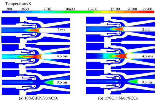
Figure 9.
Temperature distribution under different C4F7N proportions: (a) 10%C4F7N/90%CO2, (b) 15%C4F7N/85%CO2.
The temperature characteristics of the two gas mixtures vary at different stages of the arc: the mixture containing 10%C4F7N90%CO2 exhibits higher temperatures at the peak current, whereas the mixture with 15%C4F7N85%CO2 shows higher temperatures at the beginning of the arc and during the zero-current stage. The presence of a higher concentration of C4F7N leads to an increase in the extinguishing temperature during the zero-current stage. Therefore, it is more appropriate to choose a gas consisting of 10%C4F7N/90%CO2.
Figure 10 shows the pressure distribution of the mixture gas with 10% and 15% C4F7N content under short-circuit current. It can be observed from the figure that at 2 ms, the pressures of the two mixtures are 1.33 MPa and 1.44 MPa, respectively. Among these, the mixture gas with 15%C4F7N85%CO2 content presents a larger area of high-pressure and a higher pressure at the arc. At 4.5 ms, the pressures of the two mixtures are increased to 1.64 MPa and 2.11 MPa, respectively, being 0.31 MPa and 0.67 MPa higher than those at 2 ms. In addition, the area of the higher core of the mixture gas with 15%C4F7N85%CO2 content is much larger than that of the mixture gas with 10%C4F7N90%CO2 content. At 9.5 ms, the pressures of the two mixtures decrease to 1 MPa and 1.24 MPa, respectively. Therefore, it can be seen that the mixture gas with 15%C4F7N85%CO2 has a larger arc core pressure and arc core area, and the pressure gradient at the arc passage is also larger.
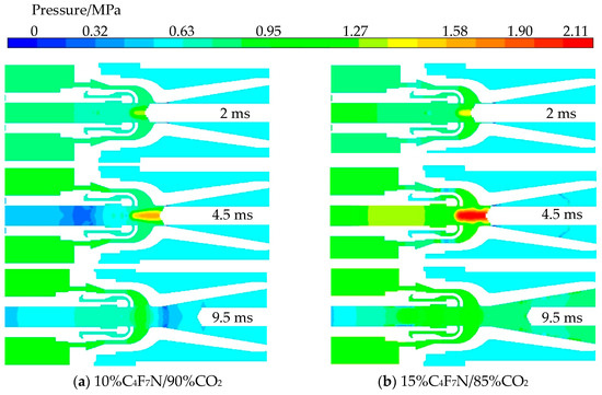
Figure 10.
Pressure distribution under different C4F7N proportions: (a) 10%C4F7N/90%CO2, (b) 15%C4F7N/85%CO2.
According to Figure 11, the influence of different C4F7N proportions on the pressure distribution in the compressor can be concluded as follows: at the moment of arcing, the pressure of the mixture gas with the 10%C4F7N/90%CO2 proportion is 0.7 MPa, which is lower than 0.71 MPa when 15%C4F7N/85%CO2 is added; when the current crosses zero, the pressure of the mixture gas with 10%C4F7N/90%CO2 proportion rises to 1.05 MPa, which is lower than 1.22 MPa when 15%C4F7N/85%CO2 is added. Therefore, increasing the content of C4F7N in the arc-extinguishing chamber can establish a larger pressure difference during the arcing process.
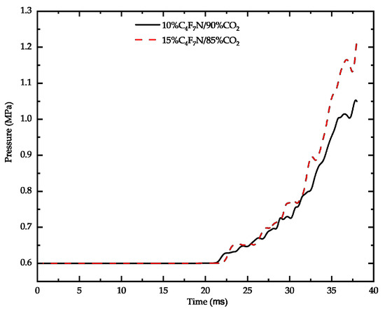
Figure 11.
Pressure of compressor cylinder with different C4F7N proportions.
Increasing the charging pressure of the mixed gas can effectively improve the breaking performance of the circuit breaker. At the same time, adjusting the proportion of the mixed gas will have an important impact on the core pressure and the pressure difference established in the compressor at the moment of arc ignition. However, this may lead to a rise in temperature when the arc is extinguished. Therefore, after comprehensive consideration, it is more appropriate to choose a 0.6 MPa charging pressure and a 10% C4F7N proportion.
In this paper, the arc characteristics of a C4F7N/CO2 mixed gas are studied, the influence of the pressure and the proportion of the mixed gas on its breaking characteristics is analyzed, and the corresponding rules are obtained. The rules and conclusions obtained in this paper are not only applicable to the structure, but also have guiding significance for other voltage levels of circuit breakers. The research method and analysis method in this paper are of guiding significance to the study of new gas breaking characteristics.
4. Conclusions
Previous studies have compared the arc voltage obtained by simulation with the arc voltage measured by experiment, and the results of the two are basically consistent, so the simulation method adopted in this study is correct. In addition, due to the similarity of the structure of the two, it is reasonable to extend the 40.5 kV circuit breaker to the 252 kV circuit breaker [26].
In this study, a model of a 252 kV compressed gas circuit breaker was developed to compare the arc characteristics of C4F7N/CO2 and SF6 gases, as well as their impact on breaking performance. The specific research conclusions are as follows:
- Under the same conditions, the arc temperature of pure SF6 gas is higher, resulting in a farther axial diffusion and a stronger arc-extinguishing effect, making it less prone to re-ignition. During the process of arc combustion, the pressure in the high-pressure region of the arc core is lower compared to that of pure SF6 gas, leading to a smaller high-pressure area. Additionally, the pressure established in the compressor at the moment of arc combustion and extinction is also lower than that of pure SF6 gas.
- The cutting performance of the mixture can be enhanced by adjusting the inflation pressure, When the aeration pressure is greater than 0.6 MPa, improving the air pressure effect has little significance, with 0.6 MPa being identified as an optimal inflation pressure.
- Following an increase in the proportion of C4F7N, there is a rise in arc temperature during ignition and extinction, but a decrease when the current peak is reached. Moreover, there is a significant increase in the core pressure after elevating the proportion of C4F7N, leading to a greater pressure difference established by the compressor chamber. Nevertheless, due to minimal change in extinguishment temperature, a 10% proportion of C4F7N remains an appropriate choice.
- In this paper, a two-dimensional axisymmetric structure is used for calculation, which may be slightly different from the actual three-dimensional structure. In this study, the simulation method is used to conduct research. Subsequent experiments need to be conducted to explore the breaking characteristics of the C4F7N/CO2 mixture.
Author Contributions
X.L. Conceptualization, investigation, writing—original draft and funding acquisition: L.L. Software, validation, data curation and visualization: W.W. Resources, project administration and supervision: Z.G. All authors have read and agreed to the published version of the manuscript.
Funding
This research was funded by the Open Fund of State Key Laboratory of Power Grid Environmental Protection (No. GYW51202301431).
Data Availability Statement
Data are contained within the article.
Conflicts of Interest
The authors declare no conflicts of interest.
Correction Statement
This article has been republished with a minor correction to the affiliation information. This change does not affect the scientific content of the article.
References
- Götte, N.; Krampert, T.; Nikolic, P.G. Series connection of gas and vacuum circuit breakers as a hybrid circuit breaker in high-voltage applications. IEEE Trans. Plasma Sci. 2020, 48, 2577–2584. [Google Scholar] [CrossRef]
- Gui, Z.W.; Li, Y. Challenges and proposals on SF6 emission reduction approaches. Sci. Total Environ. 2024, 906, 167347. [Google Scholar]
- Loizou, L.; Han, Q.; Chen, L.J.; Liu, Q.; Waldron, M.; Wilson, G.; Bautista, R.F. Partial discharge characteristics of C3F7CN gas mixture using the UHF method. Energies 2022, 15, 7731. [Google Scholar] [CrossRef]
- Huo, P.; Jiang, X. Study on lightning impulse insulation characteristics of C4F7N/CO2 binary gas mixture. High Volt. Appar. 2021, 57, 1–5. [Google Scholar]
- Owens, J.; Xiao, A. Recent development of two alternative gases to SF6 for high voltage electrical power applications. Energies 2021, 14, 5051. [Google Scholar] [CrossRef]
- Zebouchi, N.; Li, H.L.; Haddad, M.A. Development of Future compact and eco-friendly HVDC gas-insulated systems: Shape optimization of a DC spacer model and novel materials investigation. Energies 2020, 13, 3288. [Google Scholar] [CrossRef]
- Narayanan, V.R.; Gnybida, M.; Rümpler, C. Transport and radiation properties of C4F7N-CO2 gas mixtures with added oxygen. J. Phys. D Appl. Phys. 2022, 55, 295502. [Google Scholar] [CrossRef]
- Yang, Y.; Gao, K.L. Review of the decomposition characteristics of eco-friendly insulation gas. High Volt. 2021, 6, 733–749. [Google Scholar] [CrossRef]
- Carles, A.; Schlernitzauer, A.; Vignes, M.; Cros, G.; Magous, R.; Maurice, T.; Oiry, C. Heptafluoroisobutyronitrile (C4F7N), a gas used for insulating and arc quenching in electrical switchgear, is neurotoxic in the mouse brain. Toxicology 2022, 480, 153319. [Google Scholar] [CrossRef]
- Zhang, B.Y.; Hao, M. Determination and assessment of a complete and self-consistent electron-neutral collision cross-section set for the C4F7N molecule. J. Phys. D Appl. Phys. 2023, 56, 134001. [Google Scholar] [CrossRef]
- Ovad, T.; Sapunar, M. Excitation and fragmentation of the dielectric gas C4F7N: Electrons vs photons. J. Phys. D Appl. Phys. 2023, 158, 014303. [Google Scholar] [CrossRef] [PubMed]
- Zhang, Z.; Lin, X. Calculation of thermodynamic physical parameters of C4F7N/CO2 and C4F7N/N2 gas mixtures. High Volt Eng. 2020, 46, 250–256. [Google Scholar]
- Li, W.; Zhang, X.X. Research and application progress of environmental protection insulating gas C4F7N Part II: Material compatibility, safety and equipment developmen. Trans. China Electrotech. Soc. 2021, 36, 4567–4579. [Google Scholar]
- Chachereau, A.; Hsl, A. Electrical insulation properties of the perfluoronitrile C4F7N. J. Phys. D Appl. Phys. 2018, 51, 495201. [Google Scholar] [CrossRef]
- Zhang, X.X.; Chen, Q. Experimental study on power frequency breakdown characteristics of C4F7N/CO2 gas mixture under quasi-homogeneous electric field. IEEE Access 2019, 7, 19100–19108. [Google Scholar] [CrossRef]
- Xiong, J.Y.; Zhang, B.Y. Study on measurements of swarm parameters in SF6 alternative gases by pulsed townsend method. Proc. CSEE 2021, 41, 759–769. [Google Scholar]
- Zhang, T.; Zhou, W.; Zheng, Y.; Yu, J.H. Insulation properties of C4F7N/CO2 mixtures under non-uniform electric field. IEEE Trans. Dielectr. Electr. Insul. 2019, 26, 1747–1754. [Google Scholar] [CrossRef]
- Zhang, T.; Zhou, W.; Yu, J.H.; Yu, Z.X. Insulation properties of C4F7N/CO2 mixtures under lightning impulse. IEEE Trans. Dielectr. Electr. Insul. 2020, 27, 181–188. [Google Scholar] [CrossRef]
- Wang, C.L.; Li, J.; Cao, Y.D. Study on arc-extinguishing performance of DC C4F7N/CO2 mixed gas. Earth Environ. Sci. 2021, 692, 032097. [Google Scholar] [CrossRef]
- Zhu, Y.; Dong, E.Y.; Li, Z.B.; Wang, Y.X.; Zhang, Z.G.; Zhang, R.; Yan, X.L. Research on arc extinguishing performance of C4F7N/CO2 gases with slight positive pressure. IEEE Trans. Plasma Sci. 2022, 50, 410–416. [Google Scholar] [CrossRef]
- Xiao, S.; Gao, B. The sensitivity of C4F7N to electric field and its influence to environment-friendly insulating gas mixture C4F7N/CO2. J. Phys. D Appl. Phys. 2018, 54, 055501. [Google Scholar] [CrossRef]
- Seeger, M. Perspectives on research on high voltage gas circuit breakers. Plasma Chem. Plasma Process. 2015, 35, 527–541. [Google Scholar] [CrossRef]
- Bian, C.X.; He, B.N. Research on interruption performance of environmentally friendly C4F7N mixed-gas-insulated switchgear. Energies 2022, 15, 6500. [Google Scholar] [CrossRef]
- Yan, J.D.; Nuttall, K.I.; Fang, M.T.C. A comparative study of turbulence models for SF6 arcs in a supersonic nozzle. J. Phys. D Appl. Phys. 1999, 32, 1401–1406. [Google Scholar] [CrossRef]
- Dixon, C.M.; Yan, J.D.; Fang, M.T.C. A comparison of three radiation models for the calculation of nozzle arcs. J. Phys. D Appl. Phys. 2004, 37, 3309–3318. [Google Scholar] [CrossRef]
- Song, Y.; Lin, X. Interruption performance of C4F7N/CO2 gas in high-voltage circuit breaker. High Volt Eng. 2023, 49, 971–981. [Google Scholar]
Disclaimer/Publisher’s Note: The statements, opinions and data contained in all publications are solely those of the individual author(s) and contributor(s) and not of MDPI and/or the editor(s). MDPI and/or the editor(s) disclaim responsibility for any injury to people or property resulting from any ideas, methods, instructions or products referred to in the content. |
© 2024 by the authors. Licensee MDPI, Basel, Switzerland. This article is an open access article distributed under the terms and conditions of the Creative Commons Attribution (CC BY) license (https://creativecommons.org/licenses/by/4.0/).