Article

Multi-Physical Field Analysis and Optimization Design of the High-Speed Motor of an Air Compressor for Hydrogen Oxygen Fuel Cells

Fluid and Monitoring Laboratory, School of Mechanical Engineering, University of Science and Technology Beijing, Beijing 100083, China
*
Author to whom correspondence should be addressed.
Energies 2024, 17(11), 2722; https://doi.org/10.3390/en17112722
Submission received: 28 April 2024 / Revised: 28 May 2024 / Accepted: 31 May 2024 / Published: 3 June 2024
(This article belongs to the Topic Advanced Electrical Machine Design and Optimization Ⅱ)

Abstract

:
The hydrogen oxygen fuel cell is a power source with significant potential for development. The air compressor provides ample oxygen for the fuel cell, and as a key component of the air compressor, the performance of the motor greatly impacts the efficiency of the fuel cell. In order to enhance the system performance of high-speed permanent magnet motors, optimization was conducted on the motor’s geometric dimensions to minimize rotor loss and maximize power density, taking into account the comprehensive constraints of electromagnetic and mechanical properties. The finite-element method was employed to analyze the motor’s performance, conducting a multi-physical field analysis that included electromagnetic field, rotor loss, and mechanical strength analysis, as well as temperature field analysis. Aiming at the problem of high temperature rise in high-speed motor winding, the influence of the cooling water flow rate on the winding temperature rise was analyzed and simulated. Based on the analysis results, the minimum cooling water flow rate was obtained. According to the optimized design results, a prototype of an 18 kW, 100,000 rpm motor was manufactured, and the efficiency and temperature rise were tested. The experimental results verify the correctness and effectiveness of the optimal design.

1. Introduction

With the development of modern industry, high-speed permanent magnet motors are applied in more and more areas including flywheels, control moment gyroscopes in aircraft fields [1,2], and robots [3], air conditioning compressors [4], computer numerical control machine tools, and high-speed centrifugal equipment in the industrial field [5,6]. As the motor works at high speed, some factors that have a small influence on the low-speed motor must be considered in the design of the high-speed motor, for example, electromagnetic loss, rotor strength, and dynamics [7,8].
Due to the increase in pollution, the rapid depletion of oil, and energy security issues, decarbonization has been a global trend. The hydrogen fuel cell is a power generation device that directly converts the chemical energy of hydrogen and oxygen into electrical energy. The intermittent nature of most renewable energy sources creates a spatial and temporal gap between energy availability and end-user consumption. To address these challenges, an increasing number of scholars are focusing on the development of grid-compatible energy conversion and storage systems, such as the integration of hydrogen production through water electrolysis with fuel cell technology [9]. Simultaneously, cost reduction is also a crucial factor for fuel cells [10]. With further cost reduction and further performance improvement, in the foreseeable future, fuel cells are poised to become one of the primary power sources for the new energy vehicle industry [11,12]. In order to increase the oxygen electrode pressure and improve the reaction speed, the air compressor is usually used to provide a sufficient oxygen source for the fuel cell. Therefore, the performance of the air compressor directly determines the working performance of the fuel cell. As a key equipment of an air compressor, the performance of the motor greatly affects the efficiency of the fuel cell.
The performance analysis and design optimization of high-speed motors has been a continuous research hotspot in recent years, which has attracted the attention of many scholars and engineers. Motor performance can not only be optimized from the overall system level [13,14], but also focus on a specific performance [15,16]. In the literature [17], different from the general optimization at the component level, the robustness of the motor is optimized based on the six-sigma method considering manufacturing quality. The internal magnetic field of a high-speed motor changes frequently, which will cause a large electromagnetic loss. At the same time, the rotor surface will also produce wind wear. Therefore, in addition to robustness, loss analysis and minimization are also the focus of high-speed motor design optimization. The loss of a high-speed rotating machine is analyzed and calculated by the finite-element method in reference [18,19]. Loss analysis and thermal analysis are usually conducted together. Considering the loss as the thermal source, the temperature field was analyzed with FEM [20]. The mechanical performance research of the motor body mainly focuses on the new structure design, the rigidity, and mechanical loss of the rotor assembly [21,22]. The mechanical loss of a high-speed permanent magnet motor was calculated by a combination of the analytical method and FEM [23]. In the process of modeling and analyzing the motor based on the analytical method to realize the multi-objective optimization of the motor, researchers mostly use the weighted coefficient method to simplify the multi-objective problem into a single-objective problem to simplify the optimization process [24]. In the optimization of high-speed permanent magnet motors, much of the literature focuses on a single aspect of electromagnetism or mechanics. However, considering the influence of motor geometry on the electromagnetic and mechanical properties is the direction for optimizing high-speed motor design [25]. For high-speed motors used in fuel cells, controlling the temperature rise is crucial not only to ensure motor performance but also for safety considerations.
This paper focuses on the design optimization and multi-physics analysis of a high-speed motor of an air compressor for a hydrogen oxygen fuel cell. Firstly, the structure of a high-speed permanent magnet motor with water bearing support and water cooling is introduced. Secondly, the size optimization of the high-speed motor is carried out with the minimum rotor loss and maximization of power density as the objective and the main electromagnetic and mechanical properties of the motor as constraints. Thirdly, a multi-physical field analysis of the high-speed permanent magnet motor is conducted, including electromagnetic field analysis, rotor loss, and mechanical strength analysis. Fourthly, the temperature field and the influence of cooling water flow rate on winding temperature rise is analyzed and simulated. The minimum cooling water flow rate is obtained. Finally, based on the optimized design results, the prototype was produced, and the performance test data were given.

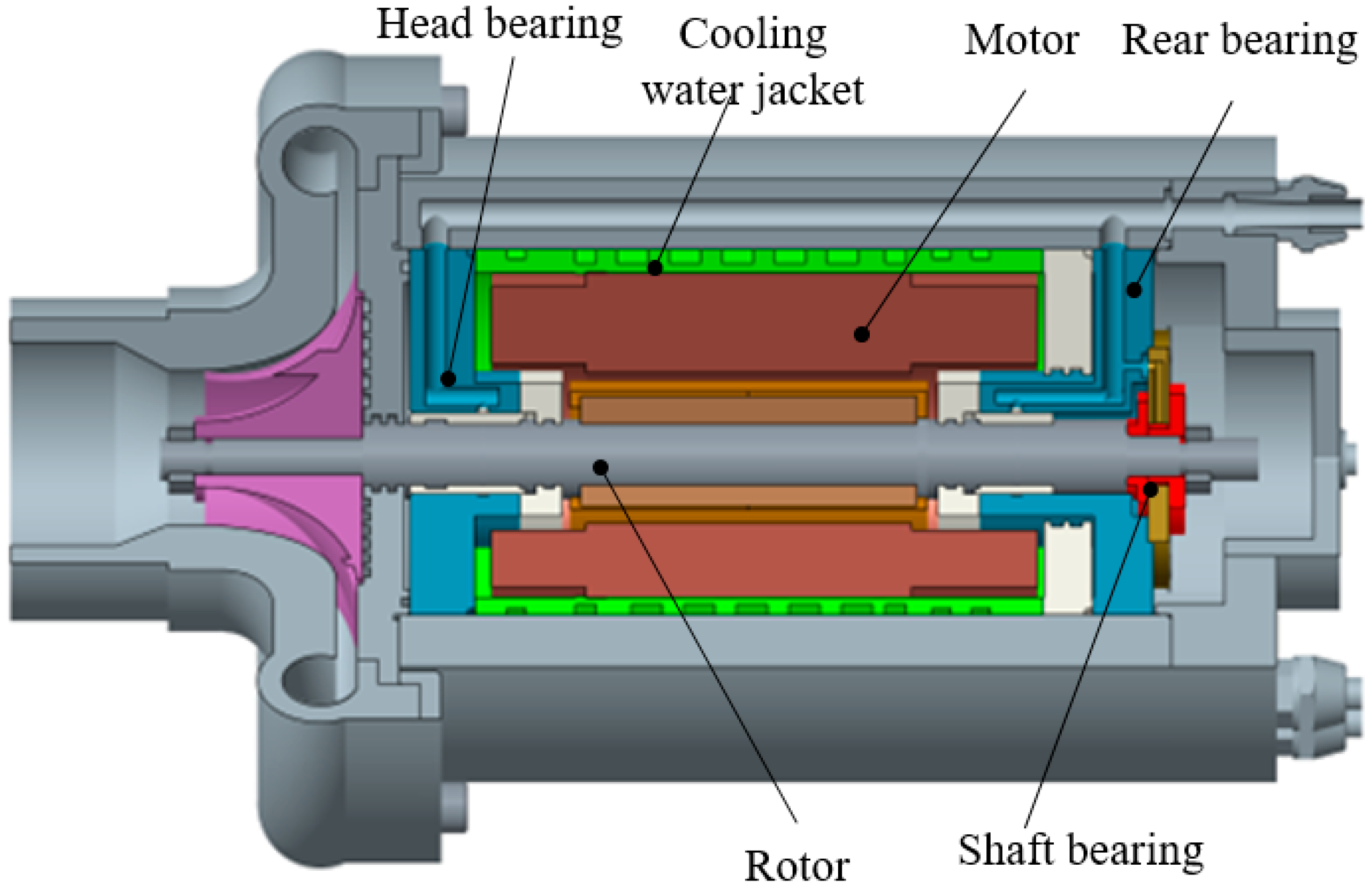
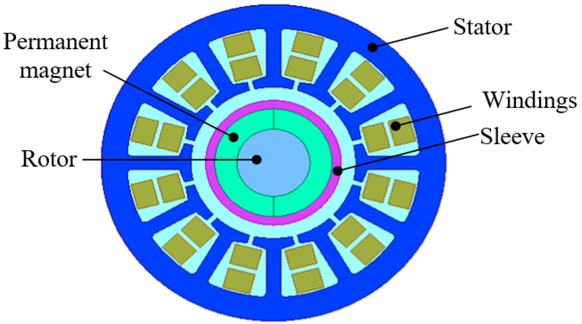
2. Motor Structure of Air Compressor

A high-speed permanent magnet synchronous motor in this paper is designed for an air compressor of a hydrogen oxygen fuel cell. The horizontal arrangement of this machine is shown in Figure 1. To minimize friction loss on the bearing, the rotor is supported by a water-lubricated bearing, with a thrust bearing positioned at the rear end. Compared with mechanical bearings, water bearings can not only realize the non-contact support of the rotor, but can also cool the bearing. Compared to other non-contact supports, such as magnetic bearings, water bearings are low-cost and simple to achieve without the need for additional controllers. Therefore, water bearings have become one of the best ways to support high-speed motors. Additionally, to prevent the overheating of the high-speed motor, a cooling water jacket is arranged outside the motor stator to facilitate the water cooling of the machine. Furthermore, provision has been made for motor wiring within the equipment shell to accommodate space for wiring of the motor controller.
The axial cross-section of the high-speed PMSM is illustrated in Figure 2. In the case of a high-speed PMSM, an increase in pole pairs leads to a rapid rise in stator loss due to the high rotational speed, which may result in unacceptable heat generation. Therefore, the high-speed motor in this design adopts a one-pair pole structure, and the permanent magnet can adopt an integral structure. This motor structure offers advantages such as a low alternating frequency of magnetic field, low stator iron loss, and ease of processing. To prevent damage to the permanent magnet from centrifugal force at high speeds, a protective sleeve covers the outer part of the magnetic steel with an interference fit between them. The stator utilizes a 12-slot structure and is made using 20WTG1500 (laminated) material to reduce eddy-current effects. The winding connection mode is a double-layer short-distance star connection in order to minimize the influence of the skin effect by winding each turn in parallel with multiple strands.

3. Optimization of Motor Performance

Multi-physical field analysis is characterized by a high accuracy and no need for experiment and empirical correction coefficients. However, the objective function obtained from its analysis results is discontinuous and difficult to derive, so a specific optimization algorithm is required.

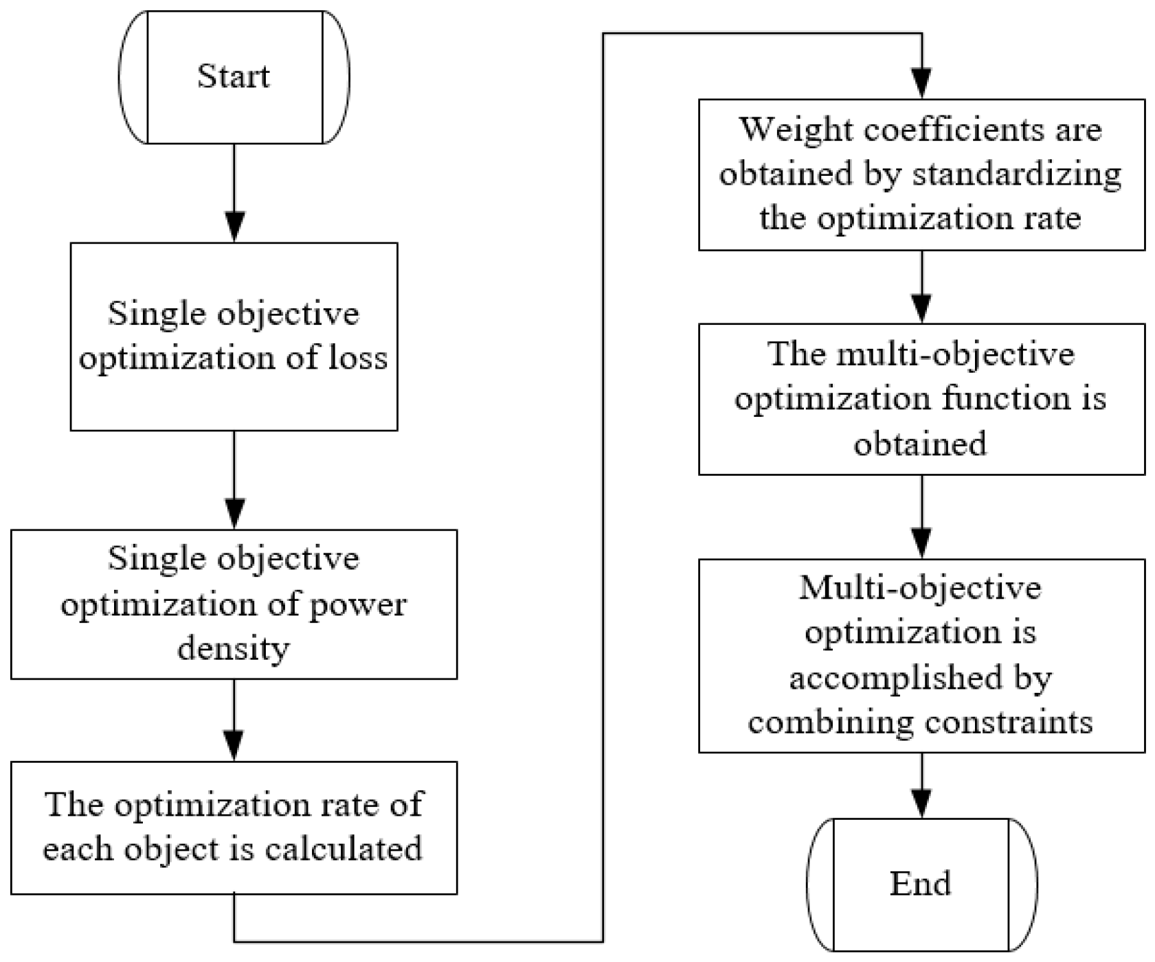
3.1. Optimization Algorithm

The Sequential Quadratic Programming (SQP) algorithm is utilized for solving constrained nonlinear optimization problems. It does not require the derivation of the objective function; instead, it directly utilizes the values of the objective function and constraint function for optimization. This algorithm is known for its stability and quick convergence [26,27]. The optimization of high-speed PMSM involves nonlinear optimization with constrained conditions.

3.2. Optimization Objectives and Design Variables

The selection of design variables has a significant impact on the optimization results. The improper selection of design variables can lead to unacceptable output or require additional iterations. In this paper, the main objective of optimization is to minimize rotor loss with a large weight coefficient. The secondary objective of optimization is to obtain the maximum energy density with a small weight coefficient. The geometric dimension that has a major impact on rotor loss is selected as the design variable for optimization.

3.2.1. Design Variables

The design variables are listed in Table 1, which includes the outer diameter of the rotor permanent magnet, thickness of the rotor sheath, mechanical air gap of the motor, outer diameter of motor stator, and axial length of motor. The value range for each optimization variable is provided in Table 1.
The optimization vector X P formed by all design variables was expressed as follows
X P = d 0 d 1 d 2 l s l e l g a p l a x

3.2.2. Optimization Objectives

The loss of motor rotor L s r e d d y mainly consists of eddy current loss and wind loss. Eddy current loss can be calculated based on the equation below.
L s r e d d y = 1 σ v o l J e d 2 d v
where σ is the conductivity of the rotor material; J e d represents the eddy current density.
The wind loss L s r w i n d can be calculated as follows.
L s r w i n d = k r o g C f ρ π ω 3 r o 4 l 2
where k r o g denotes the roughness coefficient of the surface; C f denotes the friction coefficient; ρ denotes the density of air; ω denotes the angular velocity of the rotor; l 2 is the length of the cylinder; r o denotes the outer radius of the rotor component, expressed by design variables as
r 0 = d 1 2 + l s l e
where l s l e is the radial thickness of the rotor sleeve; d 1 is the inner diameter of PM.
The minimum rotor loss is the main objective function of the optimal design, and its mathematical description is
min L r o t o r = L s r e d d y + L s r w i n d
where L s r e d d y represents the eddy current loss of rotor; and L s r w i n d represents the wind loss.
The power density of a high-speed motor is defined as the output power divided by the total mass of the motor. It can be expressed as
ρ p o w e r = P m s t a t o r + m r o t o r + m w i n d i n g
where P is the motor’s output power; m s t a t o r , m r o t o r , and m w i n d i n g represent the mass of the stator, rotor, and winding components, respectively. They can be calculated as
m s t a t o r = ρ s t e e l π d 2 2 4 π d 1 2 + l s l e + l g a p 2 n s l o t A s l o t l a x i m r o c o m p = ρ s t e e l π 4 d 1 2 l a x i + ρ p m π 4 d 0 2 d 1 2 l a x i + ρ s l e π d 0 2 + l s l e 2 d 0 2 2 l a x i m w i n d i n g = ρ c u k s l o t n s l o t A s l o t l a x i
where ρ s t e e l and ρ c u represent the density of silicon steel laminates and copper, respectively; ρ p m and ρ s l e represent the densities of the permanent magnet and the sheath material, respectively; n s l o t and A s l o t represent the number and cross-sectional area of the stator slots, respectively; and k s l o t represents the stator slot filling rate.
The optimization process is shown in Figure 3.
Power density maximization is the second optimization objective. Maximizing the power density is equivalent to minimizing its reciprocal. If each target is assigned a weight coefficient separately, the final objective function is expressed as
min F o p t = w 1 L r o t o r + w 2 1 ρ p o w e r
where w 1 and w 2 represent the weight coefficients of two objectives, separately. As shown in Figure 3, in order to obtain a reasonable multi-objective optimization function, we first calculate the optimization rate of the single objective function on the basis of the single objective optimization. The optimization rate of the single objective function can be calculated by the following expression
r i = f i f i f i
where r i is the optimization rate of each target; f i is the initial value of the objective; and f i is the optimal value of the single objective optimization, i = 1, 2. Weight coefficients can be obtained by standardizing the optimization rate as follows.
w i = r i i = 1 2 r i
Finally, based on Equation (10), the two weight coefficients are set as
w = w 1 w 2 = 0.8 0.2
According to specific motor performance requirements, there are other constraints in the process of optimization design.
(1)
Output power constraints
The motor’s output power must not be less than 18 kW.
P = T e ω 18   kW
where T e represents the output torque.
(2)
Current constraints
The current in the motor stator armature must not exceed a certain limit, as it may lead to overheating and damage to the insulation layer. Therefore, the phase current during optimization design needs to satisfy specific conditions.
I P 90   A
(3)
Stiffness constraint
In order to ensure the stable operation of a high-speed motor, it is necessary for the rotor to operate in a rigid state. The natural frequency should be at least 1.43 times greater than the operating speed frequency of the rotor. The axial length of the design variable is directly related to the first critical speed of the rotor.
(4)
Strength constraint
In order to ensure the safety of the rotor sheath and permanent magnet at high speeds, our design incorporates a safety factor greater than 2. Therefore, the maximum equivalent stress of the rotor sleeve at the rated speed should be less than half of the allowable stress. It is essential that the sleeve and permanent magnet are always in contact, ensuring that the contact stress between them remains greater than zero.

3.3. Optimization Results

The optimized motor parameters are shown in Table 2.

4. Multi Physical Field Analysis of Motor

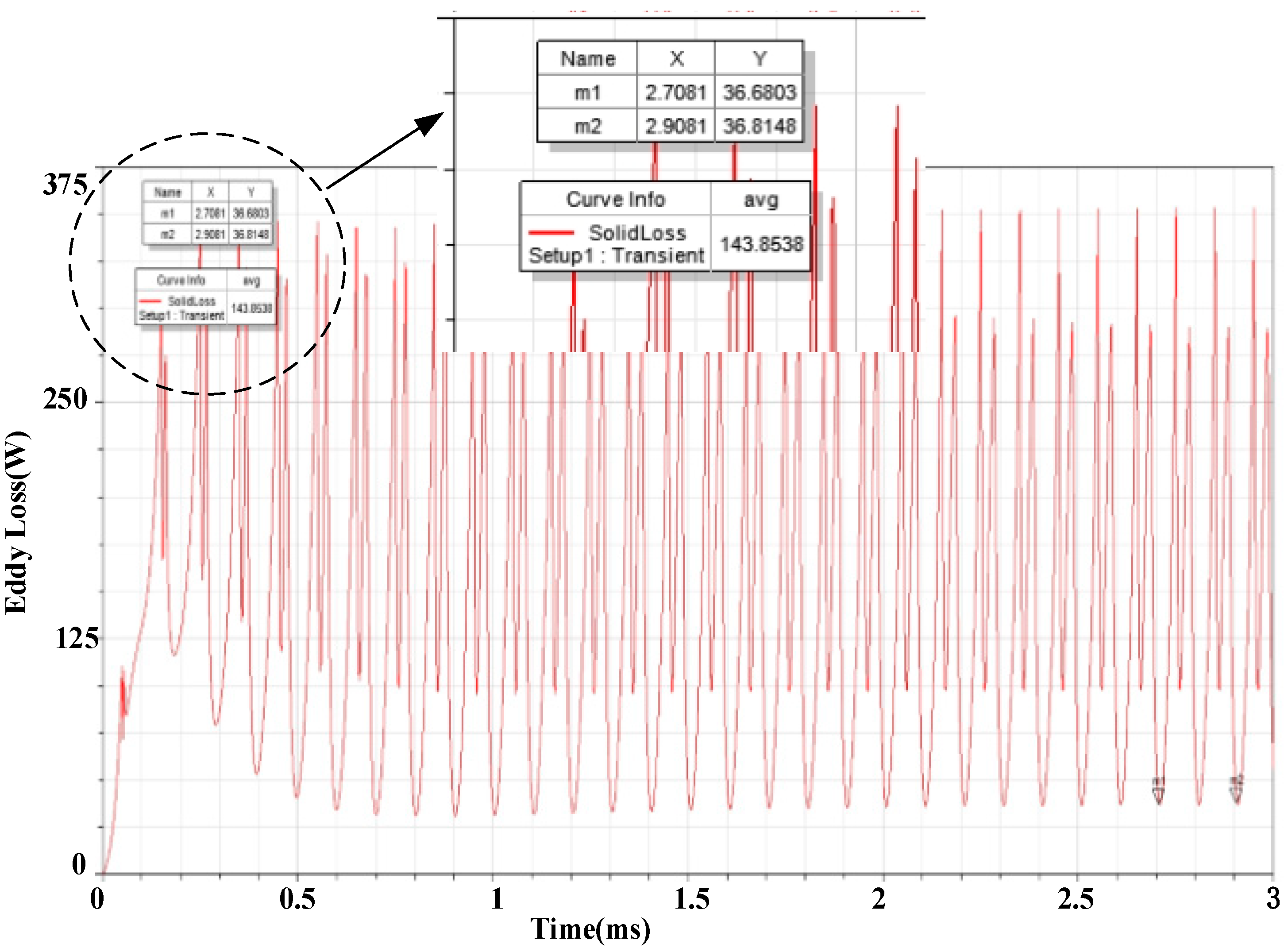
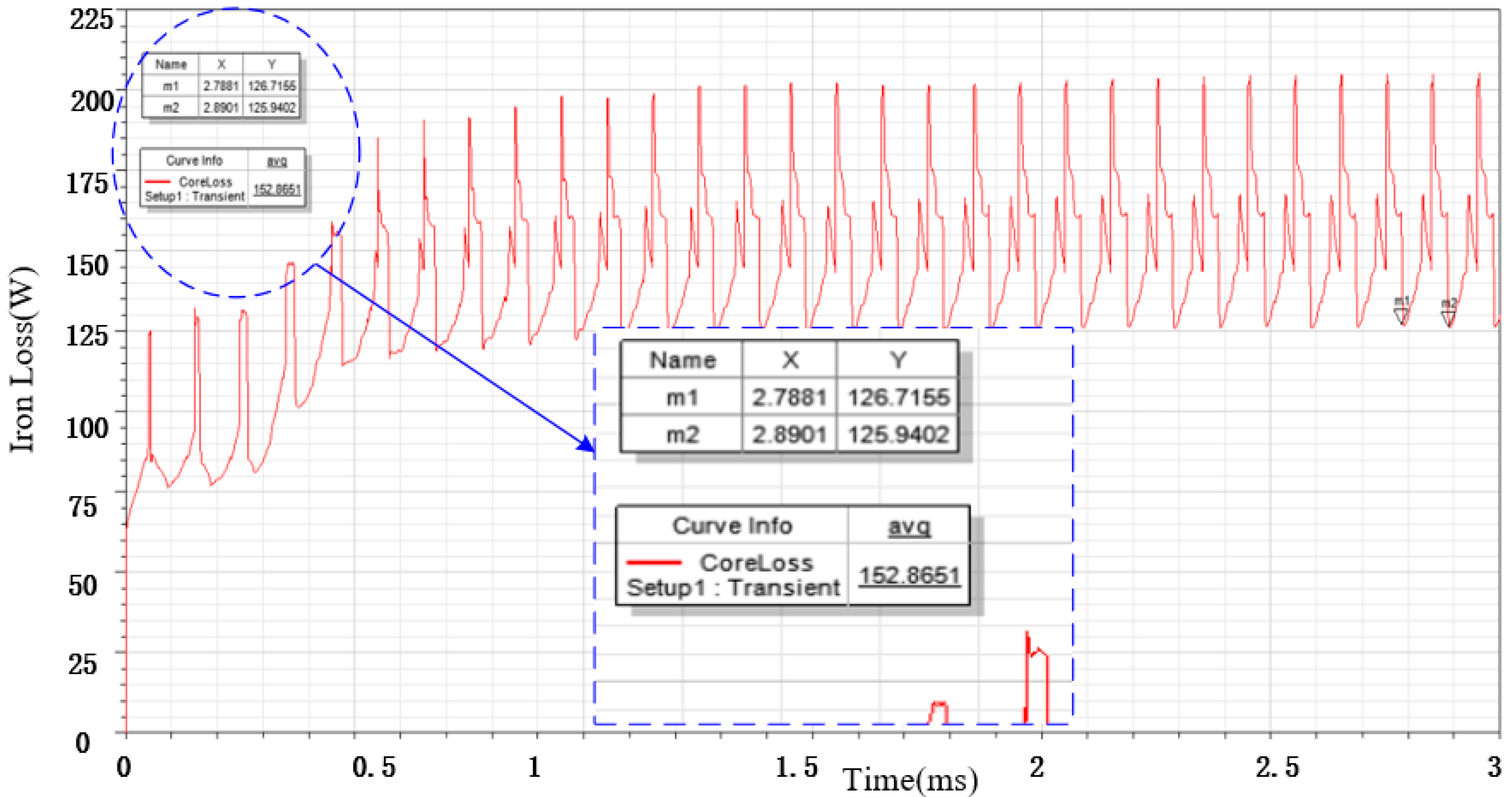
4.1. Calculation of Loss

The eddy current loss in the rotor of a high-speed motor is the primary factor contributing to rotor heating. Influencing factors include the spatial and temporal harmonics of magnetic flux, as well as stator slot openings. Due to the typically large air gap in high-speed motors, the impact of spatial harmonics is generally minimal.
Based on the fundamental principle of electromagnetic field, the governing equations of the eddy current region can be derived in terms of the vector magnetic potential A and scalar potential ϕ as follows.
× ν · × A = γ ϕ + A t · γ ϕ + A t = 0
The magnetic vector potential A of each node in the model can be calculated. Thus, the current density and eddy current loss can be obtained by FEM. The waveform of the loss at a speed of 10 krpm is depicted in Figure 4. As shown in Figure 4, the eddy current loss amounts to 143.9 W.
The computed stator iron loss results are shown in Figure 5. As shown in Figure 5, the iron loss of stator is about 152.9 W.
The simulation wave of the three phase currents is shown in Figure 6. The effective value of the phase current is 85 A, whereas the maximum value of the phase current is 160 A.
According to Figure 6 and the relative size parameters in Table 2, the winding current density J a can be calculated as
J a = 4 I r e m a N a π d 2 = 4 × 85 2 × 16 × π × 0.63 2 = 8.5   A / mm 2
where I r e m represents the effective value of the motor phase current with unit A; a represents the number of parallel branches; N a represents the number of strands in parallel; d represents the diameter of single enameled wire with unit mm; and J a stands for current density with unit A/mm2.
The copper loss heat load of the motor can be obtained according to the following equation
J c o p = 4 Z N I r e m 2 a 2 N a π 2 D i s d 2 = 4 × 12 × 10 × 85 2 2 2 × 16 × π 2 × 45 × 0.63 2 = 307   ( A 2 / mm 3 )
where Z represents the number of slots in the stator; N indicates the number of conductors per slot. Dis represents the inner diameter of the stator with unit mm; Jcop is the heat load with unit A2/mm3. Under the condition of circulating water cooling, the motor can work normally for a long time.

4.2. Stress Analysis of Rotor

The high rotor speed of a high-speed motor can generate significant tensile stress. To prevent damage from this stress when the magnetic steel rotates, an interference fit is required between the outer protective sleeve and the magnetic steel. This fit provides compressive stress for the magnetic steel, effectively counteracting the tensile stress caused by high-speed rotation and serving to protect the integrity of the magnetic steel.
The maximum tensile stress and compressive stress of the magnetic steel and sheath can be obtained from the simulation nephogram, as shown in Figure 7. When the interference is 0.05 mm, the magnetic steel produces a maximum tensile stress on the inner surface of 93.487 MPa, which is below its tensile limit of 100 MPa, meeting the operational requirements of the motor. The maximum stress of the sheath is 406.81 MPa, which is below its yield strength of 900 MPa, thus meeting the design requirements.

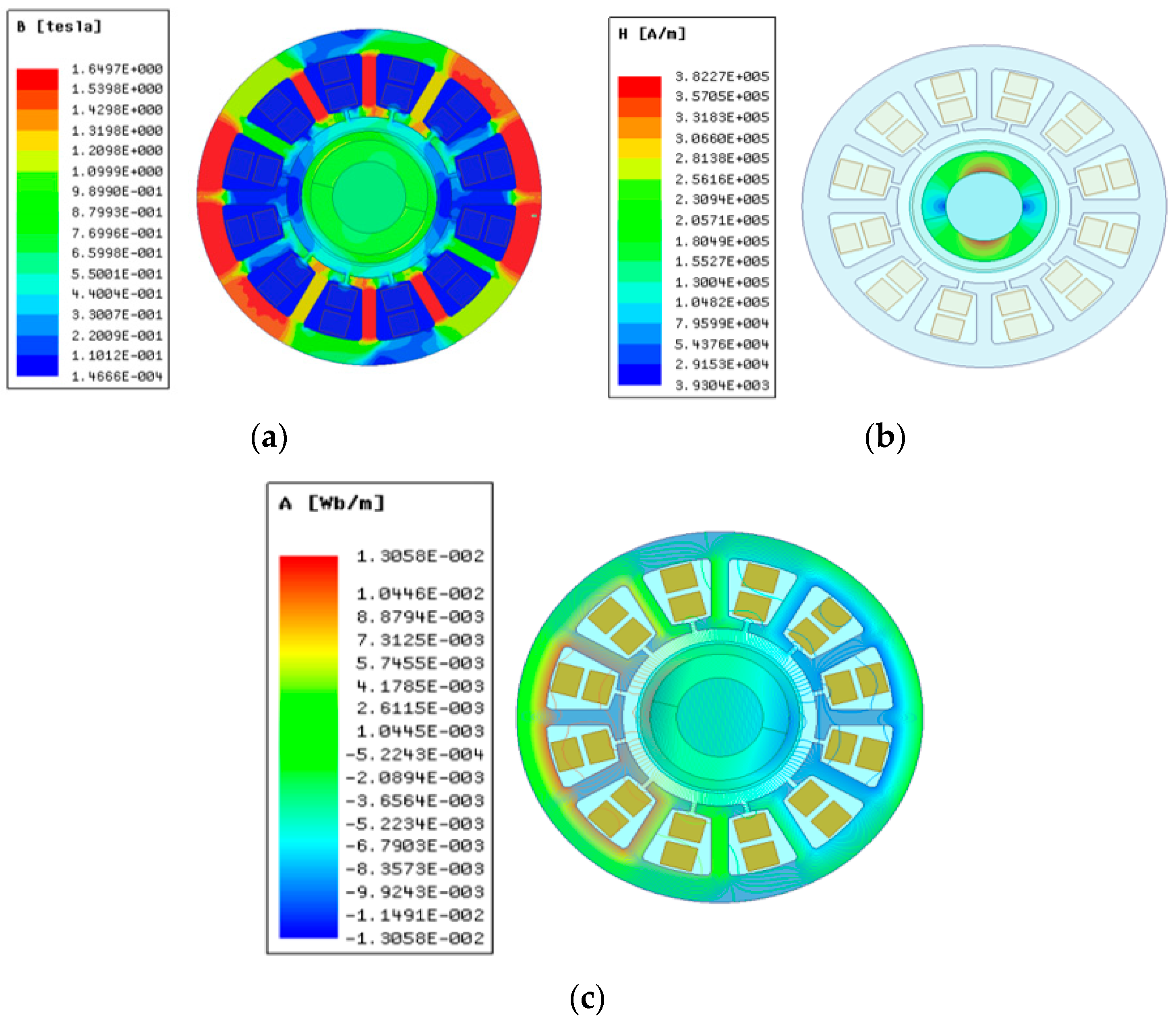
4.3. Magnetic Field Analysis

The magnetic field analysis of the motor by FEM is shown in Figure 8.
If the stator lamination remains in a state of magnetic saturation for an extended period, voltage fluctuations may lead to significant variations in current, thereby impacting motor performance and potentially causing motor burnout. The simulation of magnetic induction intensity for each part of the motor is depicted in Figure 8a as a cloud diagram. As shown in Figure 8a, the maximum magnetic induction intensity of the stator teeth is 1.6 T, while the magnetic induction intensity of the stator yoke reaches 1.65 T, neither of which exceed the magnetic saturation density of the stator lamination.
The magnetic field strength of PM is shown in Figure 8b. The maximum magnetic field strength is 382.27 KA/m, which is far less than the demagnetizing magnetic field strength of 910.5 KA/m of magnetic steel. The distribution of the magnetic field lines of the motor is shown in Figure 7c. It can be seen from Figure 8c that the distribution of the magnetic field lines is regular and the magnetic flux leakage at the end is not obvious.

5. Temperature Field and Water-Cooling Analysis

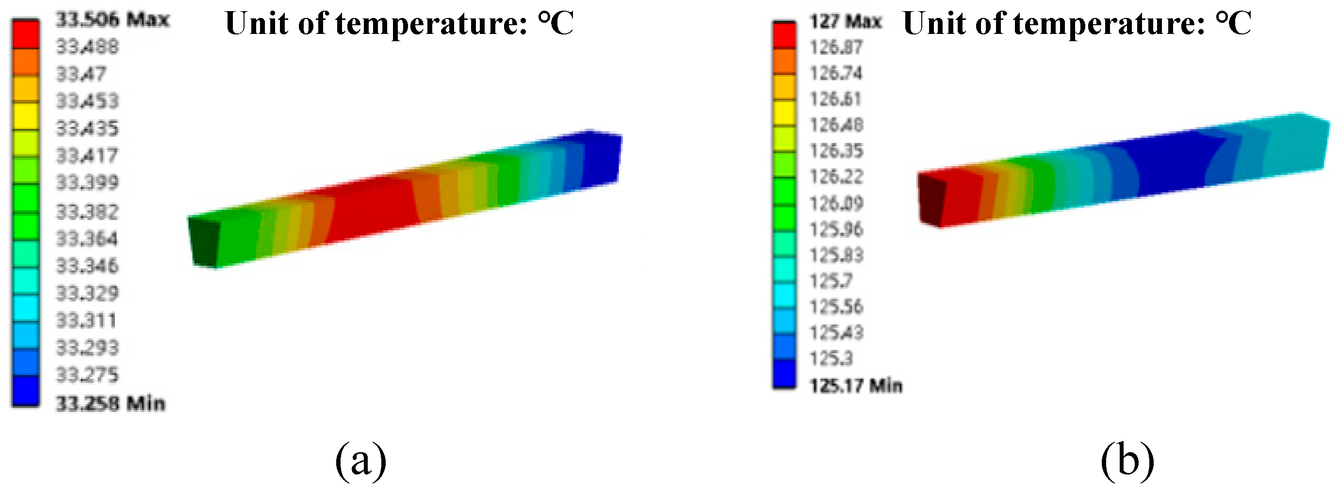
5.1. Temperature Field Analysis

During the operation of the motor, the stator iron loss, rotor eddy current loss, and winding copper loss are mainly generated, and these three losses will be converted into heat and become the heat source of the motor. During the simulation process, the three types of losses are converted into volumetric heat generation rates, facilitating the finite-element simulation calculation of the temperature distribution. The calculation results of the heat source distribution inside the motor are shown in Table 3.
The boundary conditions required for temperature calculation primarily involve defining the material properties of each motor component, specifying heat conduction between different contacting structures, determining heat convection between the outer shell surface and ambient air (e.g., end cover), and incorporating the motor’s heat source.
(1)
Determination of the heat transfer coefficient of the outer surface of the shell and the end cover. There are two kinds of heat transfer in the fluid: convection and conduction, and the heat exchange caused by these two kinds of heat transfer is called convective heat transfer. In the heating process of the motor, there is convective heat transfer between the casing and the outside air, the sheath and the air gap, and the end cover and the outside air, so it is necessary to determine the convective heat transfer coefficient of the heat exchange surface.
The convective heat transfer coefficient of the heat exchange surface can be calculated by an empirical formula [28]:
α = 1 + 0.25 ν x 0.045
where ν X is air velocity in m/s; α is the heat transfer coefficient in W / m 2 · K .
In natural convection heat transfer, the air flow rate is considered to be negligible. Consequently, the convective heat transfer coefficient between the outer surface of the casing and the end cover and the air is determined to be α = 22.22   W / m 2 · K .
(2)
Determination of the heat transfer coefficient of the outer surface of the rotor
According to the theory of fixed-rotor air-gap heat transfer, the airflow in the air gap is characterized by a combination of axial and rotational flows [28], and the Reynolds number of its effective velocity is as follows:
Re = 2 δ E ν e / ν = 2 δ E ν a 2 + ν R / 2 2 / ν
where δ E is the equivalent diameter; ν is the viscosity of air motion; ν R is the circular velocity of the outer surface of the rotor; ν a is the axial airflow speed; and Re is the Reynolds number. Here,
ν R = 194   m / s ; ν a = 9.7   m / s ; δ E = 0.0013   m ; ν = 2.109 × 10 5   m 2 / s
The Reynolds number can be calculated as Re = 120,096 . When the Reynolds number exceeds 4000, the fluid exhibits turbulent behavior. The Nusselt number can then be calculated as [29]
N u = 0.023 · Re 0.8 · P r n
where N u represents the Nusselt number; P r is the Planck number. Here, the Planck number of air at 80 degrees Celsius is 0.692, with a corresponding value of n equal to 0.3.
The relationship between the heat transfer coefficient and the Nusselt number is shown in the equation
h = λ · N u / δ E
where h is the heat transfer coefficient with unit W/(m2K); λ is the thermal conductivity; and the air thermal conductivity at 80 °C is 0.0305 W/(mK).
According to Equation (21), the heat transfer coefficient of the final air-gap fluid is calculated as h = 318.38 W/(m2K).
(3)
Determination of thermal conductivity
Heat transfer occurs when objects of different temperatures come into contact with each other. Therefore, it is essential to provide the thermodynamic properties of each part of the motor material in order to calculate the temperature field. The density, specific heat capacity, and thermal conductivity of the materials in each component of the motor are listed in Table 4.
Figure 9 illustrates the temperature distribution of the motor by the finite-element method (FEM).
It can be seen in Figure 9 that the highest temperature is located at the left end of the motor cover. This can be attributed to the fact that the left side of the motor is connected to the turbine. During the high-speed rotation of the motor, the turbine generates elevated temperatures, resulting in a corresponding increase in temperature at the left end cover of the motor. This represents the highest temperature among all parts of the motor. Specifically, it was found that the winding reached a maximum temperature of 127 °C, while magnetic steel reached a maximum temperature of 92 °C.
The temperature simulation of the motor winding at various speeds was conducted. The temperature distribution of the motor winding is depicted in Figure 10. It can be seen in Figure 10a that when the rotating speed is 20 krpm, the highest temperature of the winding occurs in the middle. This phenomenon can be attributed to the lower temperature of the spiral case at the front end of the motor when the rotating speed is low, with most heat being generated from the winding itself. The middle section of the winding is insulated equivalently, while both ends are directly exposed to air, resulting in good heat dissipation conditions. In Figure 10b, it is evident that at a rotating speed of 100 krpm, the highest temperature of the winding occurs in the front end. With the increase in the rotating speed, the temperature of the spiral case at the front end of the motor increases, resulting in the increase in the ambient temperature at the front end of the winding, so the temperature at the front end of the winding is higher.

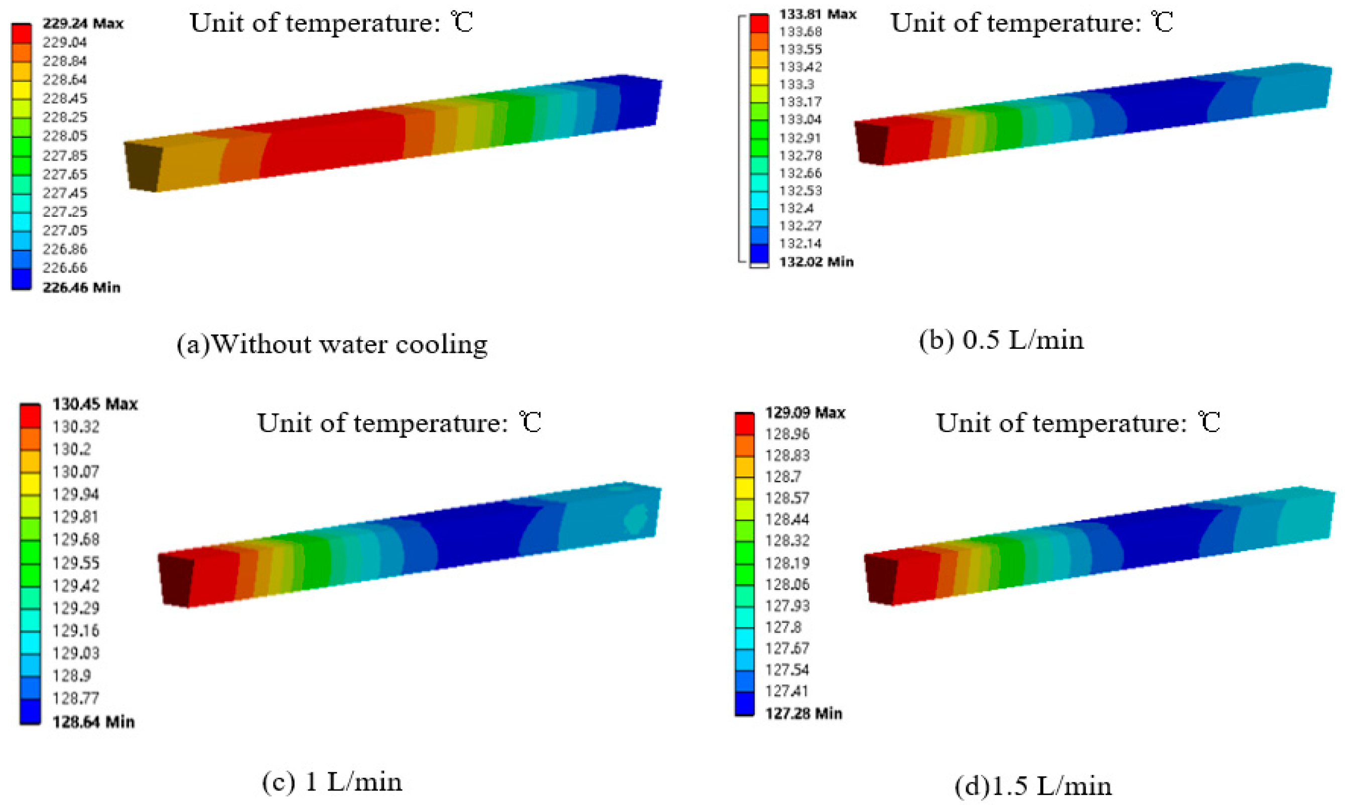
5.2. Effect of Cooling Water on Motor Temperature
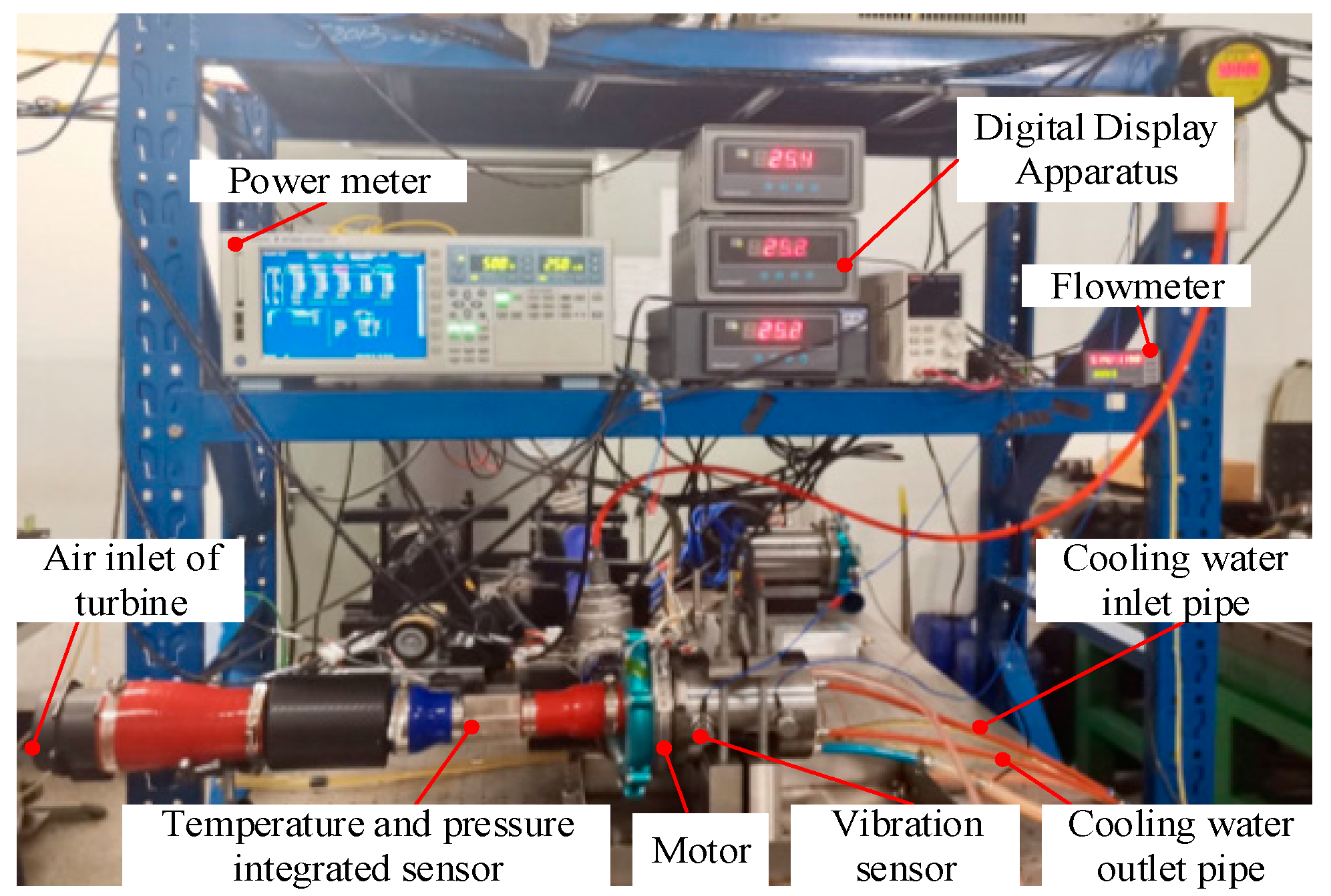
For high-speed motors, a reliable cooling system is crucial. This paper utilizes the water-cooling method. The cooling water flow was set in the range of 0~1.5 L/min to analyze its effect on the temperature of the motor winding. Temperature simulation analysis results conducted for the motor winding are presented in Figure 11. It can be seen from Figure 11a that without a water-cooling system, the motor winding temperature reaches as high as 229 °C. The temperature distribution cloud diagram of motor windings at 0.5 L/min, 1 L/min, and 1.5 L/min water flows are shown in Figure 11b, Figure 11c, and Figure 11d, respectively. It can be seen from Figure 10 that as the flow rate of cooling water increases, the cooling effect improves, and the motor winding temperature decreases. However, the decrease in motor winding temperature gradually stabilizes. From a water-free cooling system to a 0.5 L/min cooling water flow, the motor winding temperature reduces from 229 °C to 133 °C, representing a reduction of 42%. When the cooling water flow increases from 0.5 L/min to 1.5 L/min, the motor winding temperature only decreases from 133 °C to 129 °C, indicating a mere reduction of 3%. It is evident that when the cooling water flow reaches above 0.5 L/min, there is no significant decrease in the motor winding temperature. Therefore, it is essential to ensure that the water flow of the motor cooling system reaches a minimum of 0.5 L/min during operation.

6. Experiments

Temperature rise is a crucial indicator of motor performance, reflecting the loss of each component. The experimental setup for motor testing is illustrated in Figure 12 and consists of five main components: a constant voltage DC power supply cabinet, controller, water supply system, motor, and turbine. Power meters are utilized to measure the voltage, current, and power of the motor. Additionally, three temperature sensors work in conjunction with a digital display instrument to measure the temperature of the motor winding, spiral case, and bearing water. Vibration sensors monitor the vibration during motor operation, while integrated temperature and pressure sensors gauge the pressure and flow within the compressor chamber.

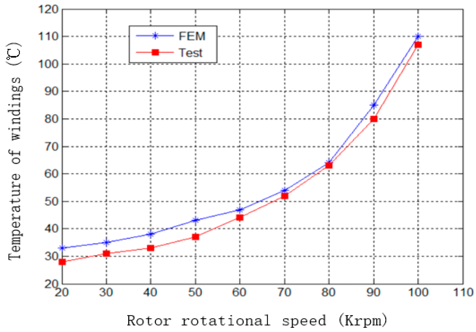
6.1. Test of Temperature Rising

The motor in this paper is developed for the air compressor of a hydrogen and oxygen fuel cell. It needs to be able to work for a long time. The ability of the motor to remain within the normal temperature range is crucial for its long-term functionality. To measure the temperature of the winding, a PT100 temperature sensor was embedded inside the winding. The test results for the winding temperature at different speeds are shown in Figure 13.
It can be seen from Figure 13 that as the speed increases, so does the temperature of the motor winding. Furthermore, higher speeds result in faster temperature rises. At a speed of 100 krpm, the maximum temperature recorded for the motor winding was 109 °C, which was lower than the temperature resistance limit of winding 180 °C. The error between the measured and simulated temperatures is greater at lower speeds but decreases as speed increases. Throughout all working speeds, both the absolute and relative errors between the design and experimental values for winding temperatures did not exceed 5 °C and 10%, respectively.

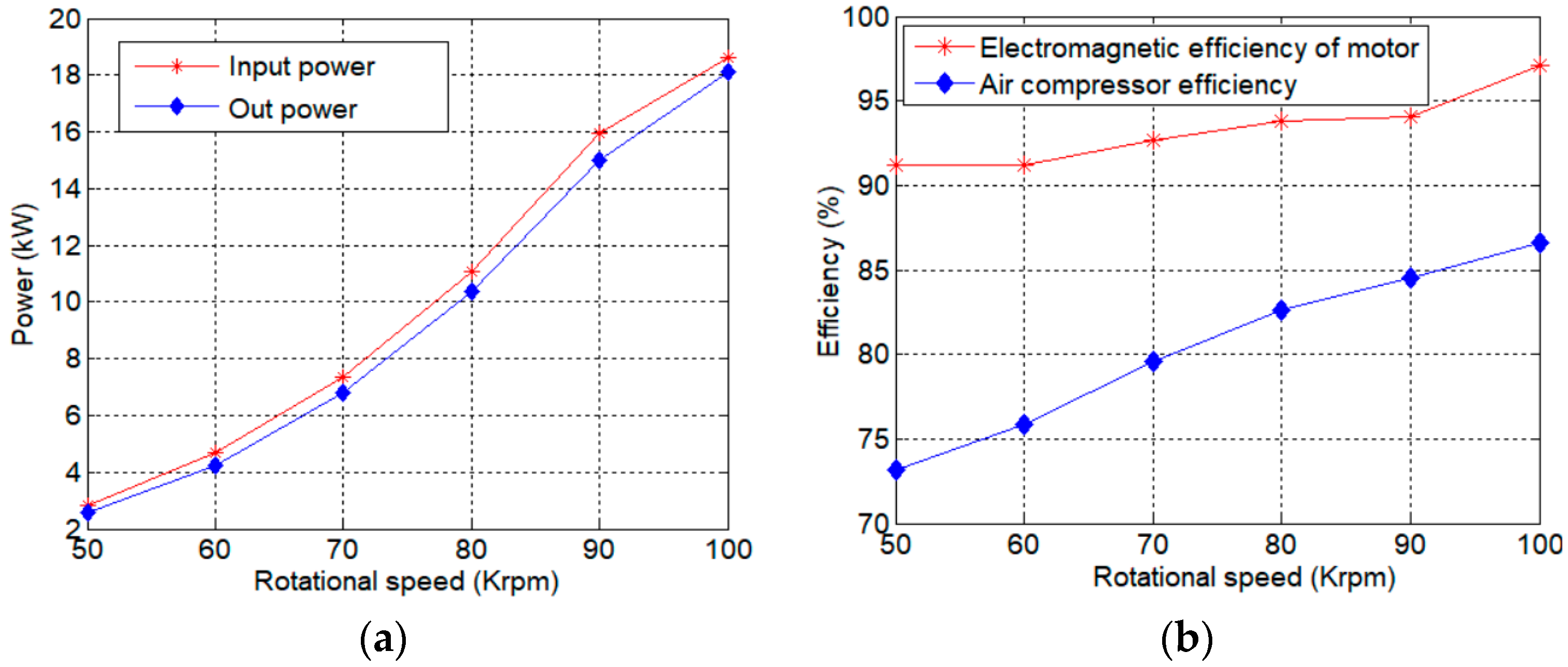
6.2. Test of Motor Efficiency

The motor system performance is significantly influenced by the efficiency, which motor system performance is significantly influenced by the efficiency, which acts as a crucial metric. The power meter is utilized to measure the input power at various motor load speeds, and the electromagnetic power of the motor is calculated using current, torque constant, and speed. In conjunction with the comprehensive motor loss obtained during no-load experimentation, this enables the determination of the output power of the air compressor, subsequently facilitating the calculation of its efficiency. The test result for motor efficiency is shown in Figure 14.
It can seen from Figure 14a that as the speed increases, there is a corresponding increase in both the input power and the electromagnetic power of the motor. This also leads to an improvement in the efficiency of both the air compressor and the electromagnetic power of the motor. When the motor speed reaches 100 krpm, it is capable of achieving an electromagnetic power output of 18 kW, with an electromagnetic efficiency rating of 97.01%. Additionally, the air compressor efficiency is measured at 86.6%. Consequently, the motor successfully meets the designated design requirement.

7. Conclusions

The optimal design of an 18 kW, 100 krpm PMSM has been presented in this paper. The motor model designed here is sufficiently accurate and reliable to be used in an air compressor system for a hydrogen oxygen fuel cell. Taking the minimum rotor loss and maximization of power density as the objective, and the main electromagnetic and mechanical properties of the motor as constraints, the size optimization of the high-speed motor was carried out. Through multi-physical field analysis, the performance of the motor including the electromagnetic field, rotor loss and mechanical strength analysis, and temperature field is estimated more comprehensively and accurately. Through the analysis of the temperature field and water cooling, it was obtained that the water flow of the motor cooling system reaches a minimum of 0.5 L/min during operation. According to the optimized design results, a prototype is made for the tow test and the temperature rise test. The result shows the maximum temperature of motor winding is 109 °C at a speed of 100 krpm. And the absolute error between the design value and the experimental value of the winding temperature is no more than 5 °C and the relative error is no more than 10%. And the efficiency test result of the motor shows that the electromagnetic efficiency achieved 97.01% and the air compressor efficiency was measured at 86.6%. The prototype made according to the optimization design method in this paper can operate stably, and all performances meet the engineering requirements.

Author Contributions

Software simulation, formal analysis, experiment, J.L.; resources, data calculation, experiment, R.D.; programming, experiment, writing—original draft preparation, writing—review and editing, X.R.; supervision, project administration, M.F. All authors have read and agreed to the published version of the manuscript.

Funding

This research was funded by scholarship support from the China Scholarship Council, Grant Number 202006465027.

Data Availability Statement

The data that support the findings of this study are available on request from the corresponding author, upon reasonable request.

Conflicts of Interest

The authors declare no conflicts of interest.

References

  1. Li, Y.; Zhu, C.; Wu, L.; Zheng, Y. Multi-Objective Optimal Design of High-Speed Surface-Mounted Permanent Magnet Synchronous Motor for Magnetically Levitated Flywheel Energy Storage System. IEEE Trans. Magn. 2019, 55, 8202708. [Google Scholar] [CrossRef]
  2. Zhao, J.; Gu, Z.; Li, B.; Liu, X.; Li, X.; Chen, Z. Research on the torque and back EMF performance of a high speed PMSM used for flywheel energy storage. Energies 2015, 8, 2867–2888. [Google Scholar] [CrossRef]
  3. Hong, D.; Hwang, H. Design, Analysis, and Experimental Validation of a Permanent Magnet Synchronous Motor for Articulated Robot Applications. IEEE Trans. Magn. 2018, 54, 8201304. [Google Scholar] [CrossRef]
  4. Kim, J.H.; Kim, D.M.; Jung, Y.-H.; Lim, M.-S. Design of Ultra-High-Speed Motor for FCEV Air Compressor Considering Mechanical Properties of Rotor Materials. IEEE Trans. Energy Convers. 2021, 36, 2850–2860. [Google Scholar] [CrossRef]
  5. Chasiotis, I.D.; Karnavas, Y.L. A Generic Multi-Criteria Design Approach Toward High Power Density and Fault-Tolerant Low-Speed PMSM for Pod Applications. IEEE Trans. Transp. Electr. 2019, 5, 356–370. [Google Scholar] [CrossRef]
  6. Chen, Y.; Ding, Y.; Zhuang, J.; Zhu, X. Multi-Objective Optimization Design and Multi-Physics Analysis a Double-Stator Permanent-Magnet Doubly Salient Machine. Energies 2018, 11, 2130. [Google Scholar] [CrossRef]
  7. Zhang, Y.; McLoone, S.; Cao, W. High speed permanent magnet motor design and power loss analysis. In Proceedings of the 2017 IEEE Transportation Electrification Conference and Expo, Asia-Pacific (ITEC Asia-Pacific), Harbin, China, 7–10 August 2017; pp. 1–6. [Google Scholar]
  8. Park, S.H.; Lee, E.-C.; Park, J.-C.; Hwang, S.-W.; Lim, M.-S. Prediction of Mechanical Loss for High-Power-Density PMSM Considering Eddy Current Loss of PMs and Conductors. IEEE Trans. Magn. 2021, 57, 6300205. [Google Scholar] [CrossRef]
  9. Sun, Y.; Shi, S.; Li, Y.; Wang, Q. Development of quantitative structure-activity relationship models to predict potential nephrotoxic ingredients in traditional Chinese medicines. Food Chem. Toxicol. 2019, 128, 163–170. [Google Scholar] [CrossRef]
  10. Tang, X.; Zhang, Y.; Xu, S. Temperature sensitivity characteristics of PEM fuel cell and output performance improvement based on optimal active temperature control. Int. J. Heat Mass Transf. 2023, 206, 123966. [Google Scholar] [CrossRef]
  11. Milewski, J.; Ryś, P.; Krztoń-Maziopa, A.; Żukowska, G.; Majewska, K.; Zybert, M.; Kowalczyk, J.; Siekierski, M. Structural Investigation of Orthoborate-Based Electrolytic Materials for Fuel Cell Applications. Energies 2024, 17, 2097. [Google Scholar] [CrossRef]
  12. Lu, Z.; Yan, Y. Temperature Control of Fuel Cell Based on PEI-DDPG. Energies 2024, 17, 1728. [Google Scholar] [CrossRef]
  13. Mun, J.; Choi, K.K.; Kim, D.H. System-Level Robust Design Optimization of a Permanent Magnet Motor Under Design Parameter Uncertainties. In Proceedings of the 2022 IEEE 20th Biennial Conference on Electromagnetic Field Computation (CEFC), Denver, CO, USA, 24–26 October 2022; pp. 1–2. [Google Scholar]
  14. Zhang, Y.; Xu, J.; Han, Z.; Wu, Z.; Huang, C.; Li, M. System-Level Optimization Design of Tubular Permanent-Magnet Linear Synchronous Motor for Electromagnetic Emission. In Proceedings of the 2021 13th International Symposium on Linear Drives for Industry Applications (LDIA), Wuhan, China, 1–3 July 2021; pp. 1–4. [Google Scholar] [CrossRef]
  15. Liu, Y.X.; Li, L.Y. The Optimization Design of Short-Term High-Overload Permanent Magnet Motors Considering the Nonlinear Saturation. Energies 2018, 11, 3272. [Google Scholar] [CrossRef]
  16. Wu, J.; Zhu, X.; Xiang, Z.; Fan, D.; Quan, L.; Xu, L. Robust Optimization of a Rare-Earth-Reduced High-Torque-Density PM Motor for Electric Vehicles Based on Parameter Sensitivity Region. IEEE Trans. Veh. Technol. 2022, 71, 10269–10279. [Google Scholar] [CrossRef]
  17. Lei, G.; Wang, T.; Zhu, J.; Guo, Y.; Wang, S. System-Level Design Optimization Method for Electrical Drive Systems—Robust Approach. IEEE Trans. Ind. Electron. 2015, 62, 4702–4713. [Google Scholar] [CrossRef]
  18. Neto, M.G.; da Silva, F.F.; Branco, P.J.d.C. Operational Analysis of an Axial and Solid Double-Pole Configuration in a Permanent Magnet Flux-Switching Generator. Energies 2024, 17, 1698. [Google Scholar] [CrossRef]
  19. Shuhua, F.; Huan, L. High Power Density PMSM with Lightweight Structure and High-Performance Soft Magnetic Alloy Core. IEEE Trans. Appl. Supercond. 2019, 29, 0602805. [Google Scholar]
  20. Huang, Z.; Fang, J.; Liu, X.; Han, B. Loss Calculation and Thermal Analysis of Rotors Supported by Active Magnetic Bearings for High-Speed Permanent-Magnet Electrical Machines. IEEE Trans. Ind. Electron. 2016, 63, 2027–2035. [Google Scholar] [CrossRef]
  21. Wang, W.; Tang, Q.; Xu, X.; Gong, S. Finite element analysis of normal contact stiffness between real rough surfaces based on ANSYS. In Proceedings of the 2012 Fourth International Conference on Computational and Information Sciences (ICCIS), Chongqing, China, 17–19 August 2012; pp. 127–130. [Google Scholar]
  22. Ng, K.; Zhu, Z.Q.; Howe, D. Open-circuit field distribution in a brushless motor with diametrically magnetised PM rotor, accounting for slotting and eddy current effects. IEEE Trans. Magn. 1996, 32, 5070–5072. [Google Scholar] [CrossRef]
  23. Aubry, J.; Ahmed, H.B.; Multon, B. Sizing Optimization Methodology of a Surface Permanent Magnet Machine-Converter System Over a Torque-Speed Operating Profile: Application to a Wave Energy Converter. IEEE Trans. Ind. Electron. 2012, 59, 2116–2125. [Google Scholar] [CrossRef]
  24. Jędryczka, C.; Knypiński, Ł.; Demenko, A.; Sykulski, J.K. Methodology for Cage Shape Optimization of a Permanent Magnet Synchronous Motor Under Line Start Conditions. IEEE Trans. Magn. 2018, 54, 3. [Google Scholar] [CrossRef]
  25. Mohammad, H.M.; Rodrigo, C.P. Finding Optimal Performance Indices of Synchronous AC Motors. IEEE Trans. Magn. 2017, 53, 8104004. [Google Scholar] [CrossRef]
  26. Han, B.; Xu, Q.; Yuan, Q. Multiobjective Optimization of a Combined Radial-Axial Magnetic Bearing for Magnetically Suspended Compressor. IEEE Trans. Ind. Electron. 2015, 63, 2284–2293. [Google Scholar] [CrossRef]
  27. Tong, W.; Sun, R.; Zhang, C.; Wu, S.; Tang, R. Loss and Thermal Analysis of a High-Speed Surface-Mounted PMSM With Amorphous Metal Stator Core and Titanium Alloy Rotor Sleeve. IEEE Trans. Magn. 2019, 55, 8102104. [Google Scholar] [CrossRef]
  28. Zhang, C.; Chen, L.; Wang, X.; Tang, R. Loss Calculation and Thermal Analysis for High-Speed Permanent Magnet Synchronous Machines. IEEE Access 2020, 8, 92627–92636. [Google Scholar] [CrossRef]
  29. Dong, B.; Wang, K.; Han, B.; Zheng, S. Thermal Analysis and Experimental Validation of a 30 kW 60,000 r/min High-Speed Permanent Magnet Motor with Magnetic Bearings. IEEE Access 2019, 7, 92184–92192. [Google Scholar] [CrossRef]
Figure 1. Configuration of motor in air compressor.
Energies 17 02722 g001
Figure 2. Axial cross section of motor.
Energies 17 02722 g002
Figure 3. Schematic diagram of the optimization process.
Energies 17 02722 g003
Figure 4. Simulation wave of eddy current loss.
Energies 17 02722 g004
Figure 5. Simulation wave of iron loss.
Energies 17 02722 g005
Figure 6. Simulation wave of phase current.
Energies 17 02722 g006
Figure 7. Stress simulation results. (a) Mesh plot; (b) Stress simulation of permanent magnet; (c) Stress simulation of sleeve.
Energies 17 02722 g007
Figure 8. Magnetic field distribution of motor. (a) Magnetic field of stator and rotor; (b) Magnetic field of PM; (c) Magnetic flux distribution.
Energies 17 02722 g008
Figure 9. Temperature field distribution.
Energies 17 02722 g009
Figure 10. Temperature field distribution of windings: (a) at a rotation speed of 20 krpm; (b) at a rotation speed of 100 krpm.
Energies 17 02722 g010
Figure 11. Winding temperature distribution cloud diagram with varying cooling water flow.
Energies 17 02722 g011
Figure 12. Photo of the motor test bench.
Energies 17 02722 g012
Figure 13. Test curve of winding temperature changing with speed.
Energies 17 02722 g013
Figure 14. Test curve of winding temperature changing with speed. (a) Power; (b) Efficiency.
Energies 17 02722 g014
Table 1. Design variables of motor optimization.
NameParametersValue Range
d0Outer diameter of PM, mm28 ≤ d0 ≤ 32
d1Inner diameter of PM, mm20 ≤ d1 ≤ 30
d2Outer diameter of stator, mm80 ≤ d2 ≤ 94
lsleThickness of rotor sleeve, mm2 ≤ lsle ≤ 5
lgapLength of air gap, mm1 ≤ lgap ≤ 4
laxAxial length of motor, mm6 ≤ lax ≤ 10
Table 2. Key parameters of motor optimization.
NameValueNameValue
Rotor topologySurface-
mounted PM
Connection configuration of WindingsDouble layer/star connection
Outer diameter of stator94 mmCore length8 mm
Inner diameter of stator45 mmPitch5
Outer diameter of magnetic steel32 mmNumber of parallel branches2
Length of air gap4 mmNumber of conductors per slot10
Axial length of motor8 mmInner diameter of magnetic steel20 mm
Outer diameter of sheath37 mmslot filling rate 0.8
Sleeve materialTC11Number of stator slots12
Number of parallel branches2Number of pole pairs1
Nominal diameter of wire0.63 mmMagnet materialNdFeB
Table 3. Heat source distribution inside motor.
Heat SourceLoss (W) Volume (m3)Heat Generation Rate (W/m3)
Windings255 2.31 × 10 4 1.1 × 10 6
Stator core152 1.87 × 10 4 8 × 10 5
Magnetic steel143 1.72 × 10 5 3.03 × 10 6
Table 4. Material parameters of motor components.
ComponentDensity
ρ (kg/m3)
Heat Capacity C
( J / K · kg )
Thermal Conductivity λ (W/mK)
Equivalent insulation in slots780 1301 0.125
Windings (copper)8933 3850 401
Waterproof jacket (PEEK)1300 2200 0.43
Sleeve (TC11)44806006.3
Stator (10JNEX900) 7650 440 35
Magnetic steel7400 502 8.93
Support elements (4Cr13)7750 460 29.3
Water997 4181.7 0.6069
Air1.185 1004.4 0.0263
Disclaimer/Publisher’s Note: The statements, opinions and data contained in all publications are solely those of the individual author(s) and contributor(s) and not of MDPI and/or the editor(s). MDPI and/or the editor(s) disclaim responsibility for any injury to people or property resulting from any ideas, methods, instructions or products referred to in the content.

