Article

Optimization of Dropwise Condensation of Steam over Hybrid Hydrophobic–Hydrophilic Surfaces via Enhanced Statistically Based Heat Transfer Modelization

Dipartimento Politecnico di Ingegneria e Architettura (DPIA), Università degli Studi di Udine, Via delle Scienze 206, 33100 Udine, Italy
*
Author to whom correspondence should be addressed.
These authors contributed equally to this work.
Energies 2024, 17(11), 2742; https://doi.org/10.3390/en17112742
Submission received: 3 May 2024 / Revised: 31 May 2024 / Accepted: 3 June 2024 / Published: 4 June 2024
(This article belongs to the Collection Advances in Heat Transfer Enhancement)

Abstract

:
Steam condensation over a hybrid hydrophobic–hydrophilic surface is modeled via simplified heat transfer modelization. Filmwise condensation is assumed over the hydrophilic region. The standard film model is improved, accounting for the liquid flow rate crossing the hydrophobic–hydrophilic boundaries. A threshold for flooding occurrence is also presented. Dropwise condensation is assumed over the hydrophobic region. Compared to the heat transfer models in the literature, based on the statistical drop size distribution, a novel correlation is used for the size distribution of small droplets. The correlations of both the liquid flow rate crossing the hydrophobic–hydrophilic boundary and the size distribution of small drops are derived via Lagrangian simulations, using an in-house code previously developed and validated by the authors. The heat transfer model is validated with experimental data in the literature involving a hybrid surface, composed by alternate vertical hydrophobic–hydrophilic stripes. Then, the optimization of the hybrid surface geometry is performed in terms of hydrophobic width and hydrophilic width, with the aim of enhancing the heat flux.

1. Introduction

Steam condensation over a solid substrate is of great interest for many practical applications, such as heat exchanger design. Dropwise condensation (DWC) over an inclined, hydrophobic surface, characterized by a static contact angle θ > 90 , is known to augment the heat transfer coefficient by about one order of magnitude, if compared to the filmwise condensation (FWC) regime. Indeed, solid surface regeneration due to the motion of large droplets driven by gravity, which is observed in case of DWC on an inclined plate, promotes the nucleation of new droplets and reduces the thermal resistance of the wetting layer. The reduction of the departure radius is usually achieved by means of hydrophobic ( θ > 90 ) and superhydrophobic ( θ > 150 ) surfaces, characterized by low contact angle hysteresis. Different surface coatings can be used to ensure surface hydrophobicity [1,2,3]. For example, in SAMs coating, such as the one in [4,5], self-assembled monolayers (SAMs) form by the adsorption of long-chain organic molecules onto an appropriate solid substrate. Other methods to reduce the droplet departure radius include the coalescence-induced jump of droplets, promoted by nanostructured superhydrophobic surfaces [6], and the implementation of surfaces characterized by wettability gradients [7]. In the theoretical analysis of [8], the details of the nanostructured surfaces, modeled as a series of equally spaced nano-pillars, are discussed, and the transition between the possible wetting stages, which include Cassie and Wenzel states, is explained. In the recent years, a lot of effort has been put into the implementation of the so-called hybrid surfaces, usually characterized by a pattern of recursive hydrophobic and hydrophilic regions of a certain geometry. The main goal of such surfaces is that the maximum radius on the hydrophobic domain, where the DWC regime is usually observed, can be controlled via a proper design of the surface geometry, while the hydrophilic regions, wetted by a continuous liquid film, ensures the renewal of the hydrophobic surface and allows for a fast liquid drainage. On the other hand, the heat transfer performances through the continuous wetting layer are the result of FWC. Thus, a proper design of the surface geometry is crucial in order to increase the heat transfer performance of the standard hydrophobic surface. Alwazzan et al. [2,9] experimentally investigated condensation of vapor with a small concentration of non-condensable gases (lower than 7%) over a horizontal copper tube, characterized by alternate mini-scale straight patterns of hydrophobic and less hydrophobic regions. Different geometries were tested and improvements in the heat transfer performances were observed, compared to the standard hydrophobic surfaces. Peng et al. [5] experimentally investigated steam condensation of water vapor down a vertical test section, characterized by alternate hydrophobic–hydrophilic stripes of fixed width. Different geometries were tested and an optimal configuration was found. A more complex geometry, characterized by an inverted V-shaped channels design with alternate hydrophobic–hydrophilic inclined stripes and a vertical hydrophilic region that collects the condensate and ensures an efficient liquid drainage, was experimentally investigated in [10], in the case of moist air condensation.
The evolution of a condensing droplet population is often investigated via the so-called individual-based models (IBM) [6,11,12,13,14,15], that follow the evolution of every droplet of a population (including nucleation, growth due to condensation and coalescence, motion) via a Lagrangian approach. The large computational costs related to the individual-based models makes this approach unsuitable to investigate a large number of configurations and the literature analysis are often limited to a small portion of condensing surface, due to the high nucleation density characterizing steam condensation on hydrophobic surfaces. However, high-fidelity IBM allows us to access information on the small drop population [11], characterized by droplets of radii down to the nanometers and, thus, not accessible via a standard experimental approach. Indeed, statistical information such as the size distribution of small droplets are crucial for the implementation of an accurate probability-based model (PBM), which has the advantage of cutting computational costs. In the pioneering experimental analysis of Le Fevre and Rose [16] an empirical correlation to predict the size distribution of the large drop population, the growth of which is driven by coalescence process, was developed. Such a correlation, extensively validated with experimental evidences [5], now represents an important benchmark for the validation of IBM models [6,11,12,13] and is still included in most of the PBMs [17,18,19,20]. A theoretical correlation for the size distribution of small droplets was derived in [17] via the solution of the population balance. Based on the developed correlation for the drop size distribution and modeling the heat transfer through a single droplet via a series of thermal resistance, a novel PBM was developed to predict the heat flux under DWC. A similar correlation for the size distribution of small droplets was derived in [18]. However, numerical results from IBM simulations [11,21,22] show discrepancies between the computed small size distribution and the theoretical correlation of [17]. Since the Rose correlation [23] is known to overestimate the nucleation density, required by PBMs to define the threshold between small and large droplets, an updated model to include the effect of the coating thickness in the calculation of both the nucleation radius and the nucleation density was presented in [19,20] and integrated with the PBM of [17]. The optimization of a hybrid hydrophobic–hydrophilic surface geometry via a PBM of the condensation process was firstly conducted in [24], assuming DWC regime over the hydrophobic region and FWC over the hydrophilic region. However, the effect of the coating thermal resistance on the nucleation radius, introduced by [19,20] and required for an accurate prediction of the effective nucleation density as a function of the substrate subcooling, was not considered. Furthermore, the film was modeled in [24] as a liquid layer of uniform thickness: such a modelization does not provide any information about the eventual occurrence of flooding, which is crucial to predict the eventual degradation of heat transfer performances, observed when the liquid film overrun the hydrophilic boundary.
The aim of this work is the numerical investigation of steam condensation over a hybrid surface via a simplified modelization. In particular, the global heat flux of the hybrid surface is decomposed into two contributions: one arising from the dropwise condensation, which is assumed over the hydrophobic domain; one arising from the filmwise condensation over the hydrophilic region, covered by a continuous wetting layer. The dropwise condensation heat flux is estimated via a probability-base modelization, which relies the knowledge of the drop size distribution. Compared to the model of [19,20], a new correlation for the size distribution of the small drops is implemented, following [21,22]. The standard film theory, proposed by Nusselt [25], is here enhanced in order to account for the presence of the rivulets flowing through the narrow wettable stripes and for the liquid flow rate exchanged between hydrophobic and hydrophilic regions through the shared boundaries. Furthermore, the eventual flooding condition, occurring when the liquid overruns the hydrophilic boundaries, is modeled. The experimental test case of [5], which involves the steam condensation of water vapor over a circular disc with vertical, alternate hydrophobic–hydrophilic stripes of fixed width, is replicated. The numerical model is validated with the experimental data of [5]. Then, the optimization of the hybrid surface geometry is conducted, in order to the maximize the global heat flux at a given substrate subcooling.

2. Physical Model

2.1. Problem Statement

The steam condensation of water vapor over a hybrid surface was analyzed. The hybrid surface geometry experimentally investigated by [5], defined as a disc with alternate hydrophobic and hydrophilic vertical stripes of width L D and L F as sketched in Figure 1, was considered. As proven by the experimental evidence of [5], the dropwise condensation regime takes place over the hydrophobic stripes, while the hydrophilic stripes are covered by a continuous liquid film. It was also observed in [5] that, when the base surface of a droplet growing on the hydrophobic domain partially stands on the hydrophilic region, the surface tension forces induce the droplet migration to the more wettable region, as pointed out in the right side of Figure 1. Thus, the hydrophilic stripe ensures a fast condensate removal, which in turn allows the hydrophobic surface renewal. The maximum radius of the droplets growing on the hydrophobic region, which is also an important parameter of DWC, can be controlled through a proper design of the hybrid surface geometry
r m a x = L D 2 sin θ
with θ > 90 being the static contact angle over the hydrophobic domain and L D being the width the hydrophobic stripes. The specific heat flux contributions q D and q F , arising from dropwise condensation and filmwise condensation respectively, are computed via the dedicated models: a probability-based model is developed to estimate the DWC heat flux through the hydrophobic stripes; a theoretical film model is developed to estimate the FWC heat flux through the hydrophilic stripes. The two models are integrated to estimate the global heat flux of the hybrid surface as
q = q D L D + q F L F L D + L F

2.2. Dropwise Condensation Model

Following the single-drop heat transfer model of [17,19,20], the droplet is discretized via a series of four thermal resistances: the conductive resistance through the coating layer; the conductive resistance through the liquid droplet; the vapor–liquid interface thermal resistance; the free surface curvature thermal resistance. In order to evaluate the conductive resistance through the liquid, the droplet is modeled as a spherical cap with a prescribed contact angle and uniform temperatures are assumed for the base surface and the liquid–vapor interface surface. Thus, the heat flux through a condensing droplet of radius r is given in [17,19,20] as
q d r o p = Δ T π r 2 1 r 0 r δ c λ c sin 2 θ + θ r 4 λ l sin θ + 1 2 α i 1 cos θ
where δ c is the coating thickness, λ c is the coating thermal conductivity, r 0 is the critical nucleation radius and α i is the interfacial heat transfer coefficient
r 0 = 2 T s σ l v ρ l h l v T s T w , α i = 2 σ 2 σ 1 2 π R g T s ρ v h l v 2 T s
with 0 < σ 1 being the accommodation coefficient ( σ = 1 for steam condensation of pure vapor). The specific heat flux of the hydrophobic surface, covered by a population of condensing droplets, can be computed as in [20]
q D = r n r e q d r o p n r d r + r e r m a x q d r o p N r d r
where r n is the nucleation radius, r e is the characteristic coalescence radius, r m a x is the maximum droplet radius, n r is the size distribution of the small drop population and N r is the size distribution of the large drop population. The conduction process drives the droplet growth for r < r e , while the coalescence process drives the droplet growth for r > r e . The empirical correlation of Le Fevre Rose [16]
N r = 1 3 π r 2 r m a x r m a x r 2 / 3
is used to estimate the size distribution of large droplets, characterized by r > r e . It was numerically [11] and experimentally [5] verified that Equation (6), originally derived for a standard hydrophobic surface characterized by gravity-driven motion of the droplets, is still valid in the case of hybrid surfaces (i.e., droplet motion induced by surface tension forces), such as the one considered in the present work. Only theoretical correlations are available for the size distribution of the small droplets. It was shown in [11,21] that the one proposed by [17], derived via the population balance theory, is not accurate, due to the assumption that the sweeping time, correlated to the frequency of the coalescence events, is a constant. Indeed, it was numerically proved that the sweeping time changes with the droplet radius [21,22]. Thus, an updated correlation, which estimates the sweeping time as a function of the drop radius, was derived for the small size distribution. Following [17], the population balance theory gives
d G n r d r + n r τ = 0
with G being the droplet growth rate and τ being the sweeping time. Equation (7) can be solved via separation of variables [17], yielding
n r = n e G e G r r e d r G τ
where n e = n r ( r e ) is the small size distribution of a droplet with radius r e , which must match the large size distribution, n r ( r e ) = N r ( r e ) , and G e is the growth rate of a droplet with radius r e . Assuming that condensation drives heat transfer, q d r o p = m ˙ c h l v , the droplet growth rate G can be evaluated as
G = d r d t = Δ T 1 r 0 / r ρ l h l v 1 cos θ 2 2 + cos θ × δ c λ c sin 2 θ + θ r 4 λ l sin θ + 1 2 α i 1 cos θ 1
It was shown in [21,22] that the sweeping time τ , assumed constant in [17], linearly depends on the droplet radius
τ = τ e r r e
Substituting Equations (9) and (14) in the population balance, Equation (8), yields
n r = n e r r e r e r 0 r r 0 r + B r e + B exp C 1 + C 2 A
C 1 = r e τ e r e r , C 2 = r e τ e r 0 + B log r e r 0 r r 0
with coefficients A , B being equal to
A = λ l Δ T ρ l h l v 4 sin θ θ 1 cos θ 2 2 + cos θ , B = 4 λ l δ c λ c θ sin θ + 2 λ l sin θ θ 1 cos θ
Following [17], the sweeping time τ e must be determined to match the distribution for large droplets:
d ( log n r ) d ( log r ) = 8 3 , τ e = 1 A 3 r e 2 r e + B 2 11 r e 2 14 r e r 0 + 8 B r e 11 B r 0
It was proved in [22] that the dropwise condensation heat flux, computed via a high-fidelity IBM code, is accurately predicted via Equation (5), which is the base of a standard PBM, if the size distribution of small drops is derived assuming that the sweeping time linearly depends on the droplet radius (as is conducted in the present study), while using the correlation of [17] underestimates the heat flux of about 18%.
The updated correlation for the size distribution of the small drop population, provided by Equations (11) and (12), is compared in Figure 2 with the theoretical correlation provided in [17], which assumes a constant sweeping time. Note that a higher drop size distribution is always predicted by the updated correlation, due to the higher sweeping frequency. The characteristic coalescence radius r e is evaluated at different values of coating thermal resistance according to the model proposed by [19,20]. Thus, r e is estimated from the nucleation density ρ n , which is in turn estimated via the well-known Rose correlation [23] as a function of the nucleation radius:
r e = 1 2 ρ n , ρ n = 0.037 r n 2
As reported in the literature [20], the Rose correlation overestimates the effective nucleation density, which usually ranges 10 9 ÷ 10 15 m 2 for the steam condensation on a solid surface, if the critical nucleation radius r 0 is considered. However, it was proved that the effective nucleation radius r n depends on the solid surface characteristics and a dedicated model was proposed by [19,20] to calculate r n via the maximization of the change in availability,
Δ Ψ = ρ l h l v T s π r sin θ 3 0 θ Δ T + q d r o p δ c π r 2 sin 2 θ λ c + q d r o p ϕ 4 π r sin θ λ l 1 cos ϕ 2 sin 4 ϕ d ϕ + σ l v 2 3 cos θ + cos 3 θ π r 2
with Δ T = T s T w and q d r o p being calculated via Equation (3).
The influence of the coating specific thermal resistance, defined as δ c / λ c , is investigated in Figure 3 and Figure 4, which refer to the steam condensation of water at saturation temperature equal to T s = 100 ° C over a hydrophobic substrate, characterized by static contact angle of θ = 120 . Figure 3 shows the nucleation radius, estimated via the maximization of the change in availability Δ Ψ , as a function of the substrate subcooling, at different values of the specific coating thermal resistance. It can be observed that the presence of a hydrophobic coating leads to an increase in the nucleation radius. Knowing the effective nucleation radius is crucial, since it affects the predicted nucleation density and, thus, the coalescence radius, see Equation (15), in turn required for an accurate estimate of the dropwise condensation heat flux. The heat flux through a single condensing droplet, calculated via Equation (3), is shown as a function of the droplet radius in Figure 4a, with the dashed line representing the heat flux of a newly nucleated droplet, characterized by r = r n . Figure 4b provides the size distribution of both the small and the large droplet population: the maximum radius, required by the correlation for the large size distribution, is set to half the capillary length l c = σ l v / ( ρ l g ) , while the characteristic coalescence radius, which defines the threshold between small and large drops, is estimated from the nucleation radius according to Equation (15).
The effects of the subcooling and of the droplet departure radius on DWC heat flux, whose calculation relies on the heat transfer model through a single droplet and on the drop size distribution, were investigated. In particular, Figure 5a shows the global heat flux as a function of the substrate subcooling, at different values of the coating specific resistance. As expected, higher values of the substrate subcooling give higher specific heat fluxes, with an almost linear correlation between Δ T and q D for a sufficiently high subcooling. The coating, which acts as an additional thermal resistance opposing to the heat transfer process [20], decreases the heat flux. The effect of the static contact angle, which depends on the coating characteristics, is not considered. On the other hand, we may be interested in the effect of the departure radius. For a hydrophobic surface, the departure radius is equal to the droplet moving radius, which is strongly influenced by the contact angle hysteresis. However, in presence of hybrid hydrophobic–hydrophilic surfaces, the maximum radius may be imposed through a proper design of the surface geometry [5,24]. Figure 5b proves that the specific heat flux increases with decreasing departure radius r m a x . Indeed, small droplets, r n r r e , are characterized by a higher specific heat flux compared to large drops, see Figure 4a, and, thus, the renewal of the hydrophobic surface ensures higher heat transfer performances.

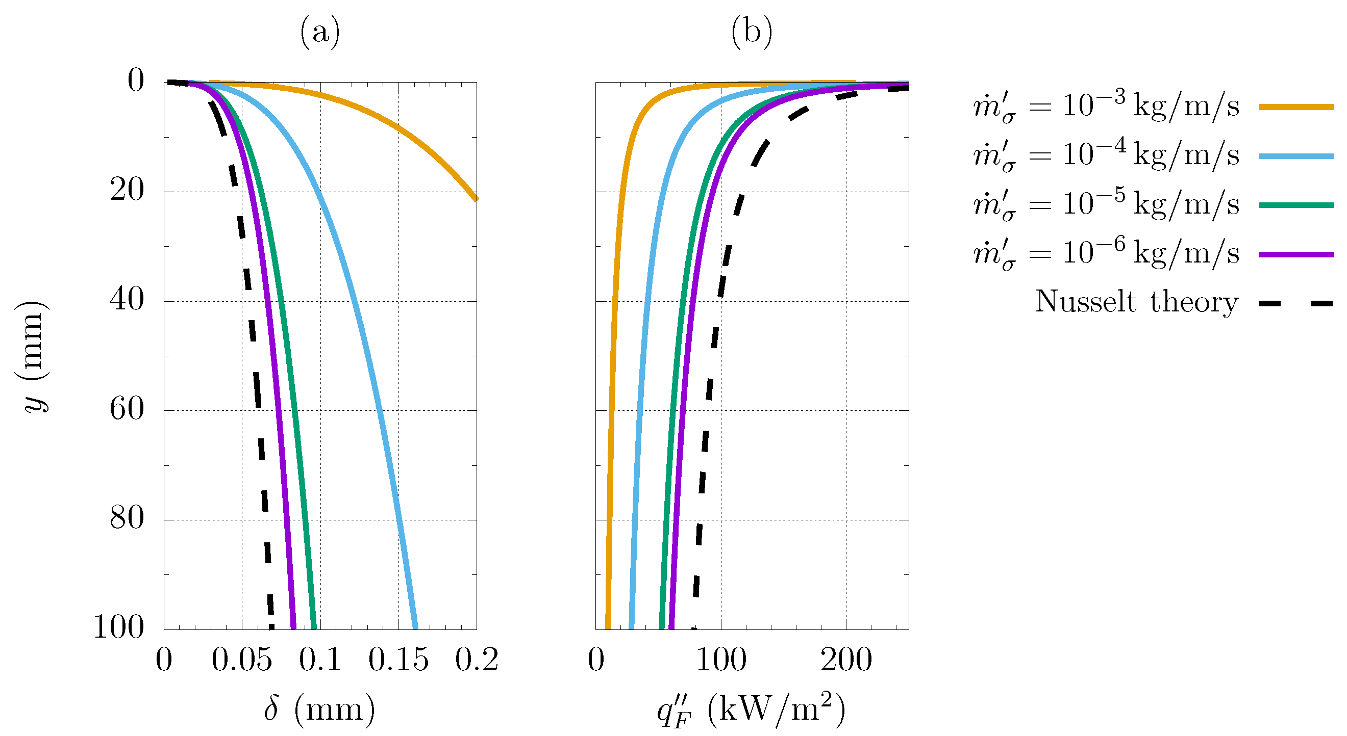
2.3. Filmwise Condensation Model

Assuming that the liquid flowing down a vertical hydrophilic stripe forms a rivulet with the circular section and assuming a parabolic velocity profile across the film thickness, the mass flow rate is equal to
m ˙ = F θ r ρ l ρ l ρ v g δ 3 L F 3 μ l
where δ is the maximum height of the rivulet, L F is the hydrophilic stripes width and F θ r comes from the integration of the parabolic velocity profile across the rivulet section,
F θ r = θ r 3 8 + 3 2 cos 2 θ r + 1 32 sin ( 4 θ r ) sin ( 2 θ r ) 1 1 4 sin 2 θ r sin θ r 1 cos θ r 3
with θ r being the rivulet contact angle, which in turn depends on the rivulet height δ and on the rivulet width L F :
θ r = arccos 1 2 δ L F 2 1 + 2 δ L F 2
The liquid flow rate at a distance y from the top of the plate is also equal to
m ˙ = m ˙ c + m ˙ σ y
where y denotes the distance from the top of the hydrophilic stripes, m ˙ c is the condensate flow rate formed at the free surface of the liquid film and m ˙ σ is the flow rate per unit length, which migrates from the hydrophobic region to the hydrophilic region due to capillary forces. Following Nusselt theory [25], the condensate flow rate can be expressed by applying the energy balance to a portion of the rivulet:
d m ˙ c d y = λ l L F T s T w δ h l v sin θ r θ r
Combining Equations (17), (20), and (21) gives the differential equation
F θ r ρ l ρ l ρ v g δ 2 μ l d δ d y = λ l T s T w δ h l v sin θ r θ r + m σ L F
the solution of which gives the film thickness δ ( y ) as a function of the vertical, downhill coordinate. If the rivulet contact angle, which depends on the rivulet thickness δ is assumed constant over y, Equation (22) can be analytically solved, yielding
u 3 3 3 2 C u 2 + 3 C 2 u C 3 log u C = 11 6 C 3 + y D
u = δ + C , C = λ l L F T s T w h l v m ˙ σ sin θ r θ r , D = F θ r ρ l ρ l ρ v g L F μ l m ˙ σ
which has one positive root δ . Since the rivulet contact angle θ r depends on the rivulet height δ , the solution of Equation (23) must be iterated until the convergence of δ is obtained. It is important to point out that the updated filmwise condensation model, derived assuming a parabolic velocity profile inside a rivulet with circular cross section, is strictly valid at leading surface tension forces (i.e., for narrow hydrophilic stripes), while the liquid inertia may affect the film hydrodynamics for large hydrophilic width, usually correlated to higher flow velocities.
The film thickness and the heat flux through the liquid layer along a vertical plate are shown in Figure 6 at different values of the migrating flow rate per unit length, coming from the hydrophobic region. Results are referred to as the steam condensation of water at a saturation temperature of T s = 100 ° C over hydrophilic stripes of width L F = 0.45 mm and substrate temperature T w = 94 . Note that increasing m ˙ σ worsens the heat transfer, since the film thickness increases and, thus, the temperature gradient through the liquid layer decreases, giving a lower heat flux. If the contribution of the migrating flow rate is neglected, m ˙ σ = 0 , the proposed model also predicts a lower heat flux compared to the standard Nusselt film theory, see Figure 6b.
Flooding occurs when the liquid flowing down the vertical stripe overruns the hydrophilic boundaries. Thus, the flooding threshold is defined by the liquid flow rate corresponding to a rivulet with a contact angle equal to 90 . Further increasing the liquid flow rate, the contact angle will increase and a portion of the liquid will stand on the hydrophobic domain. The critical flow rate corresponding to θ r = 90 is derived via the integration of the parabolic velocity profile across the rivulet section
m ˙ c r = π 128 ρ l ρ l ρ v g L F 4 μ l
Since the condensate flow rate, produced over the hydrophobic region, must be removed through the hydrophilic stripes, the migrating flow rate per unit length m ˙ σ can be estimated from the specific heat flux q D , calculated for the contribution of dropwise condensation
m ˙ σ = q D L D h l v
where L D is the hydrophobic stripes width. Once m ˙ σ is known, the rivulet height δ of a stripe of height y = H is calculated via Equations (23) and (24) and the liquid flow rate m ˙ is evaluated via Equation (17). The specific heat flux due to filmwise condensation process over a single stripes of surface H L F is finally estimated as
q F = m ˙ m ˙ σ H h l v H L F

3. Results

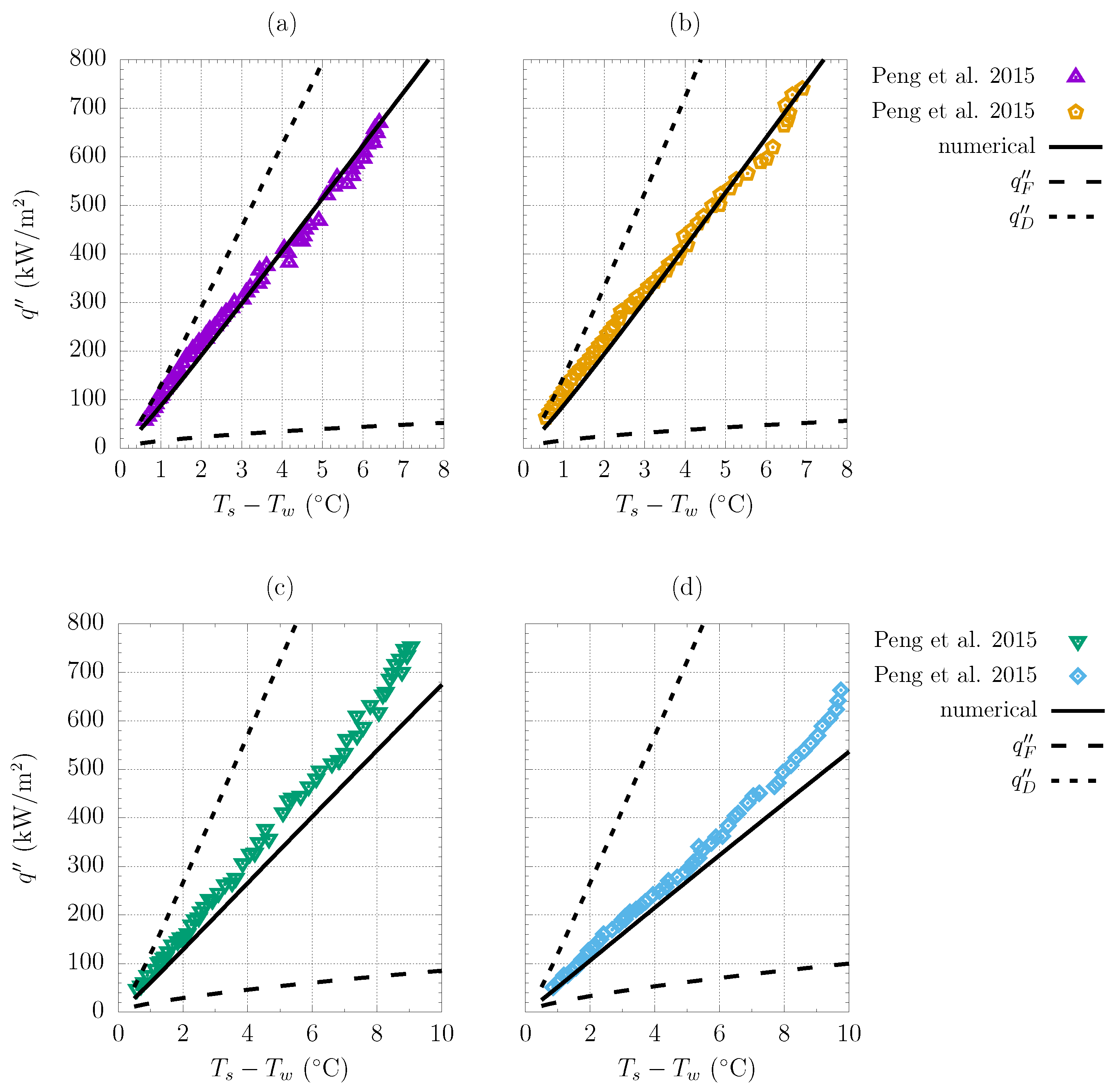
3.1. Model Validation

The experimental setup of [5] was replicated using the simplified model described in Section 2. Thus, the steam condensation of water at a saturation temperature of 100 ° C over the hybrid surface of Figure 1, defined by a vertical disc with alternate hydrophobic–hydrophilic stripes, was investigated. The static contact angle over the hydrophobic domain was set to θ = 120 , according to [5]. Hydrophobicity was achieved in [5] via an SAM coating, whose preparation was obtained as follows: polishing of the copper surface; immersion of the copper sample into an n-octadecyl mercaptan solution at 70 ° C . Locally masking the polished copper surface and sandblasting before the immersion of the sample (monolayers cannot be coated on the sandblasted copper substrate) allows a hybrid hydrophobic–hydrophilic surface to be obtained. The order of magnitude of the specific thermal conductivity of the SAMs coating is about 10 7 m 2 K / W [26], however the value of δ c / λ c is not provided in [5]. Thus, we first characterized the hydrophobic surface with the heat flux data referred to as the fully hydrophobic configuration. To do so, we imposed L F = 0 and we derived the departure radius to be used in the DWC model via the balance between gravitational forces and surface tension forces acting on a still droplet,
r m a x = 12 π 2 σ l v cos θ r e c cos θ a d v ρ l g 1 cos θ 2 2 + cos θ
with θ r e c = 102 and θ a d v = 142 being the receding contact angle and the advancing contact angle, whose values are also provided in [5]. In order to characterize the surface, the coating thermal resistance was determined via minimization of the root mean square error with the experimental data, available for surface subcoolings up to Δ T = 8 ° C in case of fully hydrophobic surface. The value δ c / λ c = 3.39 × 10 7 m 2 K / W was obtained, which is consistent with data reported in the literature [26].
The corresponding heat flux as a function of the substrate subcooling is compared with the experimental points in Figure 7a, showing a great agreement over the whole range of Δ T . Furthermore, the nucleation density, derived via Equation (15) as a function of the computed nucleation radius r n , which in turn depends on the substrate subcooling, also falls in the typical range of 10 9 ÷ 10 15 , as proved by Figure 7b.
Then, we validated the numerical model, including both the DWC model and the FWC model, with the experimental heat flux data of [5] relating the hybrid surface configuration. Compared to the data used for the surface characterization in case of a fully hydrophobic surface, we have different values of the departure radius, which depends on the hybrid geometry, and we have the additional effect of the liquid film flowing down the hydrophilic stripes. Since the test section is a cylindrical disc with alternate hydrophobic and hydrophilic stripes, the calculation of the filmwise condensation heat flux must take into account that we have stripes of different height,
q F = k = 1 n q F y k y k k = 1 n y k , n = 2 R L F + L D , y k = 2 R 1 L F + L D R k L D + L F / 2 R 2
with q K y k being the heat flux of a hydrophilic stripe of height H = y k , evaluated via Equation (27), and n being the number of hydrophilic stripes. Figure 8a,b, referring to approximately the same hydrophilic width L F = 0.45 mm and to different hydrophobic widths L D = 0.78 , 0.55 mm , show almost a perfect agreement between numerical results and experimental data. Indeed, maximum errors of 6.9% and 10.7% between the predicted heat fluxes and the experimental data of [5] were observed in Figure 8a and Figure 8b, respectively: for the most of the experimental data points, the discrepancy with the predicted heat flux is lower than the experimental uncertainty of 9.2% reported in [5]. A good agreement was also observed for higher values of the hydrophilic width ( L F = 1.33 , 2.1 mm ) at low substrate subcoolings, while a discrepancy up to 19.3% was observed for higher subcoolings when L F = 2.1 mm , see Figure 8c,d. Such a discrepancy is due to the assumptions made to develop the film model (i.e., the liquid flows with a parabolic velocity profile through a rivulet with circular section of width L F ), which are strictly valid at leading surface tension forces (i.e., narrow hydrophilic stripes). Furthermore, the fluctuations induced by the migrating droplets, which are more evident for increasing r m a x , in turn defined by the hydrophobic width, may also affect the hydrodynamics through the wetting layer, as reported in [2,9]. Thus, we could expect the model to be accurate in the limit of small L D , L F (that is, the range of application of hybrid surfaces), while the assumptions are weaker in the case of large hydrophobic–hydrophilic stripes’ width.

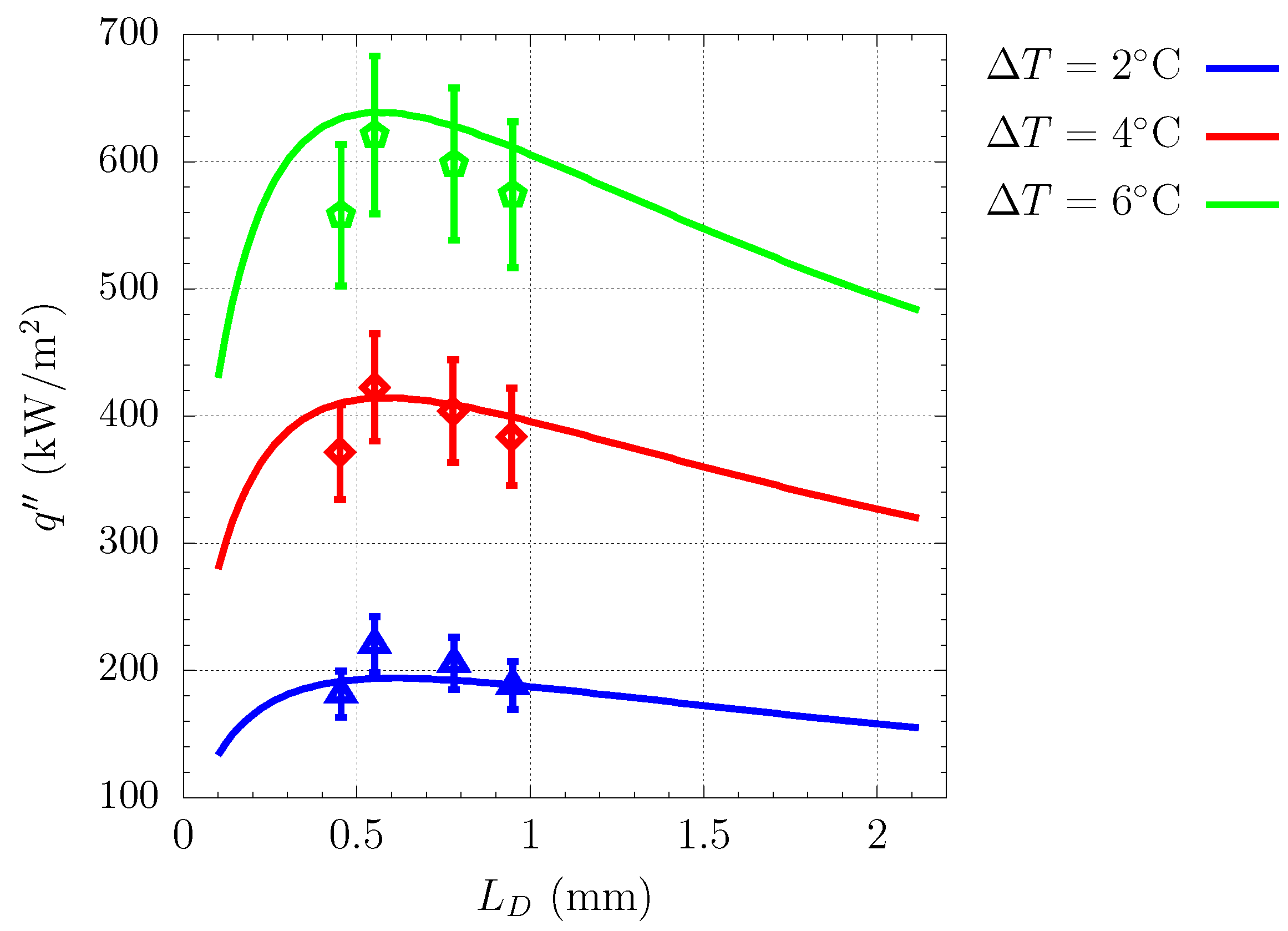
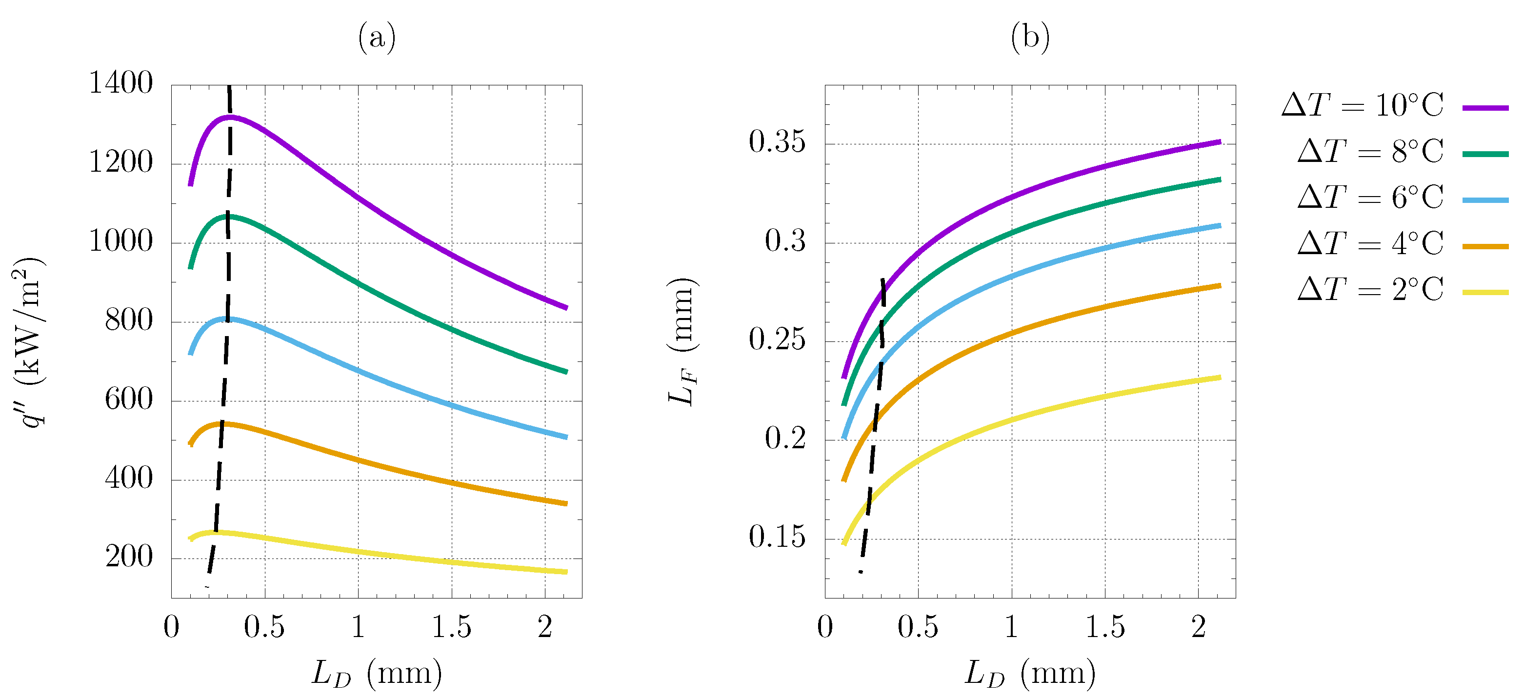
3.2. Hybrid Surface Optimization

Once the hydrophobic surface had been characterized and the numerical model validated with experimental evidences involving hybrid surfaces, the optimization of the hybrid geometry shown in Figure 1 was conducted. In particular, the hydrophobic width and the hydrophilic width giving the highest heat flux were determined. Following the experimental analysis of [5], steam condensation of water at T s = 100 was considered and the optimization was conducted at different values of the substrate subcooling, with Δ T up to 10 ° C . First, the effect of changing the hydrophobic width at fixed L F was investigated. Results for L F = 0.45 mm are reported in Figure 9 and compared with the experimental data of [5]. Note that a maximum of the global heat flux is achieved for all of the investigated subcooling. The corresponding hydrophobic width, L D 0.6 mm , weakly depends on the substrate subcooling. The numerical results were compared with the experimental data of [5], showing a good agreement. Indeed, the optimum configuration is correctly predicted and the computed heat fluxes fall inside the error bars of the experimental measurements.
The combined effect of changing both L D and L F was also investigated. If the flooding phenomenon was not considered, we would find that the best configuration is always given by tiny hydrophilic stripes with L F 0. In order to define a threshold for L F , the critical hydrophilic width was introduced as the width L F of a stripes of length H = 2 R , that has to drain the critical flooding flow rate m ˙ c r , defined by Equation (25). If a smaller hydrophilic width was considered, it would be observed a sudden degradation of the hybrid surface heat transfer performances due to the flooding occurrence, with the liquid film in the hydrophilic region overrunning the hydrophilic–hydrophobic boundary. Thus, configurations with L F lower than the flooding threshold are discarded. The implemented optimization algorithm is as follows:
  • For a given substrate subcooling, the DWC specific heat flux q D was computed via Equation (5) as a function of the hydrophobic width L D ;
  • The migrating flow rate per unit length m ˙ σ was derived via Equation (26) as a function of L D and q D ;
  • The critical hydrophilic width L F was computed as a function of m ˙ σ , which in turn depends on the investigated value of L D ;
  • Once L F had been traced as a function of L D , the FWC specific heat flux q F was computed via Equation (29) and combined with q D in order to estimate the global heat flux of the hybrid surface;
  • The best configuration for a given substrate subcooling was identified as the one corresponding to the maximum global heat flux.
Figure 10a shows the numerical results, obtained from the optimization of the hybrid geometry: the best configuration, which corresponds to the maximum specific heat flux q , is identified at different substrate subcoolings by a dashed line. The hydrophilic width, computed imposing the flooding threshold, is traced as a function of L D in Figure 10b: as expected, higher L F are required if the substrate subcooling increases, since both the migrating flow rate m ˙ σ and the condensate flow rate m ˙ c , which concur to define the threshold value m ˙ c r , increase with Δ T . It can be observed that when the combined optimization of L F and L D is performed, the heat transfer can be further enhanced of about the 30%, if compared to the optimal configuration found in [5], and that the optimal value of the hydrophobic width depends on the substrate subcooling. In particular, L D increases with Δ T and converges to L D 0.3 mm for a sufficiently high subcooling. On the other hand, values of the critical hydrophilic width always lower that 0.3 mm are observed in the investigated range of Δ T . It was not possible to compare the computed flooding threshold with experimental data. However, the critical width L F , computed as a function of L D and Δ T , are always lower than the corresponding hydrophilic width investigated in [5] at the same L D and Δ T , where the occurrence of flooding was not reported. Comparing Figure 10a with Figure 7 proves that, if the hybrid surface geometry is properly designed, the heat flux of the standard hydrophobic surface can be augmented of the 28% for Δ T = 7 ° C and up to 45% for Δ T = 2 ° C .

4. Conclusions

An improved model was presented for steam condensation over a hybrid hydrophobic–hydrophilic surface. Compared to the existing probability-based model [19,20], an updated correlation for the small size distribution, derived assuming that the sweeping time depends on the drop size [21,22], was used. The updated film theory models the liquid layer as a rivulet and includes both the mass exchange through hydrophobic–hydrophilic boundary and the flooding occurrence, while a film of uniform thickness was assumed to cover the hydrophilic region in the analysis of [24]. In particular, the implementation of the flooding threshold provides a criterion to discard configurations that would be retained by a standard modelization of the liquid film. The numerical model and its physical consistency were validated with the experimental data in [5]: the experimental heat flux was successfully predicted by the combined dropwise–filmwise condensation model over a wide range of cases; the imposed thermal conductivity of the SAM coating (treated as a model parameter since it was not provided in [5]), is consistent with the available data [26] as well as the predicted nucleation density, which falls in the typical range. Then, the geometry optimization of a circular test section composed of alternate hydrophobic–hydrophilic vertical stripes was conducted. The implementation of effects such as the flow rate exchanged at the hydrophobic–hydrophilic boundary and the flooding threshold allowed to investigate the combined effect of changing both the hydrophobic width and the hydrophilic. It was concluded that, compared to the optimal configuration experimentally found in [5], the exchanged heat flux can be further improved by about 30% over the whole range of the investigated subcooling.
Thus, it was demonstrated that probability-based models for DWC combined with the film theory represent a powerful tool, coupled to the experimental campaigns, for the design of hybrid hydrophobic–hydrophilic surfaces and, compared to individual-based models, which go into the details of the condensation process and provide the statistical information required for a simplified modelization, have the advantage of reducing computational costs. Indeed, the present modelization is intrinsically characterized by low computational costs, similar to the one of a standard probability-based model, while an individual-based modelization would not allow to investigate a large number of configurations, since it traces the evolution of the whole population, composed by millions of droplets. In perspective, such an approach represents a fast and reliable method to obtain preliminary but still accurate indications before eventually testing new hybrid geometries via dedicated experiments.
Another possible application may be the characterization of hydrophobic surfaces in terms of the density of the nucleating sites via the PBMs. The effect of the coating thickness, which is considered in the present model, was included in [19,20] via the implementation of the modified Rose correlation, while the effect of the surface topography, not considered in the PBMs, was modeled in [27], introducing the fractal dimension of the surface. The film model may be also refined, eventually including the liquid inertia, in order to investigate complex configurations such as the V-shaped channel design in [10]. Further improvements may involve the implementation of the nano-structured superhydrophobic surfaces: a dedicated modelization of the coating layer behavior, such as the one of [8], is required to provide the actual liquid–solid contact angle as a function of the wetting (Cassie or Wenzel) state; an updated correlation for the droplet size distribution, to be obtained via large IBM simulations, is required to account for the additional mechanism given by the coalescence-induced droplet jumping, which adds to the gravity-driven motion and further enhances the surface renewal [6].

Author Contributions

Conceptualization, G.C.; Software, N.S.; Investigation, N.S.; Writing—original draft, N.S.; Writing—review & editing, G.C.; Supervision, G.C. All authors have read and agreed to the published version of the manuscript.

Funding

The financial support of the DPIA of University of Udine under the strategic program “PSD-ESPERT” is gratefully acknowledged.

Data Availability Statement

Dataset available on request from the authors.

Conflicts of Interest

The authors declare no conflicts of interest.

Glossary

The following abbreviations are used in this manuscript:
Abbreviations
PBMProbability-based model
IBMIndividual-based model
DWCDropwise condensation
FWCFilmwise condensation
SAMSelf-assembled monolayer
Nomenclature
Greek symbols
δ rivulet thickness m
δ c coating thickness m
Ψ availability J
θ static contact angle rad
λ thermal conductivity W m 1 K 1
μ dynamic viscosity Pa · s
ρ density kg m 3
ρ n nucleation density m 2
σ l v surface tension N m 1
τ sweeping time s
Other symbols
ggravity acceleration m s 2
Gdroplet growth rate m s 1
h l v latent heat of vaporization J kg 1
l c capillary length m
L D hydrophobic width m
L F hydrophilic width m
m ˙ liquid mass flow rate kg s 1
n r small drop size distribution m 3
N r large drop size distribution m 3
qheat flux W
q specific heat flux W m 2
rdroplet radius m
r 0 critical nucleation radius m
r m a x   departure radius m
R g specific gas constant J kg 1 K 1
ttime s
T s saturation temperature °C
T w solid wall temperature °C
y   downhill coordinate m
Subscripts
Ddropwise
ecoalescence
Ffilmwise
nnucleation
lliquid
vvapor

References

  1. Parin, R.; Martucci, A.; Sturaro, M.; Bortolin, S.; Bersani, M.; Carraro, F.; Del Col, D. Nano-structured aluminum surfaces for dropwise condensation. Surf. Coatings Technol. 2018, 348, 1–12. [Google Scholar] [CrossRef]
  2. Alwazzan, M.; Egab, K.; Peng, B.; Khan, J.; Li, C. Condensation on hybrid-patterned copper tubes (I): Characterization of condensation heat transfer. Int. J. Heat Mass Transf. 2017, 112, 991–1004. [Google Scholar] [CrossRef]
  3. Zhang, B.J.; Kuok, C.; Kim, K.J.; Hwang, T.; Yoon, H. Dropwise steam condensation on various hydrophobic surfaces: Polyphenylene sulfide (PPS), polytetrafluoroethylene (PTFE), and self-assembled micro/nano silver (SAMS). Int. J. Heat Mass Transf. 2015, 89, 353–358. [Google Scholar] [CrossRef]
  4. Pang, G.; Dale, J.D.; Kwok, D.Y. An integrated study of dropwise condensation heat transfer on self-assembled organic surfaces through Fourier transform infra-red spectroscopy and ellipsometry. Int. J. Heat Mass Transf. 2005, 48, 307–316. [Google Scholar] [CrossRef]
  5. Peng, B.; Ma, X.; Lan, Z.; Xu, W.; Wen, R. Experimental investigation on steam condensation heat transfer enhancement with vertically patterned hydrophobic-hydrophilic hybrid surfaces. Int. J. Heat Mass Transf. 2015, 83, 27–38. [Google Scholar] [CrossRef]
  6. Stevens, K.A.; Crockett, J.; Maynes, D.; Iverson, B.D. Simulation of Drop-Size Distribution during Dropwise and Jumping Drop Condensation on a Vertical Surface: Implications for Heat Transfer Modeling. Langmuir 2019, 35, 12858–12875. [Google Scholar] [CrossRef]
  7. Subramanian, R.S.; Moumen, N.; Mc Laughlin, J.B. Motion of a drop on a solid surface due to a wettability gradient. Langmuir 2005, 21, 11844–11849. [Google Scholar] [CrossRef]
  8. Xie, J.; Xu, J.; Shang, W.; Zhang, K. Dropwise condensation on superhydrophobic nanostructure surface, part II: Mathematical model. Int. J. Heat Mass Transf. 2018, 127, 1170–1187. [Google Scholar] [CrossRef]
  9. Alwazzan, M.; Egab, K.; Peng, B.; Khan, J.; Li, C. Condensation on hybrid-patterned copper tubes (II): Visualization study of droplet dynamics. Int. J. Heat Mass Transf. 2017, 112, 950–958. [Google Scholar] [CrossRef]
  10. Yang, K.S.; Lin, K.H.; Tu, C.W.; He, Y.Z.; Wang, C.C. Experimental investigation of moist air condensation on hydrophilic, hydrophobic, superhydrophilic, and hybrid hydrophobic-hydrophilic surfaces. Int. J. Heat Mass Transf. 2017, 115, 1032–1041. [Google Scholar] [CrossRef]
  11. Croce, G.; Suzzi, N. Numerical simulation of dropwise condensation of steam over hybrid Surfaces via new non-dimensional heat transfer model. Fluids 2023, 8, 300. [Google Scholar] [CrossRef]
  12. Tancon, M.; Bortolin, S.; Del Col, D. Modeling of growth and dynamics of droplets during dropwise condensation of steam. Int. J. Heat Mass Transf. 2024, 222, 125109. [Google Scholar]
  13. Suzzi, N.; Croce, G. Numerical simulation of dropwise condensation over hydrophobic surfaces using vapor-diffusion model. Appl. Therm. Eng. 2022, 214, 118806. [Google Scholar] [CrossRef]
  14. Suzzi, N.; Croce, G.; D’Agaro, P. Numerical prediction of dropwise condensation performances over hybrid surfaces, under the action of gravity and vapor shear. In Proceedings of the ASME 18th International Conference on Nanochannels, Microchannels, and Minichannels, ICNMM, Online, 13–15 July 2020; p. ICNMM2020-1075. [Google Scholar]
  15. Croce, G.; D’Agaro, P.; Suzzi, N. Optimization of hybrid hydrophilic-hydrophobic surfaces for dropwise condensation enhancement. In Proceedings of the ASME 17th International Conference on Nanochannels, Microchannels, and Minichannels, ICNMM, St. John’s, NL, Canada, 23–26 June 2019; p. ICNMM2019-4291. [Google Scholar]
  16. Le Fevre, E.J.; Rose, J.W. A theory of heat transfer by dropwise condensation. In Proceedings of the 3rd International Heat Transfer Conference, Chicago, IL, USA, 7–12 August 1966; pp. 362–375. [Google Scholar]
  17. Kim, S.; Kim, K.J. Dropwise Condensation Modeling Suitable for Superhydrophobic Surfaces. ASME J. Heat Transf. 2011, 133, 081502. [Google Scholar] [CrossRef]
  18. Miljkovic, N.; Enright, R.; Wang, E.N. Modeling and Optimization of Superhydrophobic Condensation. ASME J. Heat Mass Transf. 2013, 135, 111004. [Google Scholar] [CrossRef]
  19. Liu, X.; Cheng, P. Dropwise condensation theory revisited: Part I. Droplet nucleation radius. Int. J. Heat Mass Transf. 2015, 83, 833–841. [Google Scholar] [CrossRef]
  20. Liu, X.; Cheng, P. Dropwise condensation theory revisited Part II. Droplet nucleation density and condensation heat flux. Int. J. Heat Mass Transf. 2015, 83, 842–849. [Google Scholar] [CrossRef]
  21. Lethuillier, J.; Lavieille, P.; Topin, F.; Miscevic, M. About Phenomenology and Modeling of Dropwise Condensation. In The Surface Wettability Effect on Phase Change; Springer: Cham, Switzerland, 2022; pp. 69–104. [Google Scholar]
  22. Suzzi, N.; Croce, G. Effect of hydrophobic coating on optimization of dropwise condensation of steam on hybrid surfaces. J. Phys. Conf. Ser. 2024; in press. [Google Scholar]
  23. Rose, J.W. Further aspects of dropwise condensation theory. Int. J. Heat Nad Mass Transf. 1976, 19, 1363–1370. [Google Scholar] [CrossRef]
  24. Peng, B.; Ma, X.; Lan, Z.; Xu, W.; Wen, R. Analysis of condensation heat transfer enhancement with dropwise-filmwise hybrid surface: Droplet sizes effect. Int. J. Heat Mass Transf. 2014, 77, 785–794. [Google Scholar] [CrossRef]
  25. Nusselt, W. Die Oberflachenkondensation des Wasserdampfes. Z. Ver. Dtsch. Ingenieure 1916, 60, 541–546, 569–575. [Google Scholar]
  26. Song, L.; Zhang, Y.; Yang, W.; Tan, J.; Cheng, L. Molecular Structure Effect of a Self-Assembled Monolayer on Thermal Resistance across an Interface. Polymers 2021, 13, 3732. [Google Scholar] [CrossRef]
  27. Mu, C.; Pang, J.; Lu, Q.; Liu, T. Effects of surface topography of material on nucleation site density of dropwise condensation. Chem. Eng. Sci. 2008, 63, 874–880. [Google Scholar] [CrossRef]
Figure 1. Hybrid surface experimentally investigated in [5]: left, vertical disc composed of alternate hydrophobic and hydrophilic stripes; right, droplet migration from the hydrophobic domain, characterized by DWC regime, to the hydrophilic domain.
Energies 17 02742 g001
Figure 2. Comparison between the updated small drop correlation, Equations (11) and (12), and the theoretical correlation of [17]: negligible coating thermal resistance, r e = 9.14 × 10 3 μ m (a); δ c / λ c = 10 7 m 2 K / W , r e = 2.60 × 10 2 μ m (b). Water, T s = 100 ° C , Δ T = 6 , θ = 120 , r m a x = 1.25 mm .
Energies 17 02742 g002
Figure 3. Nucleation radius as a function of the substrate subcooling Δ T = T s T w and of the coating thermal resistance δ c / λ c . The dashed line denotes the critical coalescence radius, Equation (4). Water at saturation temperature T s = 100 ° C , θ = 120 .
Energies 17 02742 g003
Figure 4. Specific heat flux as a function of the droplet radius and of the coating thermal resistance: the dashed line denotes the heat flux of a newly nucleated drop, characterized by r = r n (a). Drop size distribution at different values of the coating thermal resistance: the colored lines correspond to the small size distribution, Equations (11) and (12), while the dashed line corresponds to the large size distribution, Equation (6) (b). Water, T s = 100 ° C , Δ T = 6 ° C , θ = 120 , r m a x = 1.25 mm .
Energies 17 02742 g004
Figure 5. Dropwise condensation specific heat flux computed via Equation (5) for different values of the coating specific thermal resistance: effect of the substrate subcooling Δ T = T s T w , fixed maximum radius r m a x = 1.25 mm (a); effect of the maximum droplet radius r m a x , fixed subcooling Δ T = 6 ° C (b). Water, T s = 100 ° C , θ = 120 .
Energies 17 02742 g005
Figure 6. Film thickness (a) and specific heat flux (b) along a vertical plate at different values of the migrating flow rate per unit length m ˙ σ . Hydrophilic width is set to L F = 0.45 mm . Water at saturation temperature is T s = 100 ° C and substrate subcooling is set to Δ T = 6 ° C . Dashed lines provide results predicted by the standard Nusselt film theory.
Energies 17 02742 g006
Figure 7. Computed heat flux, continuous line, versus experimental data of [5], red markers, with dashed lines representing the computed contributions from the small and from the large drop population (a). Computed nucleation density as a function of substrate subcooling (b). Water, T s = 100 ° C , θ = 120 , r m a x = 1.25 mm , δ c / λ c = 3.39 × 10 7 m 2 K / W .
Energies 17 02742 g007
Figure 8. Heat flux as a function of substrate subcooling: L D = 0.78 mm , L F = 0.46 mm (a); L D = 0.55 mm , L F = 0.45 mm (b); L D = 0.96 mm , L F = 1.33 mm (c); L D = 0.93 mm , L F = 2.1 mm (d). Black lines denote numerical results, markers refer to experimental data of [5]. Water, T s = 100 ° C , θ = 120 , δ c / λ c = 3.39 × 10 7 m 2 K / W .
Energies 17 02742 g008
Figure 9. Global heat flux as a function of the hydrophobic width L D and of the substrate subcooling Δ T at a fixed hydrophilic width L F = 0.45 mm : numerical results (continuous line) versus experimental evidences of [5] (markers). Water, T s = 100 ° C , θ = 120 , δ c / λ c = 3.39 × 10 7 m 2 K / W .
Energies 17 02742 g009
Figure 10. Specific heat flux of the hybrid surface as a function of the hydrophobic width L D and of the imposed substrate subcooling Δ T (a). Corresponding critical hydrophilic width L F as a function of L D and Δ T (b). Dashed curves represent the observed optimal configuration, which gives the maximum heat flux for a given substrate subcooling. Water, T s = 100 , θ = 120 , δ c / λ c = 3.39 × 10 7 m 2 K / W .
Energies 17 02742 g010
Disclaimer/Publisher’s Note: The statements, opinions and data contained in all publications are solely those of the individual author(s) and contributor(s) and not of MDPI and/or the editor(s). MDPI and/or the editor(s) disclaim responsibility for any injury to people or property resulting from any ideas, methods, instructions or products referred to in the content.

