
Active Equalization for Lithium-Iron Battery Pack Based on Reduced-Order Solving Strategy for the Hanoi Tower Problem

Abstract
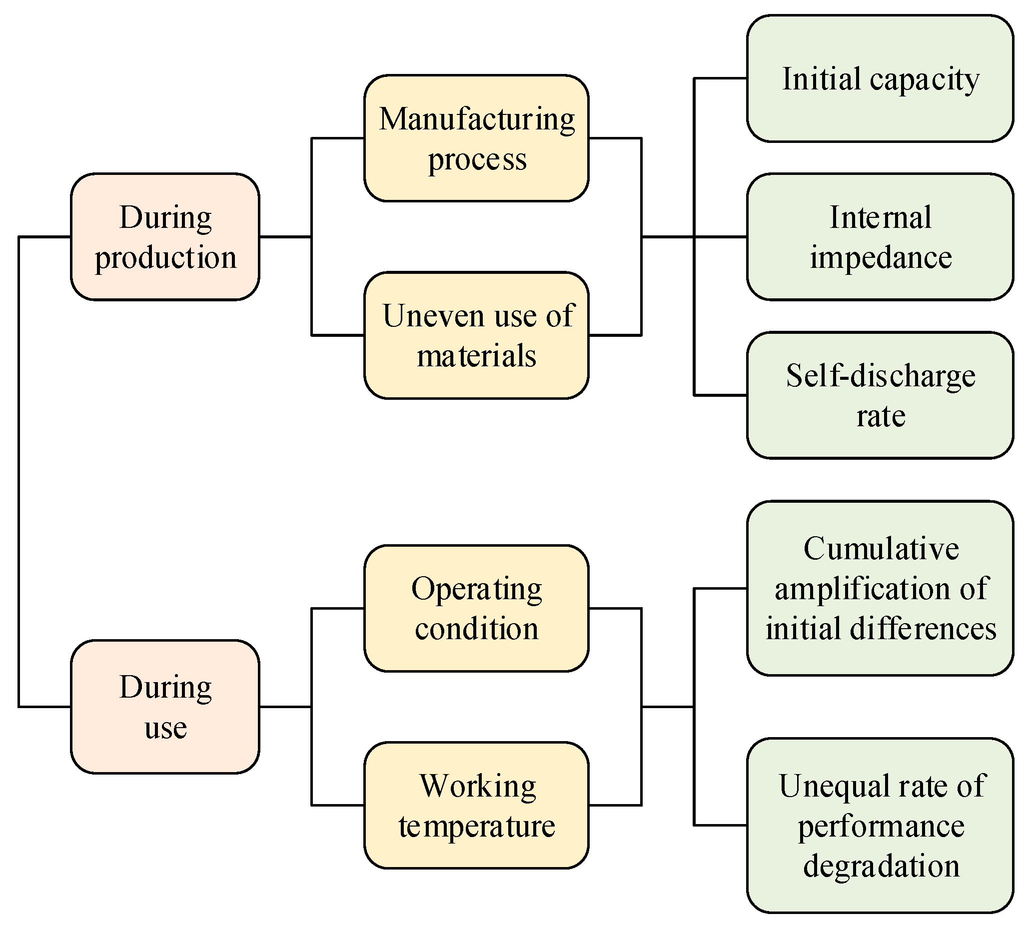
:1. Introduction
2. Active Equalizing Scheme Based on Solving the Hanoi Tower Problem
2.1. Preliminaries
- (1)
- When energy is transferred from one battery to energy storage components (such as capacitors, inductors, transformers, etc.) as an intermediate carrier of energy transfer, the equalization operation starts from the battery with the highest state of charge (SOC).
- (2)
- When energy is transferred from the intermediate carrier of energy transfer to battery cells, the energy is preferentially transferred to the battery cells with the lowest SOC.
- (1)
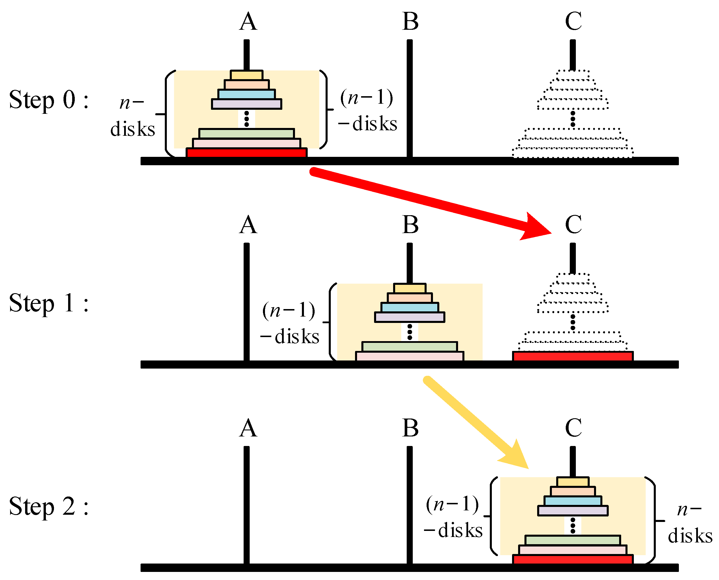
- Unbalanced energy will be distributed among three groups: Group A consists of battery cells with energy levels higher than the equilibrium target; Group B comprises intermediate energy storage components; and Group C includes battery cells with energy levels lower than the equilibrium target.
- (2)
- In the initial state, there are SOC differences between each individual cell in the battery pack. The control unit allows for the sorting operation of these differences.
- (3)
- The balancing process gives priority to balancing the battery cell with the largest state deviation in the battery pack.
- (4)
- During the balancing process, the unbalanced energy of battery cells in Group A is temporarily transferred to Group B and directed to the target Group C, ultimately causing all cells to be in a balanced state.
2.2. Balancing Strategy Based on the Solving Strategy of the Hanoi Tower Problem
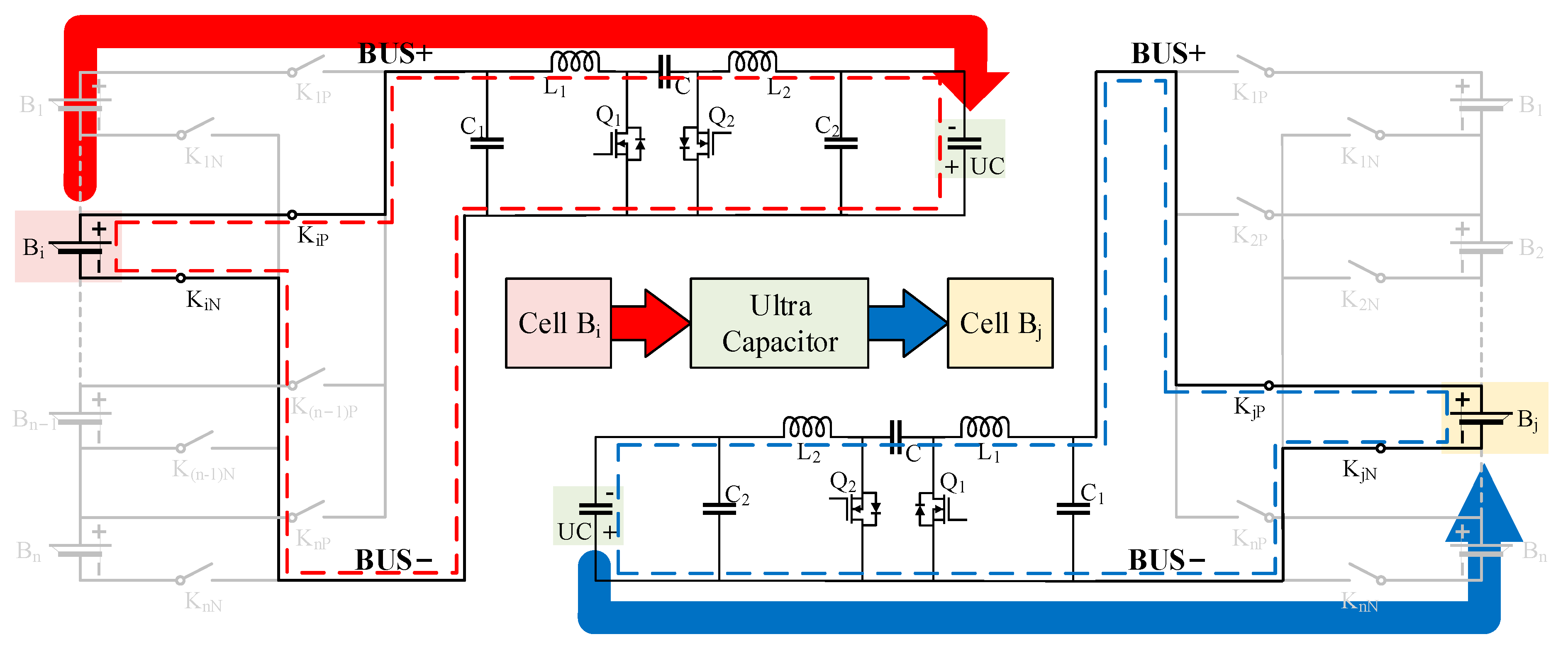
3. Balancing Topology and Its Working Principle
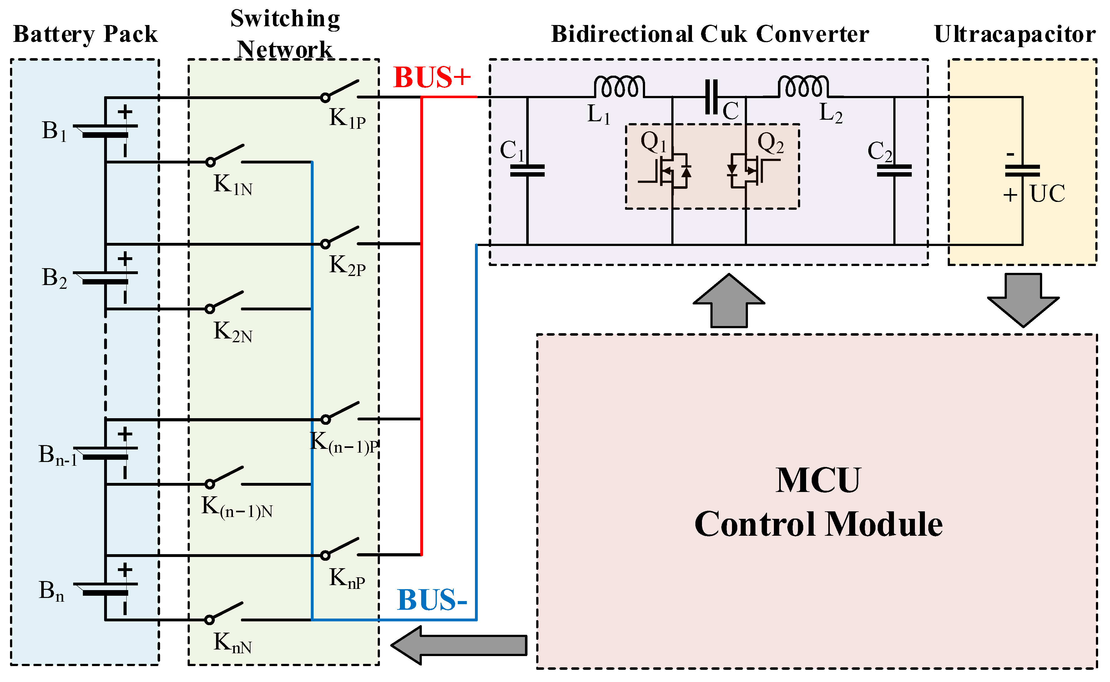
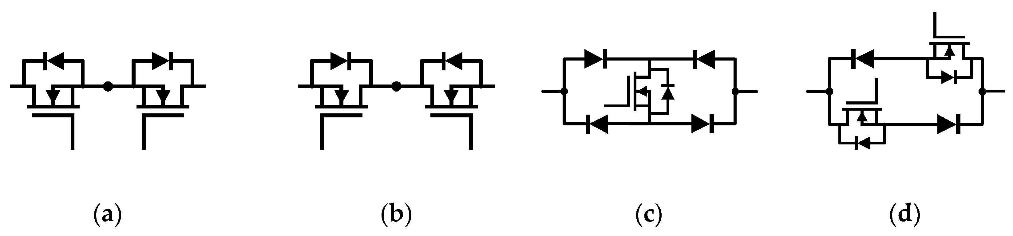
3.1. Balancing Topology Design
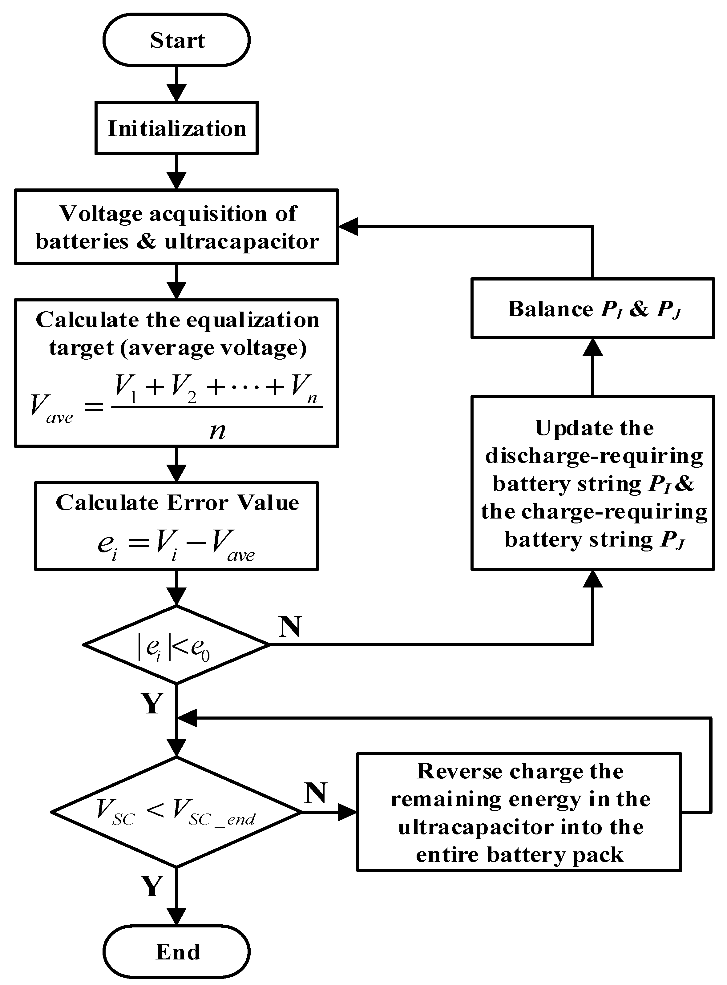
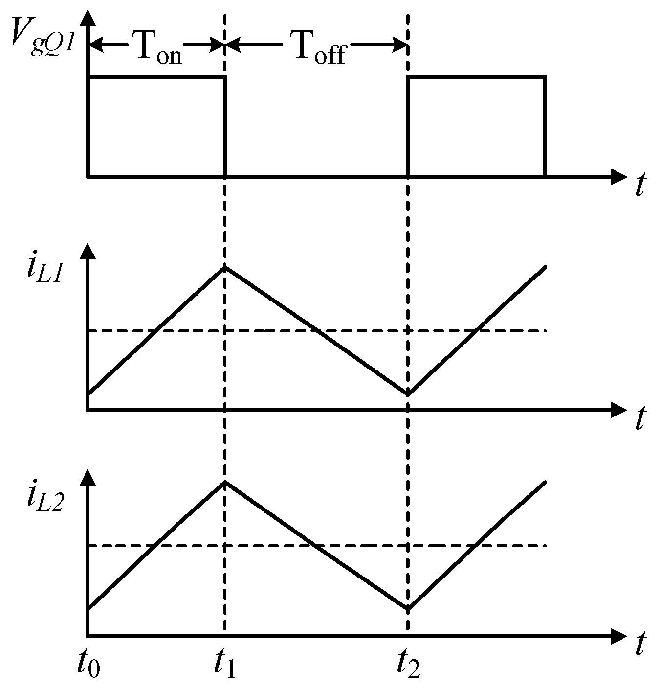
3.2. Working Principle
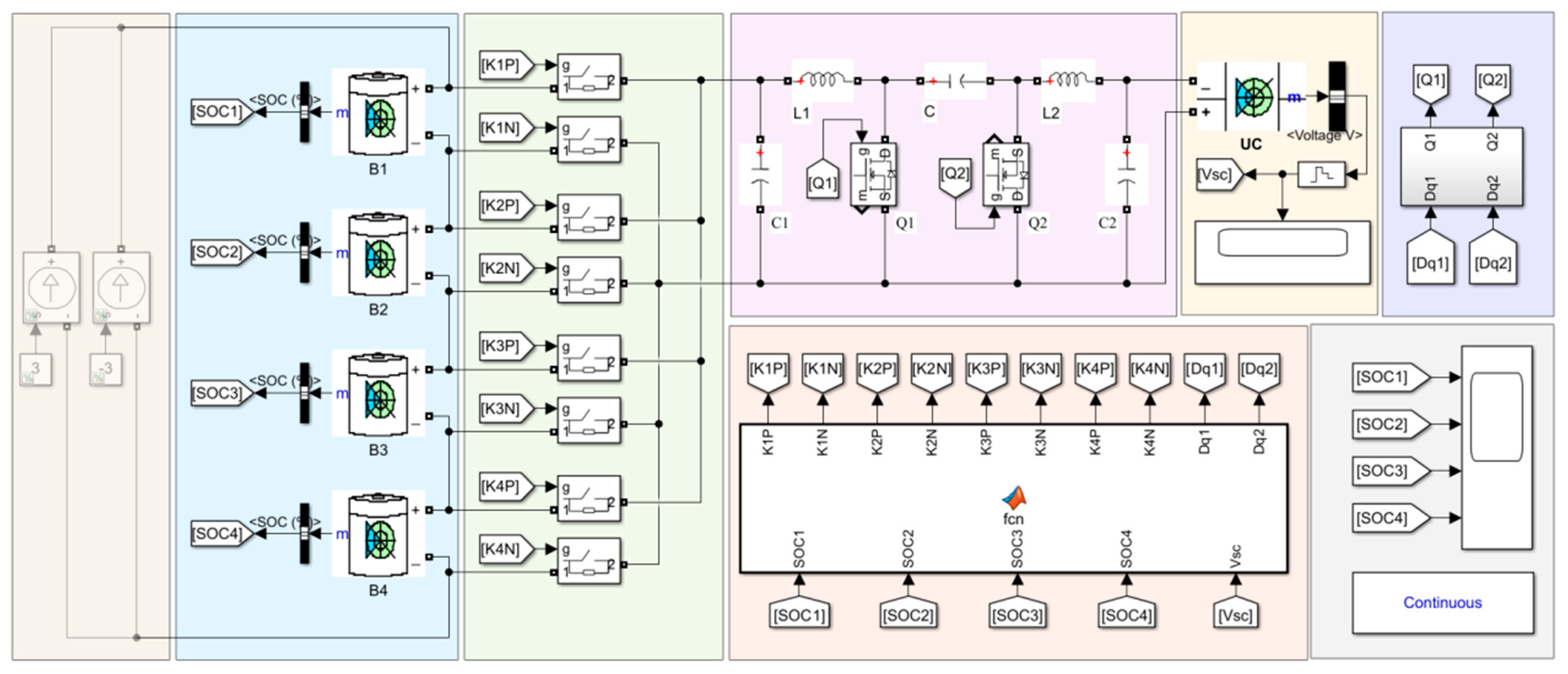
4. Validation and Discussion
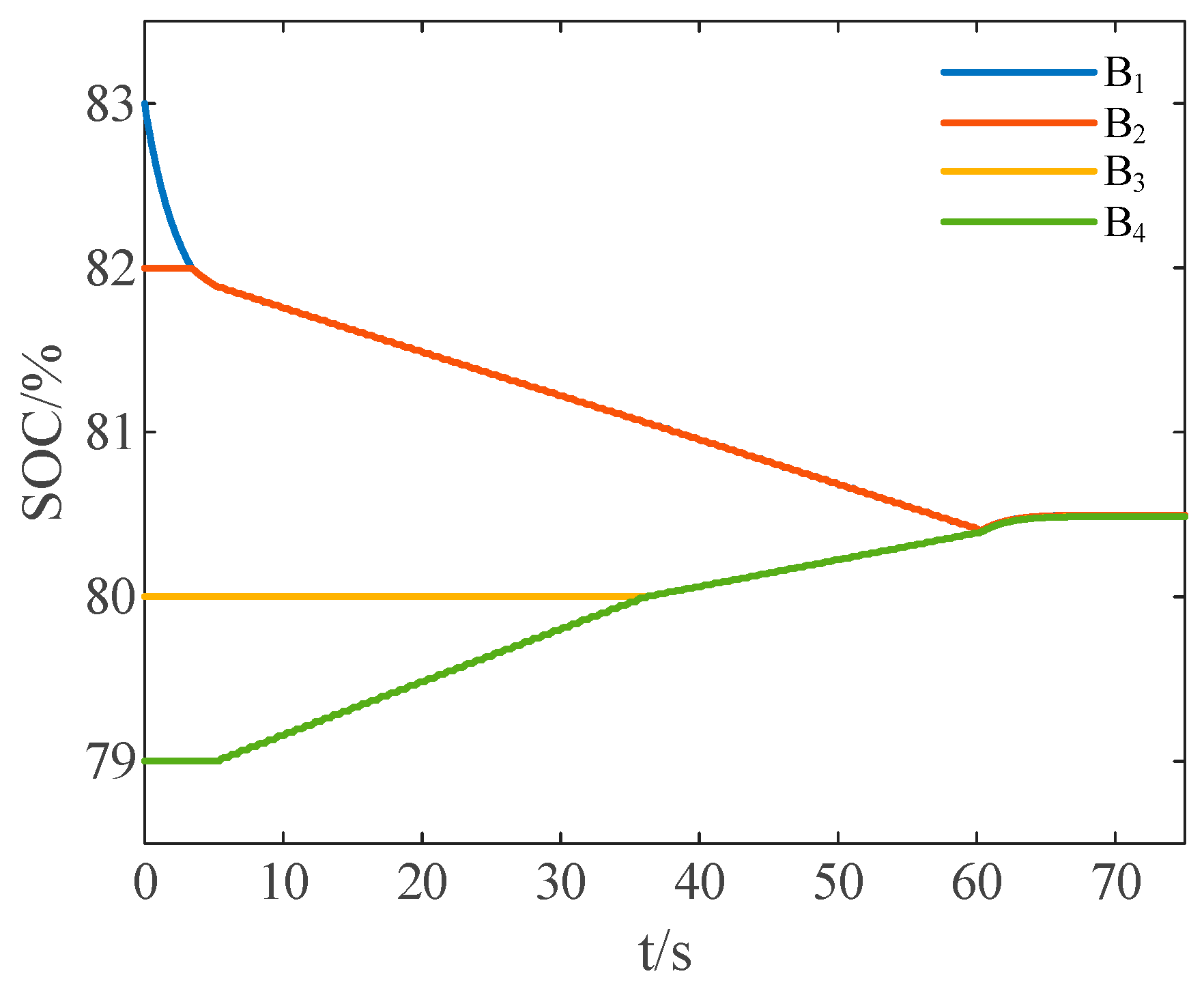
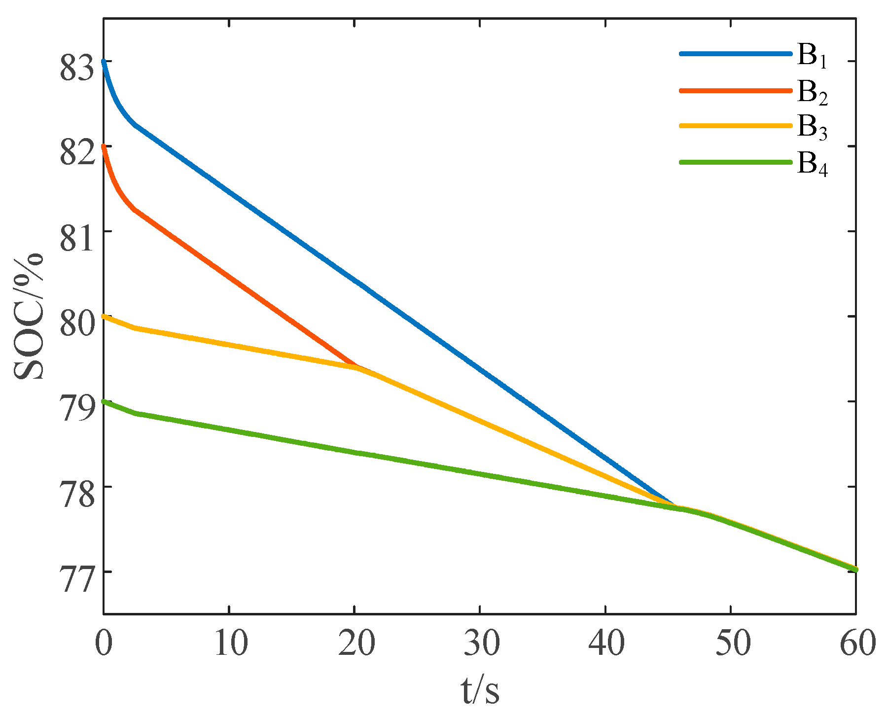
4.1. Test Scenario 1: Equalization under Rest State
4.1.1. Equalization without the Proposed Reduced-Order Strategy
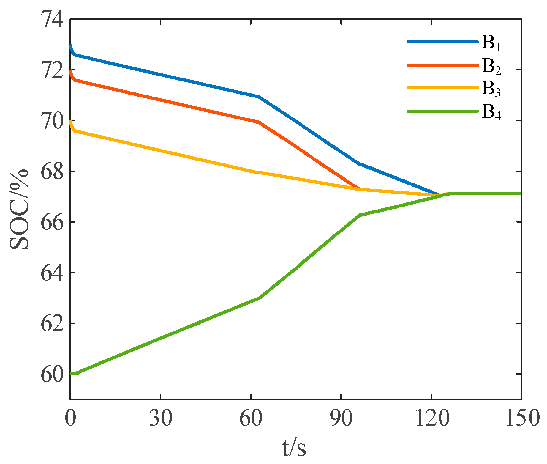
4.1.2. Equalization with the Proposed Reduced-Order Strategy
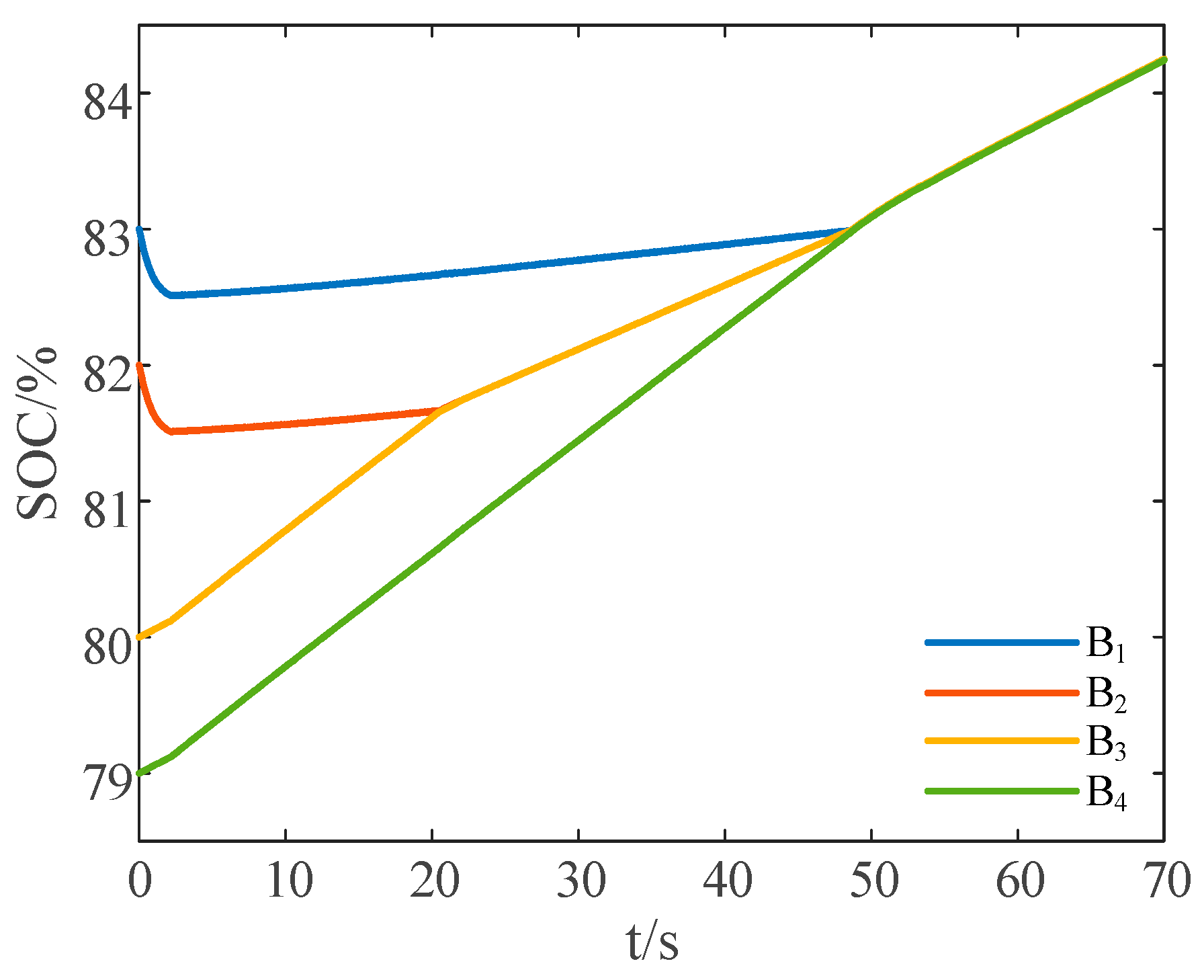
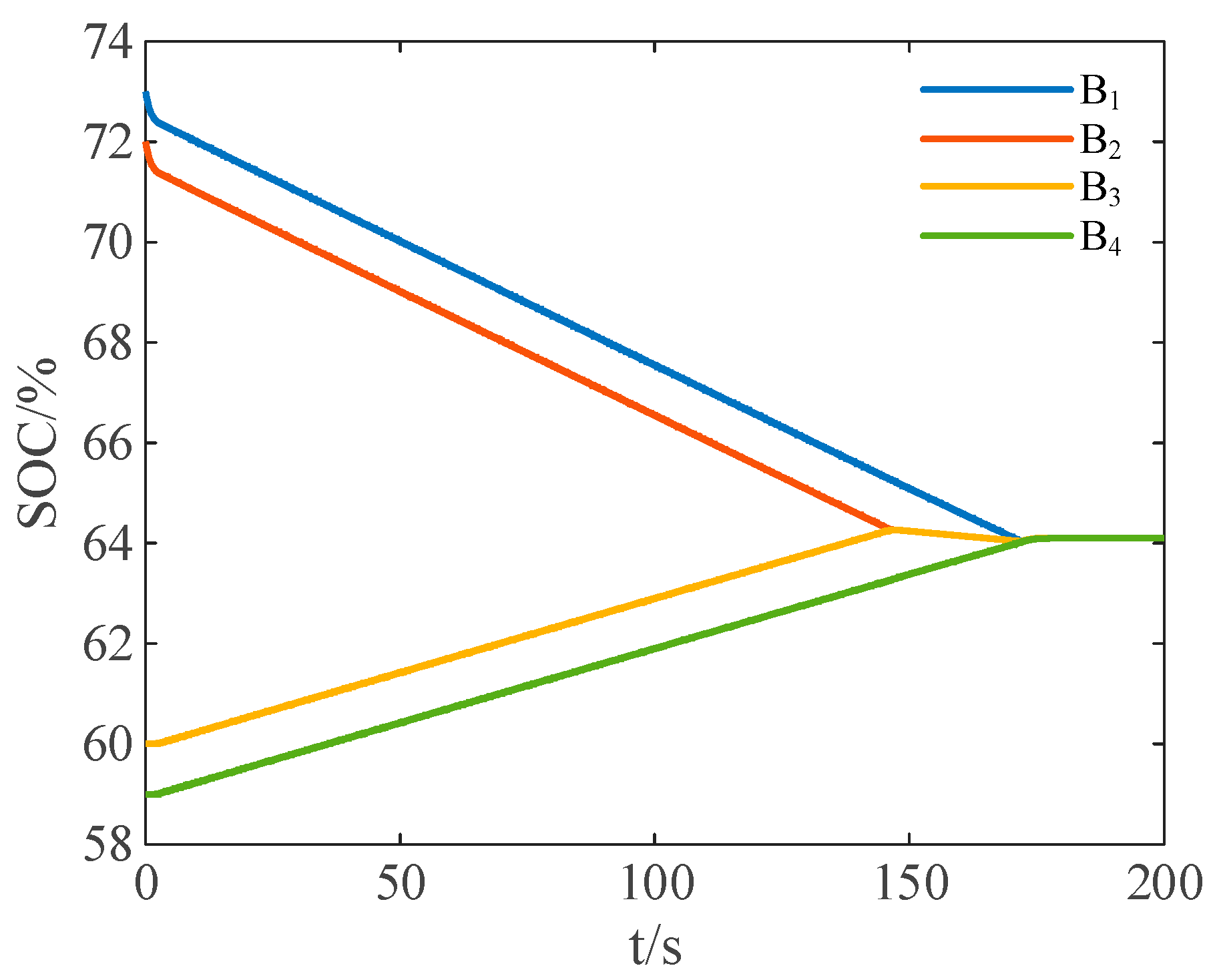
4.2. Test Scenario 2: Equalization under Charge State
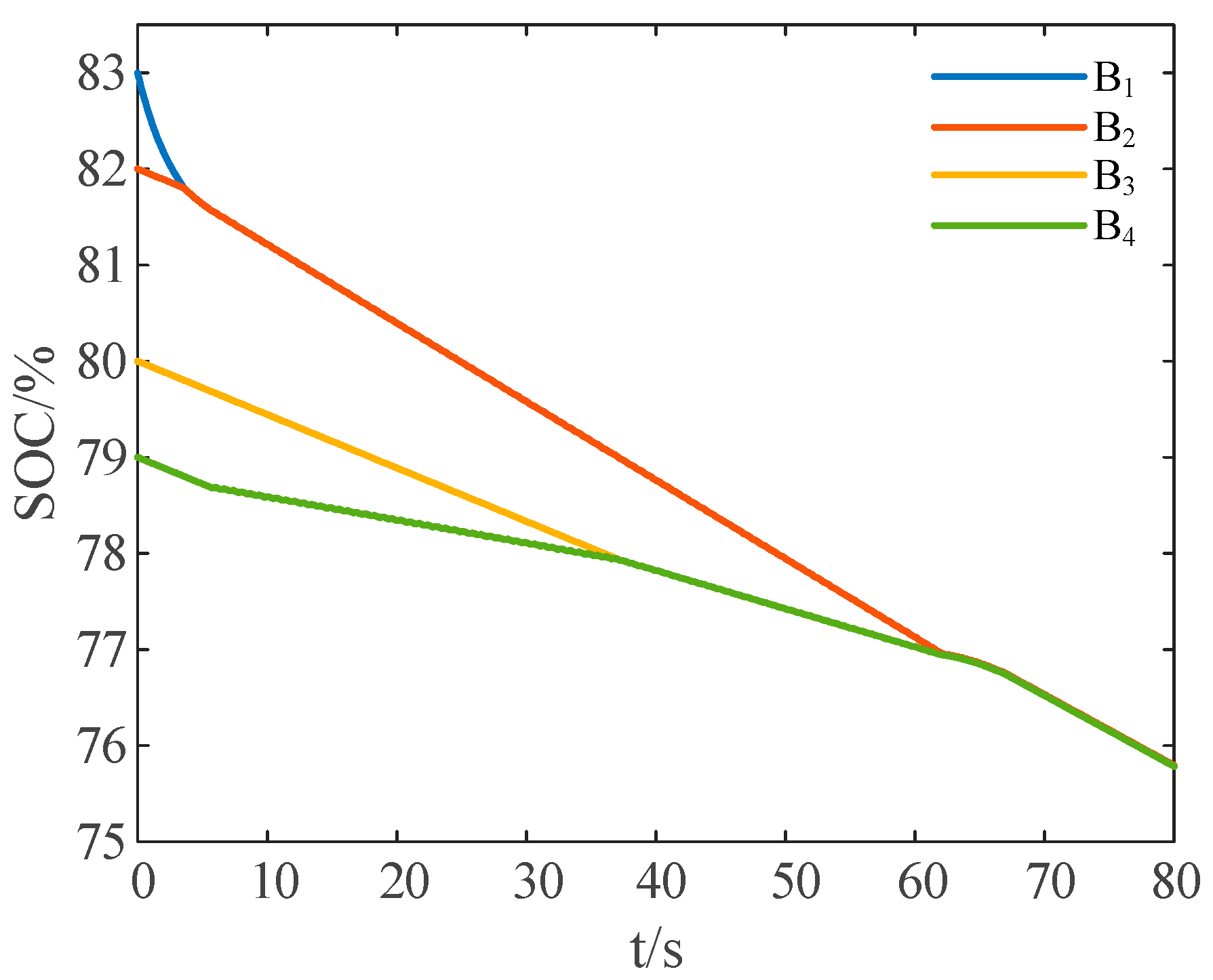
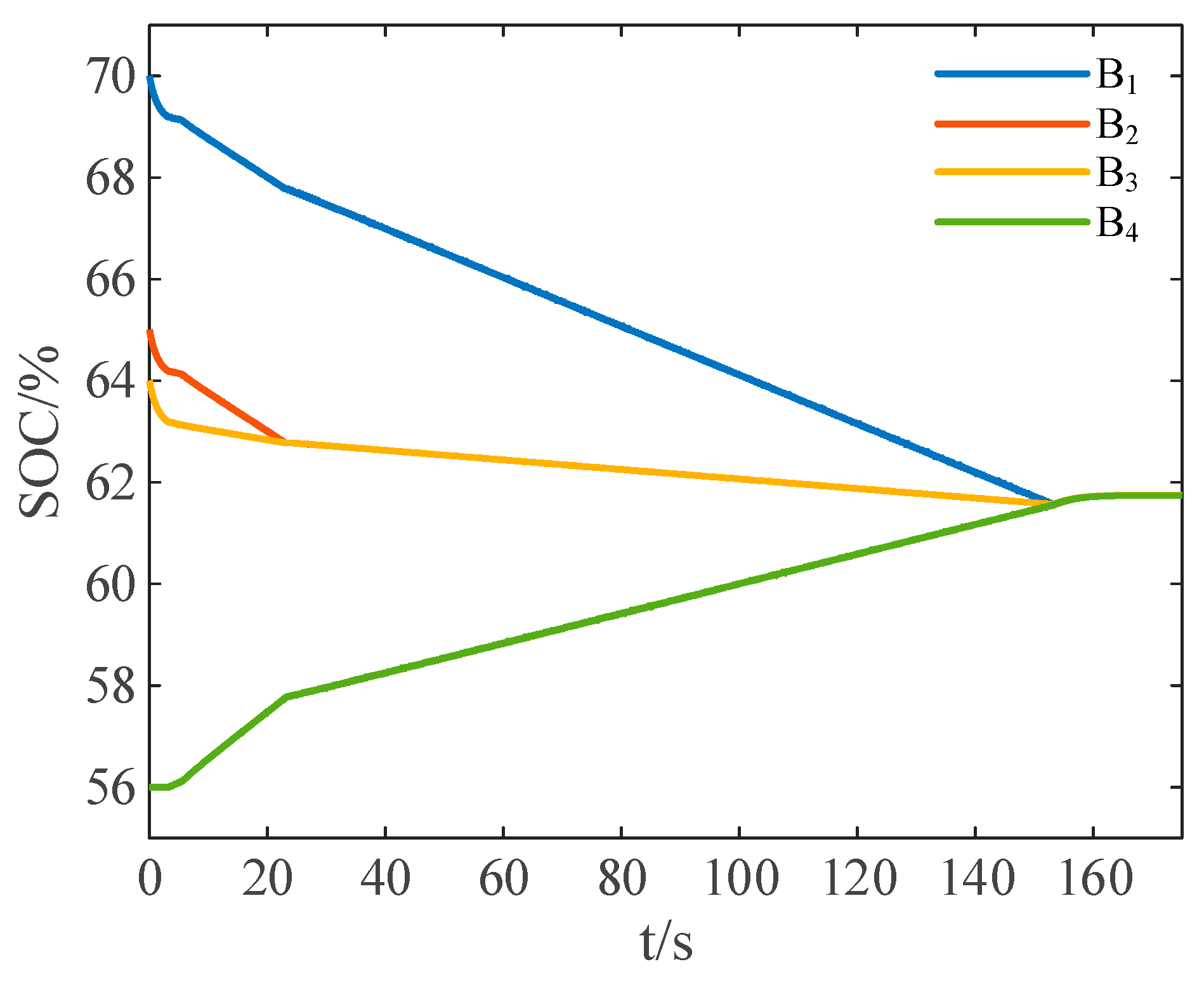
4.3. Test Scenario 3: Equalization under Discharge State
4.4. Comparison
4.5. Further Discussion
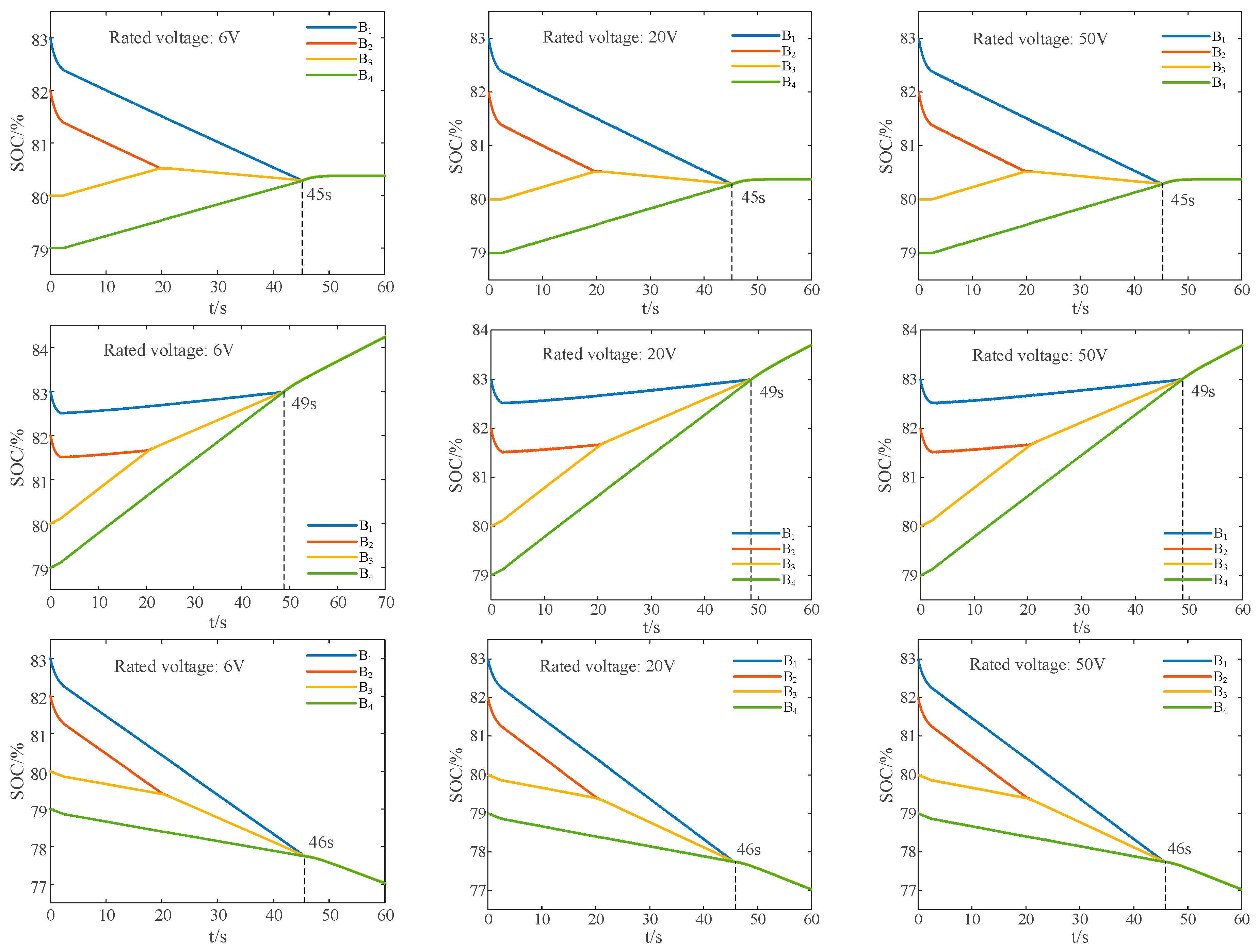
4.5.1. Feasibility in Scenarios with More Pronounced SOC Differences
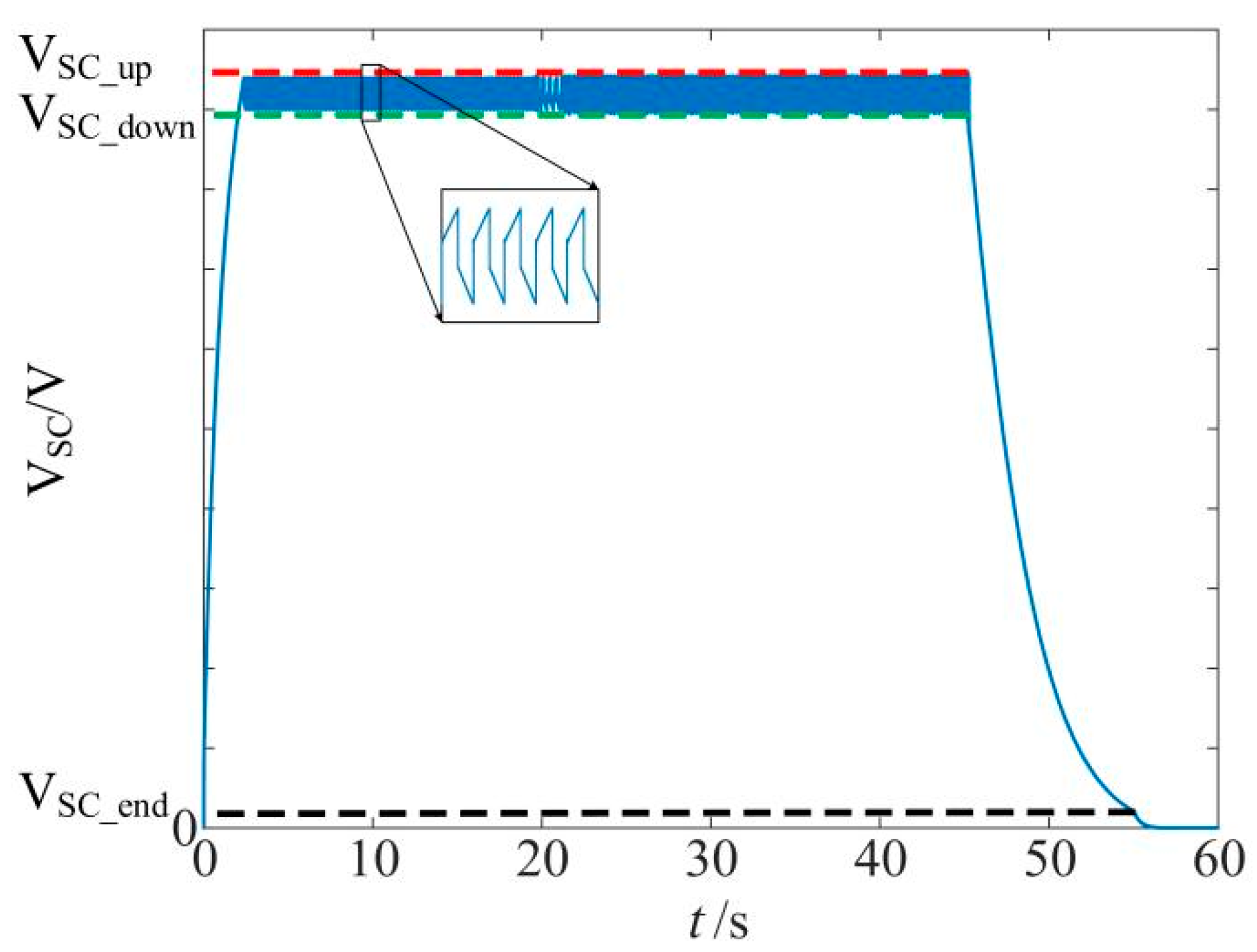
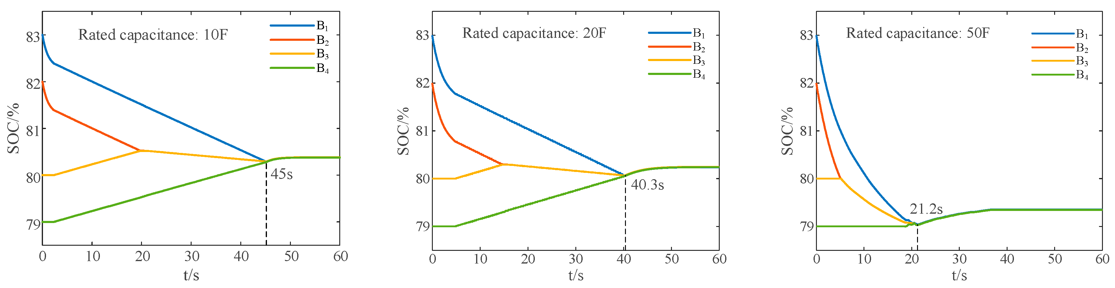
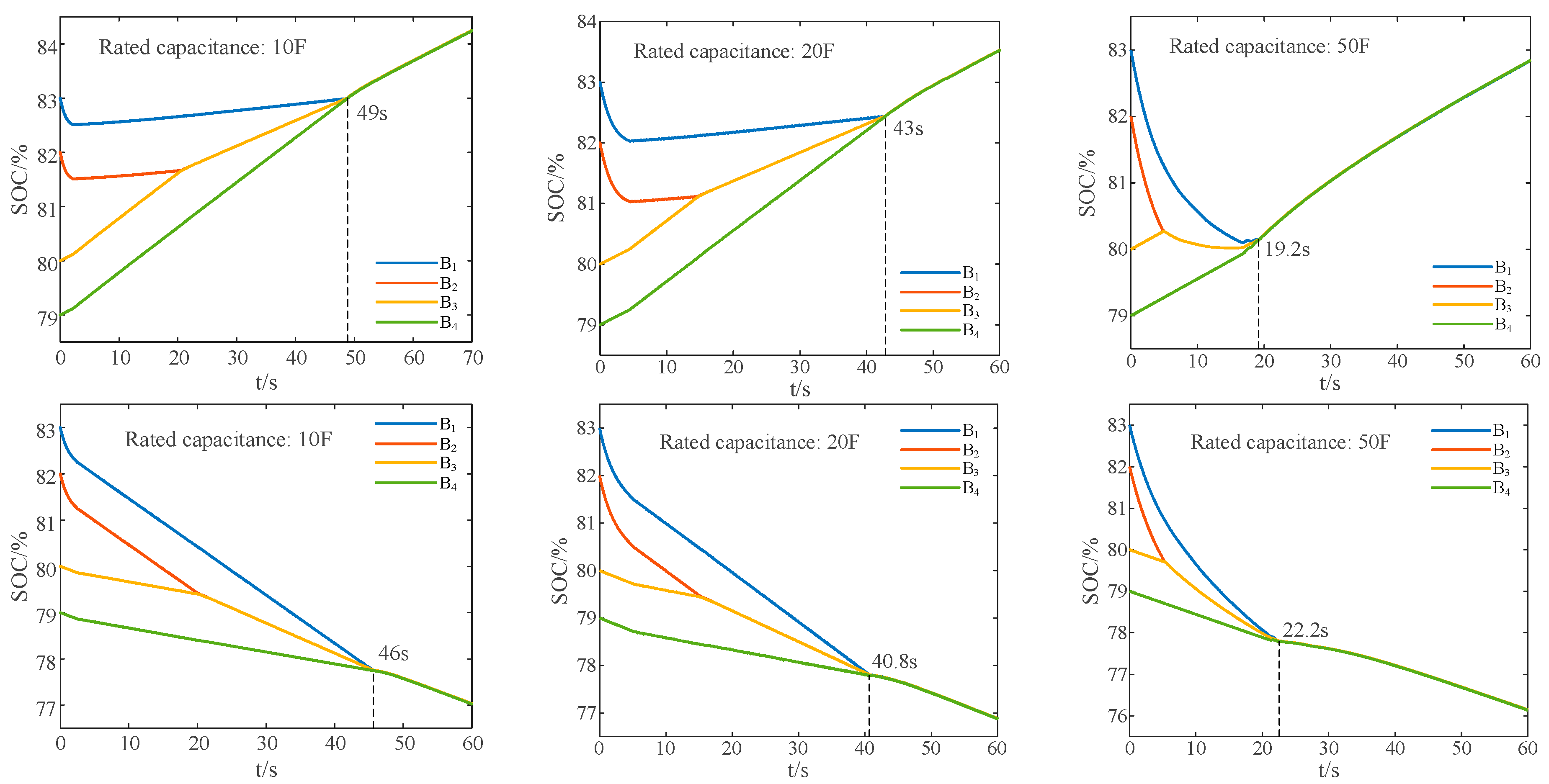
4.5.2. Discussion on the Influence of Ultracapacitor Capacity
5. Conclusions
Author Contributions
Funding
Data Availability Statement
Conflicts of Interest
References
- Zou, C.F.; Zhang, L.; Hu, X.S.; Wang, Z.P.; Wik, T.; Pecht, M. A review of fractional-order techniques applied to lithium-ion batteries, lead-acid batteries, and supercapacitors. J. Power Sources 2018, 390, 286–296. [Google Scholar] [CrossRef]
- Feng, F.; Hu, X.S.; Liu, J.F.; Lin, X.K.; Liu, B. A review of equalization strategies for series battery packs: Variables, objectives, and algorithms. Renew. Sustain. Energy Rev. 2019, 116, 109464. [Google Scholar] [CrossRef]
- Cano, Z.P.; Banham, D.; Ye, S.Y.; Hintennach, A.; Lu, J.; Fowler, M.; Chen, Z.W. Batteries and fuel cells for emerging electric vehicle markets. Nat. Energy 2018, 3, 279–289. [Google Scholar] [CrossRef]
- Wang, J.X.; Chen, L.D.; Tan, Z.F.; Du, E.; Liu, N.; Ma, J.; Sun, M.Y.; Li, C.B.; Song, J.; Lu, X.; et al. Inherent spatiotemporal uncertainty of renewable power in China. Nat. Commun. 2023, 14, 5379. [Google Scholar] [CrossRef]
- Andwari, A.M.; Pesiridis, A.; Rajoo, S.; Martinez-Botas, R.; Esfahanian, V. A review of battery electric vehicle technology and readiness levels. Renew. Sustain. Energy Rev. 2017, 78, 414–430. [Google Scholar] [CrossRef]
- Uno, M.; Yashiro, K.; Hasegawa, K. Modularized Equalization Architecture With Voltage Multiplier-Based Cell Equalizer and Switchless Switched Capacitor Converter-Based Module Equalizer for Series-Connected Electric Double-Layer Capacitors. IEEE Trans. Power Electron. 2019, 34, 6356–6368. [Google Scholar] [CrossRef]
- Peng, F.X.; Wang, H.Y.; Yu, L. Analysis and Design Considerations of Efficiency Enhanced Hierarchical Battery Equalizer Based on Bipolar CCM Buck-Boost Units. IEEE Trans. Ind. Electron. 2019, 55, 4053–4063. [Google Scholar] [CrossRef]
- Cai, M.Y.; Zhang, E.; Lin, J.; Wang, K.L.; Jiang, K.; Zhou, M. Review on Balancing Topology of Lithium-ion Battery Pack. Proc. CSEE 2021, 41, 5294–5311. [Google Scholar]
- Gallardo-Lozano, J.; Romero-Cadaval, E.; Milanes-Montero, M.I.; Guerrero-Martinez, M.A. A novel active battery equalization control with on-line unhealthy cell detection and cell change decision. J. Power Sources 2015, 299, 356–370. [Google Scholar] [CrossRef]
- Gallardo-Lozano, J.; Romero-Cadaval, E.; Milanes-Montero, M.I.; Guerrero-Martinez, M.A. Battery equalization active methods. J. Power Sources 2014, 246, 934–949. [Google Scholar] [CrossRef]
- Ghaeminezhad, N.; Ouyang, Q.; Hu, X.S.; Xu, G.T.; Wang, Z.S. Active cell equalization topologies analysis for battery packs: A systematic review. IEEE Trans. Power Electron. 2021, 36, 9119–9135. [Google Scholar] [CrossRef]
- Kim, M.Y.; Kim, C.H.; Kim, J.H.; Moon, G.W. A chain structure of switched capacitor for improved cell balancing speed of lithium-ion batteries. IEEE Trans. Ind. Electron. 2014, 61, 3989–3999. [Google Scholar] [CrossRef]
- Shang, Y.L.; Zhang, C.H.; Cui, N.X.; Mi, C.C. A delta-structured switched-capacitor equalizer for series-connected battery strings. IEEE Trans. Power Electron. 2019, 34, 452–461. [Google Scholar]
- Shang, Y.L.; Zhang, Q.; Cui, N.X.; Duan, B.; Zhang, C.H. An optimized mesh-structured switched-capacitor equalizer for lithium-ion battery strings. IEEE Trans. Transp. Electrif. 2019, 5, 252–261. [Google Scholar] [CrossRef]
- Zheng, X.X.; Liu, X.T.; He, Y.; Zeng, G.J. Active vehicle battery equalization scheme in the condition of constant-voltage/current charging and discharging. IEEE Trans. Veh. Technol. 2017, 66, 3714–3723. [Google Scholar]
- Phung, T.H.; Collet, A.; Crebier, J.C. An optimized topology for next-to-next balancing of series-connected lithium-ion cells. IEEE Trans. Power Electron. 2014, 29, 4603–4613. [Google Scholar] [CrossRef]
- Ding, X.F.; Zhang, D.H.; Cheng, J.W.; Wang, B.B.; Chai, Y.M.; Zhao, Z.H.; Xiong, R.; Luk, P.C.K. A novel active equalization topology for series-connected Lithium-ion battery packs. IEEE Trans. Ind. Appl. 2020, 56, 6892–6903. [Google Scholar] [CrossRef]
- Li, S.Q.; Mi, C.C.; Zhang, M.Y. A high-efficiency active battery-balancing circuit using multiwinding transformer. IEEE Trans. Ind. Appl. 2013, 49, 198–207. [Google Scholar] [CrossRef]
- Chen, Y.; Liu, X.F.; Cui, Y.Y.; Zou, J.M.; Yang, S.Y. A multiwinding transformer cell-to-cell active equalization method for lithium-ion batteries with reduced number of driving circuits. IEEE Trans. Power Electron. 2016, 31, 4916–4929. [Google Scholar]
- Shang, Y.L.; Cui, N.X.; Zhang, C.H. An Optimized Any-Cell-to-Any-Cell Equalizer Based on Coupled Half-bridge Converters for Series-Connected Battery Strings. IEEE Trans. Power Electron. 2019, 34, 8831–8841. [Google Scholar] [CrossRef]
- Wei, Z.Q.; Wang, H.Y.; Lu, Y.Q.; Shu, D.D.; Ning, G.D.; Fu, M.F. Bidirectional Constant Current String-to-Cell Battery Equalizer Based on L2C3 Resonant Topology. IEEE Trans. Power Electron. 2023, 38, 666–677. [Google Scholar] [CrossRef]
- Wang, L.J.; Ke, J.Y.; Zhan, M.; Tian, A.N.; Wu, T.Z.; Zhang, X.X.; Jiang, J.C. Efficient and Fast Active Equalization Method for Retired Battery Pack Using Wide Voltage Range Bidirectional Converter and DBSCAN Clustering Algorithm. IEEE Trans. Power Electron. 2022, 37, 13824–13833. [Google Scholar]
- Qi, J.; Lu, D.D.C. A preventive approach for solving battery imbalance issue by using a bidirectional multiple-input Cuk converter working in DCVM. IEEE Trans. Ind. Electron. 2017, 64, 7780–7789. [Google Scholar] [CrossRef]
- Qi, X.B.; Wang, Y.; Fang, M.Z.; Wang, H.; Wang, Y.B.; Chen, Z. A Family of Integrated Cascade Multiport Converters for Centralized Equalization Systems: Derivation, Analysis, and Verification. IEEE Trans. Power Electron. 2023, 38, 7398–7415. [Google Scholar] [CrossRef]
- Daowd, M.; Antoine, M.; Omar, N.; van den Bossche, P.; van Mierlo, J. Single Switched Capacitor Battery Balancing System Enhancements. Energies 2013, 6, 2149–2174. [Google Scholar] [CrossRef]


| Equalization Methods | Switch | Capacitor | Inductor | Transformer | Energy Flow Types | Control Difficulty | Computing Power Requirements | Balancing Speed |
|---|---|---|---|---|---|---|---|---|
| Single switched capacitor scheme [25] | n + 5 | 1 | 0 | 0 | C2C | Simple | Low | Slow |
| Single switched inductor scheme [10] | 2n | 0 | 1 | 0 | C2C | Simple | Low | Medium |
| L2C3 resonant scheme [21] | 2n + 4 | 3 | 2 | 1 | C2C/S2C | Medium | Low | Fast |
| Four-switch bidirectional converter scheme [22] | 2n + 4 | 8 | 1 | 0 | C2C/C2S/S2C/S2S | Difficult | High | Fast |
| Proposed method | 2n + 2 | 4 | 2 | 0 | C2C/C2S/S2C/S2S | Simple | Low | Fast |
Disclaimer/Publisher’s Note: The statements, opinions and data contained in all publications are solely those of the individual author(s) and contributor(s) and not of MDPI and/or the editor(s). MDPI and/or the editor(s) disclaim responsibility for any injury to people or property resulting from any ideas, methods, instructions or products referred to in the content. |
© 2024 by the authors. Licensee MDPI, Basel, Switzerland. This article is an open access article distributed under the terms and conditions of the Creative Commons Attribution (CC BY) license (https://creativecommons.org/licenses/by/4.0/).
Share and Cite
Xia, Z.; Chen, X.; Chi, X.; Zhu, B.; Zhang, L.; Huang, Y. Active Equalization for Lithium-Iron Battery Pack Based on Reduced-Order Solving Strategy for the Hanoi Tower Problem. Energies 2024, 17, 2806. https://doi.org/10.3390/en17122806
Xia Z, Chen X, Chi X, Zhu B, Zhang L, Huang Y. Active Equalization for Lithium-Iron Battery Pack Based on Reduced-Order Solving Strategy for the Hanoi Tower Problem. Energies. 2024; 17(12):2806. https://doi.org/10.3390/en17122806
Chicago/Turabian StyleXia, Zhengyu, Xi Chen, Xingjiang Chi, Binxin Zhu, Lei Zhang, and Yuehua Huang. 2024. "Active Equalization for Lithium-Iron Battery Pack Based on Reduced-Order Solving Strategy for the Hanoi Tower Problem" Energies 17, no. 12: 2806. https://doi.org/10.3390/en17122806