Thermodynamic Analysis of the Combustion Process in Hydrogen-Fueled Engines with EGR
Abstract
1. Introduction
- ΔU—internal energy change before and after combustion;
- QIn—heat released inside the engine cylinder;
- QOut—heat transferred outside the engine;
- W—useful work generated by the piston on the crankshaft.
- QIC—heat loss from incomplete combustion;
- QCR—heat loss from crevices effect;
- QBL—heat loss from blow-by to the crankcase.
- p—in-cylinder combustion pressure;
- V—in-cylinder volume;
- T—in-cylinder mean temperature;
- N—number of moles of working fluid;
- Ru—universal gas constant, Ru = 8.31 J/mol/K.
- γ—the ratio of specific heats (cp/cv) at constant pressure and constant volume, respectively;
- p—in-cylinder combustion pressure;
- V—in-cylinder volume;
- α—crank angle (CA) deg;
- Qgross—gross heat released during combustion;
- Qwall—heat losses to walls.
Determination of cp/cv (γ)
- α—crank angle;
- Δpα—corrected pressure rise concerning combustion;
- begin–end—location of begin and end of combustion.
- The calculation of cp/cv is based on the current composition of the amount of combustible mixture and exhaust gases, with the resulting value dependent on the mean combustion temperature;
- The calculation of the current number of moles of gases filling the engine cylinder during combustion to compensate for the molar contraction after combustion.
2. Methodology
2.1. Determination of cp/cv
- γ—final cp/cv;
- γi—cp/cv for a specific gas (e.g., γu for unburnt mixture and exhaust gases γb);
- ni—number of moles for a specific gas.
- mi—mass of a specific compound;
- MWi—molecular weight of a specific compound.
2.2. Molar Contraction
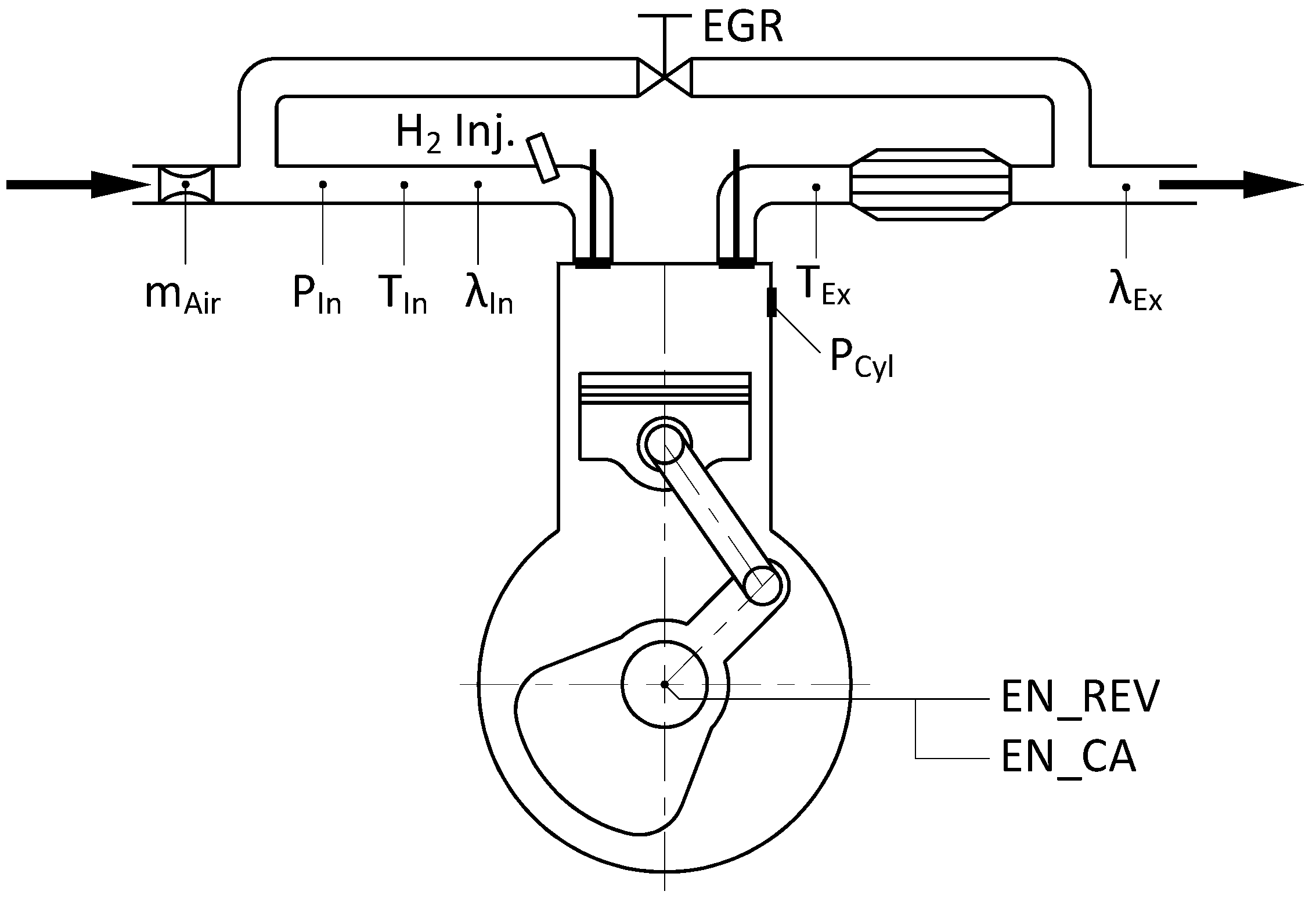
3. Experimental Setup
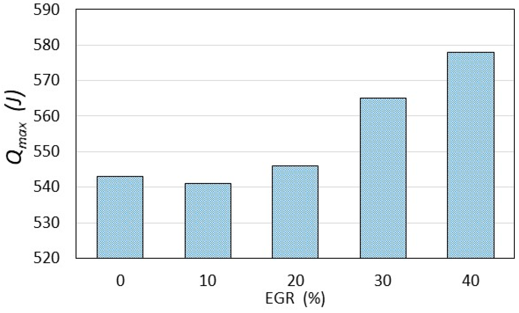
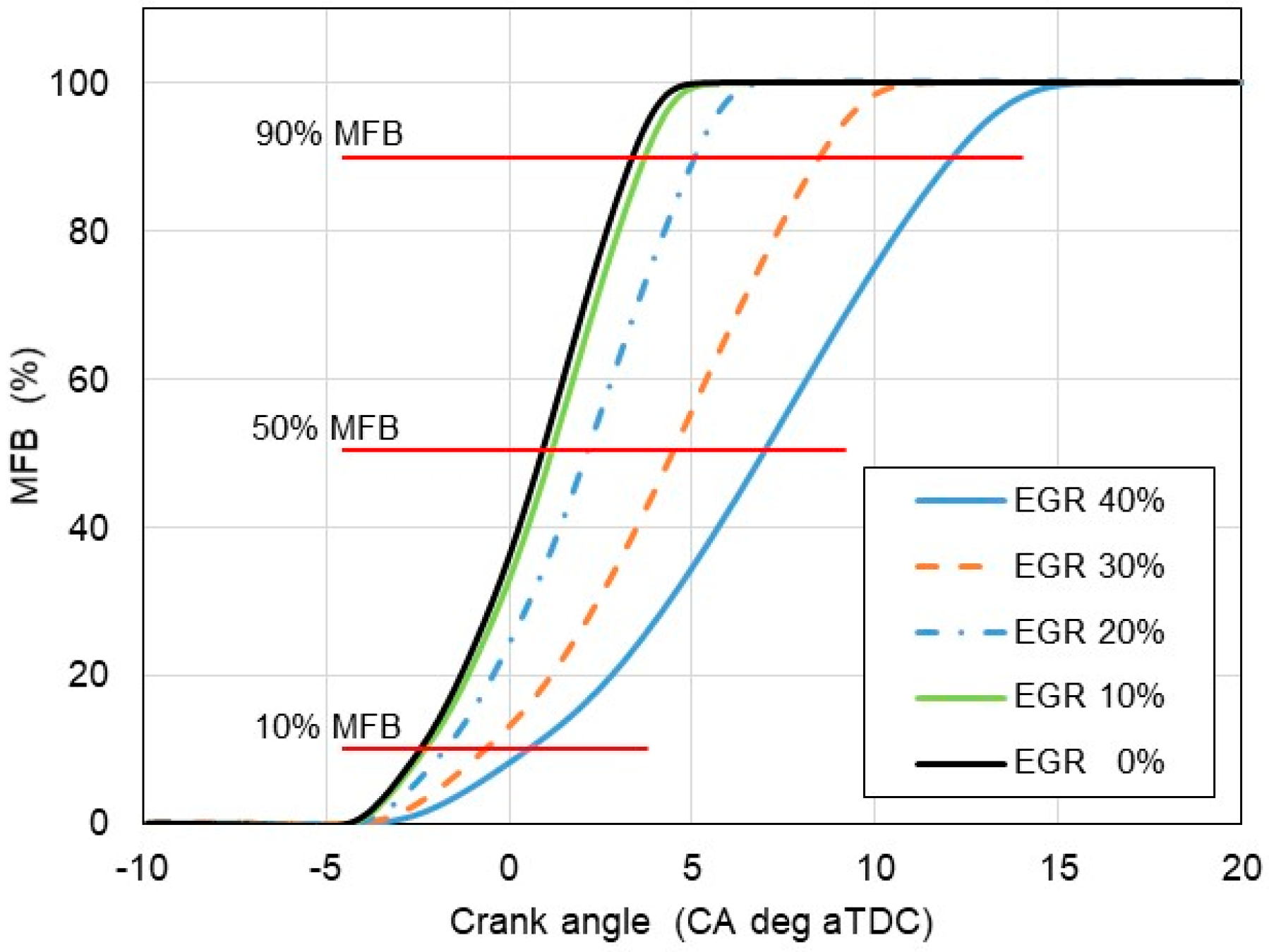
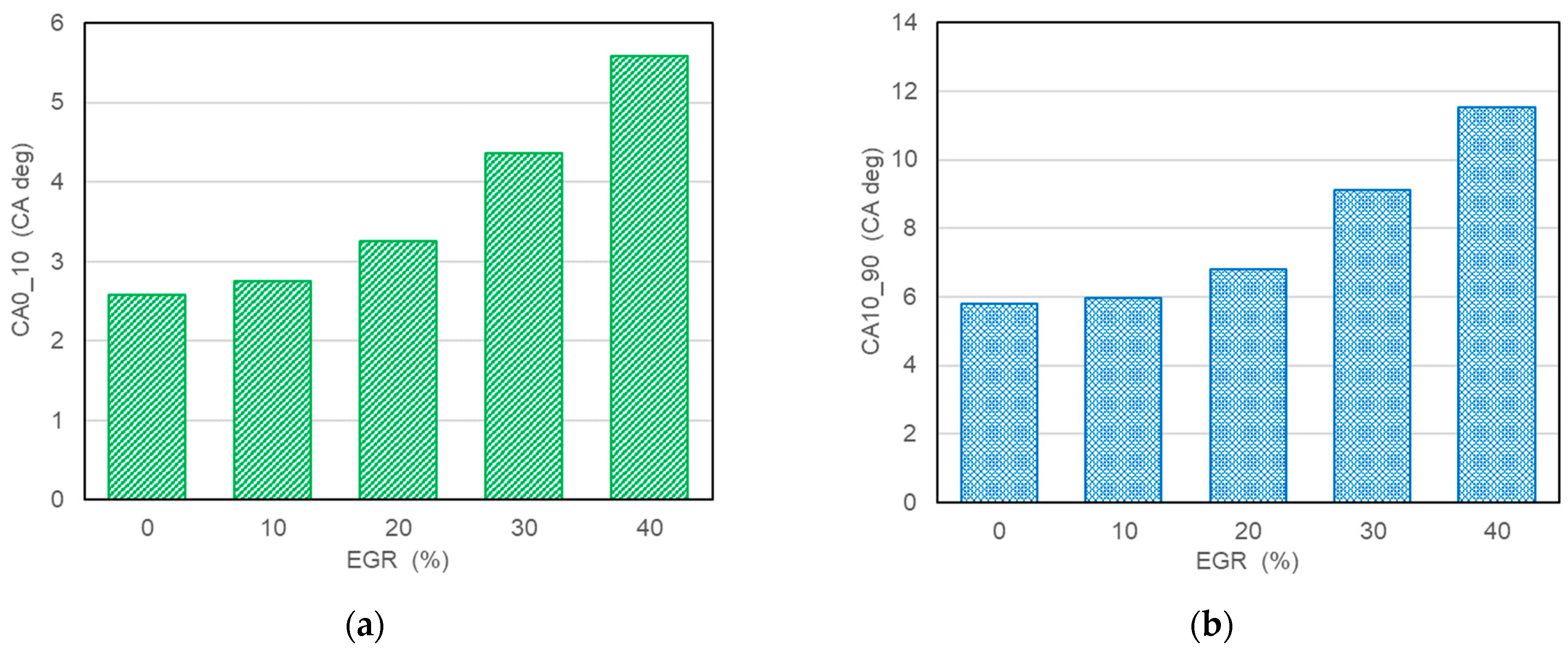
4. Results and Discussion
5. Error Analysis
- the accuracy of the analytical method for calculating the released heat,
- the accuracy of the measuring equipment.
5.1. Error in Calculating Released Heat
- T = 1/2∙(Tfinal + Tinit)—mean temperature during the combustion process;
- n = 1/2∙(nfinal + ninit)—mean number of moles during combustion;
- Δn = nfinal − ninit—change in the number of moles during combustion;
- ΔT = Tfinal − Tinit—change in temperature during combustion.
- The results of the conducted experiments, which took into account the most unfavorable conditions for temperature and mole number from the test with EGR% = 0 one can obtain as follows: Tfinal = 2353 K (2080 °C), Tinit = 733 K (460 °C), nfinal = 6.76, ninit = 5.76 and finally can obtain the result for the x1/x2 ratio (36).
5.2. Error in Combustion Temperature Calculation
5.3. Uncertainties in Measuring Apparatus
6. Conclusions
- Taking into account the change in the number of moles during combustion (molar contraction) is the correct approach that eliminates the simplification of assuming a constant number of moles for the equation of state and the equation for internal energy;
- The error of the classical approach resulting from the assumption of a constant number of moles was calculated. This relative error of the method with the classic approach was approximately 15% both for the calculation of internal energy and for the equation of state in the case of combustion of a hydrogen–air mixture under a stoichiometric ratio;
- Furthermore, the avoidance of molar contraction during hydrogen combustion results in a relative error of up to 17% when calculating the mean combustion temperature inside the cylinder;
- The calculation of the resultant specific heat ratio cp/cv based on separate calculations of cp and cv for the combustible mixture and for exhaust gases depending on the temperature gives better computational accuracy from the HRR method because it eliminates the simplification of assuming a constant cp/cv ratio;
- Using a new approach to the analysis of both heat release and temperature with a single-zone, 0D computational model for a hydrogen-powered engine confirms its usefulness;
- The results of experimental tests confirm a slowdown in the combustion process with an increase in the exhaust gas recirculation ratio in a hydrogen-powered engine. This implies lower combustion temperature, indicated mean effective pressure and, finally lower NOx formation according to the thermal NOx mechanism proposed by Zeldovich;
- The highest EGR was 40% at which the engine operated stably.
Author Contributions
Funding
Data Availability Statement
Acknowledgments
Conflicts of Interest
Abbreviations
| aTDC | after top dead center |
| CA | crank angle |
| CA0_10 | initial combustion phase |
| CA10_90 | final combustion phase |
| EGR | exhaust gases recirculation |
| HRR | heat-release rate |
| IC | internal combustion |
| MFB | mass fraction of fuel burnt |
| MW | molecular weight |
| NOx | nitric oxides |
| Q | heat |
| T | temperature |
| W | engine useful work |
| U | internal energy |
| cp | specific heat at constant pressure |
| cv | specific heat at constant volume |
| k | coefficient for EGR share |
| m | mass |
| n | number of moles |
| p | in-cylinder pressure |
| Subscripts | |
| init | begin of combustion |
| final | end of combustion |
| b | burnt |
| u | unburnt |
References
- Heywood, J.B. Internal Combustion Engine Fundamentals, 2nd ed.; McGraw-Hill College: New York, NY, USA, 2018; ISBN 9781260116106. [Google Scholar]
- Zeleznik, F.J.; McBride, B.J. Modeling the Internal Combustion Engine. NASA Ref. Publ. 1985, 1094, 19850011423. [Google Scholar]
- Goldsborough, S.S. On the Rate of Heat Release for High-Boost, Low-Temperature Combustion Schemes: Accounting for Compressibility Effects. Combust. Sci. Technol. 2009, 181, 729–755. [Google Scholar] [CrossRef]
- Nande, A.M.; Szwaja, S.; Naber, J. Impact of EGR on Combustion Processes in a Hydrogen Fuelled SI Engine; SAE Technical Paper 2008-01-1039; SAE International: Warrendale, PA, USA, 2008. [Google Scholar]
- Ihsan Shahid, M.; Rao, A.; Farhan, M.; Liu, Y.; Ma, F. Comparative Analysis of Different Heat Transfer Models, Energy and Exergy Analysis for Hydrogen-Enriched Internal Combustion Engine under Different Operation Conditions. Appl. Therm. Eng. 2024, 247, 123004. [Google Scholar] [CrossRef]
- Woschni, G. A Universally Applicable Equation for the Instantaneous Heat Transfer Coefficient in the Internal Combustion Engine; SAE Technical Paper 670931; SAE International: Warrendale, PA, USA, 1967. [Google Scholar]
- Annand, W.J.D. Heat Transfer in the Cylinders of Reciprocating Internal Combustion Engines. Proc. Inst. Mech. Eng. 1963, 177, 973–996. [Google Scholar] [CrossRef]
- Hohenberg, G.F. Advanced Approaches for Heat Transfer Calculations; SAE International: Warrendale, PA, USA, 1979. [Google Scholar]
- Lanzafame, R.; Messina, M. Ice Gross Heat Release Strongly Influenced by Specific Heat Ratio Values. Int. J. Automot. Technol. 2003, 4, 125–133. [Google Scholar]
- Tunestål, P. Self-Tuning Gross Heat Release Computation for Internal Combustion Engines. Control Eng. Pract. 2009, 17, 518–524. [Google Scholar] [CrossRef]
- Garcia, M.T.; Jiménez-Espadafor Aguilar, F.J.; Becerra Villanueva, J.A.; Trujillo, E.C. Analysis of a New Analytical Law of Heat Release Rate (HRR) for Homogenous Charge Compression Ignition (HCCI) Combustion Mode versus Analytical Parameters. Appl. Therm. Eng. 2011, 31, 458–466. [Google Scholar] [CrossRef]
- Mauro, S.; Şener, R.; Gül, M.Z.; Lanzafame, R.; Messina, M.; Brusca, S. Internal Combustion Engine Heat Release Calculation Using Single-Zone and CFD 3D Numerical Models. Int. J. Energy Environ. Eng. 2018, 9, 215–226. [Google Scholar] [CrossRef]
- Gatowski, J.A.; Balles, E.N.; Chun, K.M.; Nelson, F.E.; Ekchian, J.A.; Heywood, J.B. Heat Release Analysis of Engine Pressure Data; SAE International: Warrendale, PA, USA, 1984. [Google Scholar]
- Brunt, M.F.J.; Rai, H.; Emtage, A.L. The Calculation of Heat Release Energy from Engine Cylinder Pressure Data; SAE International: Warrendale, PA, USA, 1998. [Google Scholar]
- Egnell, R. Combustion Diagnostics by Means of Multizone Heat Release Analysis and No Calculation; SAE International: Warrendale, PA, USA, 1998. [Google Scholar]
- Olanrewaju, F.O.; Wu, Y.; Li, H.; Andrews, G.; Phylaktou, H. An Improved Heat Release Rate (HRR) Model for the Analysis of Combustion Behaviour of Diesel, GTL, and HVO Diesel; SAE Technical Paper No. 2020-01-2060; SAE International: Warrendale, PA, USA, 2020. [Google Scholar]
- Ebrahimi, R. Effect of Specific Heat Ratio on Heat Release Analysis in a Spark Ignition Engine. Sci. Iran. 2011, 18, 1231–1236. [Google Scholar] [CrossRef][Green Version]
- Ceviz, M.A.; Kaymaz, İ. Temperature and Air–Fuel Ratio Dependent Specific Heat Ratio Functions for Lean Burned and Unburned Mixture. Energy Convers. Manag. 2005, 46, 2387–2404. [Google Scholar] [CrossRef]
- Rassweiler, G.M.; Withrow, L. Motion Pictures of Engine Flames Correlated with Pressure Cards; SAE International: Warrendale, PA, USA, 1938. [Google Scholar]
- Brunt, M.F.J.; Emtage, A.L. Evaluation of Burn Rate Routines and Analysis Errors; SAE Technical Paper No. 970037; SAE International: Warrendale, PA, USA, 1997. [Google Scholar]
- Durkin, K.; Khanafer, A.; Liseau, P.; Stjernström-Eriksson, A.; Svahn, A.; Tobiasson, L.; Andrade, T.S.; Ehnberg, J. Hydrogen-Powered Vehicles: Comparing the Powertrain Efficiency and Sustainability of Fuel Cell versus Internal Combustion Engine Cars. Energies 2024, 17, 1085. [Google Scholar] [CrossRef]
- Shadidi, B.; Najafi, G.; Yusaf, T. A Review of Hydrogen as a Fuel in Internal Combustion Engines. Energies 2021, 14, 6209. [Google Scholar] [CrossRef]
- Szwaja, S.; Naber, J.D. Dual Nature of Hydrogen Combustion Knock. Int. J. Hydrogen Energy 2013, 38, 12489–12496. [Google Scholar] [CrossRef]
- Szwaja, S. Dilution of Fresh Charge for Reducing Combustion Knock in the Internal Combustion Engine Fueled with Hydrogen Rich Gases. Int. J. Hydrogen Energy 2019, 44, 19017–19025. [Google Scholar] [CrossRef]
- Verhelst, S.; Vancoillie, J.; Naganuma, K.; De Paepe, M.; Dierickx, J.; Huyghebaert, Y.; Wallner, T. Setting a Best Practice for Determining the EGR Rate in Hydrogen Internal Combustion Engines. Int. J. Hydrogen Energy 2013, 38, 2490–2503. [Google Scholar] [CrossRef]
- Misul, D.A.; Scopelliti, A.; Baratta, M. High-Performance Hydrogen-Fueled Internal Combustion Engines: Feasibility Study and Optimization via 1D-CFD Modeling. Energies 2024, 17, 1593. [Google Scholar] [CrossRef]
- Lebedevas, S.; Raslavičius, L.; Drazdauskas, M. Comprehensive Correlation for the Prediction of the Heat Release Characteristics of Diesel/CNG Mixtures in a Single-Zone Combustion Model. Sustainability 2023, 15, 3722. [Google Scholar] [CrossRef]
- Lebedevas, S.; Žaglinskis, J.; Drazdauskas, M. Development and Validation of Heat Release Characteristics Identification Method of Diesel Engine under Operating Conditions. J. Mar. Sci. Eng. 2023, 11, 182. [Google Scholar] [CrossRef]
- Tang, Y.; Li, H.; Jiang, Y.; Liang, W.; Zhang, J. The Control-Oriented Heat Release Rate Model for a Marine Dual-Fuel Engine under All the Operating Modes and Loads. J. Mar. Sci. Eng. 2023, 11, 64. [Google Scholar] [CrossRef]
- Szwaja, S.; Naber, J.D. Exhaust Gas Recirculation Strategy in the Hydrogen SI Engine. J. Kones-Powertrain Transp. 2007, 14, 457–464. [Google Scholar]
- Szwaja, S.; Ansari, E.; Rao, S.; Szwaja, M.; Grab-Rogalinski, K.; Naber, J.D.; Pyrc, M. Influence of Exhaust Residuals on Combustion Phases, Exhaust Toxic Emission and Fuel Consumption from a Natural Gas Fueled Spark-Ignition Engine. Energy Convers. Manag. 2018, 165, 440–446. [Google Scholar] [CrossRef]


| γu | a0 | a1 | a2 | a3 |
| 1.4485 | −0.0001 | 4 × 10⁻⁸ | −4 × 10⁻¹² | |
| γb | a0 | a1 | a2 | a3 |
| 1.4482 | −0.0002 | 7 × 10⁻⁸ | −9 × 10⁻¹² |
| Parameter | Unit | Data |
|---|---|---|
| Compression Ratio | - | 8 |
| Cylinder Bore | mm | 82.6 |
| Stroke | mm | 114.3 |
| Connecting Rod Length | mm | 254 |
| Displacement | cm3 | 611 |
| Intake Valve Open | CA deg aTDC | 10° |
| Intake Valve Closure | CA deg aBDC | 34° |
| Exhaust Valve Open | CA deg bBDC | 40° |
| Exhaust Valve Closure | CA deg aTDC | 15° |
| Engine Speed | rpm | 900 |
| No. | Spark Timing (CA Deg aTDC) | λ (−) | EGR% (%) |
|---|---|---|---|
| 1 | −5 | 1.00–1.03 | 0 |
| 2 | −5 | 1.01–1.03 | 10 |
| 3 | −5 | 1.00–1.02 | 20 |
| 4 | −5 | 1.01–1.04 | 30 |
| 5 | −5 | 1.01–1.03 | 40 |
| Instrument | Range | Accuracy |
|---|---|---|
| Air laminar flowmeter | 0.05…10 m3/h | 0.1% |
| Charge amplifier Kistler | 2…10 pC 10…100 pC 100…2,200,000 pC | <±2% <±0.6% <±0.3% |
| Pressure sensor: Kistler 6061 | 0…200 bar | <±1% |
| Data acq. system: NI BN-2111 | ±10 V | ±0.07% 16 bits ± 1 LSB |
| Thermocouple NiCR-NiAl (K) | (−40)…1140 °C | 1.5 °C |
| Spark timing | −20 ÷ 0 CA deg aTDC | uncertainty: ±0.1 CA deg |
| Combustion phases: CA0-10, CA10-90 | uncertainty: ±0.3 CA deg | |
| Encoder | max. 6000 rpm | 0.3 deg/rev |
Disclaimer/Publisher’s Note: The statements, opinions and data contained in all publications are solely those of the individual author(s) and contributor(s) and not of MDPI and/or the editor(s). MDPI and/or the editor(s) disclaim responsibility for any injury to people or property resulting from any ideas, methods, instructions or products referred to in the content. |
© 2024 by the authors. Licensee MDPI, Basel, Switzerland. This article is an open access article distributed under the terms and conditions of the Creative Commons Attribution (CC BY) license (https://creativecommons.org/licenses/by/4.0/).
Share and Cite
Szwaja, S.; Piotrowski, A.; Szwaja, M.; Musial, D. Thermodynamic Analysis of the Combustion Process in Hydrogen-Fueled Engines with EGR. Energies 2024, 17, 2833. https://doi.org/10.3390/en17122833
Szwaja S, Piotrowski A, Szwaja M, Musial D. Thermodynamic Analysis of the Combustion Process in Hydrogen-Fueled Engines with EGR. Energies. 2024; 17(12):2833. https://doi.org/10.3390/en17122833
Chicago/Turabian StyleSzwaja, Stanislaw, Andrzej Piotrowski, Magdalena Szwaja, and Dorota Musial. 2024. "Thermodynamic Analysis of the Combustion Process in Hydrogen-Fueled Engines with EGR" Energies 17, no. 12: 2833. https://doi.org/10.3390/en17122833
APA StyleSzwaja, S., Piotrowski, A., Szwaja, M., & Musial, D. (2024). Thermodynamic Analysis of the Combustion Process in Hydrogen-Fueled Engines with EGR. Energies, 17(12), 2833. https://doi.org/10.3390/en17122833


