Abstract
A major issue with spark-ignition engines is their fuel inefficiency and negative environmental effects, especially in urban driving situations. This topic is of utmost importance considering the increasing apprehension over environmental contamination and the need for enhanced energy efficiency. The research’s originality resides in its strategy to tackling this issue without necessitating intricate engine changes, a manner not commonly used. The research uses a dual strategy that integrates both theoretical and experimental approaches. The theoretical component entails developing models to forecast the effects of different cylinder deactivation strategies on fuel consumption and emissions. Important factors to address in this theoretical model are the introduction of air into cylinders that are not in use and the stopping of fuel supply. The experimental component involves conducting bench experiments on a modified spark-ignition engine to verify the theoretical conclusions. These tests assess performance metrics, such as fuel economy and environmental effect, under different load situations. The study’s findings are encouraging. The study reveals that disabling a specific group of cylinders while permitting unrestricted air intake might result in significant improvements in fuel economy, anywhere from 1.5% to 10.5%, depending on the engine’s workload. Bench testing revealed a maximum improvement of 10.8%, which demonstrates the efficacy of this strategy. The study’s findings indicate that the use of the integrated power regulation approach greatly improves fuel efficiency and decreases the impact of the environmental consequences of spark-ignition engines, especially in situations of low load and idling. This technology demonstrates its feasibility as a solution that can be seamlessly incorporated into current engine designs with few adjustments, providing a practical and environmentally responsible option for enhancing vehicle performance. The results indicate that this approach has wide-ranging potential uses in the automotive sector, particularly for urban cars that often function in situations with modest levels of demand. By using this approach, manufacturers may attain enhanced fuel efficiency and diminish emissions, this contributing to the development of more sustainable urban transportation options.
1. Introduction
The fuel economy and environmental performance of internal combustion engines (ICEs) largely depend on the operating modes determined by cars’ driving conditions [1]. The fuel efficiency and ecological impact of ICEs are primarily influenced by the operating modes dictated by the driving circumstances of vehicles [2]. This interdependence is crucial since ICEs often demonstrate suboptimal fuel economy and increased emissions while operating under low-load and idle circumstances [3]. Inefficiencies arise from elevated pumping losses and poor combustion processes under such circumstances, resulting in elevated emissions of pollutants such as carbon dioxide (CO2), nitrogen oxides (NOx), and hydrocarbonates (HC) [4]. Hence, enhancing the fuel economy in various operating modes may greatly diminish the environmental consequences of ICEs, thus highlighting the crucial need for research and innovation in this domain [5]. Recent research has emphasized the significance of using novel techniques like cylinder deactivation and optimized fuel–air mixes to improve the performance of ICEs [6]. Implementing these tactics may result in significant improvements in fuel efficiency, especially under situations of partial load and idling. The results highlight the significant impact of operating modes on the fuel efficiency and environmental impact of ICEs, emphasizing the need for creative solutions to successfully tackle these difficulties [7].
Cylinder deactivation and variable valve timing are important techniques used to enhance fuel economy in ICEs. Different approaches are used to improve the effectiveness of four-stroke spark-ignition engines under partial load conditions. This paper emphasizes that cylinder deactivation may decrease pumping losses and enhance thermal efficiency by disabling some cylinders under low-load situations, therefore minimizing fuel consumption [8]. Utilizing alternative fuels is a notable method to enhance the fuel economy of Spark-Ignition Engines (SIEs). The efficiency and pollutant output of SIEs when fueled with a mixture of hydrogen and natural gas increases and decreases, respectively. Research shows how the introduction of hydrogen might augment the efficiency of combustion and diminish CO2 emissions, thus leading to improved fuel efficiency and a reduced environmental footprint [9]. In a similar vein, [10] investigated the impact of using biofuels in SIEs, observing enhancements in fuel economy and decreases in greenhouse gas emissions when compared to traditional petrol. Emission control systems are essential for improving the fuel economy of SIEs. Jin et al. [11] investigated how sophisticated emission control technologies, such as three-way catalytic converters and exhaust gas recirculation (EGR), affect the fuel economy and emissions of SIEs. Studies have shown that integrating these technologies is effective in maintaining ideal combustion conditions, resulting in enhanced fuel efficiency and decreased emissions of hazardous substances.
Cylinder deactivation is a crucial element of the integrated power control approach. The engine effectively decreases fuel consumption and pollution by selectively deactivating cylinders while operating under low-load situations. Liu et al. [12] investigated the efficacy of this method and found that cylinder deactivation leads to a significant enhancement in thermal efficiency. This improvement is achieved by mitigating pumping losses and enhancing combustion stability, particularly under partial load conditions. This technique enables the engine to function with a reduced number of active cylinders when maximum power is unnecessary, hence improving the total fuel efficiency. Advanced strategies for controlling throttle are equally important. Yang et al. [13] conducted a study to examine the impact of precise throttle control combined with cylinder deactivation. They discovered that optimized throttling may improve fuel economy by reducing the losses often associated with conventional throttling techniques. The meticulous control of the throttle guarantees seamless transitions between various engine loads, enhancing both driving pleasure and fuel economy. Variable valve timing (VVT) and variable valve lift (VVL) technologies are crucial for facilitating the implementation of the combined power regulation approach. These technologies modify the timing and height of the valves to optimize the intake and exhaust of air in the engine, which is essential for ensuring efficient combustion under different load circumstances. Lei et al. [14] found that combining VVT and VVL with cylinder deactivation improves the engine’s adaptability to different driving conditions and increases fuel efficiency. This integration enhances the engine’s flexibility and responsiveness. The study also suggests that using alternative fuels and advanced combustion strategies can further enhance the effectiveness of this combined power regulation method. Liu et al. and Yang et al. observed that combining these methods with cylinder deactivation and sophisticated throttle control may result in substantial enhancements in fuel efficiency and reductions in emissions. For example, the utilization of biofuels or fuels enhanced with hydrogen may improve the efficiency of combustion, hence further decreasing the impact of the environmental consequences of SIEs.
Efficient emission management is a crucial component of the integrated power regulation approach. Advanced emission control technologies, such as three-way catalytic converters and EGR, are necessary to provide ideal combustion conditions and minimize the release of hazardous pollutants. Lei et al. [14] highlighted that the integration of these technologies with cylinder deactivation and VVT/VVL may effectively diminish the emissions of NOx, carbon monoxide (CO), and hydrocarbons, hence enhancing the engine’s environmental friendliness without compromising its fuel efficiency.
Under intense traffic conditions in populated areas, the main modes of operation of internal combustion engines, in particular, SIEs [15], which are the main source of energy for passenger cars, are partial load and high-speed modes [16].
This method of regulation determines the peculiarities of the work process in the modes of partial loads and idling and its influence on the flow of the indicator engine efficiency coefficient (EEC) [17], whose value characterizes the fuel efficiency of the work cycle. Many factors affect the flow of indicator efficiency. One of the most important is the composition of the air–fuel mixture [18,19].
For this study, we chose two methods to disconnect a group of cylinders:
- The use of an unchanged gas distribution system;
- When air with a different temperature is freely admitted to the disconnected group of cylinders. This method included air intake at a temperature of 20–300 °C and a temperature of 130–1500 °C.
The main goal of this study was to improve the fuel economy and decrease environmental impact of spark-ignition engines while operating at low load and in idle circumstances. This is accomplished by using the most appropriate technique for disabling a set of cylinders, which is paired with a comprehensive approach to regulating engine output.
This paper makes the following scientific contributions:
Our research aims to fill the current knowledge gap in the enhancement of fuel efficiency and the reduction in hazardous emissions in spark-ignition engines under low load and in idle circumstances. The study is driven by the need to develop automobile engines that are both more efficient and ecologically sustainable, especially in metropolitan environments where cars often operate in such situations.
A unique approach was devised to perform computational assessments on the effects of cylinder group deactivation on fuel economy and exhaust emissions. This methodology incorporates a unified approach to controlling engine power, which offers a complete framework for assessing various tactics for deactivating spark-ignition engines.
This work establishes a novel correlation for determining the recommended thermal efficiency of the active cylinders. The dependence mentioned is of utmost importance since it stays uniform across different techniques of cylinder group deactivation and is dictated by the intake vacuum settings. This enables a uniform evaluation of thermal efficiency, irrespective of the deactivation technique used.
Another notable addition is the suggested correlation for calculating the mechanical efficiency of the engine while a set of cylinders is disabled. This dependence employs empirically acquired data on mechanical loss pressure and the intake vacuum of the deactivated cylinders. This technique guarantees that the estimates of mechanical efficiency are based on empirical data, hence improving the accuracy and dependability of the findings.
A thorough analysis was carried out to assess the fuel economy and environmental impact of several techniques of deactivating cylinder groups. This analysis was undertaken as part of a combined power regulation approach. The results provide useful insights into the efficacy of various deactivation approaches, aiding in the optimization of spark-ignition engine performance under certain operating conditions.
The study greatly enhances the comprehension of cylinder deactivation and power regulation in spark-ignition engines by addressing these factors. It provides practical methods for enhancing fuel economy and decreasing emissions in real-world scenarios.
2. Methodology of Improvement of the Power Supply System with the Combined Method of Power Regulation
An experimental power supply system, the scheme of which is given in the article [20,21], was used as a basis (see Figure 1).
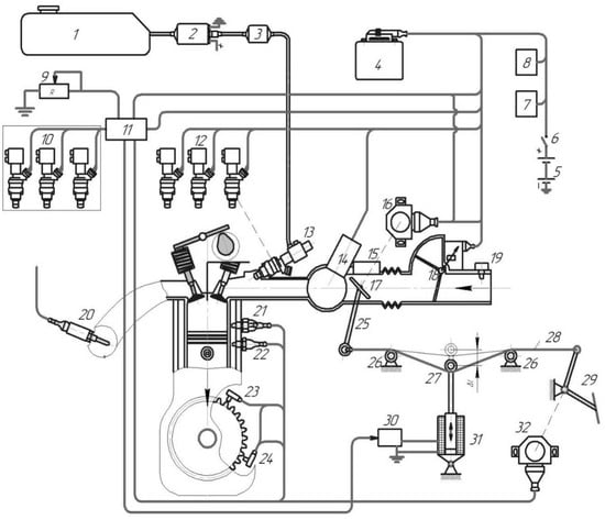
Figure 1.
The scheme of the experimental power system: 1—fuel tank, 2—electric fuel pump, 3—fuel filter, 4—electronic control device (microprocessor), 5—battery, 6—ignition switch, 7—main relay, 8—pump relay, 9—ballast resistance, 10—disconnected injectors, 11—electronic unit for controlling the nozzles, 12—non-inverting nozzles, 13—fuel distributor, 14—cold start system, 15—idling speed stabilization device, 16—sensor of position and a value of accelerating throttle valve, 17—throttle valve, 18—air vent, 19—air temperature sensor, 20—λ-sensor, 21—thermal timer, 22—engine temperature sensor, 23—crankshaft angle sensor, 24—speed sensor, 25—throttle control lever, 26—locking roller, 27—tension roller, 28—throttle valve drive cable, 29—gas pedal, 30—relay for electromagnet switching, 31—electromagnet, and 32—load sensor.
Two methods of disconnecting a group of cylinders were chosen for the study:
- The use of an unchanged gas distribution system;
- When air with a different temperature is freely admitted to the disconnected group of cylinders.
To study these methods of disconnecting a group of cylinders and, accordingly, to determine the effectiveness of the combined method of power regulation, a number of structural changes were made to the gas distribution system (see Figure 2). To disconnect the group of working cylinders A (1-2-3) from group B (4-5-6), which are turned off, valve 4 was used, which is used in a number of Opel engine models. For free air intake into the disconnected group of cylinders B, valve 7 was installed.
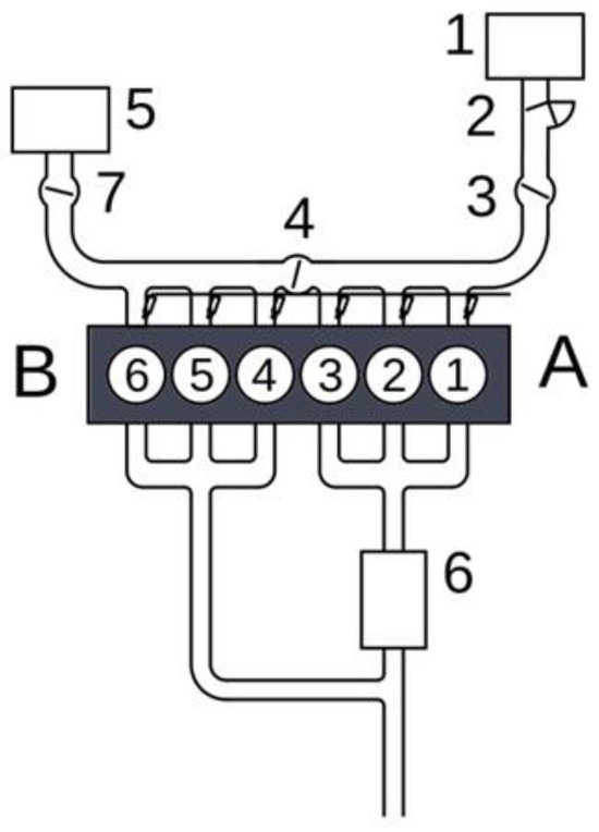
Figure 2.
Diagram of the gas distribution system with changes made to implement methods of disconnecting a group of cylinders. 1—air filter of the standard intake system; 2—air flow meter; 3—throttle valve; 4—valve for disconnecting groups of cylinders; 5—air filter for free air intake into the disconnected group of cylinders; 6—catalytic converter; 7—damper for free air intake into the disconnected group of cylinders.
Such changes in the gas distribution system made it possible to conduct research on the engine operating on six cylinders when valve 4 is open and valve 7 is closed and to investigate the following methods of disconnecting a group of cylinders:
- A—disconnection of fuel supply (valve 4 is open and valve 7 is closed) (see Figure 3);
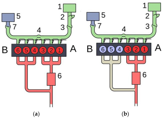 Figure 3. The position of the flaps with an unchanged intake system: (a) work on all cylinders and (b) when the fuel supply is turned off.
 - B—free air intake with and without heating (valve 4 closed and valve 7 open) (see Figure 4).
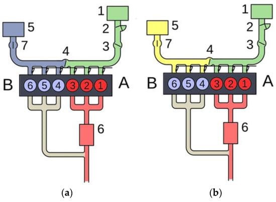 Figure 4. The position of the flaps during free air intake into the disconnected cylinder group: (a) without heating and (b) with heating.
The six-cylinder in-line engine by the Opel company, with a working volume of 3 L, model C30LE (hereinafter—6Ch 9.5/6.98), was chosen as the object of experimental research. The engine is equipped with an electronic fuel injection control system, M4.1 Motronic, with feedback and a neutralization system for the exhaust. The engine is installed on the SGEU-100 motor brake stand and connected to the stand using a standard gearbox.
In order to check different methods of disconnecting a group of cylinders in the engine intake system, changes were made that allowed for checking of the following implementation methods:
- Cutting off the fuel supply with an unchanged gas distribution system
- Disconnection of the fuel supply with the supply of fresh air to the disconnected group of cylinders (with and without heating).
To assess the fuel efficiency of an SIE when using the combined method of power regulation with different techniques for cylinder disconnection, it is necessary to determine the fuel efficiency of the engine in the entire range of loads where the engine operates with cylinders disconnected in one way or another [22]. At higher loads, the engine works on all cylinders, and the dependence of fuel consumption on the load remains unchanged [23].
It is possible to compare the fuel efficiency of the engine during operation with disconnected cylinders based on the load from idle to the maximum energy indicators [24].
It is known that the assessment of the fuel efficiency of an internal combustion engine is based on the brake-specific fuel consumption (BSFC) [25], which is determined by (1)
where Hu is the lower heat of combustion of fuel (kJ/kg), ηi is the indicator EEC when the cylinders are disconnected—they are classified as working cylinders—and ηm is the mechanical EEC engine.
It is appropriate to consider the change of the named EEC separately since these EECs can change differently in a wide range of loads.
Disabling the cylinders using the methods under consideration does not affect the work process in the working cylinders and the indicator EEC [26].
When determining the dependence of indicators and mechanical EEC on the load, it is more convenient to estimate the load by the degree of throttling of the working cylinders since the indicators characterizing the work process are given depending on the throttling [27].
Let us consider the factors that affect the dependence of the indicator EEC on the degree of throttling. The degree of throttling is estimated by the vacuum at the inlet to the engine (Δpk) or the pressure in the cylinder at the end of the inlet (pa).
The indicator EEC depends on many factors when reducing the external load and adjusting the fuel–air mixture, as discussed above [28].
A number of dependencies for determining the indicator EEC are known. One of them is dependency (2):
where l0 is the theoretically necessary amount of air for the combustion of 1 kg of fuel, kg/kg, Hu is the lower heat of combustion (MJ/kg), λ is the coefficient of excess air, pi average is the indicator pressure (MPa), ηv is the volumetric efficiency, and ρk is the air density, kg/m3.
The computations (2) were performed using the following conditions: l0 = 14.8 kg/kg, Hu = 43.5 MJ/kg, and ρk = 1.22 kg/m3.
One of the important indicators in this dependence is the volumetric efficiency ηv. This coefficient, taking into account the unevenness of heat capacities, cylinder recharging, and combustion chamber purging, can be calculated according to the dependence [29]:
where ε is the degree of compression, λ1 is the recharge coefficient, pa is the pressure in the cylinder at the end of the inlet (kPa), p0 is the pressure at the engine inlet (kPa), ψ is the coefficient that takes into account the difference in the heat capacity of the fresh mixture and the mixture at the end of the inlet, λg is the coefficient of cleaning the combustion chamber of residual gases, T0 is the engine inlet temperature (K), ΔT is heating of the fresh charge in the intake process (K), and pr is the pressure at the end of discharge (kPa).
According to source [30,31], coefficients included in dependence (3) include λ1 = 1.02…1.03, ψ = 1.17 (for λ = 1.0), and λg = 0.97.
Pressure in the cylinder at the end of the intake stroke (4):
where Δpa is the pressure loss in the intake system.
Pressure losses in the intake system are calculated using Equation (5):
where β is the decay rate of the fresh charge in the considered section, ξ_IN is the coefficient of hydraulic resistance of the intake system referred to as its highest section, w is the average speed of gas movement in the passage section of the valve (m/s), and ρ0 is the charge density at the engine inlet (kg/m3).
The w value was chosen by w = 50…130. For modern automobile engines . Calculations were carried out [32,33], the ultimate goal of which is the dependence of the indicator EEC on the degree of throttling, which was estimated using the rarefaction at the inlet Δpk. Since the filling coefficients were calculated according to dependence (3), the load was estimated by the pressure in the engine cylinder at the end of the intake pa, and the losses in the intake system Δpa were calculated according to dependence (5). At the same time, the following parameters β2 + ξIN = 2.6…3.3 were taken: w = 90 (m/s) and ρ0 = 1.22 (kg/m3). The mechanical efficiency of different ways of disconnecting the cylinders was determined by dependence (6) [34].
where the variable pm represents the average pressure of mechanical losses when disconnecting the cylinders using different methods, measured in Mpa, and pi is the average indicator pressure when the cylinders are turned off, measured in MPa. This pressure’s dependence on the vacuum at the inlet is the same for different ways of shutting off the cylinders.
The difference between the ways of disconnecting the cylinders will take place only in the mechanical losses, which are estimated using the average pressure (pm). As a result, the average effective pressure (pe) will be different, depending on whether it is necessary to evaluate the performance of the engine when using different methods of disconnecting a group of cylinders.
Mass emissions of exhaust per unit of time were calculated according to dependencies [35].
where Ci′ and Ci″ are the concentrations of exhaust in % and ppm, respectively, μi is the molecular weight of the ith exhaust (kg/kmol), and Mexhaust is the amount of fuel combustion products (kmol/h).
When calculating the quantity of fuel combustion products, the state of the fuel was taken into account. For CO, HC, and CO2, the concentrations of which were determined using the infrared method, the gases were analyzed dry; for NOx, the concentrations of which were determined in heated combustion products, the gases were analyzed wet [36].
The number of combustion products was calculated according to the dependence (9).
where Bfuel is hourly fuel consumption (kg/h), Bair is hourly air consumption (kg/h), and a and b are calculated coefficients that depend on the state of the exhaust and the composition of the fuel–air mixture.
As can be seen from the load characteristics of the 6Ch9.5/6.98 engine (see Figure 1), the composition of the fuel–air mixture, except for full load, is close to stoichiometric (λ = 0.985…0.994).
For such a composition
When calculating according to Formulas (7) and (8), the values used in the calibration of the devices were: MCO = 28 kg/kmol, MCO2 = 44 kg/kmol, MHC = 86 kg/kmol, and MNOx = 30 kg/kmol [37].
3. Theoretical Studies
The performed calculations showed that the use of these coefficients leads to significant errors in the calculation of pa and, accordingly, the filling coefficient ηv [38]. Using the data of experimental studies, in particular, the load characteristic on the 6F9.5/6.98 engine [39], at the rotation frequency n = 1800 rpm, for work on six cylinders, the volumetric efficiency was calculated depending on the vacuum at the intake Δpk (see Figure 5). Using the same loading characteristic data, the dependence of the average indicator pressure on the rarefaction at the inlet was calculated (see Figure 6).
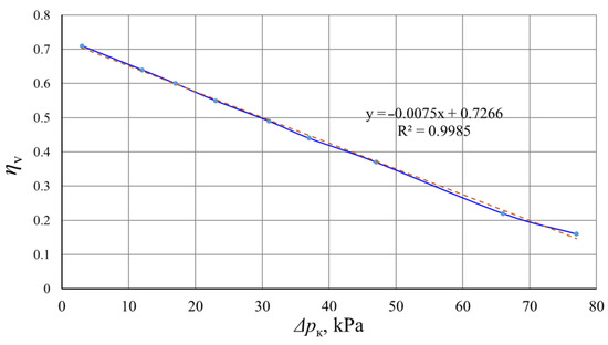
Figure 5.
Dependence of volumetric efficiency on intake rarefaction Δpk (n = 1800 rpm) for the 6F9.5/6.98 engine.
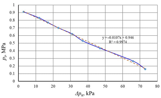
Figure 6.
Average indicator pressure vs. intake vacuum Δpk (n = 1800 rpm) for the 6Ch9.5/6.98 engine.
A comparison of the values calculated using formula (2) and the experimentally obtained values of the indicator EEC was carried out using graphical dependences of ηi on Δpk (see Figure 7). The graphs show that the dependences ηi obtained through calculations and according to the results of the experiment practically coincide. Engine performance calculations for three cylinders using different methods of cylinder shutdown were conducted at a speed of n = 2000 rpm with a ratio of 6F9.5/6.98. With the considered methods of disconnecting the cylinders, the dependence of the indicator efficiency of the working cylinders on the rarefaction at the intake is the same (see Figure 6).
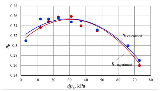
Figure 7.
Calculated vs. experimental dependence of indicator EEC on intake vacuum Δpk (n = 1800 rpm) for the 6F9.5/6.98 engine.
Figure 8 shows the average indicator pressure pi, the pressure of mechanical losses pm, and the average effective pressure pe, depending on the rarefaction at the inlet Δpk with an unchanged gas exchange system. According to Formula (6), the mechanical EEC from Δpk (see Figure 9) is dependent on an unchanged gas exchange system [40].
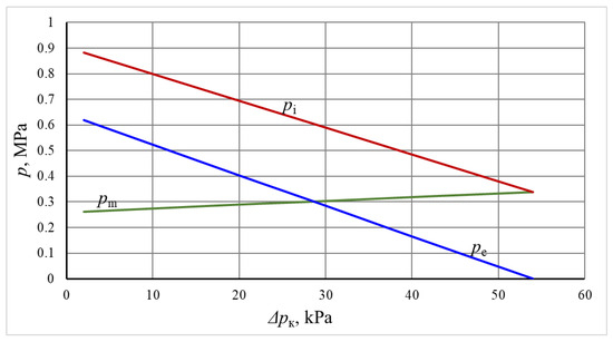
Figure 8.
Dependence of pi, pe, and pm on intake vacuum ∆pk with three cylinders off (n = 2000 rpm) for the 6Ch9.5/6.98 engine.
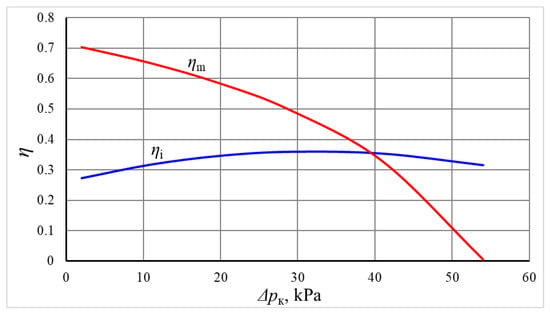
Figure 9.
Dependence of indicator and mechanical EEC on intake rarefaction with three cylinders off (n = 2000 rpm) for the 6Ch9.5/6.98 engine.
Cranking the warmed-up engine with an unchanged gas exchange system and free air intake into the disconnected group of cylinders (with and without air heating) determined the average pressure of mechanical losses. As can be seen from the shown dependencies (see Figure 10), the average pressure of mechanical losses pm differs significantly for different ways of disconnecting cylinders.
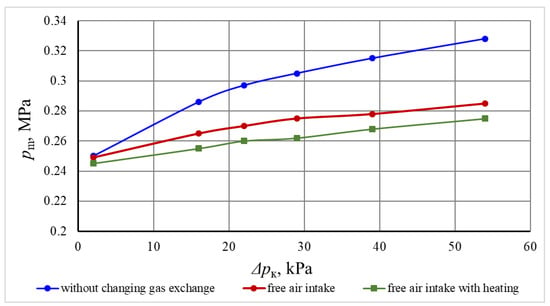
Figure 10.
EEC dependence on intake rarefaction with three cylinders off (n = 2000 rpm) for the 6Ch9.5/6.98 engine.
The value of pm is much smaller with free air intake into disconnected cylinders (without air heating and with heating). The difference between them is insignificant; it is necessary to take into account the complexity of the implementation of the method [41]. A significant reduction in mechanical losses with these methods is due to a reduction in pumping losses. This leads to an increase in the mechanical EEC. The calculated dependences of ηm (∆pk) for different methods are shown in Figure 11.
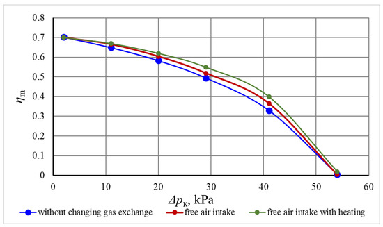
Figure 11.
Dependence of mechanical ηm EEC on intake rarefaction ∆pk for the 6F9.5/6.98 engine (n = 2000 rpm).
This regularity of ηm (∆pk) for different shutdown methods is explained by the fact that for the idling mode, the value of ∆pk practically does not differ for different methods; it is within 2…3 kPa. For the maximum load mode, when the throttle valve in the group of disconnected cylinders is fully open with an unchanged gas exchange system, the mechanical losses for all methods are practically the same. The difference is 1…2 kPa. Therefore, these points on the graphs coincide.
An objective assessment of the fuel efficiency of the engine is the dependence of the BSFC on the effective indicators, in particular, the average effective pressure pe [42]. Therefore, we calculated the dependence pe (∆pk) for the considered methods of disconnecting a group of cylinders. These dependencies are shown in Figure 12.
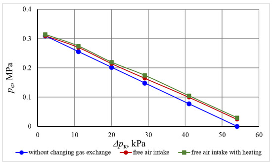
Figure 12.
Dependence of pe on intake vacuum ∆pk with three cylinders off (n = 2000 rpm) for the 6Ch9.5/6.98 engine.
Using the dependences pe (∆pk), ηI (∆pk), and ηm (∆pk) according to Formula (1), the dependence of the BSFC on the average effective pressure was calculated [27]. These dependencies are shown in Figure 13. It can be seen from them that the greatest improvement can be achieved with free intake and heating of air in the disconnected group of cylinders. In comparison with turning off a group of cylinders with an unchanged gas exchange system, the saving is 1.5…13.5%. With free air intake without heating into the disconnected cylinder group, fuel efficiency improves by 1.5…10.5% compared to an unchanged gas exchange system.
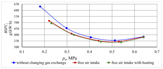
Figure 13.
Dependence of BSFC on pe for the 6Ch9.5/6.98 engine (n = 2000 rpm).
4. Results and Discussion
In order to accurately assess the environmental impact of various cylinder deactivation systems under a unified power regulation strategy, it is crucial to standardize the parameters that influence exhaust emissions while ignoring the load factor [43]. More precisely, this involves ensuring a steady rate of fuel and air consumption every hour, as well as controlling the levels of pollutants in relation to the vacuum pressure in the engine’s intake, which indicates the engine’s workload [7].
The investigated techniques of cylinder group deactivation demonstrate a consistent relationship between environmental indicators, fuel consumption, and air consumption with respect to the intake vacuum. Experimentally, it is conceivable to deactivate the fuel supply to a set of cylinders without modifying the gas distribution system. This makes it a viable reference point for comparison with other approaches.
The load characteristics of a 6Ch9.5/6.98 engine were experimentally evaluated. The engine was working on three cylinders at a speed of 2000 rpm, and no changes were made to the gas distribution system. Please refer to Figure 1 for further details. The independent measure employed was the intake vacuum behind the Δpk. An installation of a three-component catalytic converter was conducted, and the levels of pollutants as well as the composition of the λ were measured using a BOSCH BEA 060 gas analyzer.
The calculated pi for all cylinder shutdown methods will be the same, depending on the vacuum at the intake.
Figure 14 depicts the relationships between several engine performance measurements and Me for the 6Ch9.5/6.98 engine. The λ value stays generally stable as the effective torque rises. The consistency of the air–fuel mixture indicates that combustion is steady at various levels of torque. The pressure indicator exhibits a small reduction as the effective torque increases. As the engine load rises, the pressure from the combustion process decreases, suggesting a possible modest decline in combustion efficiency. As the torque rises, there is a gradual decrease in effective pressure. Like the indication pressure, the effective pressure also declines, indicating a modest loss in the engine’s efficiency in turning fuel into usable work with increasing loads. As the torque increases, the fuel consumption per unit of energy generated per hour falls. Higher loads lead to improved fuel economy, suggesting that the engine performs more efficiently when subjected to bigger loads. The concentration of CO rises as the torque increases. Increased engine loads contribute to greater levels of incomplete combustion, leading to elevated emissions of CO. The concentration of CO2 stays essentially constant regardless of the varying torque levels. The consistent levels of CO2 emissions suggest steady combustion efficiency in terms of the by-products produced throughout full combustion.
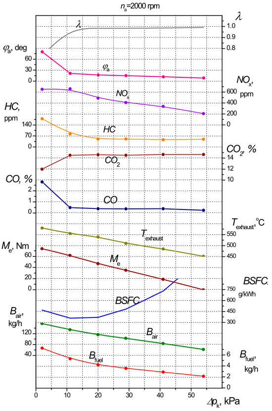
Figure 14.
Performance indicators vs. intake rarefaction Δpk of the 6Ch9.5/6.98 engine operating on three cylinders.
As the torque rises, there is a modest decrease in engine speed. Under increasing loads, the engine speed experiences a small reduction, which is a common occurrence since the increased load demands more power. The mechanical pressure loss exhibits a consistent reduction as the torque increases. Higher torque levels result in less mechanical losses, leading to improved mechanical efficiency. The mechanical efficiency is directly proportional to the effective torque. Increased loads enhance the efficiency of the engine’s mechanical components, resulting in enhanced performance. The air–fuel ratio and CO2 emissions exhibit a consistent pattern, suggesting a steady level of combustion efficiency across various torque levels. As torque rises, fuel consumption per unit of energy generated falls, indicating improved fuel economy at greater loads. Higher torque levels are associated with a discernible rise in CO emissions, indicating a greater occurrence of incomplete combustion under larger loads. Both mechanical losses and mechanical efficiency exhibit positive trends, with losses declining and efficiency improving as torque rises. The observed patterns indicate that running the engine at greater workloads may enhance fuel economy but may lead to increased carbon monoxide emissions. Ensuring a balance between load and efficiency is essential for maximizing economic and environmental performance. Ensuring a steady air–fuel ratio is crucial for maintaining consistent engine performance, as seen by the unchanging nature of the process. The larger loads result in a gain in mechanical efficiency, which is advantageous as it demonstrates that the engine’s design is capable of properly handling greater operating demands. These trends provide useful information for enhancing engine performance and minimizing environmental impact, especially in terms of fuel economy and emission control.
The pi for all cylinder deactivation mechanisms is determined by the intake vacuum. By using the loading characteristic data, we were able to determine the mass emissions’ reliance on the intake vacuum. Additionally, we generated the Bi(pe) dependencies based on the pe(Δpk) relationships, as shown in Figure 12. Figure 15 demonstrates the relationship between hourly carbon monoxide emissions (BCO) and pe. HC, NOx, and CO2 were assessed for similar interdependencies.
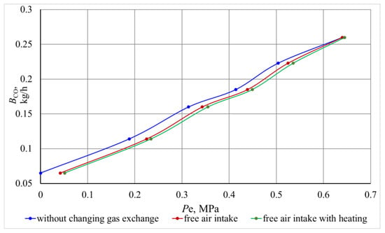
Figure 15.
CO emissions vs. pe with different cylinder shutdown methods (n = 2000 rpm) for the 6Ch9.5/6.98 engine.
The emissions of CO, HC, and NOx were computed by using Formulae (7) and (8). Figure 15 demonstrates that CO emissions were greatest when using the deactivation technique without modifications to the gas distribution system. Conversely, the lowest emissions were seen when allowing the free intake of warm air into the deactivated cylinders. There were slightly greater emissions when utilizing free intake without air heating.
Under typical operating conditions (with a pressure of around 0.3 MPa), the introduction of a gas distribution system resulted in an 8.4% reduction in CO emissions compared to deactivation without any alterations to the system. Additionally, when the system allowed for free air intake without heating, CO emissions were 6.1% lower. At the average load, there was a decrease of 11% in NOx emissions when using heated air intake and a decrease of 8.2% when using unheated air intake.
When comparing the unmodified gas distribution system at medium load to the systems with heated air intake and without heating, there was a reduction of 5.7% in HC emissions with heated air intake and a reduction of 4.2% without heating. The introduction of heated air intake resulted in a 10.8% reduction in CO emissions, whereas without heating, the reduction was 8.1%. The implementation of air heating resulted in a 5.7% reduction in CO2 emissions, whereas without air heating, the reduction was 4.7%. This decrease in emissions may be attributed to the enhanced fuel economy achieved by the utilization of free air intake.
In order to assess the practicality of simultaneously regulating power and deactivating cylinders at partial load and in idle conditions, load characteristics were experimentally obtained for the engine running at 2000 rpm. This was achieved by applying throttling and deactivating certain cylinder groups while keeping the gas distribution system intact. These attributes are shown in the same coordinate system for the sake of comparison.
When reducing engine power by deactivating cylinders, the economizer mode is not used since it results in greater specific fuel consumption compared to operating all cylinders. This requires switching to throttling. Comparisons revealed that running with three cylinders resulted in a maximum torque of about 40% compared to operating with six cylinders (74 Nm vs. 185 Nm). During idle mode, the intake vacuum was about 72 kPa when all cylinders were operating and 53 kPa when just three cylinders were operating. This helped to decrease pumping losses and improve mechanical efficiency.
We analyzed the variations in parameters between the six-cylinder and three-cylinder operations of the 6Ch9.5/6.98 engine (Figure 16). In the case of working on six cylinders, the λ value stays consistently stable, suggesting a uniform air–fuel combination. The initial λ value is greater, suggesting a larger proportion of air to fuel in the mixture. When the engine is running on just three cylinders, it operates with a lower fuel-to-air ratio, which might impact the stability and efficiency of combustion. The pressure indicator on the six cylinders steadily drops as the torque increases. There are three cylinders. The indicator pressure exhibits a more pronounced decline. Increased indicator pressure in six-cylinder mode indicates improved combustion efficiency and greater pressure during combustion. The effective pressure exerted on the six cylinders drops significantly as the torque increases. There are three cylinders. The drop in effective pressure is more pronounced. The six-cylinder mode sustains a greater effective pressure, which suggests superior efficiency and power generation. The hourly fuel consumption falls as torque increases, suggesting enhanced efficiency in the six-cylinder engine. At lower torques, there is increased fuel consumption; however, the rate of decline is comparable to that of the six-cylinder mode as the torque rises. The increased fuel consumption seen in the three-cylinder mode with low torques indicates that it is less efficient under light loads. The concentration of CO grows when torque is applied to the six cylinders. The concentration of carbon monoxide is greater and exhibits a steeper rise in the case of working three cylinders. Increased CO emissions while operating in three-cylinder mode indicates a greater occurrence of incomplete combustion. The CO2 concentration in the six cylinders remains steady, suggesting that the combustion process is efficient. The concentration of CO2 then decreases slightly but remains constant. The small increase in CO2 emissions seen in the six-cylinder mode is a result of full combustion, while the lower emissions in the three-cylinder mode show a reduced amount of fuel being totally burnt. The engine speed decreases somewhat as the torque increases when operating on six cylinders. The engine’s speed decreases more prominently. Increased engine speed in six-cylinder mode indicates an improved capacity to handle heavier loads and maintain stability throughout operation. The mechanical pressure loss experienced by the six cylinders consistently diminishes as the torque increases. The mechanical pressure loss exhibits a steeper decline. Reduced mechanical losses in three-cylinder mode may be attributed to less internal friction and a lower number of moving components. The mechanical efficiency of a system operating with six cylinders improves as the torque rises. The initial mechanical efficiency is lower, but it exhibits a more substantial rise with time. The mechanical efficiency exhibits a more rapid improvement in three-cylinder mode, suggesting less mechanical resistance and enhanced performance under greater torque conditions.
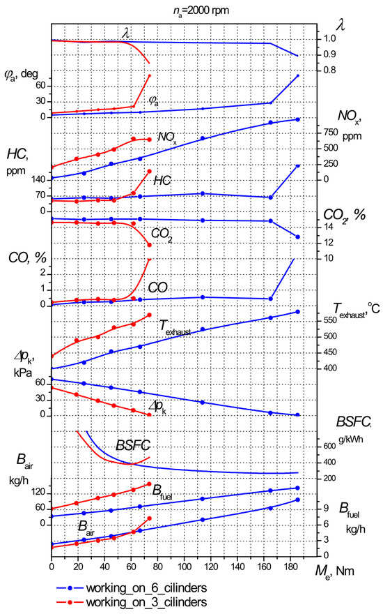
Figure 16.
Comparison of the load characteristics of the 6Ch9.5/6.98 engine.
The functioning of a six-cylinder engine often offers improved combustion efficiency, reduced fuel consumption, and consistent engine speed, making it particularly well-suited for heavier load situations. Operating with three cylinders leads to increased CO emissions and fuel consumption when operating at lower loads. However, it shows enhanced mechanical efficiency and decreased mechanical losses while operating at greater loads. This mode may be desirable in some circumstances when there is a need for less internal friction and mechanical drag. These disparities emphasize the compromises between different modes of operation, aiding in the enhancement of engine efficiency for certain operational situations.
Uncertainty ranges u(y) [44,45] of the components are presented in Table 1. When running on three cylinders, the mean values for most measures, especially Bfuel and Bair, are often greater, suggesting worse efficiency. The Texhaust is elevated while operating with three cylinders, indicating a potential increase in engine load or reduced combustion efficiency. The standard deviation values exhibit greater magnitudes in six-cylinder mode for most parameters, suggesting more variability in the data. Parameters such as Δpk, Bfuel, and Bair exhibit much more fluctuation in six-cylinder mode when compared to three-cylinder mode.

Table 1.
Uncertainty ranges u(y) of the experimental parameters.
The SE numbers tend to be lower when the system is in three-cylinder mode, indicating that the average results are more accurate in this mode since there is less variation. Exceptions worth mentioning include CO, HC, and NOx, where the SE remains substantial, suggesting a certain degree of fluctuation in these measures. The table presents a comprehensive statistical comparison of engine characteristics between operations with six cylinders and operations with three cylinders. When the engine is running on three cylinders, there are higher exhaust temperatures and emissions of CO, HC, and NOx, which suggests that the combustion process is less efficient. There is a higher level of variation in the six-cylinder mode for most measures, suggesting that the three-cylinder mode may provide more reliable performance under the circumstances that were studied. This comparison emphasizes the compromises between the two operating modes, with the six-cylinder mode generally providing more consistent and efficient performance, while the three-cylinder mode may be beneficial in certain situations where decreased mechanical complexity and potentially lower emissions per cylinder are advantageous.
The temperature throughout the working cycle was elevated during three-cylinder operation, as shown by increased exhaust temperatures. The feedback mechanism ensured a fuel–air mixture that closely followed the stoichiometric ratio, as shown by the gas analyzer observations of nitrogen oxide, carbon dioxide, and hydrocarbons. The nitrogen oxide concentrations were elevated during three-cylinder operation as a result of the heightened cycle temperature.
The effectiveness of the combined power regulation approach was measured via experimental investigations. These studies evaluated the hourly petrol consumption in relation to the external load for both three- and six-cylinder operation, across all operating modes. Within the torque range of 0–50 Nm, the three-cylinder operation had 10–0% lower hourly petrol consumption compared to the six-cylinder operation (refer to Figure 17).
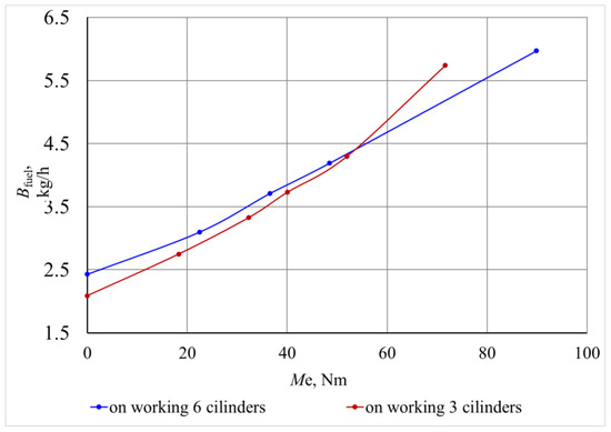
Figure 17.
Hourly fuel consumption vs. effective torque of the 6Ch9.5/6.98 engine on 6 and 3 cylinders (n = 2000 rpm).
The analysis of idle mode found that operating the engine with three cylinders resulted in a reduction in petrol consumption by 32–6% per hour. This reduction was seen throughout a range of crankshaft rotation frequencies from 730 to 3600 rpm, as shown in Figure 18. The findings validate that the combination of power regulation and cylinder deactivation improves fuel efficiency in comparison to conventional throttling methods.
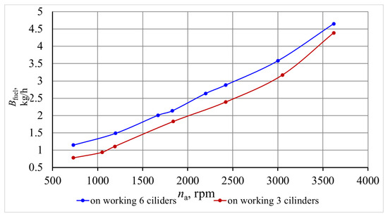
Figure 18.
Hourly fuel consumption vs. idle rotation frequency of the 6Ch9.5/6.98 engine.
The mechanical losses were empirically measured for various cylinder deactivation techniques. The relationship between mechanical losses and throttle opening angle and intake vacuum was determined, revealing notable variations at elevated vacuums often observed during the operation of automobile engines (refer to Figure 19 and Figure 20).
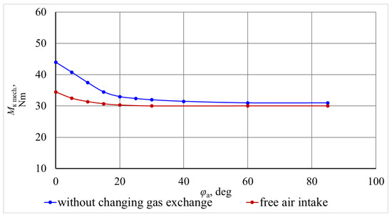
Figure 19.
Mechanical losses vs. throttle opening angle of the 6Ch9.5/6.98 engine (n = 2000 rpm).
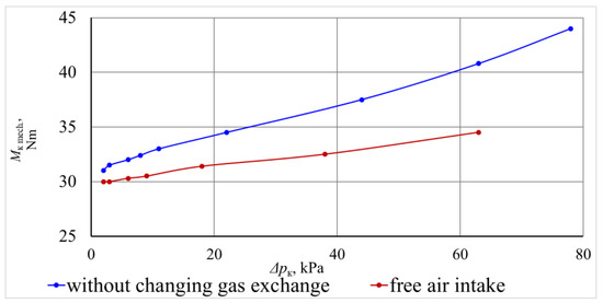
Figure 20.
Mechanical losses vs. intake rarefaction of the 6Ch9.5/6.98 engine (n = 2000 rpm).
The greatest mechanical losses were obtained with the throttle closed and the smallest were obtained with free air intake into the disconnected cylinder group. As can be seen from Figure 19, with a throttle opening angle of more than 45°, its further opening has practically no effect on mechanical losses. Therefore, in subsequent experiments, the vacuum at the intake was measured depending on the throttle opening angle, especially since this parameter can be measured more accurately during engine tests. The dependence of the moment of mechanical losses on the rarefaction at the inlet is shown in Figure 20. As can be seen from the graphs shown, the difference in moments of mechanical losses is greatest at high vacuums, that is, in the modes that are widely used in the operation of automobile engines.
One of the main provisions that was used to develop a methodology for a comparative study of the effect of the method of disconnecting a group of cylinders was that for all three methods that were studied, the composition of the fuel–air mixture, the concentration of fuel in the exhaust, and the hourly fuel consumption were the same, depending on the dilution at the inlet of working cylinders. Therefore, in the process of experimental research, the named indicators were measured depending on the rarefaction when determining the load characteristics for the named three methods of disconnecting the cylinder group. Figure 21 shows the dependence of the coefficient of excess air (λ) on the rarefaction at the intake when determining the load characteristic in the interval from zero to the moment of turning on the economizer. In this interval, the engine works with different ways of shutting off the cylinders.
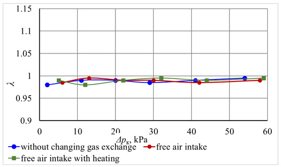
Figure 21.
Excess air coefficient vs. intake rarefaction of the 6Ch9.5/6.98 engine with different cylinder disconnection methods (n = 2000 rpm).
As can be seen from the graph shown, when working on different ways of disconnecting the cylinders, the values of λ practically coincide and vary within 0.98…0.99, which indicates the satisfactory operation of the feedback and the identity of the mixture compositions in all ways of disconnecting the group of cylinders. Confirmation that the methods of disconnecting the cylinders that were studied do not affect the combustion process in the working cylinders is dependent on the concentration of exhaust.
As can be seen from Figure 22, the concentration of CO is quite close for all methods of disconnecting the cylinders (0.35–0.55%), and the nature of the dependence is the same as the rarefaction increases.
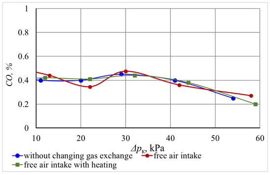
Figure 22.
CO concentration in the exhaust vs. intake rarefaction of the 6Ch9.5/6.98 engine with different three-cylinder disconnection methods (n = 2000 rpm).
Figure 23 shows the dependence of CO2 concentrations in the exhaust, which were obtained for different methods of cylinder shutdown, from which it can be seen that in the entire range of loads, with the exception of the economizer mode, the CO2 concentrations are in the range of 14.5…14.7%, which is within the limits of the accurate measurement of this substance.
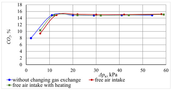
Figure 23.
CO2 concentration in exhaust vs. intake rarefaction of the 6Ch9.5/6.98 engine with different three-cylinder disconnection methods (n = 2000 rpm).
The mass of SO emissions depends on their concentration in the exhaust and the hourly consumption of fuel and air. With the same values of the air excess coefficient, the mass emissions of the fuel tank depend only on the hourly fuel consumption. The dependence of the hourly fuel consumption on different ways of disconnecting the cylinders is shown in Figure 24. Hourly fuel consumption is practically the same when operating in the entire load range, except for the economizer mode. Thus, it can be stated that according to the results of experimental studies, with all of the investigated ways of disconnecting a group of cylinders, the indicators of the work process in working cylinders are the same, and the positions adopted in theoretical studies are correct.
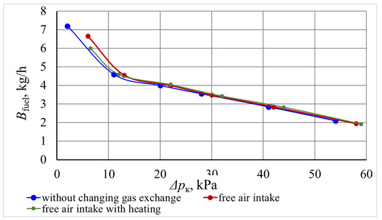
Figure 24.
Hourly fuel consumption vs. intake rarefaction of the 6Ch9.5/6.98 engine with different three-cylinder disconnection methods (n = 2000 rpm).
To compare the calculated and experimental indicators, the hourly gasoline consumption of the 6Ch9.5/6.98 engine was measured from the effective torque during operation with an unchanged gas distribution system and with free air intake into the disconnected cylinders (see Figure 25). When using the method with free air intake without heating the disconnected cylinders, gasoline savings of 10.8–0.0% were obtained within the range of torque change of 0–50 Nm.
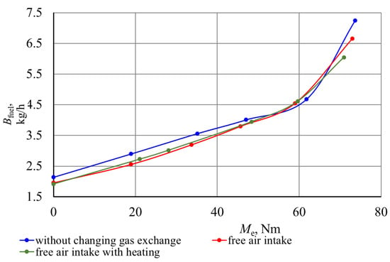
Figure 25.
Hourly fuel consumption vs. effective torque of the 6Ch9.5/6.98 engine with different cylinder shutdown methods (n = 2000 rpm).
The obtained results of experimental studies are quite close to the results of theoretical studies, in which it is shown that disconnection of a group of cylinders with free intake into a disconnected group of heated air cylinders allows for improved fuel efficiency in comparison with disconnection without changes in the gas exchange system by 1.5…13.5%; if the air is not heated, the saving is 1.5…10.5%.
5. Conclusions
- In this study, we discovered that disabling a set of cylinders results in enhanced fuel economy, mostly because of the heightened indicator and mechanical efficiency while running on three cylinders. The research also revealed numerous cylinder deactivation techniques that have varying effects on the engine’s fuel economy and environmental performance while running with a reduced number of cylinders.
- Based on prior research, viable techniques for disabling a set of cylinders to implement a combined power control mechanism in spark-ignition engines were validated. These approaches include ceasing the flow of fuel without making any changes to the intake and gas distribution systems and halting the delivery of fuel while permitting unrestricted airflow into the deactivated cylinders at the surrounding temperature. Approach for Computational Studies:A comprehensive approach for performing computational investigations on the effects of cylinder deactivation techniques was established. The approach presupposes that the operational procedure in active cylinders stays consistent and reliant on the intake vacuum for all examined techniques. Therefore, performance measures such as stated efficiency, air and fuel consumption, and pollutant concentrations remain constant regardless of the techniques used. The variations in engine performance indicators seen with various deactivation techniques may be attributed mostly to mechanical losses, which were assessed using experimental data.
- Empirical investigations have shown that the operational parameters in active cylinders stay constant regardless of the deactivation techniques examined. By maintaining homogeneity, it becomes possible to compare deactivation techniques purely on the basis of mechanical losses, which in turn enhances the accuracy of such comparisons.
- The dependencies for calculating mechanical efficiency, based on the mechanical loss pressure and intake vacuum of the deactivated cylinders, were defined. The dependencies were found empirically for each deactivation technique. The reliability of the relationships was assessed by comparing the estimated and empirically measured specific fuel consumption versus load parameters.
- Experimental tests have shown that the deactivation strategy that leaves the intake and gas distribution systems unchanged results in the greatest mechanical loss pressure. The other two systems exhibited markedly reduced mechanical loss pressure, with negligible differences between them.
- In this study, we analyzed the fuel efficiency of several cylinder deactivation strategies by analyzing the particular effective fuel consumption relative to the external load, as measured by mean effective pressure. The engine had the greatest specific fuel economy while disabling cylinders without altering the intake system. The use of a technique that enables unrestricted airflow into inactive cylinders at the surrounding temperature resulted in fuel efficiency improvement ranging from 1.5% to 10.5%. Tests conducted on the 6Ch9.5/6.98 engine revealed that using free air intake resulted in a reduction in fuel consumption by as much as 10.8% compared to the original intake system. This improvement was seen throughout a torque range of 0 to 51 Nm.
- In addition, we estimated the mass emissions of each pollutant per unit of time and per unit of labor completed, as well as the overall emissions compared to CO. For a typical load condition (with a mean effective pressure of 0.3 MPa), the reduction in pollutants achieved by using techniques that include free air intake (with and without heating) was substantial when compared to the unmodified intake system. CO emissions dropped by 8.4% and 6.1%, NOx emissions dropped by 11.0% and 8.2%, HC emissions dropped by 5.7% and 4.2%, and total emissions relative to CO dropped by 10.8% and 8.1%. CO2 emissions also had reductions of 5.7% and 4.7%.
- According to theoretical and experimental research, the most appropriate approach for practical use is to cut off the fuel supply while permitting unrestricted air intake into the deactivated cylinders at the surrounding temperature. Although heating the air may enhance engine performance to some extent, it necessitates the use of supplementary equipment, which may not be feasible in every situation.
- In this study, we conducted a comprehensive assessment of several techniques for cylinder deactivation in a spark-ignition engine, emphasizing the advantages of enhanced fuel economy and decreased pollutants. The recommended approach, which involves cutting off the fuel supply while allowing air to enter the deactivated cylinders, provides a practical and efficient solution. This technique achieves a balance between enhancing performance and being easy to execute.
Author Contributions
Conceptualization, J.M., S.R., Y.G., Y.S., O.S., A.R. and D.T.; methodology, J.M., S.R., Y.G., Y.S., O.S., A.R. and D.T.; software, J.M., S.R., Y.S., O.S. and D.T.; validation, J.M., S.R., Y.G., Y.S., O.S., A.R. and D.T.; formal analysis, J.M., Y.S., O.S., A.R. and D.T.; investigation, J.M., S.R., Y.G., Y.S., O.S., A.R. and D.T.; resources, J.M., S.R., Y.G., Y.S., O.S., A.R. and D.T.; data curation, J.M., S.R., Y.G., Y.S., O.S., A.R. and D.T.; writing—original draft preparation, J.M., S.R., Y.G., Y.S., O.S., A.R. and D.T.; writing—review and editing, J.M., S.R., Y.G., Y.S., O.S., A.R. and D.T.; visualization, J.M., S.R., Y.G., Y.S., O.S., A.R. and D.T.; supervision, J.M., Y.G. and Y.S.; project administration, J.M., Y.G. and Y.S.; funding acquisition, J.M. and A.R. All authors have read and agreed to the published version of the manuscript.
Funding
This research received no external funding.
Data Availability Statement
Data can be provided by the authors upon request.
Acknowledgments
We recognize the productive partnership between Vilnius Gediminas Technical University (Lithuania) and the National Transport University (Ukraine), which has greatly enhanced our scientific pursuits.
Conflicts of Interest
The authors declare no conflicts of interest.
Nomenclature
| BSFC | Brake-specific fuel consumption |
| CO | Carbon monoxide |
| CO2 | Carbon dioxide |
| EEC | Engine efficiency coefficient |
| EGR | Exhaust gas recirculation |
| Hu | Lower heat of combustion, MJ/kg |
| HC | Hydrocarbons |
| ICE | Internal combustion engines |
| l0 | The theoretically necessary amount of air for the combustion of 1 kg of fuel, kg/kg |
| NOx | Nitrogen oxides |
| pa | Pressure in the engine cylinder at the end of the intake |
| pi | Indicator pressure |
| pe | Effective pressure |
| pM | Mechanical losses |
| p0 | Pressure at the engine inlet, kPa |
| SIE | Spark-ignition engines |
| SO | Sulfur oxide |
| T0 | Engine inlet temperature, °K |
| VVL | Variable valve lift |
| VVT | Variable valve timing |
| w | The average speed of gas movement in the passage section of the valve, m/s |
| Δpa | Losses in the intake system |
| Δpk | Vacuum at the intake |
| ΔT | Heating of the fresh charge in the intake process, °K |
| β | The decay rate of the fresh charge in the considered section |
| ηi | Indicator EEC when the cylinders are disconnected: they are classified as working cylinders |
| ηm | Mechanical EEC engine |
| ηv | Filling coefficient |
| λ | Coefficient of excess air |
| λg | Coefficient of cleaning the combustion chamber of residual gases |
| λ1 | Recharge coefficient |
| ρ0 | Charge density at the engine inlet, kg/m3 |
| ρk | Air density, kg/m3 |
| ψ | The coefficient that takes into account the difference in the heat capacity of the fresh mixture and the mixture at the end of the inlet |
| ξIN | Coefficient of hydraulic resistance of the intake system referring to its highest section |
References
- Andrych-Zalewska, M.; Chlopek, Z.; Pielecha, J.; Merkisz, J. Investigation of Exhaust Emissions from the Gasoline Engine of a Light Duty Vehicle in the Real Driving Emissions Test. Eksploat. I Niezawodn. Maint. Reliab. 2023, 25, 165880. [Google Scholar] [CrossRef]
- Gęca, M.S.; Rybak, A.; Hunicz, J. A Simulation Study into the Atkinson Cycle Engine Utilizing Adjustable Crank Mechanism. IOP Conf. Ser. Mater. Sci. Eng. 2018, 421, 042021. [Google Scholar] [CrossRef]
- Wasiak, A.; Orynycz, O.; Tucki, K.; Świć, A. Hydrogen Enriched Hydrocarbons as New Energy Resources—As Studied by Means of Computer Simulations. Adv. Sci. Technol. Res. J. 2022, 16, 78–85. [Google Scholar] [CrossRef] [PubMed]
- Zhu, C.; Samuel, O.D.; Elboughdiri, N.; Abbas, M.; Saleel, C.A.; Ganesan, N.; Enweremadu, C.C.; Fayaz, H. Artificial Neural Networks vs. Gene Expression Programming for Predicting Emission & Engine Efficiency of SI Operated on Blends of Gasoline-Methanol-Hydrogen Fuel. Case Stud. Therm. Eng. 2023, 49, 103109. [Google Scholar] [CrossRef]
- Tucki, K.; Orynycz, O.; Wasiak, A.; Świć, A.; Mieszkalski, L.; Mruk, R.; Gola, A.; Słoma, J.; Botwińska, K.; Gawron, J. A Computer Tool Using OpenModelica for Modelling CO2 Emissions in Driving Tests. Energies 2022, 15, 995. [Google Scholar] [CrossRef]
- Guzzella, L.; Onder, C. Introduction to Modeling and Control of Internal Combustion Engine Systems; Springer Science & Business Media: Berlin, Germany, 2009; ISBN 978-3-642-10775-7. [Google Scholar]
- Leach, F.; Kalghatgi, G.; Stone, R.; Miles, P. The Scope for Improving the Efficiency and Environmental Impact of Internal Combustion Engines. Transp. Eng. 2020, 1, 100005. [Google Scholar] [CrossRef]
- Kutlar, O.A.; Arslan, H.; Calik, A.T. Methods to Improve Efficiency of Four Stroke, Spark Ignition Engines at Part Load. Energy Convers. Manag. 2005, 46, 3202–3220. [Google Scholar] [CrossRef]
- Szybist, J.P.; Busch, S.; McCormick, R.L.; Pihl, J.A.; Splitter, D.A.; Ratcliff, M.A.; Kolodziej, C.P.; Storey, J.M.E.; Moses-DeBusk, M.; Vuilleumier, D.; et al. What Fuel Properties Enable Higher Thermal Efficiency in Spark-Ignited Engines? Prog. Energy Combust. Sci. 2021, 82, 100876. [Google Scholar] [CrossRef]
- Fontana, G.; Galloni, E. Variable Valve Timing for Fuel Economy Improvement in a Small Spark-Ignition Engine. Appl. Energy 2009, 86, 96–105. [Google Scholar] [CrossRef]
- Leone, T.G.; Anderson, J.E.; Davis, R.S.; Iqbal, A.; Reese, R.A.; Shelby, M.H.; Studzinski, W.M. The Effect of Compression Ratio, Fuel Octane Rating, and Ethanol Content on Spark-Ignition Engine Efficiency. Environ. Sci. Technol. 2015, 49, 10778–10789. [Google Scholar] [CrossRef]
- Duan, X.; Feng, L.; Liu, H.; Jiang, P.; Chen, C.; Sun, Z. Experimental Investigation on Exhaust Emissions of a Heavy-Duty Vehicle Powered by a Methanol-Fuelled Spark Ignition Engine under World Harmonized Transient Cycle and Actual on-Road Driving Conditions. Energy 2023, 282, 128869. [Google Scholar] [CrossRef]
- Wang, C.; Wang, X.; Wang, H.; Xu, Y.; Ge, Y.; Tan, J.; Hao, L.; Wang, Y.; Zhang, M.; Li, R. Co-Optimizing NOx Emission and Power Output of a Natural Gas Engine-ORC Combined System through Neural Networks and Genetic Algorithms. Energy 2024, 289, 130072. [Google Scholar] [CrossRef]
- Lei, Q.; Feng, H.; Liu, C.; Jia, B.; Zhang, Z.; Zuo, Z. Numerical Investigation of the Impact of Dual Spark Plug Coordinated Ignition Strategy on the Combustion Process in a Free Piston Engine Generator. Energy 2024, 290, 129880. [Google Scholar] [CrossRef]
- The U.S. Environmental Protection Agency (EPA) and U.S. Department of Energy (DOE) 2023 Fuel Economy Guide. Available online: https://www.fueleconomy.gov/feg/pdfs/guides/feg2024.pdf (accessed on 1 July 2024).
- Bereczky, A. The Past, Present and Future of the Training of Internal Combustion Engines at the Department of Energy Engineering of BME. In Vehicle and Automotive Engineering, Proceedings of the JK2016, Miskolc, Hungary, January 2017; Jarmai, K., Bollo, B., Eds.; Springer International Publishing: Berlin, Germany, 2017; pp. 225–234. [Google Scholar]
- Kryshtopa, S.; Górski, K.; Longwic, R.; Smigins, R.; Kryshtopa, L. Increasing Parameters of Diesel Engines by Their Transformation for Methanol Conversion Products. Energies 2021, 14, 1710. [Google Scholar] [CrossRef]
- Žvirblis, T.; Hunicz, J.; Matijošius, J.; Rimkus, A.; Kilikevičius, A.; Gęca, M. Improving Diesel Engine Reliability Using an Optimal Prognostic Model to Predict Diesel Engine Emissions and Performance Using Pure Diesel and Hydrogenated Vegetable Oil. Eksploat. I Niezawodn. Maint. Reliab. 2023, 25, 174358. [Google Scholar] [CrossRef]
- Žvirblis, T.; Vainorius, D.; Matijošius, J.; Kilikevičienė, K.; Rimkus, A.; Bereczky, Á.; Lukács, K.; Kilikevičius, A. Engine Vibration Data Increases Prognosis Accuracy on Emission Loads: A Novel Statistical Regressions Algorithm Approach for Vibration Analysis in Time Domain. Symmetry 2021, 13, 1234. [Google Scholar] [CrossRef]
- Gutarevych, Y.; Mateichyk, V.; Matijošius, J.; Rimkus, A.; Gritsuk, I.; Syrota, O.; Shuba, Y. Improving Fuel Economy of Spark Ignition Engines Applying the Combined Method of Power Regulation. Energies 2020, 13, 1076. [Google Scholar] [CrossRef]
- Gutarevych, Y.; Shuba, Y.; Matijošius, J.; Karev, S.; Sokolovskij, E.; Rimkus, A. Intensification of the Combustion Process in a Gasoline Engine by Adding a Hydrogen-Containing Gas. Int. J. Hydrogen Energy 2018, 43, 16334–16343. [Google Scholar] [CrossRef]
- Sznitman, A.-S. Upper Bound on the Disconnection Time of Discrete Cylinders and Random Interlacements. Ann. Probab. 2009, 37, 1715–1746. [Google Scholar] [CrossRef]
- Sznitman, A.-S. How Universal Are Asymptotics of Disconnection Times in Discrete Cylinders? Ann. Probab. 2008, 36, 1–53. [Google Scholar] [CrossRef]
- Moldavian, A.; Dubinin, Y.; Polyanskyi, O.; Potapov, M.; Poltavskyi, M.; Krasnokutskyi, M.; Moлoдан, A.O.; Дубінін, Є.O.; Пoлянський, O.C.; Пoтапoв, M.M.; et al. Changes in Engines Energy Indicators When the Cylinders Are Disconnected in the Unloaded Mode of Operation. 2023. [Google Scholar] [CrossRef]
- Aliramezani, M.; Koch, C.R.; Shahbakhti, M. Modeling, Diagnostics, Optimization, and Control of Internal Combustion Engines via Modern Machine Learning Techniques: A Review and Future Directions. Prog. Energy Combust. Sci. 2022, 88, 100967. [Google Scholar] [CrossRef]
- Tamassia, R.; Tollis, I.G. Representations of Graphs on a Cylinder. SIAM J. Discret. Math. 1991, 4, 139–149. [Google Scholar] [CrossRef]
- Heywood, J.B. Internal Combustion Engine Fundamentals, 2nd ed.; McGraw-Hill Education: New York, NY, USA, 2018; ISBN 978-1-260-11610-6. [Google Scholar]
- Isermann, R. Engine Modeling and Control: Modeling and Electronic Management of Internal Combustion Engines; Springer: Berlin/Heidelberg, Germany, 2014; ISBN 978-3-642-39933-6. [Google Scholar]
- Sher, E. (Ed.) Handbook of Air Pollution from Internal Combustion Engines: Pollutant Formation and Control; Academic Press: Boston, UK, 1998; ISBN 978-0-12-639855-7. [Google Scholar]
- Piaszyk, J. Animal Fat (Tallow) as Fuel for Stationary Internal Combustion Engines; School of Mechanical Engineering, The University of Birmingham: Birmingham, UK, 2012. [Google Scholar]
- Heywood, J.B. Internal Combustion Engine Fundamentals; McGraw-Hill Series in Mechanical Engineering; McGraw-Hill: New York, NY, USA, 1988; ISBN 978-0-07-028637-5. [Google Scholar]
- Lijewski, P.; Merkisz, J.; Fuc, P.; Ziolkowski, A.; Rymaniak, L.; Kusiak, W. Fuel Consumption and Exhaust Emissions in the Process of Mechanized Timber Extraction and Transport. Eur. J. For. Res. 2017, 136, 153–160. [Google Scholar] [CrossRef]
- Fuć, P.; Lijewski, P.; Sokolnicka, B.; Szymlet, N.; Siedlecki, M.; Dębowski, T. Impact of Using a Filter in a Direct Gasoline Injection Engine Exhaust System on the Emitted Particle Mass and Number. J. Konbin 2020, 50, 61–76. [Google Scholar] [CrossRef]
- Stone, R. Solutions Manual for Introduction to Internal Combustion Engines; Macmillan Education UK: London, UK, 1999; ISBN 978-0-333-79307-7. [Google Scholar]
- Alagumalai, A. Internal Combustion Engines: Progress and Prospects. Renew. Sustain. Energy Rev. 2014, 38, 561–571. [Google Scholar] [CrossRef]
- Pulkrabek, W.W. Engineering Fundamentals of the Internal Combustion Engine, 2nd Ed. J. Eng. Gas Turbines Power 2004, 126, 198. [Google Scholar] [CrossRef]
- Basshuysen, R.V.; Schaefer, F. Internal Combustion Engine Handbook; SAE International: Warrendale, PA, USA, 2016; ISBN 978-0-7680-8024-7. [Google Scholar]
- Reitz, R.D.; Ogawa, H.; Payri, R.; Fansler, T.; Kokjohn, S.; Moriyoshi, Y.; Agarwal, A.; Arcoumanis, D.; Assanis, D.; Bae, C.; et al. IJER Editorial: The Future of the Internal Combustion Engine. Int. J. Engine Res. 2020, 21, 3–10. [Google Scholar] [CrossRef]
- National Transport University, Kyiv, Ukraine; Y.G.; S.R.; State Entreprise «State Road Transport Research Institute», Kyiv, Ukraine INFLUENCE OF THE COMBINED METHOD OF POWER REGULATION IMPLEMENTATION WAY ON SPARK IGNITION ENGINE’S MECHANICAL LOSSES AND FUEL ECONOMY. NTUB 2022, 1, 149–158. [CrossRef]
- Taylor, A.M.K.P. Science Review of Internal Combustion Engines. Energy Policy 2008, 36, 4657–4667. [Google Scholar] [CrossRef]
- Reitz, R.D. Directions in Internal Combustion Engine Research. Combust. Flame 2013, 160, 1–8. [Google Scholar] [CrossRef]
- Matsuura, M.; Nakamori, M.; Honda, S.; Ishida, Y.; Nakanishi, T. Internal Combustion Engine. US 4741299 21 January 1986. [Google Scholar]
- Rakopoulos, C.D.; Giakoumis, E.G. Second-Law Analyses Applied to Internal Combustion Engines Operation. Prog. Energy Combust. Sci. 2006, 32, 2–47. [Google Scholar] [CrossRef]
- Evaluation of Measurement Data—Supplement 1 to the “Guide to the Expression of Uncertainty in Measurement”—Propagation of Distributions Using a Monte Carlo Method. Available online: https://www.bipm.org/utils/common/documents/jcgm/JCGM_101_2008_E.pdf (accessed on 27 April 2020).
- Evaluation of Measurement Data—Guide to the Expression of Uncertainty in Measurement. Available online: https://www.bipm.org/utils/common/documents/jcgm/JCGM_100_2008_E.pdf (accessed on 27 April 2020).
Disclaimer/Publisher’s Note: The statements, opinions and data contained in all publications are solely those of the individual author(s) and contributor(s) and not of MDPI and/or the editor(s). MDPI and/or the editor(s) disclaim responsibility for any injury to people or property resulting from any ideas, methods, instructions or products referred to in the content. |
© 2024 by the authors. Licensee MDPI, Basel, Switzerland. This article is an open access article distributed under the terms and conditions of the Creative Commons Attribution (CC BY) license (https://creativecommons.org/licenses/by/4.0/).