Abstract
The increasingly extensive use of non-linear loads, mostly including static power converters, in large industry, commercial, and domestic applications, as well as the spread of renewable energy sources in distribution-generated units, make the use of the most efficient power quality improvement systems a current concern. The use of active power filters proved to be the most advanced solution with the best compensation performance for harmonics, reactive power, and load unbalance. Thus, issues related to improving the power quality through active power filters are very topical and addressed by many researchers. This paper presents a topical review on the shunt active power filters in three-phase, three-wire systems. The power circuit and configurations of shunt active filtering systems are considered, including the multilevel topologies and use of advanced power semiconductor devices with lower switching losses and higher switching frequencies. Several compensation strategies, reference current generation methods, current control techniques, and DC-voltage control are pointed out and discussed. The direct power control method is also discussed. New advanced control methods that have better performance than conventional ones and gained attention in the recent literature are highlighted. The current state of renewable energy sources integration with shunt active power filters is analyzed. Concerns regarding the optimum placement and sizing of the active power filters in a given power network to reduce the investment costs are also presented. Trends and future developments are discussed at the end of this paper. For a rigorous substantiation, more than 250 publications on this topic, most of them very recent, constitute the basis of bibliographic references and can assist readers who are interested to explore the subject in greater detail.
1. Introduction
Increasingly in recent years, large industries and electric utilities are very concerned about the ever-widening existence of nonlinear loads in their power systems. Nonlinear loads are commonly used in general industrial, commercial, and consumer applications, such as variable-speed drives, arc furnaces, line-frequency converters, industrial saturated equipment, and domestic loads. More than 70% of the electricity supplied to consumers in countries with modern industrial technology involves the use of power electronics devices as the main nonlinear load [1]. Supported by government policies in recent years, and due to advancements in technology, the development and implementation of renewable energy sources with a significant impact on power quality has increased too. The nonlinear loads mainly distort the supply current by the injected harmonics, leading to increased losses, reduced power factor, and load unbalance in power distribution systems.
Therefore, finding and implementing solutions of high performance to improve the power quality, as well as new control methods with better performance in existing systems, is very topical. The classic low-cost passive filters used to compensate harmonics and reactive power have the shortcomings of being bulky in size and not adapting to changes in system parameters. Moreover, their performance in harmonic filtering is limited.
It is widely accepted that the use of active power filters (APFs), which are power electronic converter-based devices, is the most advanced solution that leads to the best compensation performance of harmonics, reactive power, and load unbalance. Among these, the three-phase, three-wire shunt active power filter (SAPF) topology is the most often adopted solution to improve the power quality in electrical power systems. It is connected in parallel with the nonlinear load and injects a proper compensating current in the point of common coupling (PCC) generated according to the desired compensation strategy.
The use of SAPF has gained a lot of attention, both in technical discussions as well as in many topical review papers [2,3,4,5,6,7,8] and international regulations related to power quality measurement and harmonic control [9,10,11]. Currently, there is a proven interest in this topic, and a lot of achievements in many aspects regarding the development of three-phase shunt active power filtering systems have been reported.
Regarding the power circuit configurations of three-phase SAPF, besides the traditional SAPF scheme, other configurations have been proposed, such as SAPF with injection circuit based on parallel/series resonance of LC filter or based on double resonance injection branch for high-capacity applications [2,3,12,13,14].
By using the SAPF topology with two parallel inverters connected together on the AC line and sharing the same DC-link capacitor, an accurate compensation for high-power applications can be obtained. Moreover, the number of SAPF output voltage levels can be increased, and harmonic distortion is lower compared to that of the conventional configuration [15,16,17,18,19].
In order to reduce the voltage stress in the inverter’s power semiconductor devices and to improve the current waveform at the AC-side, multilevel topologies of SAPF are used in high voltage and large power applications instead of the classical two-level topology. In most SAPF applications, the number of inverter levels is limited to three, in the idea of limiting the effects of voltage imbalance among the DC-link capacitors [20]. The three topologies of three-level inverters widely used for SAPFs are neutral-point diode clamped (NPC), flying capacitor (FC), and cascaded H-bridge (CHB) [20]. Among them, the three-level NPC topology is the most used due to the minimum usage of DC capacitors, leading to smaller physical size and fewer problems related to the DC-link voltage imbalance [20,21,22,23,24,25].
In recent years, the development of power electronics technology has made it possible to use new power semiconductor devices in the power circuit configuration of the SAPF, such as SiC (silicon carbide) and GaN (gallium nitride) transistors switched at very high frequencies with lower switching losses than the commonly used IGBTs (Insulated-Gate Bipolar Transistors) [18,26,27,28,29,30].
A very important aspect, which essentially determines the performance of the SAPF system with current control, is the generation of reference currents. Although there are many new contributions that fall into the time-domain and frequency-domain methods for the reference current calculation, most ideas and contributions in recent years refer to methods from the so-called soft-computing category [2,31,32,33]. They are either learning techniques or techniques inspired by natural phenomena [2,8,20,32,34,35,36,37,38,39,40,41,42,43].
For the current control, various control techniques have been proposed. Starting from the classic and simple control with fixed hysteresis band [2,39,44,45,46,47,48,49,50], improved adaptive-band hysteresis algorithms appeared and also model predictive control [2,19,20,25,34,51,52], deadbeat control [2,34,53,54,55,56], sliding mode control [2,34,57,58,59,60,61], proportional-resonant control [54,56,62,63,64,65,66,67], repetitive control [2,18,25,26,27,62,68,69,70,71,72], multi-loop control [73,74,75,76,77,78], multiresonant control [79,80,81,82,83], or fuzzy logic-based control techniques [84,85,86,87].
A frequently adopted control alternative in active power filtering systems is the so-called direct power control (DPC), which involves the direct control of instantaneous active and reactive powers instead of current control. As the conventional DPC is based on a predefined switching table and hysteresis controllers leading to variable switching frequency, improved versions of DPC have been proposed over time [8,55,57,88,89,90,91,92,93,94,95].
Several modulation strategies can be used to generate the control pulses for the power semiconductor devices, starting with the carrier-based sine-triangle PWM, which is the typical PWM technique, and then with the newer technique named Space Vector Pulse Width Modulation and its different variations [2,41,96,97,98].
In the most common SAPF structures, which have a voltage source inverter, an important aspect for proper operation is keeping the voltage constant across the capacitor on the DC side of the inverter to cope with the power losses. In most cases, using a proportional-integral (PI) controller is satisfactory [48,54,55,57,66,69,95,99,100,101,102,103,104,105,106,107,108]. However, there are other types of controllers proposed in recent years in the literature, such as PI/fuzzy [49,109], fuzzy [49,87,110], PSO/PI [39], synergetic [111], bi-sliding mode PI [112], ANN [42], sliding mode [99,113,114], and capacitor energetic model-based controller [115].
The use of renewable energy sources has gained a lot of interest lately, and, along with their spread, the topic of renewable energy sources integration with SAPF became very attractive [8,32,38,116,117,118,119,120,121,122]. An exhaustive review of control techniques of SAPF, maximum power point tracking, and renewable energy sources integrated with SAPF is provided in [32]. An overview of the solar-powered SAPF using Z-source inverters is presented in [8]. To improve the performance of a photovoltaic integrated SAPF, a novel technique based on machine learning algorithms is proposed in [38].
Other specific applications of using SAPF to improve the power quality are the electric vehicles (EVs) charging stations [123], shipboard power systems [124,125,126,127], and electric railway systems [128,129].
Optimizing the sizing and placement of SAPF in the power network is another current issue [1,4,43]. A review paper, i.e., [4], summarizes the optimization methods used in the area of APF sizing and placement and the goal functions and constraints related to the optimization problem. Some recent approaches in the field of allocation of APFs in distribution networks are centralized in [43].
This paper is intended to provide a comprehensive and up-to-date review on the use of SAPFs in three-phase, three-wire systems in order to highlight the existing achievements and cover the main shortcomings found in the literature. A survey based on various recent articles has been carried out and presented in the following sections: Section 2 outlines the power circuit configurations of the three-phase SAPFs. Then, Section 3 is devoted to the general objectives of active power filtering. Section 4 presents the methods used for reference current generation in direct current control and indirect current control, while Section 5 describes the most used current control techniques and highlights their strengths and weaknesses. The main modulation strategies to generate the gating signals for the inverter’s power semiconductor devices are presented in Section 6. The DC-voltage control is then discussed in Section 7. Section 8 provides basic ideas and trends of using the direct power control strategy in the control of three-phase SAPFs. In Section 9, the integration of renewable energy sources with SAPFs is discussed. After addressing the issue of optimizing the sizing and placement of SAPFs in Section 10, the trends and future developments are formulated in the next section. Finally, the main conclusions are presented.
2. Power Circuit Configurations
The power circuit configurations of SAPFs can be based on two-level topologies or multi-level topologies.
2.1. Two-Level Topologies
Most SAPFs use a standard two-level topology. Basically, two types of static converters are used in the power circuit configurations of a two-level SAPF, i.e., voltage source inverter (VSI) (Figure 1a) and current source inverter (CSI) (Figure 1b) [2,5,130].
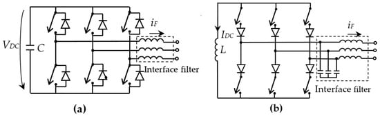
Figure 1.
Types of static converters used in the structure of SAPF: (a) voltage source inverter and (b) current source inverter.
The VSI-based structure uses an electrolytic capacitor on the DC side as energy storage, and the inverter bridge consists of six controllable switches (usually IGBTs) with antiparallel diodes. A coupling filter is placed between the inverter output and the power supply to ensure a good current dynamic and sufficiently smooth the SAPF’s output currents affected by the switching harmonics. This filter is commonly of first order (an inductance L), but a third-order structure (of LCL type) can be used too [72,74,75,131].
On the other hand, the CSI-based structure uses an inductor on the DC side as energy storage, the voltage being able to take both polarities. In the inverter structure, to ensure the blocking capability of the reverse voltage, diodes are connected in series with the conventional switching power devices such as IGBTs, which have a low reverse voltage blocking capability. Instead of the series connection of diodes, the use of the reverse blocking-insulated gate bipolar transistors (RB–IGBTs) is an alternative. Also, when gate turn-off thyristors (GTOs) are used, the series diodes are no longer needed. The inverter is connected to the power supply through a second-order filter of LC type to filter the inverter’s switching harmonics.
Table 1 illustrates a comparison between VSI-based SAPFs and CSI-based SAPFs.

Table 1.
Comparison of three-phase VSI-based SAPF and CSI-based SAPF.
Due to the advantages arising mainly from the use of a capacitor on the DC side, the VSI-based structure is preferred in practical applications of SAPF. There are also applications of using the CSI-based structure [73,132,133].
For coping with high power requirements, the solution of using parallel inverters is proposed in the literature. Figure 2 illustrates the topology of a three-phase SAPF with two parallel interleaved inverters sharing the same DC capacitor [15,16,17,18,19]. Through this configuration, the size of the linkage inductors and the switching stress in the DC capacitor are reduced [15,16,17]. If the grid current ripple is imposed, it is proven that the interleaving leads to a reduction of the line inductors to almost 70% compared to the case of a typical single-unit inverter [16,17]. In [18], an interleaved SAPF with SiC-MOSFET power semiconductor devices was proposed to accurately compensate harmonics with low output switching ripple and low output filter by shifting phase. Moreover, when an interleaved modulation technique is used, a multilevel voltage is generated, and a reduction of DC-link losses is obtained [19]. Consequently, the harmonic distortions are reduced when compared to the conventional topology.

Figure 2.
Topology of SAPF with two parallel interleaved inverters sharing the same DC capacitor.
2.2. Multilevel Topologies
In the case of medium/high voltage and large power applications, the multilevel topologies of SAPF have been proven to be more advantageous than the classic topology with two levels in terms of switching losses, power switch voltage stress, and AC current waveform [5,20,21,22,23,24,25,134,135,136,137,138,139,140]. Because the higher the inverter level number, the higher the number of power semiconductor devices and DC capacitors, and the complexity of the control system is increased (including the need for specific DC voltage balancing techniques), in most SAPF applications, multilevel inverters with more than three levels are used less often. Thus, the problems related to voltage imbalance among the DC-link capacitors are greatly reduced [20].
The most used three-phase, three-wire, three-level topology of inverters used for SAPFs is neutral-point diode clamped (NPC) (Figure 3a) [5,20,21,22,23,24,25,134,135,136]. Other topologies are flying capacitor (FC) (Figure 3b) [20,137,138] and cascaded H-bridge (CHB) (Figure 3c) [20,139,140]. The three-level NPC-based structure is robust and requires only two DC-link capacitors, so that the voltage imbalance problems are the least and the physical size is smaller. Instead, six clamping diodes are required. In the three-level FC-based structure, there are three clamping capacitors, leading to bulky size, high development costs, and complex voltage balancing and control algorithms. The CHB structure is modular, therefore simple, and the associate control is also simpler, but its applications are limited due to the need to use separate DC sources [20].
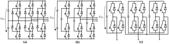
Figure 3.
The three topologies of the most used three-phase, three-wire, three-level SAPFs: (a) NPC, (b) FC, and (c) CHB.
2.3. New Power Semiconductor Devices
With the technological evolution of recent years in the field of power semiconductor devices, new components, such as SiC (silicon carbide) and GaN (gallium nitride), could be used in the high-frequency SAPFs. Compared with the traditional silicon (Si)-based semiconductor devices, SiC- and GaN-based MOSFETs have higher switching frequencies, lower switching losses, and better temperature tolerance.
There are very few publications in this regard in recent years [18,26,27,28,29,30,141,142,143,144,145]. In [26], the proposed SAPF is based on SiC-MOSFET, having a switching frequency increased to 50 kHz and improved performance of harmonic extraction and current control. The authors of [27] have proven that the volume of a 380V/75A SiC-APF industrial prototype is 66% of an existing 380V/75A IGBT-APF. However, they also highlighted that the cost of the SiC module is three times that of the IGBT, but other necessary components (inductors, heatsinks, and steel metal) are cheaper due to their smaller size and weight. The same SiC-APF prototype was used in an interleaved configuration, and the results showed very accurate harmonic compensation [18]. A CoolSiC™ MOSFET-based prototype of a three-phase, three-wire SAPF with an adopted switching frequency of 40 kHz was recently designed and used to demonstrate the very good steady-state compensation accuracy and dynamic response to load changes [28]. Moreover, a SiC-MOSFET-based three-level active neutral point clamped (ANPC) topology was proposed to increase the switching frequency of the power semiconductor devices and reduce the size of the coupling LCL filter [29].
The use of wide bandgap semiconductor power devices, such as SiC MOSFET and SiC diode, in a three-level NPC inverter is presented in [134] to improve the efficiency at high switching frequencies by reducing the power losses. Reference [141] provides the design of 100 kHz sampling and switching frequency SiC-MOSFET SAPF, with much simpler control when compared with conventional 10–20 kHz SAPF, designed for the potential market of high-frequency harmonic suppression in more electric aircraft or high-speed trains. In the very recent paper [142], a novel periodic carrier frequency PWM method is proposed for a high-frequency SiC SAPF prototype with a 100 kHz switching frequency to decrease the harmonic voltage pollution at the point of common coupling. The results presented in [143] prove that a SiC-based power conditioning system in an asynchronous microgrid can achieve the SAPF function up to 19th order harmonic currents, demonstrating a novel power quality benefit enabled by the SiC-based medium voltage converter.
A hybrid SAPF based on Si-IGBTs and SiC-MOSFETs with a switching frequency of 30 kHz is proposed in [144] to suppress the 59th and 61st harmonics in the power grid.
The performance of a digitally controlled 2-kVA GaN-based prototype of a three-phase SAPF system was demonstrated for the first time in [30].
3. Objectives of Active Power Filtering
SAPFs have great flexibility because, through a suitable control, they can perform several functions according to the imposed objectives. From this point of view, either total compensation or partial compensation can be imposed.
Total compensation involves filtering out all harmonics, reactive power, and any unbalance. If the voltage has a significant degree of distortion, the total compensation can be materialized by the following two sub-objectives (Figure 4) [146]:
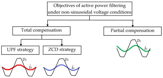
Figure 4.
Objectives of active power filtering under non-sinusoidal voltage conditions.
- Unity power factor (UPF):
In the case of the UPF strategy, the supply current after compensation has the same waveform and zero crossing points as the voltage.
- Zero current distortion (ZCD):
In the case of the ZCD strategy, the supply current after compensation is sinusoidal regardless of voltage distortion, and it is in phase with the fundamental component of the voltage, leading to unity displacement power factor. The total power factor is less than unity, being affected by the voltage distortion.
In the case of undistorted supply voltage, partial compensation can be implemented in the following two forms:
- Reactive power compensation: when the reactive component of the fundamental load current is compensated, the supply current is distorted, but its fundamental is in phase with the voltage. Unity displacement power factor is obtained.
- Compensation of current harmonics only.
In this case, the following two ways of implementation can be achieved:
- Filtering of all harmonics: when a sinusoidal supply current is obtained but out of phase with respect to the voltage.
- Selective filtering of certain harmonics: when the resulting supply current is no longer sinusoidal and its zero crossings are out of phase with respect to the voltage.
4. Reference Current Generation
In SAPF schemes with current control, the correct operation of the filtering system is determined by the accurate tracking of the prescribed current by the actual current to be controlled.
As shown in Figure 5, to compensate for the load current drawn by the nonlinear load, the SAPF inverter should inject a proper compensating current (iF) in the point of common coupling (PCC). For this, there is the possibility of direct control of the inverter output current or indirect control of this current through the supply current upstream of the PCC (is). Thus, depending on the type of control adopted, direct or indirect, one of the two currents constitutes the input of the current control block.
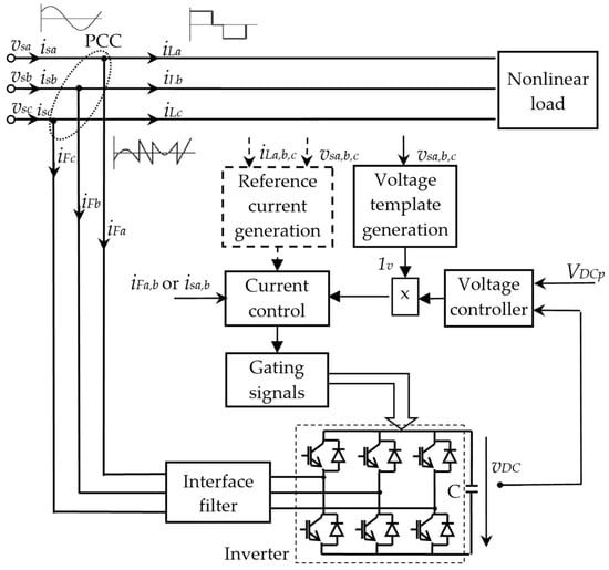
Figure 5.
General scheme of a two-level SAPF system.
The generation of the reference current is specific to the type of current control. Regardless of this, the reference current has an active component that ensures the coverage of power losses, whose amplitude is provided by the DC-voltage controller (that maintains the DC-voltage at the prescribed value VDCp), and its waveform is a sinusoid of unity magnitude in phase with the supply voltage, provided by the voltage template generation block.
4.1. Reference Current Generation for the Direct Control
In the case of direct control (Figure 6), the total reference current (iFtp), which is prescribed to be obtained on the inverter AC-side, is the sum of the component iFp (generated according to the compensation objective and a chosen calculation method based on measured load currents and supply voltages) and component iFup (the active current required to cover the power losses and maintain the DC voltage at its prescribed value) [108].

Figure 6.
Structure of the control system in the case of direct current control.
Generally, the methods of reference current generation can be classified into three large categories, namely time-domain, frequency-domain, and soft-computing techniques (Figure 7) [2,31,32,33]. They have led to a wide variety of implementation methods, aiming to obtain the best possible performance of the active filtering system.
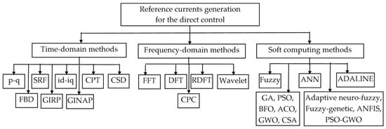
Figure 7.
Reference current generation methods for direct current control.
4.1.1. Time-Domain Methods
Time-domain methods are the simplest approaches, as they offer increased speed and fewer calculations as compared to their counterpart categories.
The p-q method, also called the instantaneous power method (active and reactive powers), is based on the expression of the current to be compensated (iF) in terms of an instantaneous active power (p) and an instantaneous reactive power (q), expressed in turn in terms of the components of the voltage vectors (vα and vβ) and load currents (iLα and iLβ) in the stationary orthogonal coordinate system (α-β). The components of p and q to be compensated (pF and qF) are extracted, and, according to them, the currents to be compensated in the stationary reference frame (α-β) are calculated, which are then transformed into the three-phase system (a, b, and c) (Figure 8). It is one of the methods with the most implementations in the SAPF control since the 1980s, when the first form of the p-q theory was proposed [147]. There are many implementations for three-phase, three-wire systems operating under sinusoidal voltage conditions, corresponding to the original theory [7,8,20,32,39,73,101,102,148,149,150,151,152,153,154]. Extended applicability of the method was also considered for operation under nonsinusoidal voltage conditions [108,146,155,156,157,158] and multilevel SAPFs [58,111]. In [159], a novel harmonic extraction method named “virtual input signal-based instantaneous power theory” is introduced to improve the performance under unbalanced conditions.
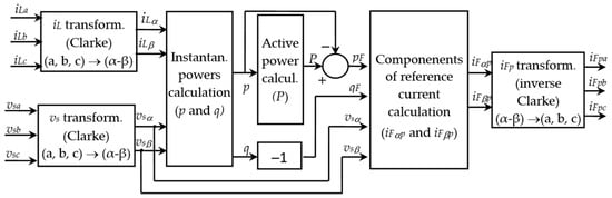
Figure 8.
Calculation of reference currents by the p-q method for total compensation.
The synchronous reference frame (SRF)-based algorithm is based on the transformation of the currents from the three-phase system into a two-phase (d-q) rotating system synchronized with the voltage vector, whose rotation speed is determined by the fundamental frequency. The use of a PLL (phase-locked loop) circuit is needed for the calculation of the angle θ required in the coordinate frame transformation. In the rotating system (d-q), the fundamental component of the current becomes a continuous quantity, which can be obtained by using a low-pass filter (LPF). In this way, the fundamental of the distorted current and the total harmonic current to be compensated can be easily identified (Figure 9). An alternative is the direct extraction of the current to be compensated through a high-pass filter (HPF) [41,154]. The SRF-based method is frequently adopted to generate the reference current due to the small computation required and low complexity in implementation [41,46,146,154,160]. However, when the supply voltages are imbalanced and/or distorted, the design of the PLL circuit is more difficult. The use of SRF-based PLL in a SAPF has been widely reported [20,49,161,162,163]. Enhanced PLLs have been proposed as alternatives to the conventional SRF-PLL to accurately predict the phase or frequency by using specific filtering techniques to determine the fundamental frequency positive sequence. A multiple reference frame-based PLL (MRF-PLL) is presented in [162]. The use of a novel feedback integral PLL-based modified SRF for a unified power quality conditioner for power quality enhancement in a power distribution network is proposed in [163]. Reference [49] proposes a reconfiguration of the modified SRF-PLL structure to extract positive sequence signals by using a negative feedback loop in the LPF and a nonlinear adaptive filter in the phase detector unit, being able to track changes in amplitude, phase angle, and frequency of the input signal.

Figure 9.
Calculation of reference currents by the SRF method.
The id-iq method proposed by V. Soares in 1997 [164] is a simplified variant of the SRF method. According to it, the use of the synchronization PLL circuit is avoided by calculating the load current components (iLd and iLq) in the rotating coordinate frame aligned with the voltage vector. The angle required for the transformation is calculated only according to the components of the voltage vector in the stationary reference frame (α-β) and its modulus. Then, the active component of the fundamental harmonic is the DC component ILd of the current iLd and is obtained with an LPF. The components of the current desired to be drawn from the power supply after compensation in the rotating (d-q) reference frame are required to be ILd and zero. Finally, the transition of the currents to the three-phase system follows (Figure 10). There are several implementations of the id-iq methods [165,166,167,168,169].

Figure 10.
Calculation of reference currents by the id-iq method.
The Conservative Power Theory (CPT)-based method uses the theory proposed by Paolo Tenti in 2003 [170]. It uses quantities such as voltages, currents, their integrals, and derivatives to define average and instantaneous powers, which are conservative quantities in electrical systems. According to the CPT theory, the load-distorted current can be decomposed into an active component, a reactive component, and a void component, which in turn has an active scattering component, a reactive scattering component, and a generated component. The active and reactive components can be expressed in terms of the equivalent conductance and susceptance per phase [146,170,171]. For total compensation of harmonics, reactive power, and unbalances, only the calculation of the active component based on active power and equivalent conductance is required, and the reference current to be compensated is simply obtained by subtracting the active component from the total load current (Figure 11). The implementation of the CPT method in the SAPF control was successfully achieved for the compensation of harmonics and reactive power in three-phase, three-wire active filtering systems [151,153,172,173] and under unbalanced supply voltage conditions [174]. A selective compensation of the various components of unwanted currents is treated in [175,176]. The initial formulation of the CPT was later revised to cope with variable frequency systems. As the application of the CPT for the compensation of harmonic distortions and unbalances in such systems involves an appropriate measurement of the CPT’s basic electrical quantities, the authors of [177] are focused on CPT measurements and moving averages and propose an efficient way of computing moving averages and turn it into an adaptive one.
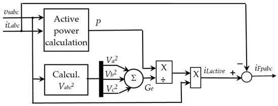
Figure 11.
Calculation of reference currents by the CPT-based method for total compensation.
The method of current synchronous detection (CSD) arose to be used in situations where there is asymmetry in the three-phase supply voltage system. It first provides the expressions of the currents absorbed from the power supply after compensation as a function of the total active power, the total rms voltage, the phase rms voltages, and the instantaneous voltages of each phase. Then, the reference currents on each phase are expressed as the difference between the load currents and the currents absorbed from the network after compensation [146,178]. The authors of [179] suggest an algorithm for three-phase SAPF, which is an expanded version of classical CSD. It involves the detection of active or fundamental reactive currents in each phase symmetrically and equally, based on the decomposition of the fundamental reactive component and the harmonics under unbalanced power conditions. In the recent reference [180], a CSD method combined with a positive sequence detector was proposed to control the current in a balanced and sinusoidal waveform even under unbalanced and distorted power supply conditions.
The Fryze–Buchholz–Depenbrock (FBD) method is based on the theory of the same name proposed in 1992, when the active current on each phase (ika) was defined as a function of an equivalent conductance (G), expressed as a collective active power (PΣ) and a collective effective voltage value (║vΣ║) [181]. The non-active currents to be compensated for on each phase are then expressed as the difference between the active currents and the load-distorted currents. Thus, the method only allows the total compensation of all inactive currents [146,153,157,182,183]. The simple algorithm is highlighted in Figure 12. As the excessive delay of the LPFs affects the SAPF dynamic response, the use of a generalized moving average filter having characteristics of short delay and flexible construction according to the characteristics of load current is proposed in [184]. A modified algorithm when the supply voltage is distorted is based on the estimation of the current reference that guarantees an optimal power exchange [185]. The impact on the FBD method when power supply voltage drops asymmetrically is analyzed in [186], and an improved reactive power and harmonic current detecting method based on voltage sequence decomposition is introduced.

Figure 12.
Calculation of reference currents by FBD-based method.
The method based on the generalized instantaneous reactive power (GIRP) theory was proposed by Peng and Lai in 1996 [187] and is based on the decomposition of the distorted load current vector into the instantaneous active component (iLp) and the instantaneous reactive component (iLq), expressed as a function of the instantaneous active power of the load (pL) and the vector of instantaneous reactive power (qL = vs × iL). Thus, to compensate both the harmonics and the reactive power of the load, the reference current imposed at the SAPF output has the following two components [146,187,188] (Figure 13):
where pL~ is the oscillatory component of the instantaneous active power of the load. There are different implementations of this method in the literature [146,187]. There are also implementations of applying FBD theory in the control of SAPF even under nonideal voltage conditions and unbalanced load [188,189,190,191].
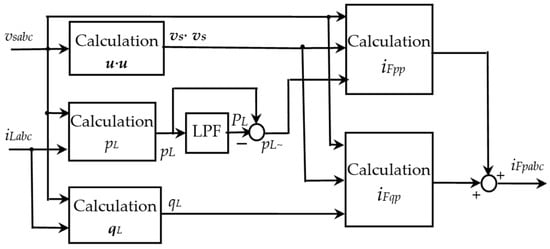
Figure 13.
Calculation of reference currents by GIRP-based method.
The method of generalized instantaneous non-active power (GINAP) was introduced by F.Z. Peng and L.M. Tolbert in 2000 by defining the active (ip) and inactive (iq) components of the current as a function of a reference voltage up(t), which depends on the compensation objective. Thus, the reference voltage determines the waveforms of the currents absorbed from the power supply after compensation and can be either the supply voltage if a unity power factor is desired or the fundamental of the supply voltage if a sinusoidal current is desired after compensation [146,192,193]. In the expression of the active component of the current, the active power P(t) and the rms value of the reference voltage Up(t) are used, which are calculated over a previous time interval Tc. There is research on the influence of this time interval, depending on the compensation objective [146,193,194]. Implementations based on GINAP theory in the control of a three-phase SAPF show outstanding results [150,183,191,195,196,197,198,199,200], including dynamic response [201]. Critical analysis of the compensation results using the p-q, FBD, and GINAP methods showed that the GINAP method leads to very good performance even under conditions of a non-sinusoidal supply voltage and non-periodic load currents [194,202].
In recent research [203], a new time-domain method for the reference current extraction without using an LPF/HPF in its implementation is proposed. It is called the matrix pencil method (MPM) and is based on the assumption that the non-linear load current can be expressed as a linear combination of sinusoidal signals and, consequently, the pure sine wave of the fundamental component can be synthesized. This method achieves high accuracy and fast response time.
Another new time-domain method named transformation algorithm (TTA), to be used in high-power medium voltage SAPF with a three-level NPC VSI inverter, is introduced in [23]. It can detect positive/negative sequences of the fundamental current, active and reactive components of the fundamental current, and selected-order harmonics. The needed synchronizing signal with the power supply voltage is obtained using a dedicated user software phase lock loop (SPLL) based on a d-q transformation, which provides fast and accurate response and better performance in abnormal grid conditions.
The novel Savitzky–Golay Filter (SGF) for the reference current generation, along with the use of an SGF-based PLL proposed in 2023 [204], greatly improves the performance of a conventional SAPF under grid disturbances. SGF is a weighted moving average finite impulse response (FIR) filter with accurate data smoothing capabilities that not only removes noise and harmonics from signals but also keeps the basic information of the signals unaltered [204].
The alternative approach, named modular fundamental element detection (modular-FED), to perform extraction of harmonic currents and subsequently utilize that data to generate reference currents is introduced in [205]. It exhibits modular structure and operates without additional service from PLL, and it is found to be significantly outperforming the standard SRF technique, especially when the supply grid is unbalanced and/or distorted regardless of any nonlinear loads connected.
An insightful summary of the most recognized time-domain-based instantaneous power theories with comprehensive mathematical-conceptual and application frameworks for professionals is given in [206].
There are also methods for the direct extraction of the harmonics in the time domain, which are selective harmonic extraction methods. They are flexible because the reference current to be compensated contains only the harmonics of interest. There are various techniques in this regard, including the least mean square (LMS) technique, the Second-Order Generalized Integrator (SOGI) technique, the Adaptive Notch Filter (ANF) technique, and the Kalman filter technique [100,207,208,209,210]. Most of them have some drawbacks, such as computational burden, the need to consider a compromise between steady state error and dynamic performance, and poor flexibility of harmonic extraction [100,211].
4.1.2. Frequency-Domain Methods
The algorithms for the reference current generation in the frequency domain are mainly based on Fourier analysis of the distorted load currents, which involves either fast Fourier transform (FFT) [20,21,106,212,213,214] or, more frequently, discrete Fourier transform (DFT) [20,100,145,211,215,216,217].
Starting from the traditional DFT controller with only one feedback path, an enhanced DFT-based controller is proposed in [215], which provides feedback path and gain coefficient for each harmonic.
To improve the overall control performances of dynamic response, structure flexibility, and control robustness, a DFT-based controller for selective harmonic compensation is proposed in [216], which maintains the advantage of excellent selectivity but also realizes the individual control parameters tuning for each harmonic frequency.
A fast repetitive control (FRC) scheme designed in the synchronous rotational frame together with a close loop harmonic detection scheme are proposed in [217] to improve the dynamic response of the SAPF and the compensation performance. In the closed-loop harmonic detection module, a sliding DFT (SDFT) algorithm performs an N-point DFT, and the magnitude and phase for each selected harmonic current are extracted.
Three improved recursive discrete Fourier transform (RDFT)-based methods are introduced in [211] to suppress wideband harmonics in electric aircraft or high-speed train power grids. First, RDFT is regarded as a series of DFT and inverse DFT (IFT). Then, by rearranging the sampling frequency of DFT according to the extracted harmonic, the computational burden is reduced. Further, the comb filter is reconfigured based on the load current spectrum.
Another frequency-domain method for the reference current generation is the discrete wavelet transform (DWT), which has a flexible time-frequency resolution through a nonuniform division of frequency domain [211]. As a general principle, to use the wavelets, the load current is first decomposed in a number of frequency bands using DWT or the wavelet packet transform (WPT), depending on the frequency resolution required. Then, to separate the fundamental component and higher-order harmonics and reconstruct them in the time domain, the inverse discrete wavelet transform (IDWT) or the inverse wavelet packet transform (IWPT) are used [218].
In [218], the use of the undecimated wavelet packet transform (UWPT) acting as a filter bank for harmonic component extraction, followed by the Inverse undecimated wavelet packet transform (IUWPT), is proposed for enhanced estimation of the reference compensating current in SAPFs, both in stationary and nonstationary regimes. The UWPT leads to both time invariance and uniform frequency bandwidth decomposition.
A harmonic detection method based on lifting wavelet transform (LWT) as a method to build second-generation wavelets has been proposed in [219] to improve the performance of APF.
In different applications, wavelets have been used as low-pass filters to extract only the fundamental component in order to obtain the reference compensating current after the subtraction of the fundamental from the load current [218,220]. A wavelet-window-based low-pass filter leading to fast transient response and desirable accuracy is proposed in [220,221] to be used in the traditional synchronous reference d-q frame algorithm for reference current generation. To extract the DC components of the instantaneous active and reactive powers specific to the p-q power theory, a wavelet-based low-pass filter (WB-LPF) is used in [222,223]. It provides very good performance under low harmonic orders and improves both steady state and dynamic response.
In the recently published paper [224], a wavelet fuzzy neural network controller combined with a supertwisting sliding mode controller is developed to control the harmonics through a SAPF. A wavelet layer is added to the structure of the fuzzy neural network to further improve the feature extraction ability.
The Currents’ Physical Components (CPC) method in the frequency domain is based on the theory of the physical components of the current, proposed by Professor Leszek S. Czarnecki in the 1980s–1990s [225,226] and further developed to be used for compensation objectives [227,228]. This allows the interpretation of the physical phenomenon of powers. According to the CPC theory, the distorted current related to an unbalanced three-phase load has the following four orthogonal components: active (ia—related to the transmission of active power); reactive (ir—related to the reciprocating flow of energy); unbalanced (iu related to the load imbalance); and the load-generated component (ig—related to load nonlinearity or its parameters’ time-variance). The first three components of the current are included in the fundamental harmonic and can be expressed in terms of the equivalent admittance (Ye1 = Ge1 + jBe1) and the unbalanced admittance (A1) [225,226,227,228]. Figure 14 illustrates the principle of calculating the reference current by the CPC method under sinusoidal voltage conditions [146,229]. The CPC method has been successfully used to calculate the reference current in three-phase SAPFs [229,230,231,232,233,234,235].

Figure 14.
Calculation of reference currents by the CPC-based method.
The main drawback of frequency-domain approaches is the long time required to collect enough samples to be processed in the Fourier analysis. In addition, the use of a high-performance control processor is needed [20].
4.1.3. Soft-Computing Methods
The soft-computing-based methods offer robust and low-cost solutions for situations characterized by imprecision and uncertainty, and they are either learning techniques or techniques inspired by natural phenomena. This category includes complex techniques such as fuzzy logic control algorithm, artificial neural network (ANN), adaptive linear neurons (ADALINE), genetic algorithm (GA), particle swarm optimization (PSO), bacterial foraging optimization (BFO), ant colony optimization (ACO), grey wolf optimizer (GWO), and cuckoo search algorithm (CSA) [2,8,20,32,34,35,36,37,38,39,40,41,42,43]. There are also possible combinations of these methods, like the adaptive neuro-fuzzy control algorithm, fuzzy-genetic algorithm, adaptive neuro-fuzzy inference system (ANFIS), and hybrid particle swarm optimization-grey wolf optimization (PSO-GWO) [8,31,32].
4.2. Reference Current Generation for the Indirect Control
In the case of indirect control, the reference current is the current that is desired to be drawn from the power supply after compensation. Most simply, this is the active component of the load current, the amplitude of which is the output of the DC-voltage controller (Figure 15). Due to its simplicity, this method of generating the reference current has been frequently adopted in the control of active power filters [20,48,110,236,237,238,239].
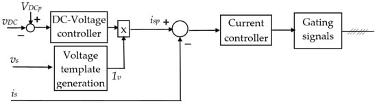
Figure 15.
Structure of the control system in the case of indirect current control, performed only based on the output of the DC-voltage controller.
Another method of implementing indirect control involves generating the reference supply current as a sum of two components, i.e., a reference component resulting from the measured load current and the supply voltage (according to a generation strategy related to the direct control) and an active component necessary to cover power losses and maintain constant the DC voltage (Figure 16). This method involves, compared to the previous one, the measurement of the load current to generate the main component of the reference supply current. There are also implementations of this reference current generation method [45,46,49,107,240,241,242].

Figure 16.
Structure of the control system in the case of indirect current control using a reference component resulting from the measured load current and the supply voltage.
5. Current Control Techniques
There are various techniques for the current control in SAPFs’ systems (Table 2).
Table 2.
Main strengths and weaknesses of the most used SAPFs’ current control techniques.
The technique of current control through hysteresis controllers is one of the most used due to its simple implementation, good stability, accurate current tracking, rapid response in the transient regime, and robustness to the variation of the load parameters [2,39,44,45,46,47,48,49,50,65,102,104,106,108,109,121,127,128,152,160,240]. According to the hysteresis control technique, the error is centered in a predetermined hysteresis band, and when the error exceeds the hysteresis limits, the appropriate switching decision is made to control the error within the hysteresis band so that the reference current is followed faithfully (Figure 17).

Figure 17.
Fixed band current hysteresis control loop structure.
However, current control using a fixed hysteresis band results in a variable switching frequency, leading to increased switching losses. In addition, the variable switching frequency complicates the design of the coupling filter and the selection of the DC-voltage value, affecting the efficiency and reliability of the active power filter. In practical applications, however, the maximum switching frequency can be limited by adopting a suitable hysteresis band and a suitable sampling step [108,146].
To avoid variable switching frequency operation, adaptive hysteresis current control methods, namely variable hysteresis band, have been proposed. The idea of using an adaptive hysteresis band control belongs to B.K. Bose, who proposed such a variant in 1990 for an AC electric car driving system [243]. It was later adapted for active power filtering systems as well [44,45,46,47,48,49,50]. Most often, the hysteresis band is adapted according to the DC voltage, coupling inductance, switching/modulation frequency, rms supply voltage, and prescribed current variation slope (Figure 18). In a simplified proposal, the derivative of the prescribed current no longer intervenes, leading to an increase in the speed of the current controller [244]. To improve the performance of SAPF without exact information about its parameters, the adaptive hysteresis band can be calculated using fuzzy logic represented by a set of defined membership functions, as proposed in a recently published paper [49]. A new space vector hysteresis control strategy that combines hysteresis and space vector control is proposed in the recent paper [245] for harmonic current tracking.

Figure 18.
Adaptive band current hysteresis control loop structure in case of indirect current control.
In recent years, with the advances in the computational power of modern microprocessors, model predictive control (MPC) has been implemented in the control of static power converters to predict the future behavior of controlled currents based on the system model and using past and present inputs and outputs [2,19,20,25,34,51,52,101]. The predictions are evaluated based on an imposed cost function, and the sequence that minimizes the cost function is chosen. This modern control technique allows to minimize the switching frequency in high-power inverters and to achieve an accurate current control, but precise knowledge of the filter model and a lot of calculations are required [34]. As the implementation of a model-based predictive current controller is by nature parameter dependent, a robust high-bandwidth discrete-time predictive current control technique with low computational demand is presented and used in [246,247] by including an adaptive internal model for the estimated uncertainty dynamics within the current feedback structure.
Other advanced methods have been proposed, including deadbeat control (DBC) [2,34,53,54,55,56,248], sliding mode control (SMC) [2,34,57,58,59,60,61,249], proportional-resonant (PR) control [54,56,62,63,64,65,66,67], repetitive control [2,18,25,26,27,62,68,69,70,71,72], multi-loop control [73,74,75,76,77,78], multiresonant control [79,80,81,82,83], or fuzzy-logic-based control techniques [84,85,86,87].
A performance comparison of some advanced, improved current prediction-based deadbeat control methods used in SAPFs is carried out in the recent paper [56].
Concerning the sliding mode control, which involves the motion of state variables under the user-defined sliding surface, most of the current contributions refer to the use of single-phase SAPFs. For the three-phase, three-wire systems, to improve the phase and magnitude of the inverter output impedance at the desired frequency and finally the reliability of the whole system, a PCC feedforward voltage reconstruction method using Kalman filter estimation is proposed in [60]. In [249], a novel discrete-time robust adaptive super-twisting sliding mode controller based on the robust model reference adaptive control theory is presented.
A comprehensive and up-to-date presentation of the use of PR controllers, which can be designed to operate at specific frequencies, in the current control of SAPFs was recently made in [66]. A fuzzy logic algorithm is proposed as the adaptive gain mechanism for the PR controller.
In [26], a PI controller is combined with a half-cycle repetitive controller to combine the fast response characteristics of the PI controller with the non-static tracking characteristics of the repetitive controller. For a better harmonic suppression ability when the frequency varies, an improved frequency-adaptive virtual variable sampling-based repetitive control with an infinite impulse response LPF is introduced in [68].
For an LCL-coupled inverter, a hybrid multi-loop current control that integrates the one-step predictive current control into the conventional multi-loop current control to compensate for the calculation delay effect and prevent the high-frequency noise is discussed in [75]. In [74], a harmonic current controller and a fundamental current controller are in parallel to constitute dual loops of digitally controlled LCL-type SAPFs, with no extra sensors or no extra active damping loop. A delay–compensation control link is proposed to replace the proportional part of the PR fundamental current controller and widen the damping region, contributing to the improvement of the system’s robustness. An estimation algorithm with a minimum number of sensors in a three-loop control structure without neglecting the capacitor dynamics is proposed in [76]. This approach leads to a good stability margin, better transient performance, and good steady-state accuracy.
Multiresonant controllers are used to obtain sinusoidal power supply currents, regardless of the degree of distortion of the supply voltages. Several flawed approaches related to some tuning methods reported in the topical literature for the multiresonant control systems used in grid-connected converters, such as SAPFs, are discussed in [82]. Then, a practical, robust controller tuning method based on the disk margin stability analysis and a global search algorithm is proposed. In [83], the proposed multiresonant current controller is composed of a proportional controller and multiple resonant controllers tuned at different orders of harmonics. The adopted design method is based on the error transfer function and allows obtaining a more appropriate phase compensation angle and a wider stable region of the controller gain, so that a smaller frequency sensitivity and a faster response speed are achieved.
An adaptive backstepping fuzzy neural network control of SAPF using a fuzzy sliding scheme is presented in [250] to improve the filtering performance. It involves considering the SAPF system as consisting of a series of subsystems and uses the virtual control to simplify the controller design. An adaptive fuzzy system adjusts the sliding gain to compensate for the approximation error of the neural network and diminish the chattering.
Table 2 summarizes the main strengths and weaknesses of the most used current control techniques for SAPFs.
6. Modulation Strategies
To generate the gating signals for the inverter’s power semiconductor devices, the main strategies include the basic carrier-based sine-triangle PWM, also called sinusoidal PWM (SPWM), and the newer Space Vector Pulse Width Modulation (SVPWM) technique with its various implementations.
6.1. Sinusoidal PWM
In the standard modulation technique SPWM, a low-frequency sinusoidal reference signal is compared with a high-frequency triangular carrier signal, and the comparator output defines the operating range of switching control signals. In practice, the reference signal is achieved by a current controller, usually of PI type, from the current error signal. It must be taken into account that the variation of DC voltage has the effect of reference signal amplitude distortion and leads to “on–off” spectral errors.
The amplitude distortion of the PWM waveforms limits the fundamental component amplitude, and unexpected low-order harmonics are introduced [34,251]. The basic SPWM method is enhanced in [251] by using Bessel filtering functions to eliminate side band harmonics of the carrier signal.
6.2. Space Vector PWM
The Space Vector Pulse Width Modulation (SVPWM) aims to find the appropriate switching combinations and their duty ratios according to certain modulation schemes. SVPWM operates in a complex space plane divided into six sectors. The variable output voltage of the power inverter is obtained from eight possible switching combinations (six active vectors placed 60° apart and two zero state vectors in the hexagon center) (Figure 19). The reference vector is used to locate two adjacent active vectors in an identified sector and compute the time for which each one is active. The time interval in a sampling period for zero state vectors is computed too [2,34,41,252]. Due to its benefits, such as fixed-frequency operation, low current harmonics, better use of the DC voltage (for the same DC voltage, the maximum output voltage is 15% greater with SVPWM than that with SPWM [34,97,98]), good reliability, being very simple to implement in a digital system, and strong antijamming of the digital control technique, SVPWM has become the preferred option in three-phase SAPFs [2,252]. However, there are drawbacks determined by the need for a considerable amount of time to carry out the calculations, leading to delays in the control process and restrictions on the maximum sampling time, maximum switching frequency, and maximum bandwidth [2,34,252]. In addition, the SVPWM performance is not satisfactory in the over-modulation regions [34].
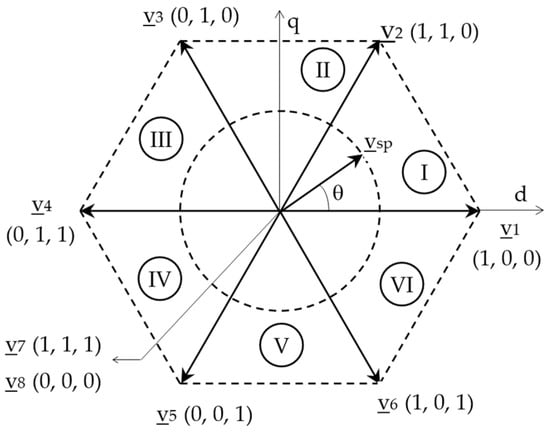
Figure 19.
The eight voltage vectors and the prescribed reference vector specific to SVPWM.
To overcome these problems, advanced control methods are used. A sliding mode controller based on the SVPWM strategy is proposed in [253] to improve the dynamic response speed, eliminate chattering, and improve the robustness of the controller.
In [41], an optimized switching technique using a neural network for SVPWM is used, which has lesser computation time and computes the gating pulses effectively in the over-modulation regions, so that improved harmonic reduction is obtained for all modulation regions.
The use of a SAPF using an ANN approach for both generations of the reference compensating current and current control is proposed in [254]. The current controller is ANN-based SVPWM, and superior filtering characteristics and better dynamic response are illustrated.
The results presented in [255] prove that by using SVPWM-based dual SAPF, the performance is improved in terms of lower harmonic distortion and switching loss, along with better power factor and DC-voltage utilization.
7. DC-Voltage Control
For the proper operation of VSI-based SAPFs, the DC voltage across the compensation capacitor must be kept constant to compensate for the power losses. The DC-capacitor voltage must be maintained at a level that is high enough so that the SAPF is able to precisely inject the desired current into the PCC. The main reason for the DC-voltage variation is the change in the pollutant load, which creates an active power exchange with the power supply [99]. The voltage regulation process is said to have been accomplished when the real power drawn by the SAPF is made equal to its switching losses [20].
The most common solution for the DC-voltage control in SAPF systems, with very good results, is the simple use of a correctly tuned PI controller [48,54,55,57,66,69,95,100,101,102,103,104,105,106,107,108]. However, the PI controller also has drawbacks, such as sensitivity to unbalance and parameter variations and complexity of linear mathematical modeling for the controller design [31]. Due to the use of fixed values of proportional gain and integral gain, the PI technique is unable to work satisfactorily under dynamic-state conditions, leading to high overshoot and large time delay [20].
The use of a fuzzy controller is a frequently chosen alternative for DC-voltage regulation [49,87,110,256]. The use of stages of fuzzification and defuzzification and some databases and rules are specific to this type of control (Figure 20). The fuzzy logic controller approach is known for its performance, durability, and ability to maintain a stable DC voltage under extreme perturbations [49].
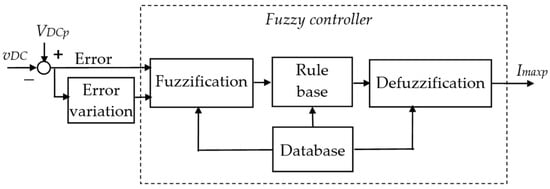
Figure 20.
Block diagram of a fuzzy controller for the DC voltage.
A new idea of using a fuzzy PI controller is presented in [109]. It acts as a high-precision PI controller when the error between the prescribed DC voltage and real DC voltage is less than the imposed threshold and as a fast-response fuzzy PI controller when the error is greater than the threshold.
For the DC-voltage control in a three-phase, three-wire injection hybrid active power filter used in the medium and high voltage distribution network, a fuzzy linear active disturbance rejection with anti-disturbance capabilities is proposed in [257]. It consists of a fuzzy proportional controller, a linear extended state observer (LESO), and a total disturbance compensation link.
Recently, the authors of [39] proposed an online-trained PI using the PSO approach for the control of DC voltage in SAPF.
A new technique proposed for the control of both DC voltage and compensation current in a three-level SAPF is the synergetic control [111]. For DC-voltage control, the active power is considered the output quantity and the DC-voltage across the capacitor as the command quantity. Synergetic control is a robust nonlinear control technique considered easy to implement, as the system response can be adjusted easily due to the presence of a small number of coefficients. Also, it is proven that the new proposed controller based on the partial order synergistic controller is superior to the conventional control in terms of DC voltage tracking and current harmonic distortion reduction for a three-level inverter-based SAPF [258].
A simple sliding mode DC-voltage controller, which has only one gain in its design, is shown to be simpler to design than the conventional PI controller and leads to improved dynamic performance of SAPF and good stability of the DC-voltage [114]. To make use of the main advantages of the sliding mode control, such as fastness, robustness, and stability under large load variations, the performance of a sliding mode DC-voltage controller and of a PI controller were compared in [99], showing superior performance of the sliding mode controller in terms of transient response, overshoot, and settling time. The superiority of sliding mode control in both steady-state and dynamic conditions is illustrated also in [113].
To effectively reduce the system chattering in both the reaching phase and the sliding phase and to achieve reachability and asymptotic stability of the three-phase SAPF system, a novel bi-sliding mode PI control of the DC voltage is proposed in [112].
The idea to change the common PI controller for the DC-voltage control by an artificial neural network controller, with two hidden layers with seven neurons logsig and tansig activation functions and one output layer having a linear activation function, is presented in [42] to improve the SAPF performance.
Two novel methods to design the DC-voltage controller taking into account the physical meaning of the SAPF control scheme are proposed in [115]. They are based on the capacitor energetic model. In the first approach, the converter loss power is directly modulated from the energy error through the PI controller. The other approach involves the determination of the loss power from the multiplication of the measured DC voltage across the capacitor and the current reference deduced from a voltage PI controller.
8. Direct Power Control
To improve the SAPFs performance, a newer alternative considered is that of direct control of the active and reactive powers, named direct power control (DPC), rather than control of the current. Thus, the control algorithm uses, as control variables, instantaneous active and reactive powers analogous to the torque and flux control of an induction motor specific to direct torque control (DTC).
The DPC method was proposed by Noguchi and his co-authors in 1998 [259]. Since then, there have been implementations first in the PWM rectifiers control and then for SAPFs [8,55,57,88,89,90,91,92,93,94,95].
According to the DPC principle, the instantaneous active and reactive powers are calculated by any known method; the prescribed active power is the product of the output of the DC-voltage controller and the measured DC voltage, and the prescribed reactive power is zero to achieve full compensation. Control of active and reactive powers is achieved by hysteresis controllers. Their outputs, together with the information related to the sector in which the supply voltage phasor is located, are inputs to a block that contains a predefined switching table and will determine the switching sequences of the power semiconductor devices (Figure 21).
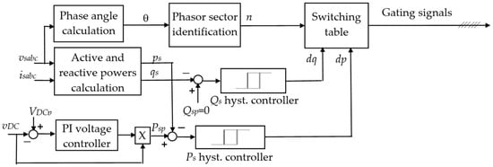
Figure 21.
Block diagram of the direct power control.
Using a predefined switching table has advantages, such as simplifying the control, eliminating internal current control loops, and PWM modulators, resulting in a more efficient and faster implementation of the control technique.
In designing the switching table (Table 3), 12 sectors are considered in the stationary reference frame (α-β), where the voltage phasor can be located, depending on the angle θ (Figure 22).
Table 3.
Switching table for DPC [259].
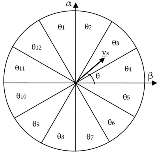
Figure 22.
Twelve sectors in the stationary reference frame for voltage phasor location.
To improve the active filtering performance, the switching table can be redefined, and the hysteresis band of the power controllers can be dynamically adjusted. Thus, compared to the switching table initially proposed by Noguchi [259], other switching tables were later proposed to reduce the reactive power fluctuations and the response time of the control system [260].
In [55], a deadbeat-based DPC method is adopted for SAPF to have the merits of both deadbeat and DPC techniques. Thus, the simplicity and superior performance of the DPC are accompanied by highly digitally compatible, high dynamic response, and robustness against model parameters and load variations specific to deadbeat control. In addition, an offline delay compensation method is proposed to improve the sampling delay issue associated with the deadbeat control.
Two methods based on the DPC control implementation according to the measured electrical quantities are presented in [88]. To generate the reference active and reactive powers, the direct method uses the basic principle of DPC, whereas the indirect method is based on their estimation by measuring the load currents and the voltages at the PCC, followed by extraction of load current harmonics using a multivariable filter. It is concluded that, although indirect DPC requires more current sensors, multivariable filters, and more instructions for implementation, it leads to lower harmonic distortion and low DC-voltage overshoot.
The comparison between DPC and predictive DPC made in [89] shows that better current distortion and less power ripple are obtained by predictive DPC strategy. Also, the same comparison carried out in [90] concludes that the average switching frequency is better than in the case of DPC.
The authors of [91] have developed a switching loss reduction technique, even under conditions of varying input power factor, for the predictive DPC by using offset signal injection. In the control algorithm, future converter input voltages are used, which are modified by injecting a future offset voltage. The switching operation of one of the three converter phases exposed to the highest input current can be stopped to reduce the switching losses, and an independent control of the active and reactive power is performed.
An improved predictive direct power control for three-phase SAPF using two metaheuristic methods, namely Grey Wolf Optimizer and Ant Lion Optimizer algorithms, is presented in [92] to reduce the maximum overshoot and undershoot of the DC-voltage variation. Thus, the Ant Lion Optimizer algorithm shows better improvement than Grey Wolf Optimizer and the conventional method (reducing high overshoot at start-up, avoiding the peak of active power, minimizing power ripples, and improving harmonic distortion).
In the fuzzy-predictive direct power control implementation of a grid-connected photovoltaic system associated with a SAPF, it is proven that the predictive power control ensures a flexible settlement of active power amounts exchanged with the power supply under a unity power operation [93].
Derived from the measurement of converter currents and estimating the virtual flux at the PCC, the power control of SAPF is based on virtual flux DPC in [94]. The results of real-time implementation prove that the proposed control strategy offers a great performance solution for distributed generation applications.
The association of DPC with space vector modulation in the control of SAPF is proposed in [57] to decrease the high active and reactive power ripples while maintaining a fixed switching frequency. Specifically, a voltage modulator is used instead of the predefined switching table, and two supertwisting second-order sliding mode controllers in the rotating reference frame are added instead of hysteresis controllers. This technique provides high robustness and dynamics for external perturbations. The same combination of DPC and space vector modulation is proposed in [95] by using an H∞ controller for the closed loop active and reactive power in order to ensure a fast response, perfect reference tracking with required dynamic behavior, and low power ripple level.
9. Renewable Energy Sources Integration with SAPF
In recent years, the use of renewable energy integrated systems, such as photovoltaic (PV), wind, and fuel cell systems, has spread widely, especially due to advancements in technology and motivating government policies. The power quality disturbances produced by renewable energy integration are worthy of consideration, and thus the topic of renewable energy source integration with SAPF became very attractive. A comprehensive review of SAPF control techniques, maximum power point tracking (MPPT), and renewable energy sources (RESs) integrated with SAPF is provided in [32].
9.1. PV Integrated SAPF
Figure 23 illustrates the block diagram of a common PV-based SAPF system [32].
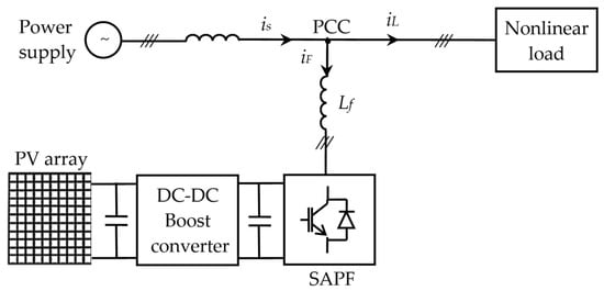
Figure 23.
Block diagram of a common PV-based SAPF.
During sunlight, PV-based SAPF provides power to the grid and improves power quality, whereas during no-sunlight periods, it only provides reactive power compensation and filters out harmonic currents [32].
A significant improvement in maximum power tracking and harmonics detection for PV-based SAPF systems is presented in the recent paper [38]. Thus, a new hybrid Support Vector Machine (SVM) Regression Perturb and Observe algorithm is proposed for an efficient MPPT strategy, and a novel SVM regression–ADALINE PQ strategy is designed to upgrade harmonics detection.
In [117], a SAPF that can control both the MPPT and the power factor of a nonlinear load connected to the power supply with new sliding mode controllers is presented. Three sliding mode controllers are used to control the DC voltage and the d and q current components of the active filter using the p-q theory.
In the grid-interfaced solar system presented in [120], which operates as a SAPF, direct power control is adopted to inject the generated solar energy into the electrical network and to compensate for the reactive power and load current harmonics. An advanced technique of tracking the maximum power point based on fuzzy logic has also been developed to take care of the rapidly changing weather conditions.
Contrary to the common two-stage PV system (Figure 23), which is composed of the DC-DC boost converter and voltage source inverter, the use of a Z-source inverter (ZSI) having a few numbers of power switches and providing the buck and boost functionalities in only one-stage operation is proposed in [8]. Solar-powered SAPF with the use of ZSI is adopted to improve the power quality.
9.2. Wind Energy Integrated SAPF
In the integration of wind energy with power networks, the power quality problems can be addressed by using SAPFs (Figure 24). The wide range control of power output due to varying wind can be achieved by a doubly fed induction generator for large variable-speed wind turbines and a permanent magnet synchronous generator. SAPF improves stability, minimizes voltage sag problems, enhances power quality, and increases power factor under fluctuating wind speeds [32].
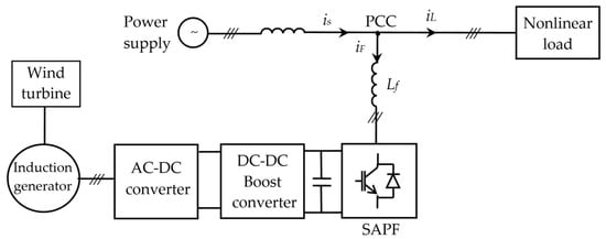
Figure 24.
Block diagram of a wind energy-based SAPF.
A review and application of SAPF with grid-connected wind turbine generators for mitigating load harmonics have been carried out in [261]. For the reference current generation, the synchronous reference frame technique has been adopted, and a hysteresis band current controller provides the gating signals for power semiconductor devices. The effect of wind turbines at PCC under fixed and varying natures of wind speed is also investigated. An advanced variable frequency-based wind turbine system operates in the islanding mode to cancel the harmonics [262,263].
9.3. Fuel-Cell-Integrated SAPF
Power generation through fuel cell technology, which uses hydrogen and oxygen to convert chemical energy into electrical energy, is pollution-free and is more and more used as a backup power source in commercial, industrial, and residential buildings [32].
The integration of fuel cells into the built environment has several benefits to the user, but the behavior of these systems can produce an undesirable impact on the grid distribution system at the point of connection. The block diagram of a fuel cell-based SAPF is illustrated in Figure 25 [32]. In [264], a load-following SAPF is proposed to mitigate the grid impact and improve overall local power quality.
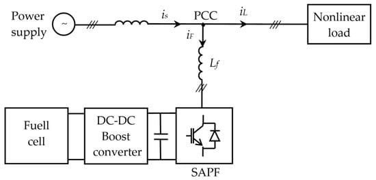
Figure 25.
Block diagram of a fuel-cell-based SAPF.
9.4. Hybrid Renewable Energy Sources Integration with SAPF
Hybrid RESs, which consist of two or more RESs used to increase the output power, fulfill the customer demand, and provide an uninterruptible power supply, ensure improvement of voltage regulation, active power control, and fault ride-through capability [32].
In the grid integration of hybrid RESs, power quality is an important issue. Figure 26 shows the general structure of hybrid RES integrated SAPF [32].
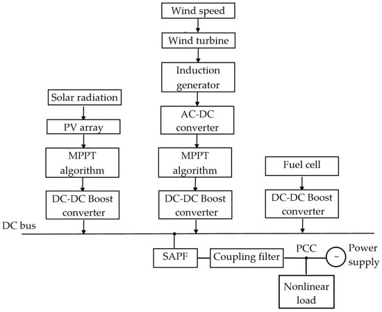
Figure 26.
General structure of the hybrid RES-integrated SAPF.
PV and wind energy-based sources are the most widely used RESs, and they are somewhat complementary. Their combination improves the system reliability. In [265], the power quality analysis of a grid-tied hybrid solar-wind energy system based on a three-level inverter is presented, and the reduction of the total harmonic distortion is highlighted.
A hybrid system consisting of a photovoltaic panel, wind turbine, fuel cell, electrolyzer, super capacitor, power converter, and a three-phase load is presented in [266]. The load supply is based on the PV panel and wind turbine, while the fuel cells are backup to compensate for a possible power load shortage. The storage of the surplus of produced power is achieved through a hydrogen tank by an electrolyzer system. Active and reactive power control is performed.
The authors of [267] introduced a grid-connected hybrid power system integrating a photovoltaic array, a fuel cell stack, and a battery as input power sources in a unified structure by means of a new three-input DC-DC boost converter, which supplies a grid-connected inverter. The proposed system also has SAPF capabilities, being able to compensate both reactive and current harmonics.
10. Optimizing the Sizing and Placement of SAPF
The large-scale use of SAPFs to improve the power quality involves costs, which cannot be neglected. Therefore, scientists around the world are conducting research aimed at developing techniques to minimize the investment costs through the optimal sizing and placement of these devices. As a result of optimization, the levels of current and voltage distortions required by the existing norms and the reduction of power losses due to the harmonic distortion are reached at a lower cost.
A comprehensive topical review paper, i.e., [4], presents different approaches to the optimization of placement and sizing of active power filters in supply networks in terms of the objective functions and the optimization algorithms. The optimization algorithms are classified in conventional non-heuristic (combinatorial, mixed integer programming, continuous), metaheuristic (evolutionary, fuzzy, human-based, swarm-based), and heuristic. Besides the most common goal function defined as the sum of current RMS values of all APFs installed in the network, other goal functions and optimization constraints leading to financial cost minimization are reviewed. The authors point out that the particle swarm optimization-based algorithms were used in by far the largest group of the latest articles.
A subsequent approach to a review paper, i.e., [43], is directed towards a novel approach for simultaneously optimizing the allocation of active power filters and capacitors to improve the harmonic content, network losses, and voltage profile of distribution networks. Then, a modified particle swarm optimization algorithm is presented as the optimization tool, and three case studies were conducted on the IEEE 18-bus test system.
In the equally recent paper [268], the optimal placement and sizing of active power filters in a radial distribution system for harmonic reduction is discussed. A recently developed technique called nonlinear load position-based current injection is used for the placement of APFs achievement, and a teaching-learning-based optimization algorithm is proposed for the optimal size of APFs. The results indicate that the teaching-learning-based optimization algorithm outperforms the other algorithms in computational performance.
11. Trends and Future Developments
The further research on the topic of SAPF will certainly be related to the development of power electronic and microprocessor technology, high-performance control algorithms, advanced digital technology for control implementation, as well as to the use of artificial intelligence to optimize the active power filter placement.
To improve the efficiency of the active filtering systems, the current IGBTs that have become practically standard in the SAPF structure could be replaced on a large scale with high-performance transistors, such as GaN or SiC, or perhaps new types of high-performance power semiconductor devices. Through significantly higher switching frequencies, much lower switching losses, and low conduction losses, the compensation efficiency can be much higher, and the size of the entire system becomes much smaller.
Development of advanced multilevel converters, including their control, can give better efficiency, high frequency noise reduction, and a lower burden in terms of power semiconductor devices. Minimizing the number of power semiconductor devices in the active power filter topology is one of the main research trends.
Although there are many publications on the use of multi-level inverters in SAPFs and new topologies continue to emerge, in practice only three-level ones are used in most situations. The use of multi-level active power filters in the medium and high voltage distribution network must be promoted more in the future.
A new advancement in hybrid topologies of active filtering systems could reduce the capacity and the cost of the DC-side capacitor, improve its voltage level, and improve the performance of the whole system.
The development of advanced control algorithms for SAPFs has a good development perspective to ensure the very faithful tracking of the prescribed quantities and the control in different scenarios to eliminate harmonics. To improve the accuracy of harmonic and reactive current detection influenced by the variation of the power supply frequency and the specific delay of the low-pass filters, advanced adaptive algorithms are expected to be introduced in the future. Discussions and studies can also be about finding the balance between better filtering performance, greater efficiency, and cost reduction.
Through a modular and scalable design, SAPFs could be more versatile to handle different nonlinear loads, enabling adaptation to system requirements and efficient compensation in various operating scenarios.
Saving energy expenses and enhancing the stability of the power grid can be achieved by the large-scale use of energy storage integration with SAPFs in modern utility systems.
The development of suitable integration of SAPFs in renewable energy-based microgrid systems to improve the microgrids performance is another actual concern of power engineers leading to high-performance control solutions [269].
To improve power quality and reduce the total costs, further research related to the optimization of the sizing and placement of active power filters may concern the efficiency of optimization processes in the case of large and extensive low-voltage networks. Another research direction could be the optimization by using global control of a group of SAPFs. In the area of solving the problem of APF placement, a new trend can also be found related to the dynamic growth of machine learning [4].
It is very likely that, in the coming years, many publications will be published on this topic, which will provide many interesting and innovative solutions.
12. Conclusions
Improving the power quality by SAPFs is a topical issue, both in terms of the development of innovative power circuit configurations and in terms of advanced control solutions to solve all the aspects that define it. In this context, this paper presents an extensive topical review of using SAPFs in three-phase, three-wire systems.
The main power circuit configurations were presented, first related to the standard two-level topology with voltage source inverter and voltage source inverter and associated interface filters. A comparison between VSI-based SAPFs and CSI-based SAPFs was provided. The topology of a three-phase SAPF with two parallel interleaved inverters sharing the same DC capacitor to reduce the size of the coupling inductors and the DC capacitor switching stress was also presented.
Among the multilevel inverters often used in SAPFs in order to improve the AC current waveform and to reduce the switching losses and voltage stress of power semiconductor devices, the most practically implemented three-level topologies (NPC, FC, and CHB) are discussed, and some comparisons are expressed.
The opportunities and the current state resulting from the emergence of new power semiconductor devices with new capabilities (higher switching frequency, lower switching losses, and better temperature tolerance), such as SiC and GaN, were also highlighted based on references from recent years.
After presenting the possible objectives of active power filtering, the reference current generation techniques occupy an important place in this paper. In the case of direct current control, the main methods included in the categories of time domain, frequency domain, and the newest soft techniques are detailed, including their implementations. The reference current generation techniques specific to the indirect current control were presented based on two identified structures of the control system, first using only the output of the DC-voltage controller and the second using a reference component resulting from the measured load current and the supply voltage.
As the performance of the active filtering system is determined by the accurate tracking of the reference current by the actual current to be controlled, various techniques for the current control in SAPFs’ systems were reviewed and synthesized, and their main strengths and weaknesses were highlighted. Furthermore, the modulation strategies to generate the gating signals for the inverter’s power semiconductor devices were discussed, starting with the classic sinusoidal PWM and continuing with space vector PWM.
Then, the existing approaches in the literature for the DC-voltage control, which ensure the proper operation of SAPF, were presented synthetically. The PI control, fuzzy control, improved fuzzy PI control, online trained PI using the PSO approach, sliding mode control, bi-sliding mode PI control, artificial neural network control, and the new synergetic control are some of the control methods referred to in this review paper.
The newer alternative of direct control of the active and reactive powers instead of current control was also discussed in this review paper. The method was presented as a basic principle, and then the latest developments regarding the use of DPC in the control of SAPFs, such as deadbeat-based DPC, predictive DPC, switching loss reduction technique, Grey Wolf Optimizer and Ant Lion Optimizer algorithms, fuzzy-predictive DPC, and combinations of DPC and space vector modulation, were reviewed.
Concerning the integration of renewable energy sources with SAPFs, a comprehensive review of PV, wind energy, fuel cell, and hybrid renewable energy source integration was presented in this paper. In the PV integrated SAPF, new results and approaches to improve the maximum power tracking and harmonics detection were highlighted. For example, to obtain an efficient MPPT strategy, a new hybrid Support Vector Machine (SVM) Regression Perturb and Observe algorithm was proposed, and, in order to upgrade harmonic detection, a novel SVM regression–ADALINE PQ strategy was designed [38]. Solar-powered SAPF with the use of a Z-source inverter was also adopted to improve the power quality [8]. In wind energy integrated SAPF, the use of SAPF leads to the improvement of power quality and increased power factor under fluctuating wind speeds. Regarding the integration of fuel cells into the built environment, besides the positive effects, a load-following SAPF is presented as a solution for the mitigation of undesirable impacts on the grid distribution system at PCC and overall power quality improvement [264]. To improve the power system’s reliability, the use of hybrid renewable energy sources integrated with SAPF was discussed, and recent achievements were presented.
The most recent achievements regarding techniques to minimize the investment costs through the optimal sizing and placement of SAPFs were also synthesized in terms of the objective functions and new optimization algorithms. The particle swarm optimization algorithm was identified as the optimization tool used most frequently in recent articles.
The identification of trends and future developments in the SAPF topic provides a complete picture of the prospects for using this equipment to improve the power quality in electrical systems.
This paper is expected to be useful for researchers and practitioners working on improving power quality in three-phase, three-wire systems through SAPFs.
Author Contributions
Conceptualization, M.P. and A.B.; methodology, M.P., A.B. and C.V.S.; investigation, M.P., A.B., C.V.S., M.L. and L.A.; resources, M.P., A.B., C.V.S., M.L., and L.A.; writing—review and editing, M.P. and A.B.; supervision, M.P. and A.B. All the authors actively participated in the conception and writing of this paper. All authors have read and agreed to the published version of the manuscript.
Funding
This research received no external funding.
Data Availability Statement
Not applicable.
Conflicts of Interest
The authors declare no conflicts of interest.
Abbreviations
| ACO | Ant Colony Optimization |
| ADALINE | Adaptive Linear Neurons |
| ANF | Adaptive Notch Filter |
| ANFIS | Adaptive Neuro Fuzzy Inference System |
| ANN | Artificial Neural Network |
| ANPC | Active Neutral Point Clamped |
| APF | Active Power Filter |
| BFO | Bacterial Foraging Optimization |
| CHB | Cascaded H-Bridge |
| CPC | Currents’ Physical Components |
| CPT | Conservative Power Theory |
| CSA | Cuckoo Search Algorithm |
| CSD | Current Synchronous Detection |
| CSI | Current Source Inverter |
| DC | Direct Current |
| DFT | Discrete Fourier Transform |
| DPC | Direct Power Control |
| DTC | Direct Torque Control |
| DWT | Discrete Wavelet Transform |
| EV | Electric Vehicle |
| FBD | Fryze–Buchholz–Depenbrock |
| FC | Flying Capacitor |
| FED | Fundamental Element Detection |
| FFT | Fast Fourier Transform |
| FIR | Finite Impulse Response |
| FRC | Fast Repetitive Control |
| GA | Genetic Algorithm |
| GaN | Gallium Nitride |
| GINAP | Generalized Instantaneous Non-Active Power |
| GIRP | Generalized Instantaneous Reactive Power |
| GTO | Gate Turn-Off Thyristor |
| GWO | Grey Wolf Optimizer |
| HPF | High-Pass Filter |
| IDWT | Inverse Discrete Wavelet Transform |
| IGBT | Insulated-Gate Bipolar Transistor |
| IFT | Inverse Discrete Fourier Transform |
| IUWPT | Inverse Undecimated Wavelet Packet Transform |
| IWPT | Inverse Wavelet Packet Transform |
| LESO | Linear Extended State Observer |
| LMS | Least Mean Square |
| LPF | Low-Pass Filter |
| LWT | Lifting Wavelet Transform |
| MOSFET | Metal Oxide Semiconductor Field-Effect Transistor |
| MPC | Model Predictive Control |
| MPM | Matrix Pencil Method |
| MPPT | Maximum Power Point Tracking |
| MRF-PLL | Multiple Reference Frame-Based PLL |
| NPC | Neutral-Point Diode Clamped |
| PCC | Point of Common Coupling |
| PI | Proportional-Integral |
| PLL | Phase-Locked Loop |
| PR | Proportional-Resonant |
| PSO | Particle Swarm Optimization |
| PSO-GWO | Particle Swarm Optimization-Grey Wolf Optimization |
| PV | Photovoltaic |
| PWM | Pulse Width Modulation |
| RB–IGBT | Reverse Blocking-Insulated Gate Bipolar Transistor |
| RDFT | Recursive Discrete Fourier Transform |
| RES | Renewable Energy Source |
| SAPF | Shunt Active Power Filter |
| SDFT | Sliding Discrete Fourier Transform |
| SGF | Savitzky–Golay Filter |
| SiC | Silicon Carbide |
| SMC | Sliding Mode Control |
| SOGI | Second Order Generalized Integrator |
| SPLL | Software Phase Lock Loop |
| SPWM | Sinusoidal Pulse Width Modulation |
| SRF | Synchronous Reference Frame |
| SVM | Support Vector Machine |
| SVPWM | Space Vector Pulse Width Modulation |
| TTA | Transformation Algorithm |
| UPF | Unity Power Factor |
| UWPT | Undecimated Wavelet Packet Transform |
| VSI | Voltage Source Inverter |
| WB-LPF | Wavelet-Based Low Pass Filter |
| ZCD | Zero Current Distortion |
| ZSI | Z-Source Inverter |
References
- Maciążek, M. Active power filters and power quality. Energies 2022, 15, 8483. [Google Scholar] [CrossRef]
- Das, S.R.; Ray, P.K.; Sahoo, A.K.; Ramasubbareddy, S.; Babu, T.S.; Kumar, N.M.; Elavarasan, R.M.; Mihet-Popa, L. A comprehensive survey on different control strategies and applications of active power filters for power quality improvement. Energies 2021, 14, 4589. [Google Scholar] [CrossRef]
- Li, D.; Wang, T.; Pan, W.; Ding, X.; Gong, J. A comprehensive review of improving power quality using active power filters. Electr. Power Syst. Res. 2021, 199, 107389. [Google Scholar] [CrossRef]
- Buła, D.; Grabowski, D.; Maciążek, M. A review on optimization of active power filter placement and sizing methods. Energies 2022, 15, 1175. [Google Scholar] [CrossRef]
- Afonso, J.L.; Tanta, M.; Pinto, J.G.O.; Monteiro, L.F.C.; Machado, L.; Sousa, T.J.C.; Monteiro, V. A review on power electronics technologies for power quality improvement. Energies 2021, 14, 8585. [Google Scholar] [CrossRef]
- Duc, M.L.; Hlavaty, L.; Bilik, P.; Martinek, R. Harmonic mitigation using meta-heuristic optimization for shunt adaptive power filters: A review. Energies 2023, 16, 3998. [Google Scholar] [CrossRef]
- Dehury, D.; Mishra, R.N.; Panda, R. Power quality enhancement by shunt active power filter employing different control strategies: A concise review. In Proceedings of the 1st International Conference on Circuits, Power and Intelligent Systems (CCPIS), Bhubaneswar, India, 1–3 September 2023; pp. 1–6. [Google Scholar] [CrossRef]
- Smaida, E.; Saulo, M.J.; Abdellah, K.; Nyakoe, G.; Ahuna, M. Solar-powered shunt active power filter using an advanced inverter topology ZSI: A Review. In Proceedings of the 2023 IEEE Africon, Nairobi, Kenya, 20–22 September 2023; pp. 1–6. [Google Scholar] [CrossRef]
- IEEE Standard 519-2014; IEEE 519 Recommended Practice and Requirements for Harmonic Control in Electric Power Systems. IEEE: New York, NY, USA, 2014.
- IEC Standard 61000-4-7; General Guide on Harmonics and Interharmonics Measurements, for Power Supply Systems and Equipment Connected Thereto. International Electrotechnical Commission (IEC): Geneva, Switzerland, 2010.
- IEC Standard 61000-4-30; Testing and Measurement Techniques-Power Quality Measurement Methods. International Electrotechnical Commission (IEC): Geneva, Switzerland, 2015.
- Luo, A.; Shuai, Z.; Zhu, W.; Shen, Z.J.; Tu, C. Design and application of a hybrid active power filter with injection circuit. IET Power Electron. 2010, 3, 54–64. [Google Scholar] [CrossRef]
- Shuai, Z.; Luo, A.; Shen, J.; Wang, X. Double closed-loop control method for injection-type hybrid active power filter. IEEE Trans. Power Electron. 2011, 26, 2393–2403. [Google Scholar] [CrossRef]
- Shuai, Z.; Luo, A.; Tu, C.; Liu, D. New control method of injection-type hybrid active power filter. IET Power Electron. 2011, 4, 1051–1057. [Google Scholar] [CrossRef]
- Asiminoaei, L.; Aeloiza, E.; Kim, J.H.; Enjeti, P.; Blaabjerg, F.; Moran, L.T.; Sul, S.K. Parallel interleaved inverters for reactive power and harmonic compensation. In Proceedings of the 2006 37th IEEE Power Electronics Specialists Conference, Jeju, Republic of Korea, 18–22 June 2006; pp. 1–7. [Google Scholar] [CrossRef]
- Asiminoaei, L.; Aeloiza, E.; Kim, J.H.; Enjeti, P.; Blaabjerg, F.; Moran, L.T.; Sul, S.K. An interleaved active power filter with reduced size of passive components. In Proceedings of the Twenty-First Annual IEEE Applied Power Electronics Conference and Exposition, Dallas, TX, USA, 19–23 March 2006. [Google Scholar] [CrossRef]
- Asiminoaei, L.; Aeloiza, E.; Enjeti, P.N.; Blaabjerg, F. Shunt active-power-filter topology based on parallel interleaved inverters. IEEE Trans. Ind. Electron. 2008, 55, 1175–1189. [Google Scholar] [CrossRef]
- Lin, H.; Wang, X.; Chen, D.; Guo, X.; Chen, G. A control method for the interleaved active power filter with SiC-MOSFETs. Energy Rep. 2022, 8, 400–407. [Google Scholar] [CrossRef]
- Souza, L.L.; Rocha, N.; Fernandes, D.A.; Sousa, R.P.R.; Jacobina, C.B. Grid harmonic current correction based on parallel three-phase shunt active power filter. IEEE Trans. Power Electron. 2022, 37, 1422–1434. [Google Scholar] [CrossRef]
- Hoon, Y.; Mohd Radzi, M.A.; Hassan, M.K.; Mailah, N.F. Control Algorithms of Shunt Active Power Filter for Harmonics Mitigation: A Review. Energies 2017, 10, 2038. [Google Scholar] [CrossRef]
- Vodyakho, O.; Mi, C.C. Three-level inverter-based shunt active power filter in three-phase three-wire and four-wire systems. IEEE Trans. Power Electron. 2009, 24, 1350–1363. [Google Scholar] [CrossRef]
- Mehrasa, M.; Pouresmaeil, E.; Akorede, M.F.; Jørgensen, B.N.; Catalão, J.P.S. Multilevel converter control approach of active power filter for harmonics elimination in electric grids. Energy 2015, 84, 722–731. [Google Scholar] [CrossRef]
- Kashif, M.; Hossain, M.J.; Zhuo, F.; Gautam, S. Design and implementation of a three-level active power filter for harmonic and reactive power compensation. Electr. Power Syst. Res. 2018, 165, 144–156. [Google Scholar] [CrossRef]
- Ranjan, A.; Bhaskar, D.V. Grid Resilience enhancement through TPTL NPC inverter-based shunt active power filters with dual fundamental component extraction. In Proceedings of the 2023 IEEE 2nd Industrial Electronics Society Annual On-Line Conference (ONCON), Online, 8–10 December 2023; pp. 1–5. [Google Scholar] [CrossRef]
- Liu, Z.; Sha, M.; Zhu, R.; Hu, S. Designing a new control method for three-level active power filter. In Proceedings of the 2023 3rd International Conference on New Energy and Power Engineering (ICNEPE), Huzhou, China, 24–26 November 2023; pp. 311–314. [Google Scholar] [CrossRef]
- Guo, X.; Lin, H.; Chen, G. SiC-MOSFET shunt active power filter based on half-cycle SDFT and repetitive control. Energy Rep. 2021, 7, 246–252. [Google Scholar] [CrossRef]
- Lin, H.; Guo, X.; Chen, D.; Wu, S.; Chen, G. A frequency adaptive repetitive control for active power filter with 380V/75A SiC-inverter. IEEE Trans. Ind. Appl. 2022, 58, 5469–5479. [Google Scholar] [CrossRef]
- Ou, M.; Zou, J.; Liu, Q.; Yang, H. A dual-loop control strategy based on PI and repetitive control for APF with CoolSiC™ MOSFET. In Proceedings of the 2023 6th International Conference on Electrical Engineering and Green Energy (CEEGE), Grimstad, Norway, 6–9 June 2023; pp. 29–34. [Google Scholar] [CrossRef]
- Buyukdegirmenci, V.T.; Sozuer, A.; Milletsever, O.C.; Kozarva, O.F.; Oz, T.; Hava, A.M. Considerations for inverter topology selection and limitations in active power filtering applications. In Proceedings of the 2022 IEEE Power and Energy Conference at Illinois (PECI), Champaign, IL, USA, 10–11 March 2022; pp. 1–6. [Google Scholar] [CrossRef]
- Ma, C.-T.; Gu, Z.-H. Design and implementation of a GaN-based three-phase active power filter. Micromachines 2020, 11, 134. [Google Scholar] [CrossRef]
- Kumar, P.; Mahajan, A. soft computing techniques for the control of an active power filter. IEEE Trans. Power Deliver. 2009, 24, 452–461. [Google Scholar] [CrossRef]
- Kumar, R.; Bnsal, H.O. Shunt active power filter: Current status of control techniques and its integration to renewable energy sources. Sustain. Cities Soc. 2018, 42, 2210–6707. [Google Scholar] [CrossRef]
- Dubey, A.K.; Mishra, I.P.; Kumar, A. Comparative analysis of ROGI based shunt active power filter under current fed and voltage fed type non-linear loading condition. IFAC-Pap. 2022, 55, 156–161. [Google Scholar] [CrossRef]
- Tareen, W.U.K.; Aamir, M.; Mekhilef, S.; Nakaoka, M.; Seyedmahmoudian, M.; Horan, B.; Memon, M.A.; Baig, N.A. Mitigation of power quality issues due to high penetration of renewable energy sources in electric grid systems using three-phase APF/STATCOM Technologies: A Review. Energies 2018, 11, 1491. [Google Scholar] [CrossRef]
- Janpong, S.; Areerak, K.; Areerak, K. Harmonic Detection for Shunt Active Power Filter Using ADALINE Neural Network. Energies 2021, 14, 4351. [Google Scholar] [CrossRef]
- Sharma, S.; Verma, V. Modified control strategy for shunt active power filter with MRAS-based DC voltage estimation and load current sensor reduction. IEEE Trans. Ind. Appl. 2021, 57, 1652–1663. [Google Scholar] [CrossRef]
- Eslami, A.; Negnevitsky, M.; Franklin, E.; Lyden, S. An intelligent active power filter to mitigate harmonics and interharmonics. In Proceedings of the 2022 20th International Conference on Harmonics & Quality of Power (ICHQP), Naples, Italy, 29 May 2022–1 June 2022; pp. 1–6. [Google Scholar] [CrossRef]
- Jai, A.A.; Ouassaid, M. Machine learning-based ADALINE neural PQ strategy for a photovoltaic integrated shunt active power filter. IEEE Access 2023, 11, 56593–56618. [Google Scholar] [CrossRef]
- Madhusudhan Reddy, M.; Srinivasa Varma, P.; Lenine, D. Improving gain of real time PI controller using particle swarm optimization in active power filter. Microprocess. Microsyst. 2023, 97, 104760. [Google Scholar] [CrossRef]
- Tao, Z.; Wang, R.; Wang, S.; Zhang, Y. Harmonic detection of active power filter based on improved gray wolf algorithm with optimized VMD. In Proceedings of the 2023 3rd International Conference on Electrical Engineering and Mechatronics Technology (ICEEMT), Nanjing, China, 21–23 July 2023; pp. 47–50. [Google Scholar] [CrossRef]
- Subash Kumar, C.S.; Rajasekar, P.; Sathiyanathan, M.; Venkatesan, M. FPGA implementation of optimum switching angle control for shunt active filter using ANNSVPWM. Int. J. Electron. 2022, 109, 1532–1549. [Google Scholar] [CrossRef]
- Zakaria, L.; Amar, B. Neural network controller for three phase shunt active power filter using self tuning filter. In Proceedings of the 2022 19th International Multi-Conference on Systems, Signals & Devices (SSD), Sétif, Algeria, 6–10 May 2022; pp. 333–338. [Google Scholar] [CrossRef]
- Rezapour, H.; Fathnia, F.; Fiuzy, M.; Falaghi, H.; Lopes, A.M. Enhancing power quality and loss optimization in distorted distribution networks utilizing capacitors and active power filters: A simultaneous approach. Int. J. Electr. Power Energy Syst. 2024, 155, 109590. [Google Scholar] [CrossRef]
- Vahedi, H.; Sheikholeslami, A.; Bina, M.T.; Vahedi, M. Review and simulation of fixed and adaptive hysteresis current control considering switching losses and high-frequency harmonics. Adv. Power Electron. 2011, 2011, 397872. [Google Scholar] [CrossRef]
- Mahanty, R. Indirect current controlled shunt active power filter for power quality improvement. Int. J. Electr. Power Energy Syst. 2014, 62, 441–449. [Google Scholar] [CrossRef]
- Palpandian, A.R.; Chaoui, H. Power Quality improvement of the grid system with advanced hysteresis controller design. In Proceedings of the 2023 IEEE 14th International Conference on Power Electronics and Drive Systems (PEDS), Montreal, QC, Canada, 7–10 August 2023; pp. 1–6. [Google Scholar] [CrossRef]
- Guzman, R.; de Vicuña, L.G.; Morales, J.; Castilla, M.; Miret, J. Model-based control for a three-phase shunt active power filter. IEEE Trans. Ind. Electron. 2016, 63, 3998–4007. [Google Scholar] [CrossRef]
- Biswal, C.; Panigrahi, R.; Patjoshi, R. Experimental investigation of shunt active power filter for power quality enhancement. In Proceedings of the 2023 IEEE Renewable Energy and Sustainable E-Mobility Conference (RESEM), Bhopal, India, 17–18 May 2023; pp. 1–5. [Google Scholar] [CrossRef]
- Barik, P.K.; Shankar, G.; Sahoo, P.K.; Elavarasan, R.M.; Kumar, S.; Ibanez, F.M.; Houran, M.A.; Srivastava, A.K.; Terzija, V. A novel negative feedback phase locked loop-based reference current generation technique for shunt active power filter. Int. J. Electr. Power Energy Syst. 2023, 153, 109389. [Google Scholar] [CrossRef]
- Misra, B.; Tripathy, P.; Mohanty, R.; Sahoo, S.R.; Nayak, B. Performance analysis of an adaptive hysteresis band current controller based active power filter. In Proceedings of the 2022 Second International Conference on Advances in Electrical, Computing, Communication and Sustainable Technologies (ICAECT), Bhilai, India, 21–22 April 2022 ; pp. 1–5. [Google Scholar] [CrossRef]
- Pérez-Guzmán, R.E.; Rivera, M.; Wheeler, P.W. Recent advances of predictive control in power converters. In Proceedings of the 2020 IEEE International Conference on Industrial Technology (ICIT), Buenos Aires, Argentina, 26–28 February 2020; pp. 1100–1105. [Google Scholar] [CrossRef]
- Vazquez, S.; Rodriguez, J.; Rivera, M.; Franquelo, L.G.; Norambuena, M. Model predictive control for power converters and drives: Advances and trends. IEEE Trans. Ind. Electron. 2017, 64, 935–947. [Google Scholar] [CrossRef]
- Lin, J.; Yang, M. A new method of active power filter using dead beat control and repeated control. In Proceedings of the 2022 IEEE 5th International Electrical and Energy Conference (CIEEC), Nangjing, China, 27–29 2022; pp. 484–488. [Google Scholar] [CrossRef]
- Chen, J.; Shao, H.C.; Liu, C. An improved deadbeat control strategy based on repetitive prediction against grid frequency fluctuation for active power filter. IEEE Access 2021, 9, 24646–24657. [Google Scholar] [CrossRef]
- Pichan, M.; Seyyedhosseini, M.; Hafezi, H. A new deadbeat-based direct power control of shunt active power filter with digital implementation delay compensation. IEEE Access 2022, 10, 72866–72878. [Google Scholar] [CrossRef]
- Zhou, L.; Zhou, Z.; Qi, J.; Han, W. Hybrid prediction-based deadbeat control for a high-performance shunt active power filter. IEEE Access 2023, 11, 11118–11131. [Google Scholar] [CrossRef]
- Ouchen, S.; Benbouzid, M.; Blaabjerg, F.; Betka, A.; Steinhart, H. Direct power control of shunt active power filter using space vector modulation based on supertwisting sliding mode control. IEEE J. Emerg. Sel. Top. Power Electron. 2020, 9, 3243–3253. [Google Scholar] [CrossRef]
- Elallali, A.; Abouloifa, A.; Lachkar, I.; Taghzaoui, C.; Giri, F.; Mchaouar, Y. Nonlinear control of grid-connected PV systems using active power filter with three-phase three-level NPC inverter. IFAC-Pap. 2022, 55, 61–66. [Google Scholar] [CrossRef]
- Swetha, K.V.S. Comparative analysis and performance of DSTATCOM device using PI and second-order sliding mode control. Artif. Intell. Evol. Comput. Eng. Syst. 2020, 1056, 193–203. [Google Scholar] [CrossRef]
- Chen, B.; Wu, W.; Gao, C.; Orabi, M.; Koutroulis, E.; Chung, H.; Blaabjerg, F. A new stability enhancement method using KF estimation for the PWM-SMC-based grid-tied inverter under weak grid condition. IEEE J. Emerg. Sel. Top. Power Electron. 2022, 10, 6950–6959. [Google Scholar] [CrossRef]
- Ullah, I.; Ashraf, M. Sliding mode control for performance improvement of shunt active power filter. SN Appl. Sci. 2019, 1, 531. [Google Scholar] [CrossRef]
- Yang, S.; Wang, P.; Tang, Y.; Zhang, L. Explicit phase lead filter design in repetitive control for voltage harmonic mitigation of VSI-based islanded microgrids. IEEE Trans. Ind. Electron. 2017, 64, 817–826. [Google Scholar] [CrossRef]
- Khajehoddin, S.A.; Karimi-Ghartemani, M.; Jain, P.K.; Bakhshai, A. A resonant controller with high structural robustness for fixed-point digital implementations. IEEE Trans. Power Electron. 2012, 27, 3352–3362. [Google Scholar] [CrossRef]
- Gao, C.; He, S.; Cui, B.; Zhang, B.; Ming, L.; Leung, K.N.; Loh, P.C. Quantization effects on digital-PR-controlled active power filter. IEEE J. Emerg. Sel. Top. Power Electron. 2023, 11, 5785–5797. [Google Scholar] [CrossRef]
- Puhan, P.S.; Ray, P.K.; Pottapinjara, S. Performance analysis of shunt active filter for harmonic compensation under various non-linear loads. Int. J. Emerg. Electr. Power Syst. 2021, 22, 21–29. [Google Scholar] [CrossRef]
- Santiprapan, P.; Areerak, K.; Areerak, K. An adaptive gain of proportional-resonant controller for an active power filter. IEEE Trans. Power Electron. 2024, 39, 1433–1446. [Google Scholar] [CrossRef]
- Sou, W.K.; Chao, C.W.; Gong, C.; Lam, C.S.; Wong, C.K. Analysis, design, and implementation of multi-quasi-proportional-resonant controller for thyristor-controlled LC-coupling hybrid active power filter (TCLC-HAPF). IEEE Trans. Ind. Electron. 2022, 69, 29–40. [Google Scholar] [CrossRef]
- Liu, D.; Li, B.; Huang, S.; Liu, L.; Wang, H.; Huang, Y. An Improved Frequency-Adaptive Virtual Variable Sampling-Based Repetitive Control for an Active Power Filter. Energies 2022, 15, 7227. [Google Scholar] [CrossRef]
- Xu, H.; Peng, L.; Hu, K.; Chen, M. Vector repetitive control based on harmonic sequence extraction for shunt active power filters. In Proceedings of the 2022 IEEE 13th International Symposium on Power Electronics for Distributed Generation Systems (PEDG), Kiel, Germany, 26–29 June 2022; pp. 1–6. [Google Scholar] [CrossRef]
- Geng, H.; Zheng, Z.; Zou, T.; Chu, B.; Chandra, A. fast repetitive control with harmonic correction loops for shunt active power filter applied in weak grid. IEEE Trans. Ind. Appl. 2019, 55, 3198–3206. [Google Scholar] [CrossRef]
- Chen, Z.; Zha, H.; Peng, K.; Yang, J.; Yan, J. A design method of optimal PID-based repetitive control systems. IEEE Access 2020, 8, 139625–139633. [Google Scholar] [CrossRef]
- Pan, G.; Gong, F.; Jin, L.; Wu, H.; Chen, S. LCL APF based on fractional-order fast repetitive control strategy. J. Power Electron. 2021, 21, 1508–1519. [Google Scholar] [CrossRef]
- Azghandi, M.A.; Barakati, S.M.; Sahranavard, M.R. Multi-loop control of a current-source active power filter for harmonics mitigation in distribution systems. In Proceedings of the 2023 27th International Electrical Power Distribution Networks Conference (EPDC), Mashhad, Iran, Islamic Republic of Iran, 2–4 May 2023; pp. 186–190. [Google Scholar] [CrossRef]
- Yang, L.; Yang, J. A robust dual-loop current control method with a delay-compensation control link for LCL-type shunt active power filters. IEEE Trans. Ind. Electron. 2019, 34, 6183–6199. [Google Scholar] [CrossRef]
- Shen, Y.Y.; Tsai, M.J.; Zhou, J.; Cheng, P.-T. A hybrid multi-loop current control of the grid-connected converter with LCL filter. In Proceedings of the 2020 IEEE Energy Conversion Congress and Exposition (ECCE), Detroit, MI, USA, 11–15 October 2020; pp. 5409–5415. [Google Scholar] [CrossRef]
- Sivadas, D.; Vasudevan, K. Stability analysis of three-loop control for three-phase voltage source inverter interfaced to the grid based on state variable estimation. IEEE Trans. Ind. Appl. 2018, 54, 6508–6518. [Google Scholar] [CrossRef]
- Loh, P.C.; Holmes, D.G. Analysis of multiloop control strategies for LC/CL/LCL-filtered voltage-source and current-source inverters. IEEE Trans. Ind. Appl. 2005, 41, 644–654. [Google Scholar] [CrossRef]
- Sun, Z.; Wang, N.C. Novel multiple-loop composite control strategy for active power filter. In Proceedings of the 2010 Asia-Pacific Power and Energy Engineering Conference, Chengdu, China, 28–31 March 2010; pp. 1–6. [Google Scholar] [CrossRef]
- Mishra, M.K.; Lal, V.N. An advanced proportional multiresonant controller for enhanced harmonic compensation with power ripple mitigation of grid-integrated PV systems under distorted grid voltage conditions. IEEE Trans. Ind. Appl. 2021, 57, 5318–5331. [Google Scholar] [CrossRef]
- Hans, F.; Schumacher, W.; Chou, S.F.; Wang, X. Design of multifrequency proportional–resonant current controllers for voltage-source converters. IEEE Trans. Power Electron. 2020, 35, 13573–13589. [Google Scholar] [CrossRef]
- Xie, C.; Zhao, X.; Li, K.; Zou, J.; Guerrero, J.M. Multirate resonant controllers for grid-connected inverters with harmonic compensation function. IEEE Trans. Ind. Electron. 2019, 66, 8981–8991. [Google Scholar] [CrossRef]
- Ufnalski, B.; Michalczuk, M.; Galecki, A. Robust tuning of multiresonant current controllers for grid-tied converters and erroneous use of the Naslin polynomial method. IEEE Access 2022, 10, 88211–88225. [Google Scholar] [CrossRef]
- Xie, C.; Zhao, X.; Li, K.; Zou, J.; Guerrero, J.M. A new tuning method of multiresonant current controllers for grid-connected voltage source converters. IEEE J. Emerg. Sel. Topics Power Electron. 2019, 7, 458–466. [Google Scholar] [CrossRef]
- Saad, S.; Zellouma, L. Fuzzy logic controller for three-level shunt active filter compensating harmonics and reactive power. Electr. Power Syst. Res. 2009, 79, 1337–1341. [Google Scholar] [CrossRef]
- Malvezzi, V.B.; da Silva, S.A.O.; Campanhol, L.B.G.; Angélico, B.A. A comparative analysis between the PI and fuzzy controllers for current conditioning using a shunt active power filter. In Proceedings of the 2013 Brazilian Power Electronics Conference, Gramado, Brazil, 10 April 2013; pp. 981–986. [Google Scholar] [CrossRef]
- Amoozegar, D. DSTATCOM modelling for voltage stability with fuzzy logic PI current controller. Int. J. Electr. Power Energy Syst. 2016, 76, 129–135. [Google Scholar] [CrossRef]
- Salam, A.A.; Azran Ab Hadi, N. Fuzzy logic controller for shunt active power filter. In Proceedings of the 2014 4th International Conference on Engineering Technology and Technopreneuship (ICE2T), Kuala Lumpur, Malaysia, 27–29 August 2014; pp. 256–259. [Google Scholar] [CrossRef]
- Sayahi, K.; Faouzi, B. STATCOM/APF control using two proposed DPC strategies for power quality improvement. In Proceedings of the 2021 IEEE 2nd International Conference on Signal, Control and Communication (SCC), Tunis, Tunisia, 20–22 December 2021; pp. 270–275. [Google Scholar] [CrossRef]
- Ouchen, S.; Benlaloui, I.; Khamari, D.; Boutabba, T.; Benmessaoud, F.; Betka, A. Comparative study between DPC and PDPC controls applied on shunt active power filter. In Proceedings of the 2022 5th International Conference on Power Electronics and their Applications (ICPEA), Hail, Saudi Arabia, 29–31 March 2022; pp. 1–5. [Google Scholar] [CrossRef]
- da Cruz Ferreira, R.; De Morais Martins, P.H.; Rocha, N.; Da Silva, E.R.C.; Melo, V.F.M.B. Comparison between conventional and model predictive control for direct power control applied to a shunt active power filter. In Proceedings of the 2023 IEEE 8th Southern Power Electronics Conference and 17th Brazilian Power Electronics Conference (SPEC/COBEP), Florianopolis, Brazil, 26–29 November 2023; pp. 1–8. [Google Scholar] [CrossRef]
- Kim, J.C.; Park, J.C.; Kwak, S. Predictive direct power control technique for voltage source converter with high efficiency. IEEE Access 2018, 6, 23540–23550. [Google Scholar] [CrossRef]
- Bekakra, Y.; Zellouma, L.; Malik, O. Improved predictive direct power control of shunt active power filter using GWO and ALO –Simulation and experimental study. Ain Shams Eng. J. 2021, 12, 3859–3877. [Google Scholar] [CrossRef]
- Ouchen, S.; Betka, A.; Abdeddaim, S.; Menadi, A. Fuzzy-predictive direct power control implementation of a grid connected photovoltaic system, associated with an active power filter. Energy Convers. Manag. 2016, 122, 515–525. [Google Scholar] [CrossRef]
- Kamel, S.; Kadri, A.; Faouzi, B. Real-time implementation of a static compensator (STATCOM) / Active power filter for power quality improvement based on improved VF-DPC control strategy. In Proceedings of the 2022 8th International Conference on Control, Decision and Information Technologies (CoDIT), Istanbul, Turkey, 17–20 May 2022; pp. 1444–1449. [Google Scholar] [CrossRef]
- Ouchen, S.; Steinhart, H.; Benbouzid, M.; Blaabjerg, F. Robust DPC-SVM control strategy for shunt active power filter based on H∞ regulators. Int. J. Electr. Power Energy Syst. 2020, 117, 105699. [Google Scholar] [CrossRef]
- Belonkar, A.N.; Salodkar, M.R. Performance analysis of shunt active power filter with different switching signal generation techniques. Int. J. Sci. Res. 2015, 4, 331–336. [Google Scholar]
- Chelladurai, J.; Saravana Ilango, G.; Nagamani, C.; Senthil Kumar, S. Investigation of various PWM techniques for shunt active filter. Int. J. Elect. Eng. Elect. Syst. 2008, 1, 87–93. [Google Scholar]
- Rathnakumar, D.; LakshmanaPerumal, J.; Srinivasan, T. A new software implementation of space vector PWM. In Proceedings of the IEEE Southeastcon, Ft. Lauderdale, FL, USA, 8–10 April 2005; pp. 131–136. [Google Scholar]
- Benchouia, M.T.; Ghadbane, I.; Golea, A.; Srairi, K.; Benbouzid, M.H. Design and implementation of sliding mode and PI controllers based control for three phase shunt active power filter. Energy Procedia 2014, 50, 504–511. [Google Scholar] [CrossRef]
- Han, C.; Xinyan, Y.; Pengfei, J.; Bingyuan, Y.; Ke, D. Dynamic optimization for shunt active power filter to selectively extract harmonics with Vector Discrete Fourier Transform. In Proceedings of the 2023 IEEE 14th International Symposium on Power Electronics for Distributed Generation Systems (PEDG), Shanghai, China, 9–12 June 2023; pp. 971–977. [Google Scholar] [CrossRef]
- Majji, R.K.; Mishra, J.P.; Dongre, A.A. Extension p-q theory based MPCC strategy for shunt active power filter operation under dynamic loading scenario. In Proceedings of the 2022 IEEE Silchar Subsection Conference (SILCON), Silchar, India, 4–6 November 2022; pp. 1–6. [Google Scholar] [CrossRef]
- Mikkili, S.; Padamati, A. PHC, Id-Iq and p-q control strategies for mitigation of current harmonics in three-phase three-wire shunt active filter with PI controller. Int. J. Emerg. Electr. Power Syst. 2017, 18, 20160055. [Google Scholar] [CrossRef]
- Daramukkala, P.; Mohanty, K.B.; Karthik, M.; Swain, S.D.; Behera, B.P. Normalized sigmoid function LMS adaptive filter based shunt hybrid active power filter for power quality improvement. In Proceedings of the 2023 IEEE IAS Global Conference on Renewable Energy and Hydrogen Technologies (GlobConHT), Male, Maldives, 11–12 March 2023; pp. 1–6. [Google Scholar] [CrossRef]
- Lahiouel, Y.; Latreche, S.; Afghoul, H. Experimental realization using a dSPACE card of the PI control for an active power filter. In Proceedings of the 2022 19th International Multi-Conference on Systems, Signals & Devices (SSD), Sétif, Algeria, 6–10 May 2022; pp. 53–57. [Google Scholar] [CrossRef]
- Xiao, Z.; Xue, H.; Liu, T.; Zheng, G. Research on control strategy of shunt active power filter. In Proceedings of the 2023 8th Asia Conference on Power and Electrical Engineering (ACPEE), Tianjin, China, 14–16 April 2023; pp. 2377–2382. [Google Scholar] [CrossRef]
- El Korfolly, M.I.; Htita, I.; Elmasry, S.; Abdalla, O.H. Harmonic mitigation of variable speed drive with shunt active filter connected via LCL coupler. In Proceedings of the 2023 24th International Middle East Power System Conference (MEPCON), Mansoura, Egypt, 19–21 December 2023; pp. 1–7. [Google Scholar] [CrossRef]
- Shailly, D.; Chittora, P.; Singh, M. Comparative performance analysis of modern digital filters for power quality improvement using distributed static compensator (DSTATCOM). In Proceedings of the 2023 International Conference on Computer, Electronics & Electrical Engineering & their Applications (IC2E3), Srinagar Garhwal, India, 8–9 June 2023; pp. 1–7. [Google Scholar] [CrossRef]
- Popescu, M.; Bitoleanu, A.; Suru, V. A DSP-based implementation of the p-q theory in active power filtering under nonideal voltage conditions. IEEE Trans. Ind. Inf. 2013, 9, 880–889. [Google Scholar] [CrossRef]
- Liu, S.; Wang, Y.; Wu, Y.; Zhang, S.; Han, X. Research on DC voltage control of APF based on improved fuzzy PI control. In Proceedings of the 2022 IEEE International Conference on Mechatronics and Automation (ICMA), Guilin, China, 7–10 August 2022; pp. 174–179. [Google Scholar] [CrossRef]
- Suru, C.V.; Popescu, M.; Linca, M.; Stanculescu, A. Fuzzy logic controller implementation for the compensating capacitor voltage of an indirect current controlled active filter. In Proceedings of the 2020 International Conference and Exposition on Electrical and Power Engineering (EPE), Iasi, Romania, 22–23 October 2020; pp. 039–044. [Google Scholar] [CrossRef]
- Deffaf, B.; Farid, H.; Benbouhenni, H.; Medjmadj, S.; Debdouche, N. Synergetic control for three-level voltage source inverter-based shunt active power filter to improve power quality. Energy Rep. 2023, 10, 1013–1027. [Google Scholar] [CrossRef]
- Li, Z.; Ren, M.; Chen, Z.; Liu, G.; Feng, D. A bi-sliding mode PI control of DC-link voltage of three-phase three-wire shunt active power filter. IEEE J. Emerg. Sel. Topics Power Electron. 2022, 10, 7581–7588. [Google Scholar] [CrossRef]
- Deffaf, B.; Hamoudi, F.; Debdouche, N. Sliding mode control of a shunt active filter-comparative analysis with conventional PI control. In Proceedings of the 2022 19th International Multi-Conference on Systems, Signals & Devices (SSD), Sétif, Algeria, 6–10 May 2022; pp. 1422–1427. [Google Scholar] [CrossRef]
- Mousavi, M.S.; Jalilian, A.; Asadi, M. A sliding mode control method of dc-link capacitor voltage used in active power filter. In Proceedings of the 2015 30th International Power System Conference (PSC), Tehran, Iran, 23–25 November 2015; pp. 123–128. [Google Scholar] [CrossRef]
- Hoang, Q.-M.; Nguyễn, B.-H.; Vo-Duy, T.; Trovão, J.P.F.; Ta, M.C. Active power filter DC voltage control based on capacitor energetic model. In Proceedings of the 2022 11th International Conference on Control, Automation and Information Sciences (ICCAIS), Hanoi, Vietnam, 21–24 November 2022; pp. 529–534. [Google Scholar] [CrossRef]
- Azghandi, M.A.; Barakati, S.M.; Yazdani, A. Impedance-based stability analysis and design of a fractional-order active damper for grid-connected current-source inverters. IEEE Trans. Sustain. Energy 2021, 12, 599–611. [Google Scholar] [CrossRef]
- Cortajarena, J.A.; Barambones, O.; Alkorta, P.; Cortajarena, J. Sliding mode control of an active power filter with photovoltaic maximum power tracking. Int. J. Electr. Power Energy Syst. 2019, 10, 747–758. [Google Scholar] [CrossRef]
- Rayudu, K.; Muni, T.V.; Mustafa, M.; Subramaniam, G.; Kishore, K.V.; Babu Lella, V.M. Design of P-Q theory controller based solar PV system with shunt active filter to improve power quality. In Proceedings of the 2022 2nd International Conference on Intelligent Technologies (CONIT), Hubli, India, 24–26 June 2022; pp. 1–7. [Google Scholar] [CrossRef]
- Manohara, M.; Veera Reddy, V.C.; Vijaya Kumar, M. Power quality improvement of solar PV system with shunt active power filter using FS-MPC method. In Proceedings of the 2023 IEEE Renewable Energy and Sustainable E-Mobility Conference (RESEM), Bhopal, India, 17–18 May 2023; pp. 1–6. [Google Scholar] [CrossRef]
- Sarra, M.; Belkaid, A.; Colak, I.; Boudechiche, G.; Kayisli, K. Fuzzy-MPPT controller based solar shunt active power filter. In Proceedings of the 2022 11th International Conference on Renewable Energy Research and Application (ICRERA), Istanbul, Turkey, 18–21 September 2022; pp. 436–440. [Google Scholar] [CrossRef]
- Pani, S.; Samal, S.; Nayak, B.; Panda, B.; Mohapatra, A.; Barik, P.K. Fuzzy-HCC based shunt active power filter integrated hybrid energy system for compensation of harmonics. In Proceedings of the 2022 International Conference on Intelligent Controller and Computing for Smart Power (ICICCSP), Hyderabad, India, 21–23 July 2022; pp. 1–6. [Google Scholar] [CrossRef]
- Delincé, F.; Nguyen, T.; Ilves, K.; Okazaki, Y. Control of voltage source converters under varying grid impedance in active filter applications. In Proceedings of the 12th International Conference on Power Electronics, Machines and Drives (PEMD 2023), Brussels, Belgium, 23–24 October 2023; pp. 380–386. [Google Scholar] [CrossRef]
- Chaudhary, N.; Ranjan, A.; Bhaskar, D.V.; Panda, M.; Kumar, A.; Kumar, P. Harmonic reduction strategies for EV charging in power systems using shunt active power filter. In Proceedings of the 2023 3rd International Conference on Emerging Frontiers in Electrical and Electronic Technologies (ICEFEET), Patna, India, 21–22 December 2023; pp. 1–6. [Google Scholar] [CrossRef]
- Tsvetanov, D.; Djagarov, N.; Enchev, G.; Djagarova, J.; Blaabjerg, F. Harmonic compensation in ship power system using peak detection control strategy based shunt active power filter. In Proceedings of the 2023 IEEE International Conference on Environment and Electrical Engineering and 2023 IEEE Industrial and Commercial Power Systems Europe (EEEIC / I&CPS Europe), Madrid, Spain, 6–9 June 2023; pp. 1–8. [Google Scholar] [CrossRef]
- Tsvetanov, D.; Djagarov, N.; Grozdev, Z.; Djagarova, J. Harmonic compensation in ship power system using p-q theory control based shunt active power filter. In Proceedings of the 2022 8th International Conference on Energy Efficiency and Agricultural Engineering (EE&AE), Ruse, Bulgaria, 30 June 2022–2 July 2022; pp. 1–10. [Google Scholar] [CrossRef]
- Tsvetanov, D.; Djagarov, N.; Grozdev, Z.; Djagarova, J. Synchronous reference frame theory control for current harmonics suppression in ship power system using shunt active power filter. In Proceedings of the 2022 International Conference Automatics and Informatics (ICAI), Varna, Bulgaria, 6–8 October 2022; pp. 120–128. [Google Scholar] [CrossRef]
- Tsvetanov, D.; Djagarov, N.; Djagarova, J.; Milushev, H.; Guerrero, J.M. Reducing harmonic Distortion in Ship Power Systems: An Evaluation of Three Shunt Active Power Filter Control Strategies. In Proceedings of the 2023 25th European Conference on Power Electronics and Applications (EPE’23 ECCE Europe), Aalborg, Denmark, 4–8 September 2023; pp. 1–10. [Google Scholar] [CrossRef]
- Sattarov, R.; Ivanov, M.; Khazieva, R.; Solovev, B. Active filters in the power supply of electrified railway applications. In Proceedings of the 2022 International Ural Conference on Electrical Power Engineering (UralCon), Magnitogorsk, Russian Federation, 23–25 September 2022; pp. 26–31. [Google Scholar] [CrossRef]
- Brenna, M.; Kaleybar, H.J.; Foiadelli, F.; Zaninelli, D. Modern power quality improvement devices applied to electric railway systems. In Proceedings of the 2022 20th International Conference on Harmonics & Quality of Power (ICHQP), Naples, Italy, 29 May 2022–1 June 2022; pp. 1–6. [Google Scholar] [CrossRef]
- Routimo, M.; Salo, M.; Tuusa, H. Comparison of voltage-source and current-source shunt active power filters. IEEE Trans. Power Electron. 2007, 22, 636–643. [Google Scholar] [CrossRef]
- Popescu, M.; Bitoleanu, A.; Preda, A. A new design method of an LCL Filter applied in active DC-traction substations. IEEE Trans. Ind. Appl. 2018, 54, 3497–3507. [Google Scholar] [CrossRef]
- Terciyanli, A.; Avci, T.; Yilmaz, I.; Ermis, C.; Kose, K.N.; Acik, A.; Kalaycioglu, A.S.; Akkaya, Y.; Cadirici, I. A current source converter-based active power filter for mitigation of harmonics at the interface of distribution and transmission systems. IEEE Trans. Ind. Appl. 2012, 48, 1374–1386. [Google Scholar] [CrossRef]
- Terciyanli, A.; Ermis, M.; Cadirci, I. A selective harmonic amplification method for reduction of kVA rating of current source converters in shunt active power filters. IEEE Trans. Power Deliver. 2011, 26, 65–78. [Google Scholar] [CrossRef]
- Ahmed, M.H.; Wang, M.; Hassan, M.A.S.; Ullah, I. Power loss model and efficiency analysis of three-phase inverter based on SiC MOSFETs for PV applications. IEEE Access 2019, 7, 75768–75781. [Google Scholar] [CrossRef]
- Jorge, L.; Concepcion, H.; Arjona, M.A.; Lesedi, M.; Ambrish, C. Performance evaluation of an active neutral-point-clamped multilevel converter for active filtering in G2V-V2G and V2H applications. IEEE Access 2022, 10, 41607–41621. [Google Scholar] [CrossRef]
- Alhosaini, W.; Wu, Y.; Zhao, Y. An enhanced model predictive control using virtual space vectors for grid-connected three-level neutral-point clamped inverters. IEEE Trans. Energy Convers. 2019, 34, 1963–1972. [Google Scholar] [CrossRef]
- Othman, S.; Sbita, L.; Barbot, J.-P.; Alali, M.A.E.; Ghanes, M. Shunt active power filter based on flying capacitor multilevel inverter for harmonic mitigation. In Proceedings of the 2022 IEEE 7th International Energy Conference (ENERGYCON), Riga, Latvia, 9–12 May 2022; pp. 1–6. [Google Scholar] [CrossRef]
- Yazdani, S.; Ferdowsi, M.; Shamsi, P. Internal model based current control with embedded active damping on a three-level pv flying capacitor multilevel inverter with LCL filter. In Proceedings of the 2020 IEEE Kansas Power and Energy Conference (KPEC), Manhattan, KS, USA, 13–14 July 2020; pp. 1–4. [Google Scholar] [CrossRef]
- Ray, S.; Gupta, N.; Gupta, R.A. (2018). Hardware realization of proportional-resonant regulator based advanced current control strategy for cascaded H-bridge inverter based shunt active power filter. Int. Trans. Electr. Energy Syst. 2018, 29, e2714. [Google Scholar] [CrossRef]
- Karania, N.; AlalI, M.A.; Di Gennaro, S.; Barbot, J.-P. Developed AC/DC/AC converter structure based on shunt active filter and advanced modulation approach for asymmetrical cascade H-bridge multilevel inverters. IEEE Open J. Ind. Electron. Soc. 2023, 4, 583–602. [Google Scholar] [CrossRef]
- Zhang, Y.; Dai, K.; Xu, H.; Liu, T.; Lin, H.; Dai, Z.; Kang, Y. DSP-based SiC-MOSFET SAPF with 100-khz sampling and switching frequency for wideband harmonic suppression. IEEE J. Emerg. Sel. Top. Power Electron. 2021, 9, 689–701. [Google Scholar] [CrossRef]
- Dai, K.; Luo, H.; Yang, H.; He, K.; Xu, Z.; Jin, P.; Cai, H.; Xu, C. PCC voltage switching harmonic mitigation by periodic carrier frequency pulse width modulation for SiC high frequency active power filter. IEEE J. Emerg. Sel. Top. Power Electron. 2024, 23, 3040–3051. [Google Scholar] [CrossRef]
- Li, D.; Nie, C.; Huang, X.; Lin, M.; Wang, F.; Tolbert, L.M. Active power filter capability of a 10 kV SiC MOSFET-based asynchronous microgrid power conditioning system. In Proceedings of the 2023 IEEE Applied Power Electronics Conference and Exposition (APEC), Orlando, FL, USA, 19–23 March 2023; pp. 137–143. [Google Scholar] [CrossRef]
- Mohapatra, A.; Bhawal, S.; Hatua, K. A Si IGBT and SiC MOSFET hybrid shunt active filter. In Proceedings of the 2018 IEEE International Conference on Power Electronics, Drives and Energy Systems (PEDES), Chennai, India, 18–21 December 2018; pp. 1–6. [Google Scholar] [CrossRef]
- Lin, H.; Wu, L.; Guo, X.; Chen, G. Shunt active power filter using SiC-MOSFET with high accuracy compensation. In Proceedings of the 2020 IEEE 9th International Power Electronics and Motion Control Conference (IPEMC2020-ECCE Asia), Nanjing, China, 29 November 2020–2 December 2020; pp. 2872–2876. [Google Scholar] [CrossRef]
- Bitoleanu, A.; Popescu, M.; Suru, V.C. Active power filters. In Fundamentals and Applications; Matrix: Bucharest, Romania, 2021. (In Romanian) [Google Scholar]
- Akagi, H.; Kanazawa, Y.; Nabae, A. Instantaneous reactive power compensators comprising switching devices without energy storage components. IEEE Trans. Ind. Appl. 1984, IA-20, 625–630. [Google Scholar] [CrossRef]
- Akagi, H.; Watanabe, E.H.; Aredes, M. Instantaneous Power Theory and Applications to Power Conditioning; Wiley IEEE Press: Hoboken, NJ, USA, 2007. [Google Scholar]
- Bitoleanu, A.; Popescu, M. The p-q theory and compensating current calculation for shunt active power filters: Theoretical aspects and practical implementation. Przegląd Elektrotechniczny 2013, 6, 11–16. [Google Scholar]
- Bitoleanu, A.; Popescu, M. Shunt active power filter Overview on the reference current methods calculation and their implementation. In Proceedings of the 2013 4th International Symposium on Electrical and Electronics Engineering (ISEEE), Galati, Romania, 11–13 October 2013; pp. 1–12. [Google Scholar] [CrossRef]
- de Andrade, N.D.; Godoy, R.B.; Batista, E.A.; de Brito, M.A.G.; Soares, R.L.R. Embedded FPGA controllers for current compensation based on modern power theories. Energies 2022, 15, 6284. [Google Scholar] [CrossRef]
- Samanta, J.; Pudur, R. Comparison of p-q and d-q theory for shunt active power filter. In Proceedings of the 2022 IEEE International Power and Renewable Energy Conference (IPRECON), Kollam, India, 16–18 December 2022; pp. 1–6. [Google Scholar] [CrossRef]
- Paredes, H.K.M.; Marafao, F.P.; da Silva, L.C.P. A comparative analysis of FBD, PQ and CPT current decompositions—Part II: Three-phase four-wire systems. In Proceedings of the 2009 IEEE Bucharest PowerTech, Bucharest, Romania, 28 June 2009–2 July 2009; pp. 1–6. [Google Scholar] [CrossRef]
- Barva, A.V.; Arkdev. Analysis of SAPF based on p-q and SRF theory for different supply and load conditions. In Proceedings of the 2023 International Conference on Power, Instrumentation, Energy and Control (PIECON), Aligarh, India, 10–12 February 2023; pp. 1–6. [Google Scholar] [CrossRef]
- Bitoleanu, A.; Popescu, M. How can the IRP p-q theory be applied for active filtering under nonsinusoidal voltage operation? Przegląd Elektrotechniczny 2011, 1, 67–71. [Google Scholar]
- Popescu, M.; Bitoleanu, A.; Suru, V. Time-domain based active compensation strategies under nonsinusoidal conditions in three-phase three-wire systems. Ann. Univ. Craiova Electr. Eng. Ser. 2011, 35, 19–24. [Google Scholar]
- Popescu, M.; Bitoleanu, A.; Suru, V. Phase coordinate system and p-q theory based methods in active filtering implementation. Adv. Electr. Comp. Eng. 2013, 13, 69–74. [Google Scholar] [CrossRef]
- Popescu, M.; Dobriceanu, M.; Lincă, M.; Oprea, G. Orthogonal reference frame based methods in three-wire active power line conditioners: Practical evaluation under unbalanced load and nonideal voltage conditions. In Proceedings of the 2014 International Conference on Optimization of Electrical and Electronic Equipment (OPTIM), Bran, Romania, 22–24 May 2014 2014; pp. 532–539. [Google Scholar] [CrossRef]
- Büyük, M.; Inci, M.; Tan, A.; Tümay, M. Improved instantaneous power theory based current harmonic extraction for unbalanced electrical grid conditions. Electr. Power Syst. Res. 2019, 177, 106014. [Google Scholar] [CrossRef]
- Rejil, C.; Anzari, M.; Arun Kumar, R. Design and simulation of three phase shunt active power filter using SRF theory. Adv. Electron. Electr. Eng. 2013, 3, 651–660. [Google Scholar]
- Shakerighadi, B.; Ebrahimzadeh, E.; Taul, M.G.; Blaabjerg, F.; Bak, C.L. Modeling and adaptive design of the SRF-PLL: Nonlinear time-varying framework. IEEE Access 2020, 8, 28635–28645. [Google Scholar] [CrossRef]
- Xiao, P.; Corzine, K.A.; Venayagamoorthy, G.K. Multiple reference frame-based control of three-phase PWM boost rectifiers under unbalanced and distorted input conditions. IEEE Trans. Power Electron. 2008, 23, 2006–2017. [Google Scholar] [CrossRef]
- Patjoshi, R.K.; Panigrahi, R.; Rout, S.S. A hybrid fuzzy with feedback integral phase locked loop-based control strategy for unified power quality conditioner. Trans. Inst. Meas. Control 2021, 43, 122–136. [Google Scholar] [CrossRef]
- Soares, V.; Verdelho, P.; Marques, G. Active power filter control circuit based on the instantaneous active and reactive current id-iq method. In Proceedings of the 28th Annual IEEE Power Electronics Specialists Conference, St. Louis, MO, USA, 27 June 1997; pp. 1096–1101. [Google Scholar] [CrossRef]
- Patnaik, S.S.; Panda, A.K. Performance improvement of id-iq method based active filter using particle swarm optimization. In Proceedings of the International Conference on Sustainable Energy and Intelligent Systems (SEISCON 2011), Chennai, India, 20–22 July 2011; pp. 320–325. [Google Scholar] [CrossRef]
- Mikkili, S.; Panda, A.K. SHAF for mitigation of current harmonics with p-q and Id-Iq control strategies using both PI and Fuzzy Controllers. In Proceedings of the International Conference on Sustainable Energy and Intelligent Systems (SEISCON 2011), Chennai, India, 20–22 July 2011; pp. 358–362. [Google Scholar] [CrossRef]
- Mikkili, S.; Panda, A.K. Id-Iq control strategy for mitigation of current harmonics with PI and fuzzy controllers. In Proceedings of the 2011 International Conference on Power and Energy Systems, Chennai, India, 22–24 December 2011; pp. 1–6. [Google Scholar] [CrossRef]
- Sohagh, K.S.; Wang, L.; Han, X.; Qin, W.; Zhang, D.; Meng, R. Analysis of Id-Iq strategy for active power filter. In Proceedings of the 2020 15th IEEE Conference on Industrial Electronics and Applications (ICIEA), Kristiansand, Norway, 9–13 November 2020; pp. 722–725. [Google Scholar] [CrossRef]
- Vignesh, S.; Sebasthirani, K. An advanced current control strategy using Id-Iq controlled technique for three-phase shunt active filters. Int. J. Eng. Res. Technol. 2013, 2, 2024–2028. [Google Scholar]
- Tenti, P.; Mattavelli, P. A Time-domain approach to power term definitions under non-sinusoidal conditions. In Proceedings of the 6th International Workshop on Power Definitions and Measurements under Non-Sinusoidal Conditions, Milano, Italy, 13–15 October 2003. [Google Scholar]
- Tenti, P.; Mattavelli, P.; Tedeschi, E. Compensation techniques based on reactive power conservation. Electr. Power Qual. Util. J. 2007, XIII, 17–24. [Google Scholar]
- Haugan, T.S.; Tedeschi, E. Reactive and harmonic compensation using the conservative power theory. In Proceedings of the 2015 Tenth International Conference on Ecological Vehicles and Renewable Energies (EVER), Monte Carlo, Monaco, Italy, 31 March 2015–2 April 2015; pp. 1–8. [Google Scholar] [CrossRef]
- Pătrașcu, A.; Popescu, M.; Suru, V. The Conservative Power Theory and the active filtering. Bull. AGIR 2012, 4, 179–182. [Google Scholar]
- Suru, V.; Pătraşcu, A.; Popescu, M.; Bitoleanu, A. Conservative Power Theory application in shunt active power filtering under asymmetric voltage. In Proceedings of the 14th International Conference on Optimization of Electrical and Electronic Equipment (OPTIM 2014), Braşov Cheile Grădiştei, Romania, 22–24 May 2014; pp. 647–654. [Google Scholar] [CrossRef]
- Marafão, F.P.; Brandão, D.I.; Morales Paredes, H.K.; Silva, L.C.P. Possible shunt compensation strategies based on Conservative Power Theory. In Proceedings of the 2010 International School on Nonsinusoidal Currents and Compensation, Lagow, Poland, 15–18 June 2010; pp. 162–167. [Google Scholar] [CrossRef]
- Paredes, H.K.M.; Brandão, D.I.; Terrazas, T.M.; Marafão, F.P. Shunt active compensation based on the Conservative Power Theory current’s decomposition. In Proceedings of the XI Brazilian Power Electronics Conference, Natal, Brazil, 11–15 September 2011; pp. 788–794. [Google Scholar] [CrossRef]
- Mota, D.d.S.; Tedeschi, E. On adaptive moving average algorithms for the application of the conservative power theory in systems with variable frequency. Energies 2021, 14, 1201. [Google Scholar] [CrossRef]
- Syed, M.K.; Sanker Ram, B.V. Active power filtering in asymmetric power system by modified synchronous detection algorithm. In Proceedings of the TENCON 2008—2008 IEEE Region 10 Conference, Hyderabad, India, 19–21 November 2008; pp. 1–4. [Google Scholar] [CrossRef]
- Jung, Y.G.; Kim, W.Y.; Lim, Y.C.; Yang, S.H.; Harashima, F. The algorithm of expanded current synchronous detection for active power filters considering three-phase unbalanced power system. IEEE Trans. Ind. Electron. 2003, 50, 1000–1006. [Google Scholar] [CrossRef]
- Jung, Y.G. The current synchronous detection method combined with positive sequence detector for active power filters. J. Electr. Eng. Technol. 2023, 18, 431–440. [Google Scholar] [CrossRef]
- Depenbrock, M. The FBD-method, a generally applicable tool for analyzing power relations. IEEE Trans. Power Syst. 1993, 8, 381–387. [Google Scholar] [CrossRef]
- Sun, W.; Gong, Y. Research on harmonic detection method of multi-function grid-connected Inverter. In Proceedings of the 2020 IEEE 9th Joint International Information Technology and Artificial Intelligence Conference (ITAIC), Chongqing, China, 11–13 December 2020; pp. 1124–1129. [Google Scholar] [CrossRef]
- Popescu, M.; Bitoleanu, A.; Patrascu, C.A. MATLAB/SIMULINK library for compensating current calculation in three-phase shunt active filtering systems. Bul. AGIR 2012, 4, 246–250. [Google Scholar]
- Wang, D.; Zhang, L.; Wang, C.; Liu, S.; Liu, Q. A harmonic detection strategy based on FBD power theory. In Proceedings of the 2019 IEEE PES Asia-Pacific Power and Energy Engineering Conference (APPEEC), Macao, China, 1–4 December 2019; pp. 1–5. [Google Scholar] [CrossRef]
- Petit, J.F.; Robles, G.; Amaris, H. Current Reference control for shunt active power filters under nonsinusoidal voltage conditions. IEEE Trans. Power Deliver. 2007, 22, 2254–2261. [Google Scholar] [CrossRef]
- Yuan, C.; Yigang, H.; Zhong, L.; Jinping, W. Improved FBD reactive power and harmonic current detecting method based on voltage sequence decomposition. In Proceedings of the 2015 12th IEEE International Conference on Electronic Measurement & Instruments (ICEMI), Qingdao, China, 16–18 July 2015; pp. 567–570. [Google Scholar] [CrossRef]
- Peng, F.Z.; Lai, J.S. Generalized instantaneous reactive power theory for three-phase power systems. IEEE Trans. Instrum. Meas. 1996, 45, 293–297. [Google Scholar] [CrossRef]
- Herrera, R.S.; Salmeron, P.; Vazquez, J.R.; Litran, S.P.; Perez, A. Generalized instantaneous reactive power theory in poly-phase power systems. In Proceedings of the 2009 13th European Conference on Power Electronics and Applications, Barcelona, Spain, 8–10 September 2009; pp. 1–10. [Google Scholar]
- Li, E.X.; Sheng, W.-X.; Sun, J.-P.; Meng, X.-L. The study on current detecting algorithm based on generalized instantaneous reactive power theory. In Proceedings of the 2010 Asia-Pacific Power and Energy Engineering Conference, Chengdu, China, 28–31 March 2010; pp. 1–4. [Google Scholar] [CrossRef]
- Mulla, M.A.; Chudamani, R.; Chowdhury, A. Generalized instantaneous power theory and its applications to shunt active power line conditioners under balanced and unbalanced load conditions. In Proceedings of the 2012 11th International Conference on Environment and Electrical Engineering, Venice, Italy, 18–25 May 2012; pp. 413–418. [Google Scholar] [CrossRef]
- Popescu, M.; Pătraşcu, C.A.; Dobriceanu, M. Application of Generalized Instantaneous Reactive/ Non-active Power Theories in the control of shunt active power line conditioners: Practical evaluation under nonideal voltage and unbalanced load. In Proceedings of the 22nd International Conference Nonlinear Dynamics of Electronic Systems, Albena, Bulgaria, 4–6 July 2014; pp. 125–133. [Google Scholar] [CrossRef]
- Peng, F.Z.; Tolbert, L.M. Compensation of non-active current in power systems-definitions from compensation standpoint. In Proceedings of the 2000 Power Engineering Society Summer Meeting, Seattle, WA, USA, 16–20 July 2000; pp. 983–987. [Google Scholar] [CrossRef]
- Peng, F.Z.; Tolbert, L.M.; Qian, Z. Definitions and compensation of non-active current in power systems. In Proceedings of the 2002 IEEE 33rd Annual IEEE Power Electronics Specialists Conference. Proceedings, Cairns, QLD, Australia, 23–27 June 2002; pp. 1779–1784. [Google Scholar] [CrossRef]
- Xu, Y.; Tolbert, L.M.; Peng, F.Z.; Chiasson, J.N.; Chen, J. Compensation-based nonactive power definition. IEEE Power Electron. Lett. 2003, 1, 45–50. [Google Scholar] [CrossRef]
- Popescu, M.; Bitoleanu, A. Phase coordinates system versus orthogonal reference frame in control of shunt active filtering systems. In Proceedings of the 2012 International Conference on Applied and Theoretical Electricity, Craiova, Romania, 25–27 October 2012; pp. 1–6. [Google Scholar] [CrossRef]
- Xu, Y.; Tolbert, L.M.; Chiasson, J.N.; Campbell, J.B.; Peng, F.Z. Active Filter Implementation Using a Generalized Nonactive Power Theory. In Proceedings of the 2006 IEEE Industry Applications Conference, Tampa, FL, USA, 8–12 October 2006; pp. 153–160. [Google Scholar] [CrossRef]
- Ucar, M.; Ozdemir, S.; Ozdemir, E. A combined series-parallel active filter system implementation using generalized non-active power theory. In Proceedings of the 2010 Twenty-Fifth Annual IEEE Applied Power Electronics Conference and Exposition (APEC), Palm Springs, CA, USA, 21–25 February 2010; pp. 367–373. [Google Scholar] [CrossRef]
- Xu, Y.; Tolbert, L.M.; Chiasson, J.N.; Campbell, J.B.; Peng, F. Z A generalised instantaneous non-active power theory for STATCOM. IET Electr. Power Appl. 2007, 1, 853–861. [Google Scholar] [CrossRef]
- Tlusty, J.; Svec, J.; Sendra, J.B.; Valouch, V. Analysis of Generalized Non-Active Power Theory for compensation of non-periodic disturbances. In Proceedings of the International Conference on Renewable Energies and Power Quality (ICREPQ’12), Santiago de Compostela, Spain, 28–30 March 2012. [Google Scholar] [CrossRef]
- Xu, Y.; Tolbert, L.M.; Xu, Y. Critical evaluation of FBD, PQ and generalized non-active power theories. In Proceedings of the 14th European Conference on Power Electronics and Applications, Birmingham, UK, 30 August 2011–1 September 2011; pp. 1–10. [Google Scholar]
- Xu, Y.; Tolbert, L.M.; Chiasson, J.N.; Peng, F.Z. Dynamic response of an active filter using a generalized nonactive power theory. In Proceedings of the Fourtieth IAS Annual Meeting. Conference Record of the 2005 Industry Applications Conference, Hong Kong, China, 2–6 October 2005; pp. 1225–1231. [Google Scholar] [CrossRef]
- Valouch, V.; Muller, Z.; Svec, J.; Tlusty, J. Evaluation of IRP, FBD, SD, and generalized non-active power theories. In Proceedings of the 2012 IEEE 27th Convention of Electrical and Electronics Engineers in Israel, Eilat, Israel, 14–17 November 2012; pp. 1–5. [Google Scholar] [CrossRef]
- El Ghaly, A.; Tarnini, M.; Moubayed, N.; Chahine, K. A filter-less time-domain method for reference signal extraction in shunt active power filters. Energies 2022, 15, 5568. [Google Scholar] [CrossRef]
- Hasan, K.; Othman, M.M.; Meraj, S.T.; Mekhilef, S.; Abidin, A.F.B. Shunt active power filter based on Savitzky-Golay Filter: Pragmatic modelling and performance validation. IEEE Trans. Power Electron. 2023, 38, 8838–8850. [Google Scholar] [CrossRef]
- Hoon, Y.; Zainuri, M.A.A.M.; Al-Ogaili, A.S.; Al-Masri, A.N.; Teh, J. Active power filtering under unbalanced and distorted grid conditions using modular Fundamental Element Detection technique. IEEE Access 2021, 9, 107502–107518. [Google Scholar] [CrossRef]
- Simões, M.G.; Harirchi, F.; Babakmehr, M. Survey on time-domain power theories and their applications for renewable energy integration in smart-grids. IET Smart Grid 2019, 2, 491–503. [Google Scholar] [CrossRef]
- Sant, A.V. Shunt active power filtering with reference current generation based on dual second order generalized integrator and LMS algorithm. Energy Rep. 2022, 8, 886–893. [Google Scholar] [CrossRef]
- Badoni, M.; Singh, A.; Singh, B. Comparative performance of Wiener filter and Adaptive Least Mean Square-based control for power quality improvement. IEEE Trans. Ind. Electron. 2016, 63, 3028–3037. [Google Scholar] [CrossRef]
- Pereira, R.R.; da Silva, C.H.; da Silva, L.E.B.; Lambert-Torres, G.; Pinto, J.O.P. New strategies for application of adaptive filters in active power filters. IEEE Trans. Ind. Appl. 2011, 47, 1136–1141. [Google Scholar] [CrossRef]
- Bagheri, A.; Mardaneh, M.; Rajaei, A.; Rahideh, A. Detection of grid voltage fundamental and harmonic components using Kalman filter and generalized averaging method. IEEE Trans. Power Electron. 2016, 31, 1064–1073. [Google Scholar] [CrossRef]
- Yang, B.; Dai, K.; Yang, C.; Luo, H.; He, K.; Dai, Z. Improvement of recursive DFT for APF with higher switching frequency to suppress wideband harmonics. IEEE Access 2021, 9, 144300–144312. [Google Scholar] [CrossRef]
- Qi, H.; Zhao, C. Research and implementation of harmonic detection and current compensation technology in active power filter. In Proceedings of the 2016 35th Chinese Control Conference (CCC), Chengdu, China, 27–29 July 2016; pp. 10008–10012. [Google Scholar] [CrossRef]
- Ferrari, M. Evaluation of harmonic detection algorithms for active power filter based on voltage and current detection methods. In Proceedings of the 2018 9th IEEE International Symposium on Power Electronics for Distributed Generation Systems (PEDG), Charlotte, NC, USA, 25–28 June 2018; pp. 1–8. [Google Scholar] [CrossRef]
- Chen, K.F.; Mei, S.L. Composite interpolated fast Fourier transform with the Hanning window. IEEE Trans. Instrum. Meas. 2010, 59, 1571–1579. [Google Scholar] [CrossRef]
- Chen, H.; Liu, H.; Xing, Y.; Hu, H.; Sun, K. Analysis and design of enhanced DFT-based controller for selective harmonic compensation in active power filters. In Proceedings of the 2018 IEEE Applied Power Electronics Conference and Exposition (APEC), San Antonio, TX, USA, 4–8 March 2018; pp. 1305–1309. [Google Scholar] [CrossRef]
- Chen, H.; Liu, H.; Xing, Y.; Hu, H. Enhanced DFT-based controller for selective harmonic compensation in active power filters. IEEE Trans. Power Electron. 2019, 34, 8017–8030. [Google Scholar] [CrossRef]
- Geng, H.; Zou, T.; Chandra, A. Fast repetitive control scheme for shunt active power filter in Synchronous Rotational Frame. In Proceedings of the 2017 IEEE Industry Applications Society Annual Meeting, Cincinnati, OH, USA, 1–5 October 2017; pp. 1–6. [Google Scholar] [CrossRef]
- Barros, J.; de Apráiz, M.; Diego, R.I. A New harmonic extraction method for estimation of the reference compensation current in shunt active power filters. In Proceedings of the 2022 20th International Conference on Harmonics & Quality of Power (ICHQP), Naples, Italy, 29 May 2022–1 June 2022; pp. 1–6. [Google Scholar] [CrossRef]
- Liu, H.; Liu, G.; Shen, Y. Application of fast lifting wavelet transform to the estimation of harmonic for shunt active power filters. In Proceedings of the 2007 7th Internatonal Conference on Power Electronics, Daegu, 22–26 October 2007; pp. 96–101. [Google Scholar] [CrossRef]
- Firouzjah, K.G.; Sheikholeslami, A.; Karami-Mollaei, M.R.; Khaleghi, M. A new harmonic detection method for shunt active filter based on Wavelet transform. J. Appl. Sci. Res. 2008, 4, 1561–1568. [Google Scholar]
- Maurya, I.; Gupta, S.K.; Maurya, P. An efficient harmonic detection approach for shunt active filter based on wavelet trans-form. Ain Shams Eng. J. 2018, 9, 2833–2839. [Google Scholar] [CrossRef]
- Moradi, A.; Pichan, M. A High performance harmonic detection method based on Wavelet Transform for shunt active power filter with experimental verification. In Proceedings of the 2022 13th Power Electronics, Drive Systems, and Technologies Conference (PEDSTC), Tehran, Iran, 1–3 February 2022; pp. 544–548. [Google Scholar] [CrossRef]
- Modarresi, J.; Fallah, M.; Gholipour, E.; Abarzadeh, M. Performance improvement of shunt active power filter by a new wavelet-based low-pass filter: Theory and implementation. Trans. Inst. Meas. Control 2018, 40, 111–121. [Google Scholar] [CrossRef]
- Fei, J.; Zhang, L.; Zhuo, J.; Fang, Y. Wavelet fuzzy neural supertwisting sliding mode control of an active power filter. IEEE Trans. Fuzzy Syst. 2023, 31, 4051–4063. [Google Scholar] [CrossRef]
- Czarnecki, L.S. Orthogonal decomposition of the currents in a 3-phase nonlinear asymmetrical circuit with a nonsinusoidal voltage source. IEEE Trans. Instrum. Meas. 1988, 37, 30–34. [Google Scholar] [CrossRef]
- Czarnecki, L.S. Distortion power in systems with nonsinusoidal voltage. IEE Proc. B 1992, 139, 276–280. [Google Scholar] [CrossRef]
- Czarnecki, L.S.; Pearce, S.E. Compensation objectives and CPC-based generation of reference signals for shunt switching compensator control. IET Power Electron. 2009, 2, 33–41. [Google Scholar] [CrossRef]
- Czarnecki, L.S. Quasi-Instantaneous generation of reference signal for hybrid compensator control. Electr. Power Qual. Util. J. 2007, XIII, 33–38. [Google Scholar] [CrossRef]
- Popescu, M.; Bitoleanu, A.; Suru, V. Currents’ physical components theory implementation in shunt active power filtering for unbalanced loads. In Proceedings of the International School on Nonsinusoidal Currents and Compensation 2013 (ISNCC 2013), Zielona Gora, Poland, 20–21 June 2013; pp. 1–6. [Google Scholar] [CrossRef]
- Czarnecki, L.S. Currents’ Physical Components (CPC)-based power theory A review Part II: Filters and reactive, switching and hybrid compensators. Przegląd Elektrotechniczny 2020, 96, 1–11. [Google Scholar]
- Soljan, Z.; Holdynski, G.; Zajkowski, M. Decomposition of the load’s current supplied from a sinusoidal and asymmetrical voltage source in accordance with the currents’ physical components (CPC) theory. In Proceedings of the 2019 20th International Scientific Conference on Electric Power Engineering (EPE), Kouty nad Desnou, Czech Republic, 15–17 May 2019; pp. 1–6. [Google Scholar] [CrossRef]
- Soljan, Z.; Holdynski, G.; Zajkowski, M. CPC-based minimizing of balancing compensators in four-wire nonsinusoidal asymmetrical systems. Energies 2021, 14, 1815. [Google Scholar] [CrossRef]
- Patrascu, C.A.; Popescu, M.; Suru, V. CPC theory implementation for active filtering and its limits. In Proceedings of the 11th International Conference on Applied and Theoretical Electricity (ICATE), Craiova, Romania, 25–27 October 2012; pp. 1–6. [Google Scholar] [CrossRef]
- Ginn, H.; Chen, G. Switching compensator control strategy based on CPC power theory. In Proceedings of the 2008 International School on Nonsinusoidal Currents and Compensation, Lagow, Poland, 10–13 June 2008; pp. 1–11. [Google Scholar] [CrossRef]
- Bai, Z.; Jiang, W.; Xiao, X. Analysis of reactive power compensation in hybrid active power filter based on IEEE Std. 1459-2010 and CPC theory. In Proceedings of the 46th Annual Conference of the IEEE Industrial Electronics Society, Singapore, 8–21 October 2020; pp. 1550–1554. [Google Scholar] [CrossRef]
- Bitoleanu, A.; Popescu, M.; Suru, V. Optimal controllers design in indirect current control system of active DC-Traction substation. In Proceedings of the 2016 IEEE International Power Electronics and Motion Control Conference (PEMC), Varna, Bulgaria, 25–28 September 2016; pp. 912–917. [Google Scholar] [CrossRef]
- Bitoleanu, A.; Popescu, M.; Suru, C.V. Theoretical and experimental evaluation of the indirect current control in active filtering and regeneration systems. In Proceedings of the 2017 International Conference on Optimization of Electrical and Electronic Equipment (OPTIM), Brasov, Romania, 25–27 May 2017; pp. 759–764. [Google Scholar] [CrossRef]
- Bouhouta, A.; Moulahoum, S.; Kabache, N.; Benyamina, A. Design and real time implementation of three phase shunt active power filter using indirect current control technique. In Proceedings of the 2019 International Conference on Advanced Electrical Engineering (ICAEE), Algiers, Algeria, 19–21 November 2019; pp. 1–6. [Google Scholar] [CrossRef]
- Linca, M.; Suru, C.V.; Preda, C.A. Indirect current control algorithm implementation for an active filtering system using constant switching frequency hysteresis controllers. In Proceedings of the 2018 International Conference on Applied and Theoretical Electricity (ICATE), Craiova, Romania, 4–6 October 2018; pp. 1–6. [Google Scholar] [CrossRef]
- Dubey, A.K.; Mishra, J.P.; Kumar, A. Modified CCF based shunt active power filter operation with dead-band elimination for effective harmonic and unbalance compensation in 3-phase 3-wire system. IEEE Trans. Power Deliver. 2022, 37, 2131–2142. [Google Scholar] [CrossRef]
- Preda, A.; Popescu, M.; Linca, M. Conservative Power Theory (CPT) method applied in the indirect current control for active D.C. traction substations. In Athens ATINER’S Conference Paper Series TRA2015-1561; ATINER: Athens, Greece, 2015; pp. 1–17. [Google Scholar]
- Popescu, M.; Preda, A.; Suru, V. Synchronous Reference Frame method applied in the indirect current control for active DC traction substation. In Athens ATINER’S Conference Paper Series TRA2015-1552; ATINER: Athens, Greece, 2015; pp. 1–14. [Google Scholar]
- Bose, B.K. An adaptive hysteresis-band current control technique of a voltage-fed PWM inverter for machine drive system. IEEE Trans. Ind. Electron. 1990, 37, 402–408. [Google Scholar] [CrossRef]
- Abedi, S.M.; Vahedi, H. Simplified calculation of adaptive hysteresis current control to be used in active power filter. Trends Appl. Sci. Res. 2013, 8, 46–54. [Google Scholar] [CrossRef]
- Chen, S.; Jin, C.; Shen, Y.; Zhang, Y. Current harmonic suppression method based on SVHC and improved SOGI for active power filters. In Proceedings of the 2023 8th International Conference on Power and Renewable Energy (ICPRE), Shanghai, China, 22–25 September 2023; pp. 168–173. [Google Scholar] [CrossRef]
- Mohamed, Y.A.-R.I.; El-Saadany, E.F. Robust high bandwidth discrete-time predictive current control with predictive internal model—A unified approach for voltage-source PWM converters. IEEE Trans. Power Electron. 2008, 23, 12–136. [Google Scholar] [CrossRef]
- Chemidi, A.; Benhabib, M.C. A robust PWM control for a three leg shunt active power filter. In Proceedings of the 2022 19th International Multi-Conference on Systems, Signals & Devices (SSD), Sétif, Algeria, 6–10 May 2022; pp. 1434–1439. [Google Scholar] [CrossRef]
- Pariz, P.; Monfared, M. A Deadbeat controller design for single-phase active power filters based on forward-backward discretization. In Proceedings of the 2021 12th Power Electronics, Drive Systems, and Technologies Conference (PEDSTC), Tabriz, Iran, 2–4 February 2021; pp. 1–5. [Google Scholar] [CrossRef]
- Da Silveira, W.B.; de Oliveira Evald, P.J.D.; Prestes, G.X.; Milbradt, D.M.C.; Tambara, R.V.; Gründling, H.A. A discrete-time robust adaptive second-order sliding mode controller for grid-connected power systems with LCL filter. In Proceedings of the 2023 15th Seminar on Power Electronics and Control (SEPOC), Santa Maria, Brazil, 22–25 October 2023; pp. 1–6. [Google Scholar] [CrossRef]
- Fang, Y.; Fei, J.; Wang, T. Adaptive backstepping fuzzy neural controller based on fuzzy sliding mode of active power filter. IEEE Access 2020, 8, 96027–96035. [Google Scholar] [CrossRef]
- Colak, I.; Kabalci, E. Developing a novel sinusoidal pulse width modulation (SPWM) technique to eliminate side band harmonics. Int. J. Electr. Power Energy Syst. 2013, 44, 861–871. [Google Scholar] [CrossRef]
- Chen, D.; Xie, S. Review of the control strategies applied to active power filters. In Proceedings of the 2004 IEEE International Conference on Electric Utility Deregulation, Restructuring and Power Technologies, Hong Kong, China, 5–8 April 2004; pp. 666–670. [Google Scholar] [CrossRef]
- Li, Y.; Zhou, Q.; Mu, S.; Zhang, T.; Li, H.; Wang, J. A sliding mode SVPWM method for a HTS shunt active power filter. IEEE Trans. Appl. Supercond. 2021, 31, 1–2. [Google Scholar] [CrossRef]
- Arora, K.; Bhatt, H.; Tekwani, P.N.; Chauhan, S.K.; Shah, M.T. Performance investigations of adaptive ANN-SVPWM controlled shunt active power filter. In Proceedings of the 2018 IEEE International Conference on Power Electronics, Drives and Energy Systems (PEDES), Chennai, India, 18–21 December 2018; pp. 1–6. [Google Scholar] [CrossRef]
- Sajjadi, M.; Majd, Y. SVPWM-based dual active filter for distribution system power quality improvement. In Proceedings of the 2021 6th International Conference on Power and Renewable Energy (ICPRE), Shanghai, China, 17–20 September 2021; pp. 592–597. [Google Scholar] [CrossRef]
- Mikkili, S.; Panda, A.K. Real-time implementation of PI and fuzzy logic controllers based shunt active filter control strategies for power quality improvement. Int. J. Electr. Power Energy Syst. 2012, 43, 1114–1126. [Google Scholar] [CrossRef]
- Zhou, X.; Cui, Y.; Ma, Y. Fuzzy linear active disturbance rejection control of injection hybrid active power filter for medium and high voltage distribution network. IEEE Access 2021, 9, 8421–8432. [Google Scholar] [CrossRef]
- Deffaf, B.; Debdouche, N.; Benbouhenni, H.; Hamoudi, F.; Bizon, N. A new control for improving the power quality generated by a three-level T-type inverter. Electronics 2023, 12, 2117. [Google Scholar] [CrossRef]
- Noguchi, P.; Tomiki, H.; Kondo, S.; Takahashi, I. Direct power control of PWM converter without power-source voltage sensors. IEEE Trans. Ind. Appl. 1998, 34, 473–479. [Google Scholar] [CrossRef]
- Chen, B.S.; JoÓs, G. Direct Power Control of active filters with averaged switching frequency regulation. IEEE Trans. Power Electron. 2008, 23, 2729–2737. [Google Scholar] [CrossRef]
- Qazi, S.H.; Mustafa, M.W. Review on active filters and its performance with grid connected fixed and variable speed wind turbine generator. Renew. Sust. Energ. Rev. 2016, 57, 420–438. [Google Scholar] [CrossRef]
- Tareen, W.U.; Mekhilef, S.; Seyedmahmoudian, M.; Horan, B. Active power filter (APF) for mitigation of power quality issues in grid integration of wind and photovoltaic energy conversion system. Renew. Sust. Energ. Rev. 2017, 70, 635–655. [Google Scholar] [CrossRef]
- Colak, I.; Fulli, G.; Bayhan, S.; Chondrogiannis, S.; Demirbas, S. Critical aspects of wind energy systems in smart grid applications. Renew. Sust. Energ. Rev. 2015, 52, 155–171. [Google Scholar] [CrossRef]
- Auld, A.E.; Smedley, K.M.; Mueller, F.; Brouwer, J.; Samuelsen, G.S. Load-following active power filter for a solid oxide fuel cell supported load. J. Power Sources 2010, 195, 1905–1913. [Google Scholar] [CrossRef]
- Malik, M.; Sharma, P.R. Power quality improvement in hybrid photovoltaic and wind power system using 3 levels inverter. In Proceedings of the 2020 International Conference on Advances in Computing, Communication & Materials (ICACCM), Dehradun, India, 21–22 August 2020; pp. 253–260. [Google Scholar] [CrossRef]
- Palizban, O.; Rezaei, M.A.; Mekhilef, S. Active and reactive power control for a hybrid system with photovoltaic panel, wind turbine, fuel cells, electrolyzer and super capacitor in off-grid mode. In Proceedings of the 2011 IEEE International Conference on Control System, Computing and Engineering, Penang, Malaysia, 25–27 November 2011; pp. 404–408. [Google Scholar] [CrossRef]
- Hosseini, S.H.; Nejabatkhah, F.; Danyali, S.; Mozaffari Niapour, S.A.K. Grid-connected three-input PV/FC/Battery power system with active power filter capability. In Proceedings of the 2011 2nd IEEE PES International Conference and Exhibition on Innovative Smart Grid Technologies, Manchester, UK, 5–7 December 2011; pp. 1–7. [Google Scholar] [CrossRef]
- Lakum, A.; Bhonsle, D.; Pandya, M. Optimal placement and sizing of active power filters in RDS using TLBO for harmonic distortion reduction. Decarbonisation Digit. Energy Syst. 2024, 1099, 289–302. [Google Scholar] [CrossRef]
- Sahoo, B.; Alhaider, M.M.; Rout, P.K. Power quality and stability improvement of microgrid through shunt active filter control application: An overview. Renew. Energy Focus. 2023, 44, 139–173. [Google Scholar] [CrossRef]
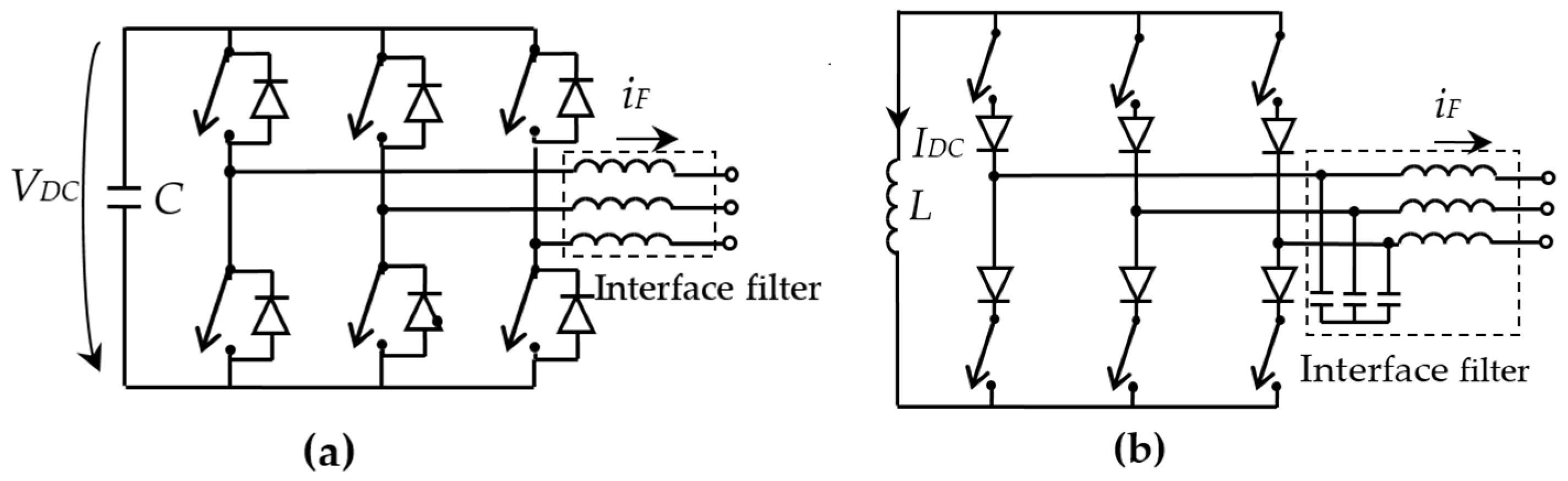
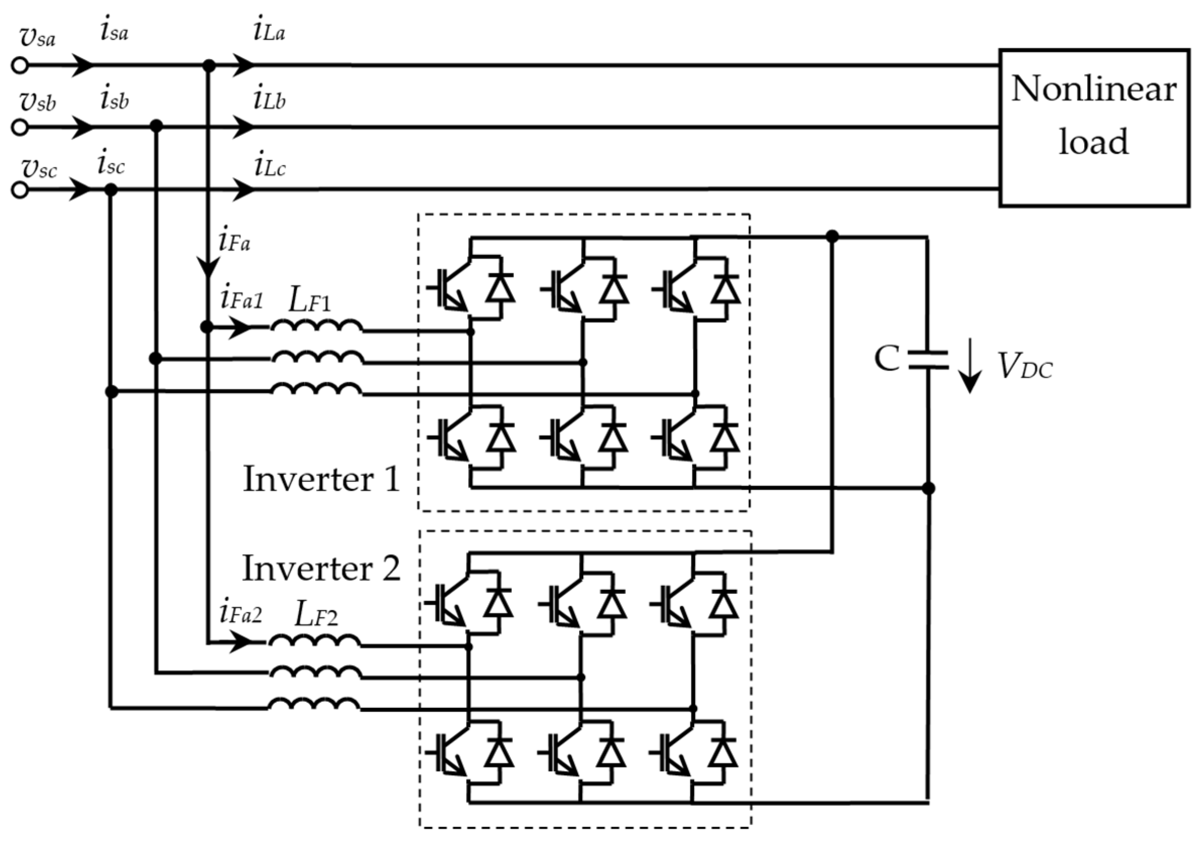
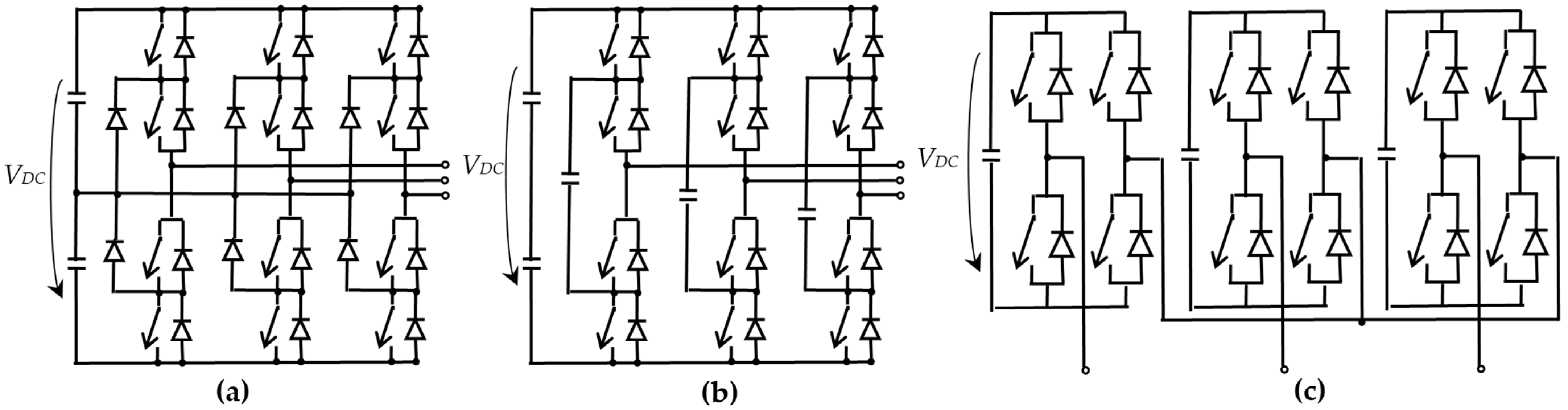


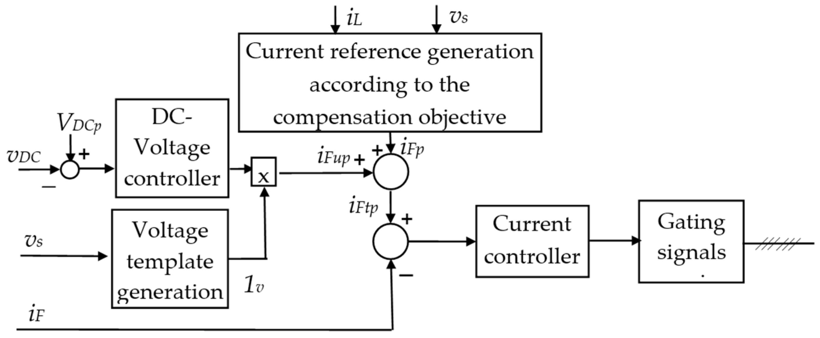


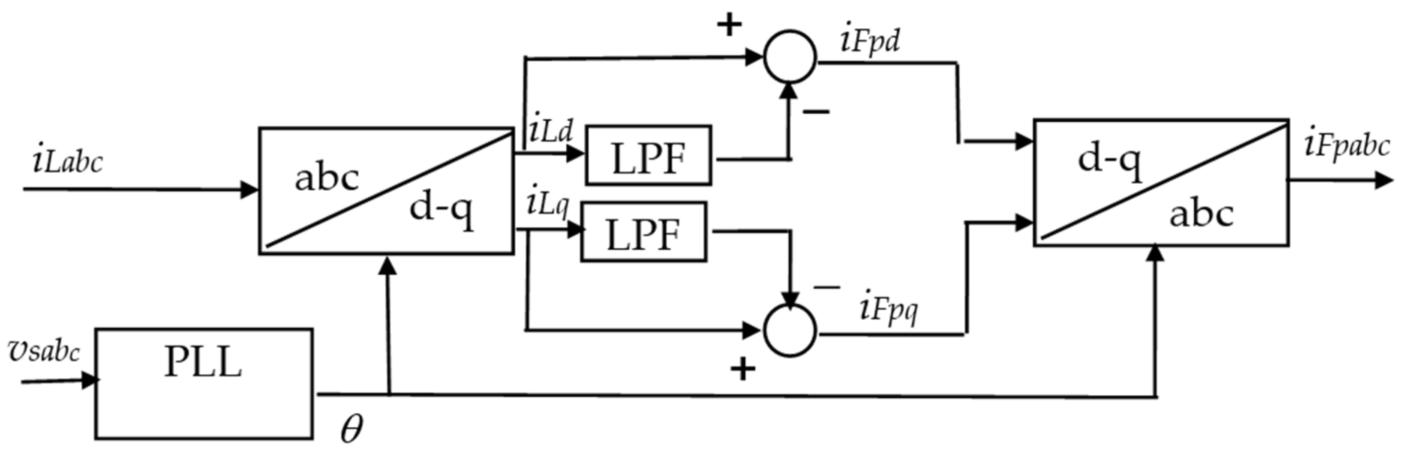
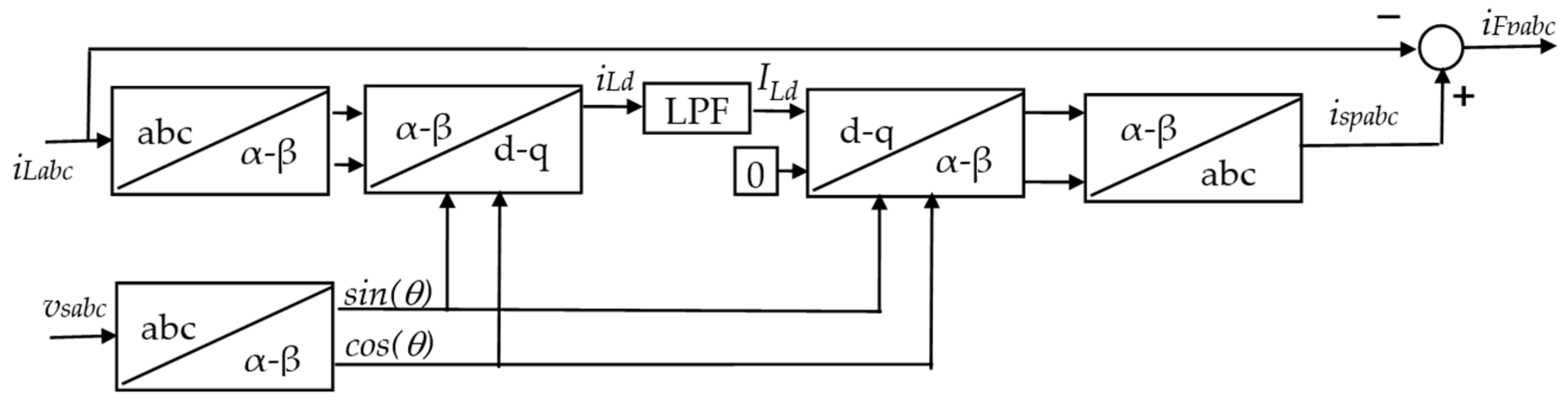
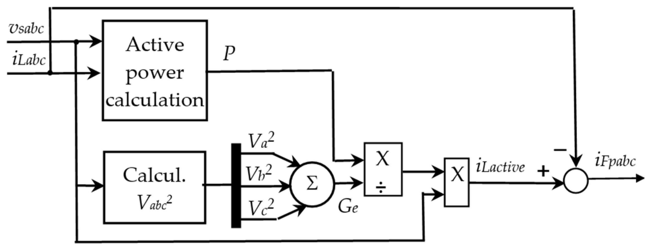
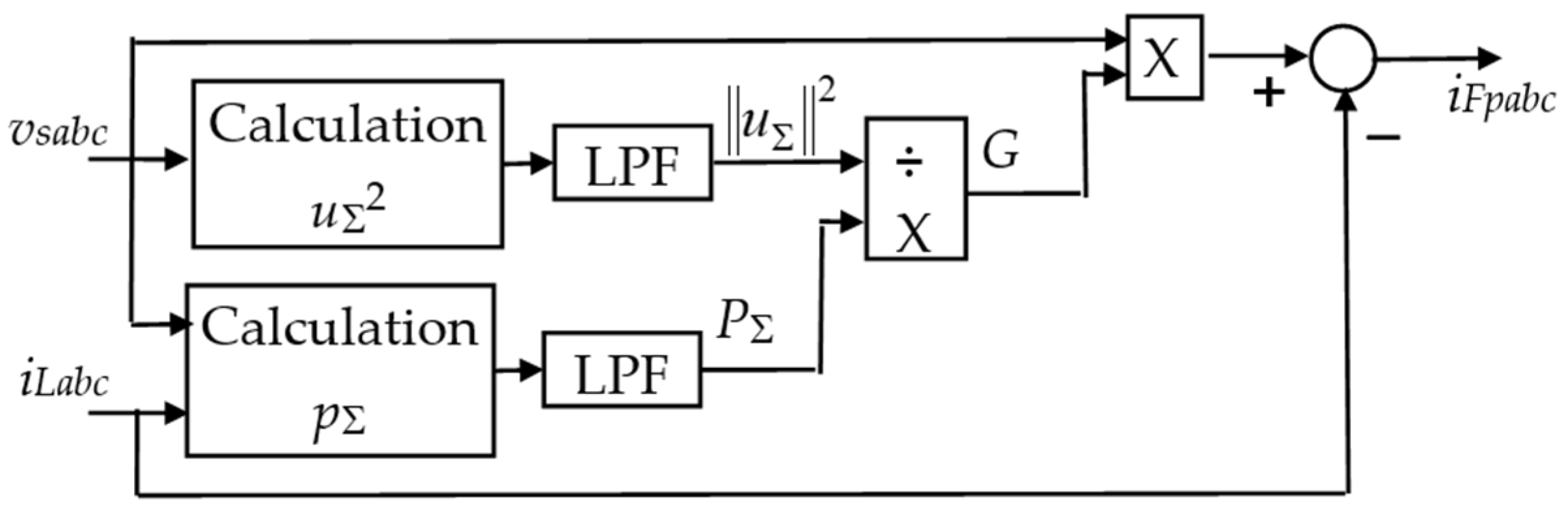

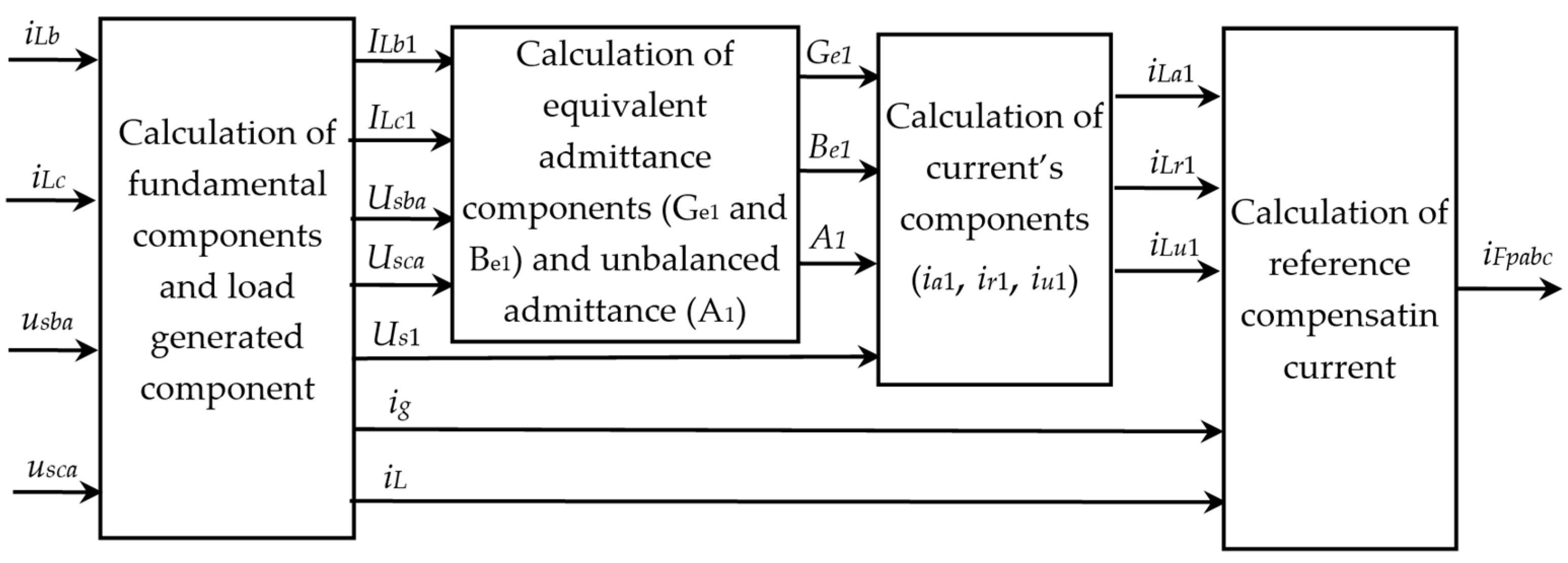
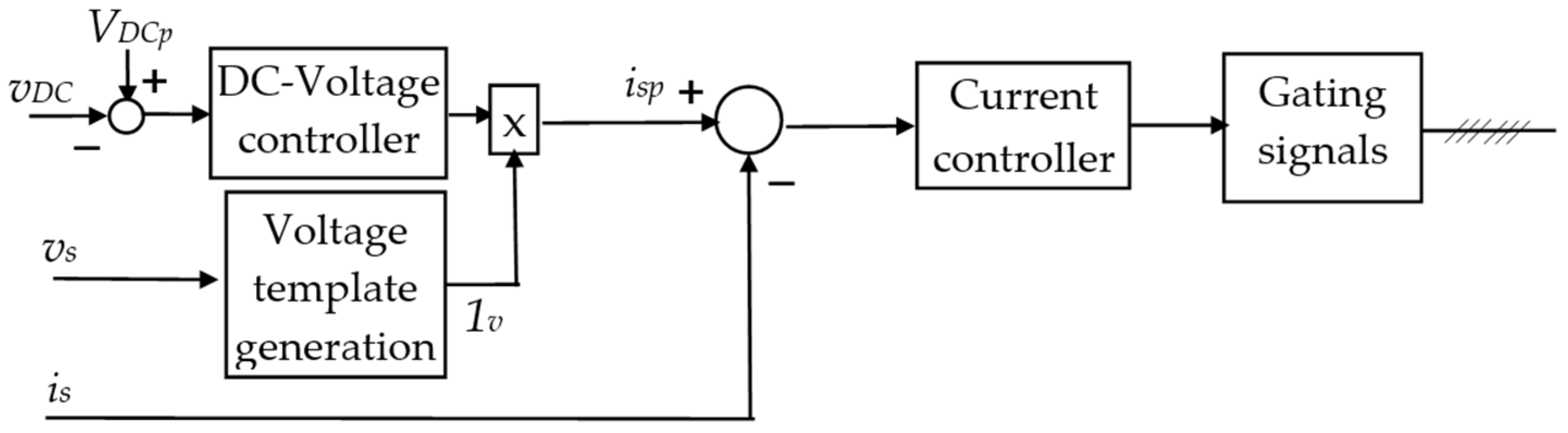
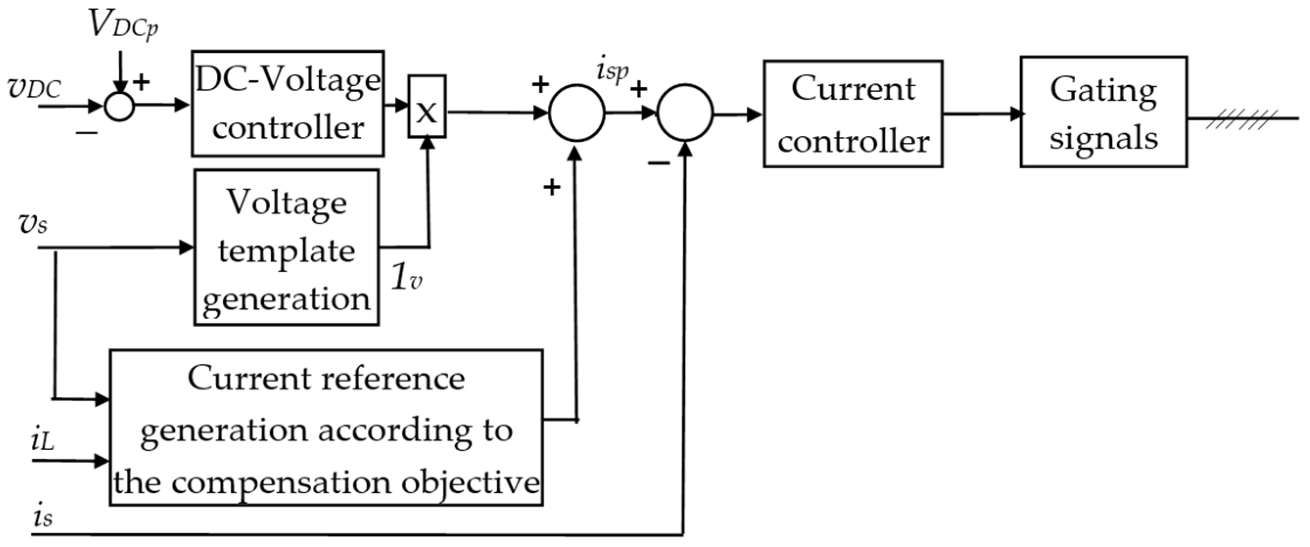
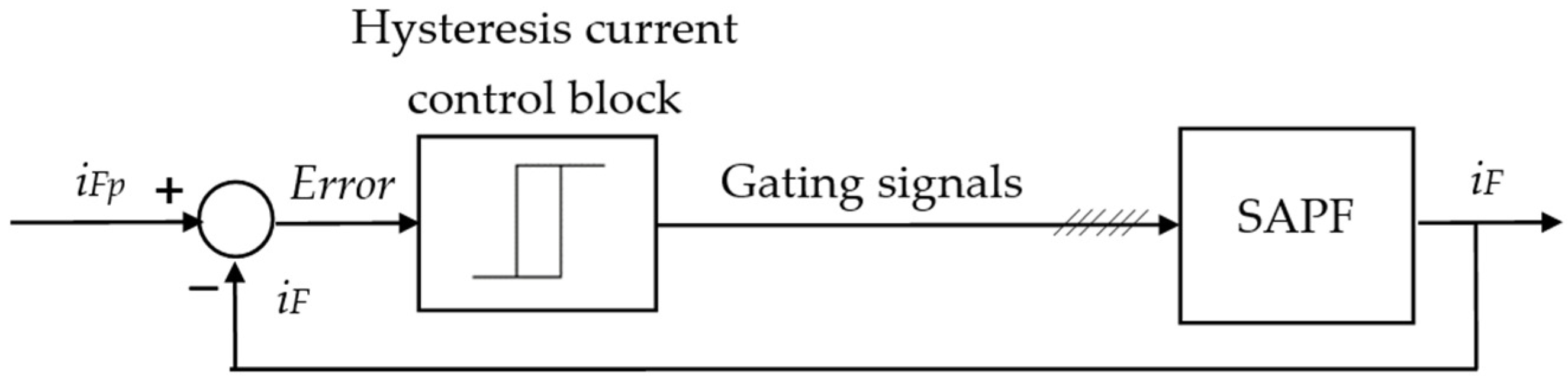
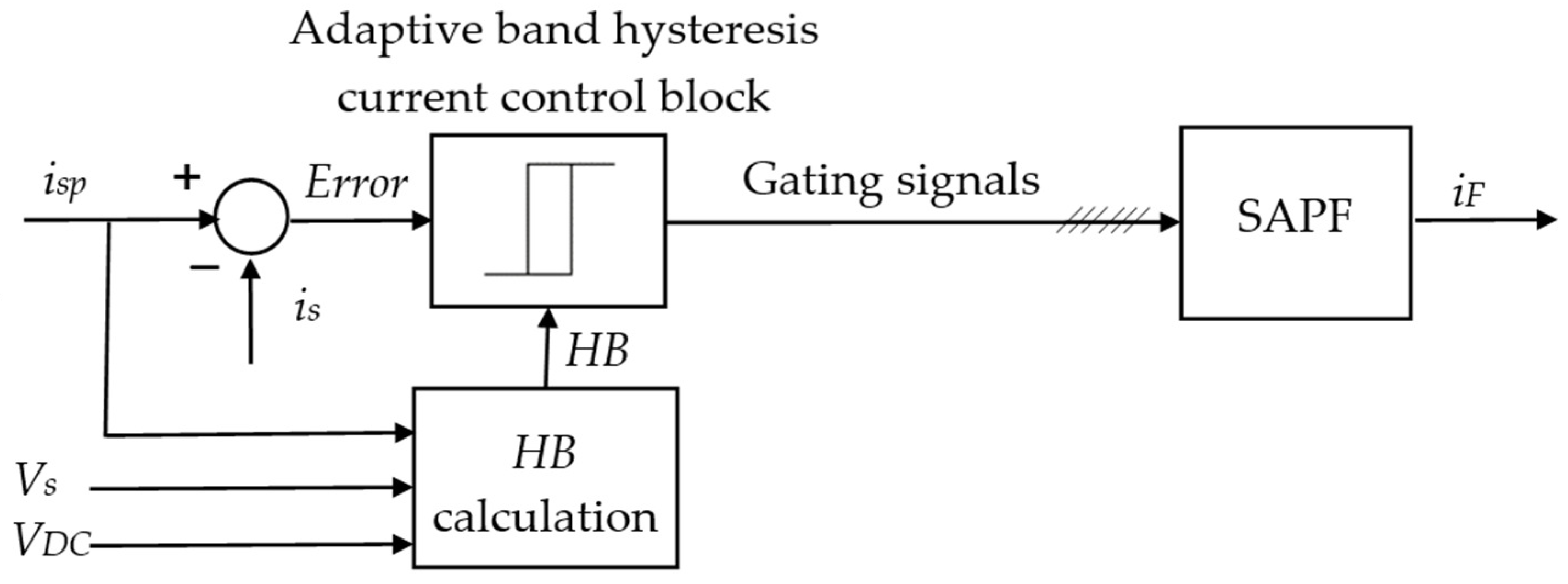


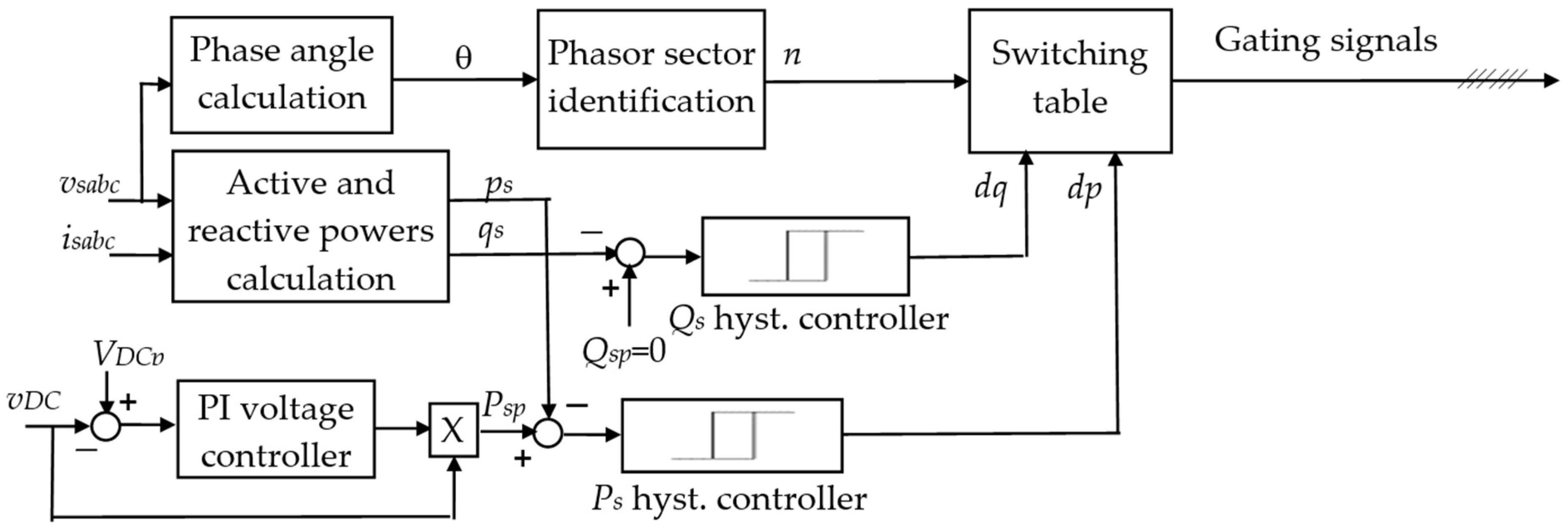


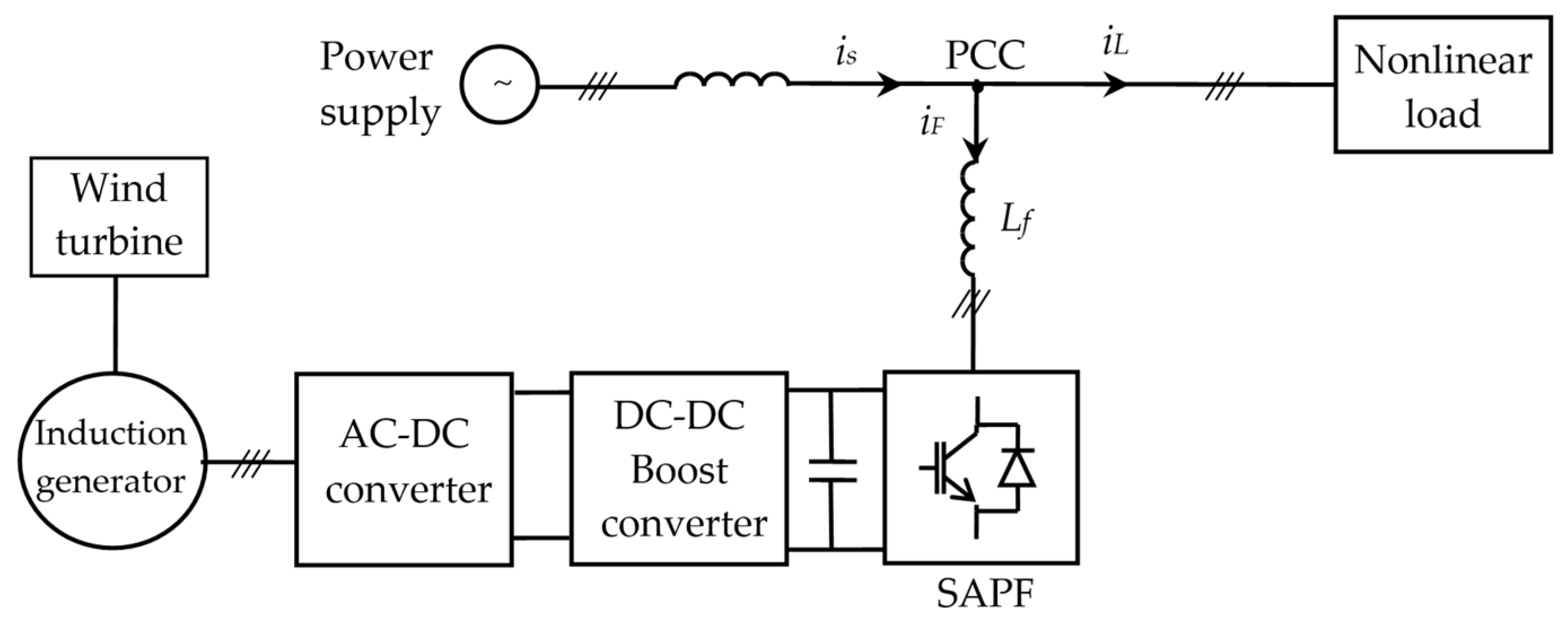
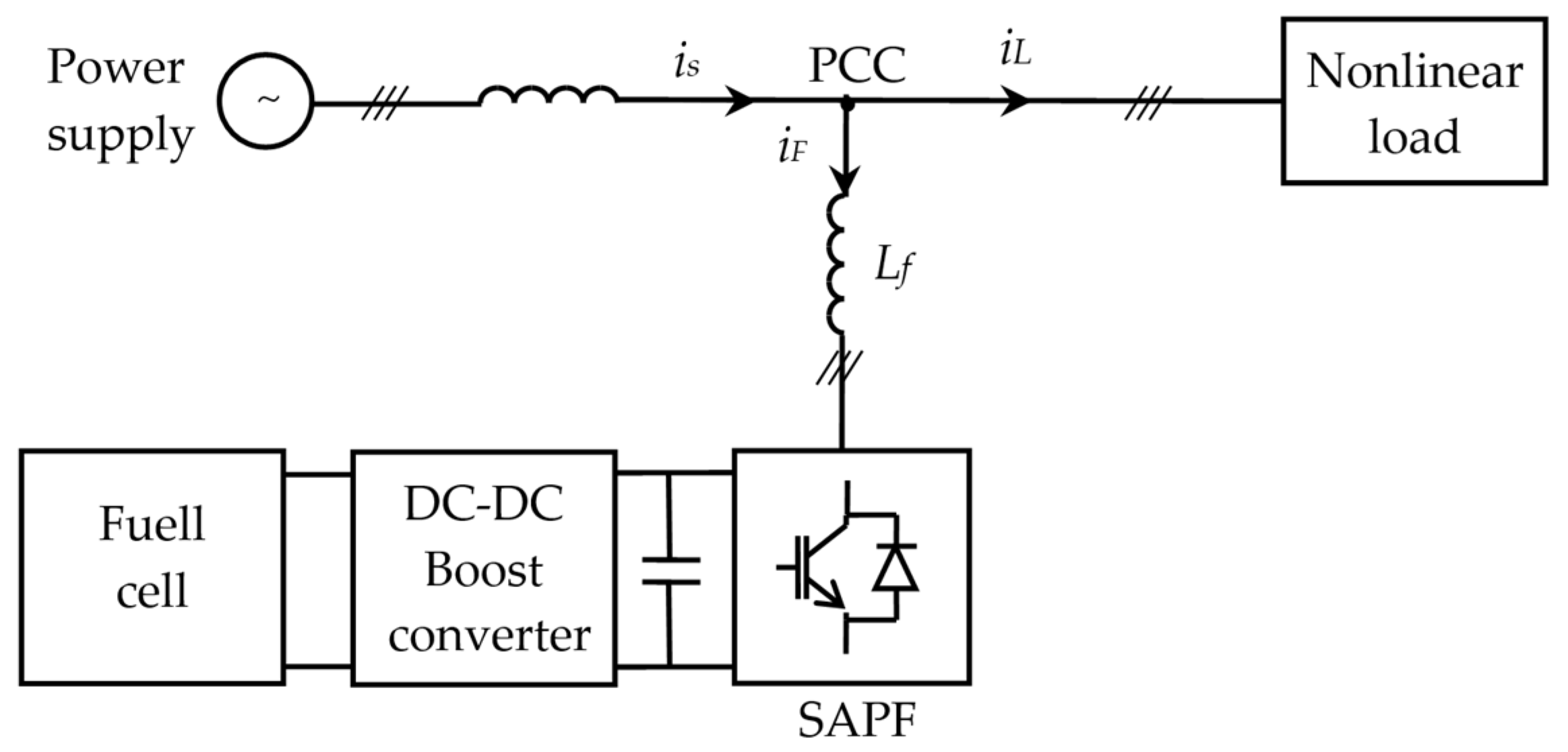

Disclaimer/Publisher’s Note: The statements, opinions and data contained in all publications are solely those of the individual author(s) and contributor(s) and not of MDPI and/or the editor(s). MDPI and/or the editor(s) disclaim responsibility for any injury to people or property resulting from any ideas, methods, instructions or products referred to in the content. |
© 2024 by the authors. Licensee MDPI, Basel, Switzerland. This article is an open access article distributed under the terms and conditions of the Creative Commons Attribution (CC BY) license (https://creativecommons.org/licenses/by/4.0/).