Article

Study on Conventional Island Retrofit Strategies for Converting Coal-Fired Power Plants to Nuclear Power Stations in China

1
China Power Engineering Consulting Group Co., Ltd., Beijing 100029, China
2
East China Electric Power Design Institute Co., Ltd. of China Power Engineering Consulting Group, Shanghai 200063, China
*
Authors to whom correspondence should be addressed.
Energies 2024, 17(12), 2912; https://doi.org/10.3390/en17122912
Submission received: 25 April 2024 / Revised: 31 May 2024 / Accepted: 10 June 2024 / Published: 13 June 2024
(This article belongs to the Special Issue Repurposing Coal Power Plants with Nuclear Power Plants)

Abstract

:
The conversion of coal-fired power plants to nuclear power stations is a potential method for decarbonizing coal power and offers a pathway for low-carbon development in China’s power industry. This paper focuses on retrofitting China’s coastal coal-fired power stations and compares the potential nuclear reactor technologies for the retrofit: China’s mainstream pressurized water reactor and the commercially operated fourth-generation high-temperature gas-cooled reactor (HTGR). The analysis compares the degree of matching between the two technologies and coal-fired power stations in terms of unit capacity, thermal system parameters, unit speed, structural dimensions, and weight, which significantly impact the retrofit scheme. The results indicate that HTGR is more compatible with coal-fired power plants and is recommended as the type of nuclear reactor technology to be retrofitted. The study selected the 210 MWe High-Temperature Gas-Cooled Reactor Pebble-Bed Module (HTR-PM) as the reactor technology for retrofitting a typical 300 MW class subcritical coal-fired unit. Based on the concept of subcritical parameters upgrading, the potential analysis and strategy study of retrofit is carried out in terms of the turbine, the main heat exchange equipment, the main pumps, and the main thermal system pipelines in the conventional island. The results indicate that the conventional island of the HTR-PM nuclear power plant has significant potential for retrofitting, which can be a crucial research direction for nuclear retrofitting of coal-fired power plants.

1. Introduction

Constructing a new power system is crucial for China to achieve carbon neutrality. The core challenge of this new system is to ensure the safe and reliable substitution of new energy for coal power, which must be retired in an orderly manner [1]. China’s power system currently relies heavily on coal power, resulting in high carbon emissions. The situation for reducing carbon emissions from coal-fired power is worrying. In addition to the early decommissioning of coal-fired power stations and reducing direct emissions through carbon capture systems, the retrofit of coal-fired power units with low-carbon technologies such as nuclear energy is also a viable option. From a functional perspective, both nuclear power and coal power can serve as base-load power sources and contribute to the power system’s peak and frequency regulation. As of June 2019, statistics show that China’s coal power units have an average service life of only 12 years, significantly lower than that of the European Union and the United States [2]. From a resource utilization perspective, decommissioning and dismantling existing coal-fired power stations is expensive due to their long remaining life. The retrofitting of coal-fired power plants to nuclear power can use resources such as grid access systems, water sources, land, transmission facilities, and some process equipment and infrastructure of existing coal-fired power plants to reduce the overall cost of nuclear power stations.
The Electric Power Research Institute (EPRI) offers a practical guide for developing nuclear energy facilities in coal plant communities, with an analytical study of the necessary steps and considerations for redeveloping nuclear power on existing coal facilities [3]. The Nuclear Innovation Alliance (NA) offers an overview of the concepts, opportunities, and challenges related to coal repowering with nuclear energy as an energy transition, including the potential for repowering with nuclear, project siting and screening, costs, licensing and regulation, and infrastructure reuse [4]. The US-DOE identified no less than 125 sites in the United States with an accumulated capacity potential of nearly 200 GWel that could profit from a C2N retrofit [5]. Qvist et al. [6] provided a technical analysis for the C2N potential in Poland, a country that currently generates more than 80% of its electricity from fossil fuels, and Bartela et al. [7,8] provided additional economic considerations for retrofitting coal-fired power plants in Poland with fluoride-salt-cooled high-temperature reactors (FHRs). Nils Haneklaus et al. [9] argue that akin to an earlier EU directive on carbon capture and storage (CCS) that made CCS readiness assessments necessary to obtain a building permit in the EU, C2N assessments could be provided by utilities of new and operating coal-fired power plants on a voluntary basis today in order to maximize the utilization of existing infrastructure for clean energy production tomorrow. Song Xu et al. investigated the potential of using nuclear heat sources to replace coal-fired boilers in existing coal power plants in China as a sustainable low-carbon development strategy. They proposed a three-stage strategy to explore the potential of repowering coal power by nuclear energy in China and analyzed the retrofit of Chinese coastal coal-fired power plants of the first stage in terms of environmental and social approvals, site requirements, seismic conditions, unit pairing, and assessment of emergency planning areas. They described the steps of nuclear power retrofit decarbonization in detail for three representative types of coal-fired units, providing validated input data to solve the blank area of China’s domestic thermal power retrofit decarbonization [10].
Investigating the compatibility of nuclear power reactor technology with coal-fired power plant systems is crucial during the nuclear retrofitting of coal power. The study on matching needs to meet two requirements: (1) Maintain the rated heat load operation based on the existing reactor design without any other modifications. (2) Reducing modifications to conventional island systems, equipment, and facilities while maximizing the use of existing assets. This paper presents a comparative study of nuclear power reactor technologies that could potentially match the retrofit of coal-fired power stations in the first stage and suggests the type of reactor technology that is recommended at the present stage. The study selected the 210 MWe High-Temperature Gas-Cooled Reactor Pebble-Bed Module (HTR-PM) as the reactor technology for the retrofit of a typical 300 MW class subcritical coal-fired unit and investigates the conversion strategy for the main equipment and systems of the conventional island.

2. Methods

The method of analysis used in this section is contrastive analysis. Contrastive analysis is a research method commonly used in scientific research to compare two or more objects, phenomena, theories, or strategies to identify similarities and differences between them to draw new insights or conclusions. The comparative analysis method consists of the following steps: (1) determining comparative parameters, (2) selecting research subjects and collecting data, and (3) conducting comparative analyses and drawing conclusions.

2.1. Reactor Matching Research Methodology for Nuclear Power Retrofit of Coal-Fired Power Plants

(1)
Comparative parameters
A nuclear power plant comprises three main components: a nuclear island, a conventional island, and a balance of plant (BOP). A coal-fired power plant comprises boiler systems, steam engine systems, and plant-wide auxiliary systems. The conversion of coal-fired power plants to nuclear energy involves replacing the boiler system with a nuclear island, which provides heat for the plant. The remaining components of the original coal-fired unit are repurposed to the greatest extent possible. In selecting the reactor technology to be employed in the conversion process, the primary criteria for matching are as follows:
MC1: Ability to fully utilize external conditions such as grid access systems and water sources for coal-fired units;
MC2: Highly compatible with the turbine thermal system of coal-fired units;
MC3: Minimize the amount of retrofit work on existing turbine building in coal-fired power stations.
Factors that impact each matching criterion more are analyzed to identify essential comparison parameters. The method of analysis is as follows:
The utilization of the grid access system commences with the determination of the capacity of the units connected to the grid system. If the capacity of the retrofitted unit exceeds the design capacity of the original access system, it may not be possible to utilize the equipment, booster stations, line feeder systems, and so forth associated with the existing access system. The generator’s output frequency is directly proportional to the speed of the turbine. Consequently, any changes in the speed of the turbine will affect the output frequency of the generator, which in turn will influence the frequency matching to the grid and the stability of the unit’s grid-connected operation. Furthermore, the disparity in rotational velocity precludes the utilization of existing generator-system-related apparatus. Consequently, to optimize the utilization of the existing grid access system, the capacity of the retrofitted units should not exceed that of the original coal power units, and the turbine speeds should also remain consistent. The utilization of the water source system is primarily concerned with the reuse of cooling system facilities, including withdrawal and drainage structures, water pump houses, and withdrawal and drainage pipes, among other components. The degree of utilization is largely contingent upon the capacity of the unit cooling system. Given that the exhaust parameters of nuclear and coal power units are relatively similar, the capacity of the cooling system is primarily determined by the size of the turbine exhaust flow. The exhaust steam flow is intimately connected to the unit power and initial steam parameters. In order to optimally utilize the existing water system, it is essential to ensure that the turbine exhaust steam flow remains unchanged following the proposed modifications.
In the context of the matching aspect of the turbine thermal system, the turbine steam inlet parameters and steam properties represent essential influencing factors. Firstly, the turbine inlet parameters determine the enthalpy drop of the steam in the turbine. A reduction in the steam inlet parameter of the turbine results in a decrease in the enthalpy drop of the steam, which in turn leads to a reduction in the work capacity of the turbine. This necessitates installing a larger flow capacity to maintain the same power conditions, a process which is challenging to achieve through retrofitting. Nuclear and thermal power units are equipped with multi-stage heat recovery systems. The closer the steam turbine inlet parameters are, the more similar the parameters of each stage of the extraction heat recovery system are theoretically, and the higher the matching degree of each stage of the equipment and piping of the heat recovery system. The nature of steam refers to whether the work medium at all turbine levels is superheated steam or saturated steam. Since saturated steam causes severe erosion and wear of materials, it is of the utmost importance to select appropriate materials and implement effective anti-erosion measures in the design of turbine through-flow components and steam piping at all levels. Consequently, the turbine inlet parameters and steam properties exert a considerable influence on the extent of reuse of turbine and thermal system equipment.
The principal equipment in the steam engine room of the coal power unit and the conventional island of the nuclear power unit is comparable, encompassing the turbine generator set, all levels of return heaters, the main pumps of the thermal system, and so forth. The size of the turbine generator set equipment determines the size of the plant. The length dimension of the turbine generator set is related to the length of the shaft system and the number of turbine cylinders. In contrast, the width dimension of the set is primarily influenced by the size of the final exhaust vane and the size of the exhaust area. An increase in the size of the turbine generator set frequently entails an increase in the overall weight of the equipment, necessitating an expansion in the size and foundation capacity of the turbine generator set base and the entire turbine room. This represents a significant challenge for retrofitting. Consequently, the retrofit should be conducted to minimize the overall size and loading of the turbine-generator set.
The preceding analyses demonstrate that the factors that exert the greatest influence on the matching criterion are the single-unit capacity, thermal system parameters, unit speed, structural dimensions, and weight. This paper presents a reactor matching study through a comparative analysis of the factors above.
(2)
Research subjects
Reference [10] proposed a three-stage strategy to explore the potential of repowering coal power with nuclear energy in terms of safety, economy, and political environment, taking into account China’s national conditions: (1) The first stage is the nuclear conversion of coal-fired power plants located directly on the coast. (2) The second stage includes retrofitting coal power plants near inland cities close to the coast, in coastal provinces that already have commercial nuclear power plants. (3) The final stage involves decarbonization of coal-fired power plants in inland cities. The first stage includes coal-fired power plants with a total installed capacity of approximately 75 GW, which have the potential for nuclear power conversion. The main single-unit power consists of subcritical and supercritical units of 300 MW class (300 MW, 350 MW) and 600 MW class (600 MW, 660 MW) [10]. Currently, China’s nuclear power units are primarily pressurized water reactors. However, the steam parameters of Generation IV nuclear power plants are more similar to those of thermal power plants. As the world’s first Generation IV nuclear power plant, the Shidao Bay High Temperature Gas-cooled Reactor Nuclear Power Plant (HTR-PM), which was officially put into commercial operation in 2023, is a very promising alternative for the conversion of coal power to nuclear power. This paper focuses on retrofitting China’s coastal coal-fired power stations in the first stage and compares the potential nuclear reactor technologies for the retrofit: China’s mainstream pressurized water reactor and the commercially operated fourth-generation high-temperature gas-cooled reactor. The analysis compares the degree of matching between the two technologies and coal-fired power stations to determine the recommended reactor technology in terms of unit capacity, thermal system parameters, unit speed, structural dimensions, and weight, which have a more significant impact on the retrofit scheme.
The pressurized water reactor (PWR) nuclear power units that have been put into operation in China in recent years have a single-unit power of more than one million kilowatts. These units are mainly of the following types: EPR, AP1000, CPR1000, and VVER-1000. The EPR is a third-generation PWR reactor that PharmaTech and Siemens have developed. Taishan is the first large-scale commercial nuclear power plant in China to be constructed using EPR Generation III technology. The AP1000 is a non-energetic pressurized water reactor nuclear power plant developed by Westinghouse. It is an extension of the AP600 model design and incorporates a non-energetic safety system that allows for a relatively large simplification of the system, a reduction in the number of devices, and an increase in the safety and economics of nuclear power plants. The first AP1000 nuclear power units in China have commenced operation at the Sanmen and Haiyang facilities in Zhejiang and Shandong provinces, respectively. The CPR1000 is a “second-generation improved” nuclear power technology program developed by China. It is based on the introduction, digestion, and absorption of foreign advanced technologies, combined with progressive improvements and independent innovation over the past two decades. The program has advanced, mature, and good economic characteristics. This type of reactor is employed in the Ling’ao II, Hongyanhe, Ningde, and Yangjiang nuclear power projects of CGNPC, as well as the Fuqing and Fangjiashan nuclear power projects of CNNC. The two-megawatt units of China’s Tianwan I nuclear power plant are Russian VVER-1000 pressurized water reactors. Construction of the project commenced in 1999, with the two units entering commercial operation in May and August 2007, respectively.
The parameters and capacities of these reactors exhibit considerable variability, with the principal thermal parameters presented in the Table 1 below.
After the first concrete was poured on 9 December 2012 at the Shidao Bay site in Rongcheng, Shandong Province, China, the world’s first high-temperature gas-cooled reactor pebble-bed module (HTR-PM) demonstration power plant was officially put into commercial operation in December 2023. The HTR-PM consists of two pebble-bed reactor modules coupled with a 210 MWe steam turbine. Each reactor module includes a reactor pressure vessel (RPV); graphite, carbon, and metallic reactor internals; a steam generator; and a main helium blower. The thermal power of one reactor module is 250 MWth, the helium temperatures at the reactor core inlet/outlet are 250/750 °C, and the main steam parameters are at 13.24 MPa/566 °C. The HTR-PM employs chemically inert helium as the coolant, graphite as the neutron moderator, and ceramic-coated pellet spherical fuel elements. Helium is utilized as the working medium in the first cycle. Following the heating of helium to 750 °C within the reactor core, it is transported to the steam generator, where it is used to heat the feed water from the conventional island, resulting in the generation of high-temperature steam. This high-temperature steam then enters the turbine generator, where it is used to produce electricity. The cooled helium gas is pressurized by the helium recirculation fan located on the top of the steam generator shell and flows back to the reactor, thereby forming a closed cycle. The HTR-PM600 high-temperature gas-cooled reactor nuclear power plant is based on the technology of the high-temperature gas-cooled reactor pebble-bed module (HTR-PM) demonstration project. It utilizes proven HTR-PM reactor and steam generator modules with a thermal power of 250 MWth and power generation of approximately 100 MWe per module. Six modules are connected to a steam turbine in parallel, forming a 600 MWe nuclear power plant. In addition, its system configuration in the nuclear island is identical to that of the HTR-PM. The concept of a ventilated low-pressure containment (VLPC) is unchanged; however, a large circular VLPC accommodating all six reactor modules is adopted rather than the previous small-cavity-type VLPC, which contains only one module, as defined for the HTR-PM [11].
Table 2 presents the main technical parameters of the HTR-PM and HTR-PM600.
Regarding China’s target coal-fired units in the first stage, it can be observed that most units in the 200 MW class and below are ultrahigh-pressure units. In contrast, both supercritical and subcritical units exist in the 300 MW and 600 MW classes, with some of the units in the 600 MW class being ultra-supercritical units. Typical units of each class are selected as the research object of this section.
Figure 1 compares important parameters and matching methodology between nuclear and coal-fired power plants, assuming that the existing reactor design remains unchanged.

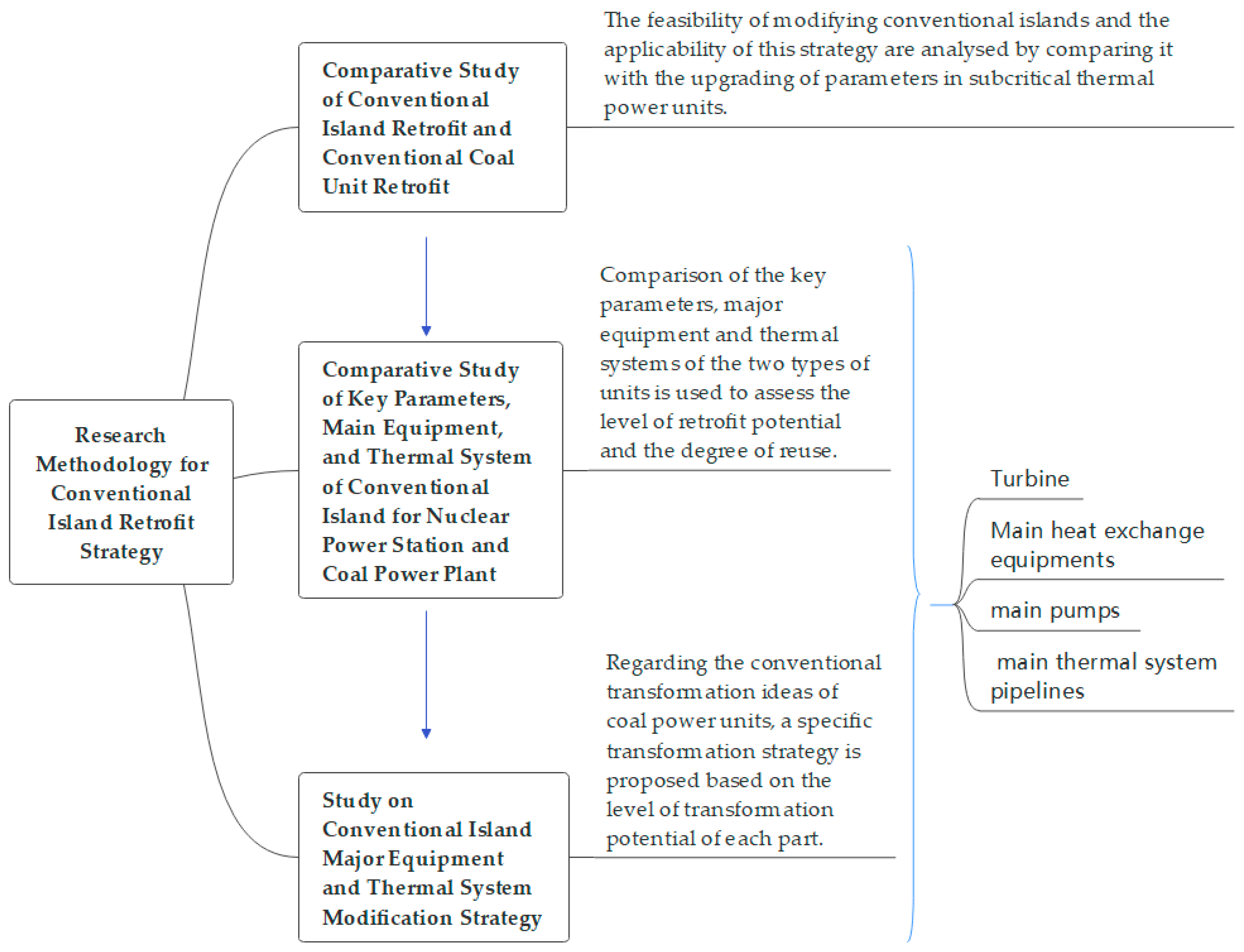
2.2. Research Methodology for Conventional Island Retrofit Strategy

  • Comparative parameters
The conventional island of nuclear power and the steam turbine building of a coal-fired power station are similar in function and composition. The conventional island retrofit strategy research compares the components of the nuclear power conventional island and the coal-fired power station steam turbine building. This analysis aims to identify similarities and differences between the two, assess the feasibility of each retrofit component, and formulate a corresponding retrofit strategy. The following aspects are analyzed in detail:
The turbine unit’s heat balance is paramount in determining the entire process system of the steam turbine room. Consequently, the number, type, and technical parameters of the process equipment are also contingent upon this balance. In the case of nuclear power plants, the heat balance calculation of the turbine unit is based on the thermal analysis and calculation of the second-loop steam-water mass Rankine cycle. This is carried out by the fundamental principles of engineering thermodynamics, including the conservation of mass and energy. The calculation utilizes the import and export parameters of the steam generator on the nuclear island side, the structural form of the second-loop thermal system of the conventional island, and the thermal characteristics of the critical equipment and the parameters of the cold end as inputs, and it takes the parameters of the thermal state of the second-loop and the economic indicators of the unit such as the electric power as outputs. The methodology employed to calculate the heat balance of a steam turbine in a coal power unit is analogous to that employed in a nuclear power unit, with the exception that the heat source is altered from the steam generator of the nuclear island to the boiler. In the context of the design of new units and the retrofitting of existing units, the heat balance calculation of the turbine unit represents a fundamental reference basis. Comparative analysis of the heat balance can be employed as a preliminary assessment of the feasibility of steam turbine thermal system modification for both types of units.
Process equipment and piping systems: The principal process equipment in the steam turbine building comprises turbine units, various pieces of heat exchange equipment, and a range of pumps. The principal selection parameters of the steam turbine encompass thermal parameters, characteristics of the working medium, structural characteristics, and the selection of materials. The selection of heat exchange equipment is primarily based on heat exchange capacity, structural strength, material selection, etc. The selection of pumps is based on flow rate, head, structural strength, and material selection, among other factors. The selection of heat system piping is primarily concerned with the system process, through-flow capacity, piping strength, material selection, and other related factors. By undertaking a comparative analysis of each piece of equipment and pipeline in terms of the selection parameters, it is possible to determine the feasibility of transformation and subsequently formulate a corresponding transformation strategy.
2.
Research subjects
The thermal system flow chart of the conventional island of the 210 MWe high-temperature gas-cooled reactor pebble-bed module (HTR-PM) nuclear power plant demonstration project is presented in Figure 2. The turbine is a full-speed, single-shaft, two-cylinder, two-exhaust steam turbine with no intermediate reheat. The regenerative system comprises a five-stage system comprising three low-pressure heaters, a deaerator, and a double-row high-pressure heater. The feedwater system comprises three motor-driven feedwater pumps with a capacity of 100 percent of the rated feedwater flow rate of a single reactor steam generator. The condensate system is equipped with three electric fixed-speed condensate pumps, each with a capacity of 50 percent.
A 300 MW subcritical unit of a typical project was selected as the target coal-fired unit, and the thermal system flowchart of the unit is presented in Figure 3. The steam turbine is a subcritical pressure, single reheating type, single-shaft, two-cylinder, and two-exhaust, condensing steam turbine. The turbine unit has eight stages of unadjustable extraction. The first-stage, the second-stage, and the third-stage extraction are supplied to three HP heaters, correspondingly. The fourth-stage extraction is supplied to the BFP steam turbine, deaerator, and auxiliary steam system. The fifth-stage, the sixth-stage, the seventh-stage, and the eighth-stage extraction are supplied to four LP heaters, correspondingly. Two steam-driven pumps with 50% of the total capacity of feed water and one motor-driven pump with 30% of the total capacity of feed water are equipped in the feed water system. There are two vertical motor-driven condensate pumps in the condensate system; one is on duty, and the other is on standby.
The methodology for the conventional island retrofit strategy study is presented in Figure 4.

2.2.1. Conventional Coal Unit Retrofit

Conventional island retrofit has many similarities with conventional coal unit retrofit and, in a sense, can be regarded as a kind of coal unit retrofit. From the perspective of the overall power station, the conversion from coal to nuclear power requires the removal of the boiler and its replacement with a new nuclear island. However, from the perspective of the turbine and thermal system, there are many similarities between the two processes regarding the idea, method, and content of the transformation.
Research on coal unit retrofits in China focuses mainly on flexibility transformation and energy-saving reconstruction, including innovation of heat supply and capacity-increasing. In recent years, energy-saving and emission-reducing technologies for coal power units have been significantly advanced due to energy structure adjustments and related policies. The industry has seen the emergence of the technology of upgrading subcritical units to super (ultra) critical units, which has gradually evolved into the technology of upgrading subcritical unit parameters [12]. The technology focuses on subcritical units, raising only the steam temperature while keeping the main steam pressure basically unchanged. In recent years, some coal power units in China have upgraded their parameters, confirming the feasibility of this transformation technology. The retrofit units have a capacity of 300 MW and 600 MW subcritical units. The turbine’s main steam and reheat steam inlet temperatures have been increased from 538 °C to 566 °C, while the main steam pressure remains unchanged [13,14,15,16,17].
The technology of upgrading parameters of sub-critical units is a complex systematic project involving boilers, turbines, and thermal systems of a power plant [18]. In addition to upgrading high-temperature components, the most critical aspect of turbine modification is the through-flow transformation. This transformation has been carried out in China for many years, and the major domestic turbine manufacturers have many transformation achievements, with the technology being very mature. Retrofitting the primary thermal system requires checking the original system’s equipment and pipework capacity, with replacement where necessary and without technical limitations. The feasibility of conventional island retrofit methodology and the applicability of the retrofit strategy are analyzed by comparison with the parameter upgrading retrofit of subcritical thermal power units.

2.2.2. Retrofit of Conventional Island Turbine

Whether for coal or nuclear power units, the turbine is a crucial equipment, and its structural type and size largely determine the size of the whole turbine room. The research analyzes the potential for turbine transformation from the perspectives of main technical parameters and structural characteristics. It also explores the transformation strategy for high-pressure cylinders, low-pressure cylinders, main steam valves, and steam guide tubes.

2.2.3. Retrofit of Conventional Island Main Heat Exchange Equipment

The conventional island of a nuclear power plant includes several main pieces of heat exchange equipment such as high-pressure heaters, low-pressure heaters, deaerator, condenser, and so on. These pieces of equipment are also present in coal-fired units and function similarly. The two types of units have different turbine capacities and steam extraction parameters. To investigate the retrofit strategy of these heat exchangers, the analysis method for heater adaptability [19,20] in upgrading nuclear or coal power units was referred to. The analysis of the heat exchanger modification was conducted as described below.
The heat load margin is used to evaluate the adaptability of the retrofit program for high-pressure heaters, low-pressure heaters, deaerator, and condenser. The formulas for calculating the heat load Q and heat load margin Q are as follows:
Q = G w ( h 0 h i ) ,
Q = Q 1 Q 2 Q 2 × 100 %  
where
G w —flow rate of the water side of the heat exchanger, kg/s;
h 0 —enthalpy of heat exchanger outlet water, kJ/kg;
h i —enthalpy of heat exchanger inlet water, kJ/kg;
Q 2 —heat load of the original design programme, kJ/kg;
Q 1 —heat load of the retrofit programme, kJ/kg.
The heat load margin has a physical significance: a positive value indicates a margin in the heat exchange area, while a negative value indicates that the heat exchange area is insufficient. In engineering, if the heat load margin is negative and its absolute value is more than 10%, the heat exchanger should be replaced.

2.2.4. Retrofit of Conventional Island Main Pumps

The conventional island of a nuclear power plant includes several main water pumps, such as feed water pumps, condensate pumps, and open and closed circulating cooling pumps. These pumps serve the same functions in coal power units. The critical technical parameters, including configuration, flow rate, and head of the pumps before and after the retrofit, are compared to analyze the retrofit potential and strategy.

2.2.5. Retrofit of Conventional Island Main Thermal System Pipelines

The conventional island’s main thermal system piping includes main steam piping, main feedwater piping, condensate piping, steam extraction piping, and open and closed loop cooling water piping. The main system piping of the target coal-fired power plant was analyzed in terms of pipe wall thickness, flow rate, and materials for the modification potential and strategies based on the piping parameters and materials of the conventional island of the HTR-PM nuclear power plant.
By the Code for design of steam/water piping of fossil-fired power plant (DL/T 5054-2016) [21], the formula for calculating the adopted wall thickness of the straight pipe, based on its outer diameter, is as follows:
S m = p   D 0 2 σ t   η + 2 Y p + C  
S q = S m + C 1 + 0.5   Δ D 0  
where
S m —minimal wall thickness of the straight pipe, mm;
p —design pressure, MPa;
σ t —safe allowable stress of the steel products at design temperature, MPa;
D 0 —external diameter of the pipe, where nominal external diameter is adopted, mm;
Y —reduction coefficient of the temperature;
η —reduction coefficient of the allowable stress;
C —suitable appended thickness after considering erosion, abrasion, and mechanical strength, mm;
C 1 —added value for wall thickness’ negative deviation, mm;
S q —adopted wall thickness of the straight pipe, mm.
The formula for calculating the medium flow rate in the pipe is as follows:
ω = 4 Q π D i 2    
where
ω —medium flow rate, m/s;
Q —volume flow rate of medium, m3/s;
D i internal diameter of the pipe, m.

3. Results and Discussion

3.1. Targeted Coal Power Units and Matching Reactor Technologies

Table 3 compares the main technical parameters of coal-fired power plants with those of pressurized water reactors and high-temperature gas-cooled reactor nuclear power plants. The data employed in the comparative analyses were derived from the design technical parameters of typical projects for each type of unit. The following discussion elaborates on the comparison.
  • Single-unit capacity
The nuclear decarbonization of China’s coal-fired power plants in the first phase was based on four main types of units: 300 MW, 350 MW, 600 MW, and 660 MW. The Shandong Shidao Bay High Temperature Gas-cooled Reactor Nuclear Power Plant Demonstration Project (HTR-PM) is currently in commercial operation. It is a nuclear power plant with an installed power of 210 MWe. The heat sources are provided by two reactor modules with a thermal power of 250 MWt [22]. Currently, the technical program design and corresponding research for the 600,000 kilowatt-class high-temperature gas-cooled reactor (HTGR) nuclear power plant is being investigated on the basis of the completion and operation of the HTR-PM demonstration power plant [11]. High-temperature gas-cooled reactor nuclear power plants are comparable in unit power to coal power units in the first phase. Currently, third-generation pressurized water reactor nuclear power plant units have a unit power of 1000 MW and above, which is generally larger than that of coal power units in the first phase. As a result, the capacity of the units is poorly matched.
2.
Thermal system parameters
Typical steam admission parameters for steam turbines in coal-fired units in the first phase are 13.2 MPa/535 °C/535 °C (ultrahigh pressure), 16.7 MPa/535 °C/535 °C (subcritical), and 24.2 MPa/566 °C/566 °C (supercritical). The main steam and most of the extraction steam are superheated, and only the extraction steam in the last stages of the low-pressure cylinder is wet steam. The steam inlet parameter for HTGR nuclear power plant turbine is 13.24 MPa/566 °C, with the same pressure as an ultrahigh-pressure unit and the same temperature as a supercritical unit. Some turbines used for industrial power generation have employed parameters similar to those of high-temperature reactors. These turbines are based on typical thermal turbines and have a high potential for retrofitting. The main steam and most of the extraction steam of the HTGR unit is superheated steam, and only the extraction steam in the last few stages of the low-pressure cylinder is wet steam, which is more similar to that of a thermal power plant. Pressurized water reactor (PWR) nuclear power units have lower initial parameters and higher humidity than coal power units. The main steam is saturated with slight humidity (pressure is generally 5 MPa–7 MPa, temperature is 268–290 °C, humidity is 0.25–0.5%). This is not well suited to coal power turbines. Pressurized water reactor (PWR) nuclear units have lower initial parameters and higher humidity than coal units, which are incompatible with coal power turbines.
3.
Turbine speed
The turbines in coal power units and HTGR units are full-speed machines operating at 3000 r/min. However, the turbines in China’s pressurized water reactor nuclear power plants, with single-unit power of 1000 MW and above, are primarily half-speed machines operating at 1500 r/min. This is a significant difference from the turbines used in coal power plants.
4.
Unit structure, dimensions, and weight
The turbine steam intake and exhaust volumes for units of the same power are comparable between HTGR units and coal power subcritical/supercritical units due to the similar enthalpy drop of steam in their turbines. Therefore, the two types of units have similar numbers of cylinders, low-pressure cylinder exhaust areas, and final-stage blade sizes. The overall size and weight of the turbine units are also comparable, making them suitable for retrofitting. PWR nuclear power plants have a larger steam flow rate because of the small enthalpy drop of steam in the turbine. The low-pressure cylinder exhaust area of PWR is about twice as large as that of a coal-fired power plant for the same power conditions, with a larger final blade size or a larger number of low-pressure cylinders. The retrofit will require an increase in the size of the turbine base and the entire plant due to the larger size and weight of the turbine unit. This will make retrofitting more challenging.
The analysis shows that HTGR units are more compatible with coal power units in terms of single-unit capacity, thermal system parameters, turbine speed, unit size, weight, etc. HTGR is recommended as a compatible reactor technology type for nuclear conversion of coal power.

3.2. Conventional Island Retrofit Strategy

This section selects the 210 MWe High-Temperature Gas-Cooled Reactor Pebble-Bed Module (HTR-PM) as the reactor technology for the retrofit of a typical 300 MW class subcritical coal-fired unit and analyses the conversion strategy for the conventional island.

3.2.1. Conventional Coal Unit Retrofit Strategy

A comparison of the main parameters of the two types of retrofits is shown in Table 4:
The comparison shows that the two types of retrofits are similar in terms of inlet steam temperature, turbine modification, major auxiliary equipment, and system piping. The difference is that the turbine inlet steam pressure of the HTR-PM unit is reduced compared to a subcritical coal unit, and this reduction alone does not create a safety issue for the original coal unit systems and equipment. Removing the reheat system and reducing regenerative system numbers are modifications that will create space for additional systems. In summary, the conventional island retrofit strategy can be improved using the idea of the upgrading subcritical unit parameters retrofit.

3.2.2. Turbine Retrofit Strategy

  • Technical parameters of steam turbine
Table 5 displays the main technical parameters of the turbines for both types of units. The data presented in the table were derived from the design data of actual projects for both types of units.
Both types of units have full-speed, single-shaft, two-cylinder, two-exhaust, condensing steam turbines. The high-pressure inlet steam temperature and pressure and low-pressure inlet steam pressure levels of the turbines are relatively close to each other. The main flow rate of steam, exhaust steam flow rate, and regenerative system numbers in the HTR-PM unit are lower than those in the coal power unit. Therefore, the HTR-PM turbine flow capacity and structure size are slightly smaller.
2.
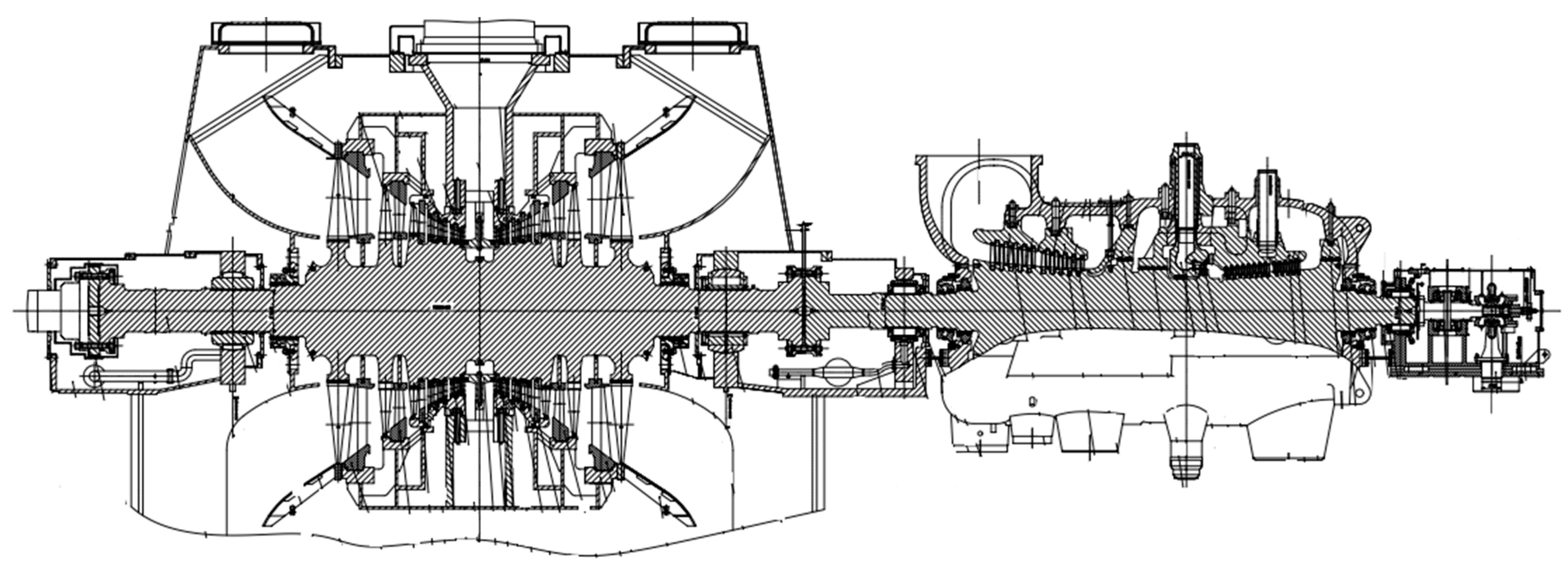
Structural characteristics of steam turbine
Table 6 shows a comparison of the structural characteristics of the turbines for both types of units. The data presented in the table were derived from the design data of actual projects for both types of units.
The HTR-PM unit’s turbine comprises a one-way flow HP cylinder and a bidirectional flow LP cylinder. The turbine’s high-pressure and low-pressure rotors are supported by double bearings. There are three bearing housings in total: one at the front end of the turbine, one at the regulator side of the LP cylinder, and one at the motor side of the LP cylinder. This is basically the same as the 300 MW subcritical unit turbine in terms of the number of cylinders, shaft system, supports, and other overall structural types. Figure 5 and Figure 6 show the longitudinal sections of the turbine for both types of units.
3.
Turbine Retrofit Strategy
  • High-pressure cylinder:
The design of the high-pressure module of the turbine in the HTR-PM unit is based on the high- and medium-pressure modules of established ultra-high-pressure thermal power units. The retrofit strategy for the HP cylinder focuses on modifying through-flow and accounting for the need to upgrade high-temperature component materials. The coal unit has a combined high- and medium-pressure cylinder with no support bearing between them. This means that converting the high- and medium-pressure cylinder into a high-pressure cylinder is not restricted by intermediate support conditions. The high-pressure cylinder of the steam turbine in a coal-fired power unit has more throughflow stages and a larger steam flow rate. Therefore, the span and opening size of the base for high-pressure cylinder in the original unit should be able to meet the space requirements for the arrangement of the HP cylinder after the modification. The modification strategy is to carry out the following scope of modification under the premise of keeping the original bearing seat span and foundation unchanged: replacement of high- and medium-pressure rotors, outer cylinders, high-pressure inner cylinders, regulating stage nozzles, all levels of moving blades and spacers, shaft seals, etc. At the same time, it is necessary to fully consider the thermal expansion of the unit. The modification involves canceling the original medium-pressure inlet and high-pressure exhaust port, relocating the original medium-pressure exhaust port to the high-pressure exhaust port, and altering the number and location of the extraction ports.
The high-pressure inner and outer cylinders of the 300 MW subcritical unit steam turbine are made of ZG15Cr1Mo [27] or ZG15Cr2Mo1 [28]. After the main steam temperature increased from 538 °C to 566 °C, it is necessary to consider upgrading high-temperature components. The material for the inner cylinder can be changed to ZG15Cr1Mo1V, which is the same as the high-pressure inner cylinder of the supercritical unit. ZG15Cr2Mo1 can be selected for the outer cylinder due to the steam temperature of about 425 °C [23].
  • Low-pressure cylinder:
The exhaust volume flow rate of the low-pressure cylinder of the HTR-PM turbine is comparable to that of a 300 MW subcritical thermal turbine. The low-pressure cylinder module of the HTR-PM turbine is optimized based on the low-pressure cylinder modules of 300 MW grade thermal turbines that have a large number of mature operating results. Both adopt a bidirectional flow arrangement with the same number of through-flow stages, structure type, height of the last blades, and LP cylinder exhaust area. Therefore, the size of the LP cylinder should be equivalent. Thus, the span and opening size of the base in the original unit should be able to meet the space requirements for the arrangement of the LP cylinder after the modification. The strategy for transformation aims to maintain the low-pressure outer cylinder as much as possible while keeping the original bearing seat span and foundation unchanged. This will involve the through-flow transformation of the low-pressure rotor, low-pressure inner cylinder, low-pressure movable blades at all levels, and each section’s spacer and shaft seals.
The low-pressure steam inlet parameters for the HTR-PM unit’s turbine are 0.7732 MPa and 200.98 °C. These values are lower than the inlet parameters for the low-pressure cylinder of a conventional coal turbine. Therefore, the LP cylinder components for the HTR-PM unit are made of the same materials as those used in a coal-fired turbine. It is important to note that the HTR-PM unit turbine does not have a reheat system. As a result, the overall humidity of the LP cylinder is high. Therefore, any modifications to the low-pressure end-stage must take into account dehumidification and water corrosion resistance measures.
  • Main steam valve and control valve:
The HP cylinder of the HTR-PM unit turbine has four symmetrically arranged inlets in its upper and lower halves. The steam distribution mechanism is also symmetrically arranged on the left and right sides, with one main steam valve and two control valves on each side [23]. The main steam valve and control valves are located and shaped similarly to that of the 300 MW subcritical unit turbine. Due to single reheat, coal power units have additional medium-pressure inlet steam control valves compared to HTR-PM unit turbines. These components must be removed during retrofitting. Figure 7 illustrates the arrangement of the main steam valve and control valves for both types of units.
The main steam valve and control valve set of the HTR-PM unit turbine are designed using the 150 MW ultra-high pressure thermal power turbine valves as the mother design module [29]. This structure is also commonly used in the 300 MW class subcritical unit turbine. The position, number, and type of valve supports are also basically the same for both types of units, so that the valve foundation can be used for renovations. As the main steam temperature was increased to 566 °C, the valve body material should be changed from ZG15Cr2Mo1 to ZG15Cr1Mo1V to meet the valve’s high temperature strength and thermal stress requirements. The materials for the high temperature components inside the valve also need to be upgraded to meet the high temperature performance requirements.

3.2.3. Retrofit Strategy for Conventional Island Main Heat Exchange Equipment

The HTR-PM unit’s conventional island thermal system is a five-stage steam extraction regenerative system with two side-by-side first-stage high-pressure heaters, one deaerator, and three low-pressure heaters [30]. The thermal system of a 300 MW class subcritical coal-fired unit consists of an eight-stage steam extraction regenerative system that includes three HP heaters, one deaerator, and four LP heaters. The condenser for both types of units is a single-shell, dual-flow, surface-cooling design. The condensate temperature rise is consistent, and a low-pressure regenerative system using three or four levels is theoretically possible. The high-pressure regenerative system in the HTR-PM unit has two fewer high-pressure heaters compared to the coal unit due to the lower feedwater temperature of about 204 °C. To compare the two types of units, we analyzed the heaters with similar design parameters, as the number of regenerative system stages differed. Table 7 and Table 8 compare the thermal parameters and materials used in the high- and low-pressure heaters and deaerator. The data presented in the tables were derived from the design data of actual projects for both types of units.
The comparison table indicates that the No. 3 HP heater and No. 5, No. 6, and No. 8 LP heaters of the coal-fired unit have parameters similar to those of the No. 1 HP heater and No. 3, No. 4, and No. 5 LP heaters of the HTR-PM unit, respectively. Therefore, they can be used as the corresponding heaters for the retrofit. The steam-side pressure, temperature, and water-side pressure of the coal unit heaters are higher than those of the corresponding heaters of the HTR-PM unit. The existing heaters are able to meet the pressure-temperature requirements after the modification. The materials used for the shell, tube bundle, and tube plate of corresponding heaters in both types of units are identical, and no upgrades are necessary.
The heat load margin of each heat exchanger is to be calculated in accordance with Equations (1) and (2), with the input parameters in the equations being derived from the parameters of the heat exchanger medium under the rated operating conditions in the actual projects of the two types of units. Figure 8 displays the results of the heat load adaptability analysis for the heat exchange equipment.
The figure shows that the heat load capacity of the No. 3 HP heater in the coal power unit, as well as the No. 5 and No. 8 LP heaters and deaerator, can meet the heat load requirements of the corresponding heaters in the HTR-PM unit after modification. The heat load of the No. 6 LP heater is 33% lower than the required capacity. This means that it cannot meet the heat load requirement of the corresponding heater after the modification. Therefore, it is necessary to expand the capacity of this heater. Another possible retrofit strategy is to optimize the design of the number of regenerative system stages and steam extraction parameters of the high temperature gas-cooled reactor unit based on the capacity of existing LP heaters. To fully utilize the heat exchange capacity of the existing No. 7 LP heater, it is recommended that the steam extraction parameters for each stage be allocated reasonably. This will help avoid the need to replace the heater, thereby reducing the modification workload and investment.
Regarding the structural type, the No. 1 HP heater and No. 3 LP heater of the HTR-PM unit are vertically structured. The HP heaters in 200 MW class coal-fired power units in China are typically of a vertical structure [35]. Compared to the horizontal heater, the vertical heater has a smaller footprint and can be centrally located in the steam engine room. This reduces the required piping length and the work needed [36]. Most of China’s 300 MW class coal power units use horizontal heaters, which reduce the height of the equipment, are convenient for maintenance, and at the same time have better stability and heat transfer effect. For retrofitting purposes, it is possible to use the existing unit’s horizontal heaters without taking into account the footprint and piping length.
Table 9 compares condenser parameters for the two types of units. The data presented in the table were derived from the design data of actual projects for both types of units. The requirements for selecting condenser materials are the same for both types. The shell is made of carbon steel, while the cooling tube is made of titanium when the cooling medium is seawater. The condenser tube-side and shell-side design pressure of the coal power unit meet the requirements of the retrofitted equipment, indicating no structural strength issues. Additionally, the exhaust flow rate, circulating water flow, and cooling surface area exceed the required values of the retrofitted equipment, providing a large margin of heat transfer capacity. To achieve optimal results, the shell-side flow paths design should be locally optimized per the specific retrofit program. The condenser of a coal power unit has a relatively large water weight, and its foundation can be used profitably.

3.2.4. Retrofit Strategy for Conventional Island Main Pumps

  • Feed water pump
The feed water system is a crucial component of the conventional island in a nuclear power plant. The feed water pump, an essential auxiliary equipment in the second loop, is critical to this system. Proper selection of the feed water pump is essential for ensuring the unit’s safe, stable, and economical operation.
The HTR-PM unit is equipped with three electric variable speed feed water pumps, each with a 50% capacity [32,37]. The typical configuration of a 300 MW class coal-fired power plant feed water system is two sets of 50% capacity turbine-driven feed water pumps + one set of 30% capacity electric feed water pump, or three sets of 50% capacity electric variable speed feed water pumps [38]. The hydraulic coupler speed control type is used for all electric pumps. Table 10 compares the technical parameters of the feed water pump for both types of units. The data presented in the table were derived from the design data of actual projects for both types of units.
The table shows that both types of unit feed water pumps are arranged in a two-operation and one-standby configuration. The HTR-PM unit feed water system uses the expanded unit system, where each reactor has a separate feed water pump with a pump capacity of 100% of the feed water flow rate of a single reactor. Additionally, the system has an extra standby feed water pump of the same capacity [37]. The feed water system for coal-fired power plants is a mother pipe system with each pump outlet connected to a feed water mother pipe. For nuclear retrofit, the feed water is redistributed from the main line to the reactors. According to the literature [39], both the unit feed water system and the mother pipe feed water system can meet the control requirements for reactor start-up, shutdown, and normal operation. Regarding response speed and feed water supply stability after the turbine trip, the electric feed water pump is superior to the turbine-driven pump for the pump drive method. The operational reliability of the steam pump configuration scheme requires further study.
From the technical parameters of the pump itself, the flow rate and head of the 30% and 50% capacity feed water pumps in the coal-fired units are higher than those of the 50% capacity pumps in the HTR-PM units, so theoretically it can achieve the required flow rate and head parameters of the HTR-PM units at a certain speed lower than the rated speed, i.e., equivalent to operation at partial load. To improve the pump’s operating efficiency, the original feed pump can be optimized by transforming the impeller or the number of stages. This is because any deviation of the pump from its rated operating conditions can cause a reduction in efficiency.
  • Condensate pump and open- and closed-cycle cooling pumps:
Table 11 compares the technical parameters of the condensate pump and the open and closed cycle cooling pumps for the two types of units. The data presented in the table were derived from the design data of actual projects for both types of units. The HTR-PM unit is equipped with three electric condensate pumps, each with a capacity of 50%, two of which are operational and one is on standby. In comparison, a typical 300 MW coal power unit’s condensate system consists of two electric condensate pumps, each with a capacity of 100%, with one operational and one on standby. According to the Code for design of fossil fired power plant (GB50660-2011) [40], both condensate pump configurations are feasible. The flow rate and head of a single condensate pump for a coal power unit exceed the combined flow rate and head of two half-capacity condensate pumps for the HTR-PM unit. Both types of units have identical configurations of open- and closed-cycle cooling pumps, and their single-pump flow rate and head are essentially equivalent. Therefore, the condensate pump and open- and closed-cycle cooling pumps have a high potential for modification. The pumps can be optimized locally according to the demand conditions.

3.2.5. Retrofit Strategy for Conventional Island Main Thermal System Piping

Table 12 shows the results of the adaptability analysis for the main thermal system piping, as calculated according to the Code for design of steam/water piping of fossil-fired power plant (DL/T 5054-2016) [21]. The data presented in the second column of the table were derived from the pipe design data of a typical 300 MW subcritical unit. The minimum adopted wall thickness Sq of the pipeline, as indicated in the third column of the table, was calculated using Equations (3) and (4). The outer diameter D 0 , as defined in the formula, was derived from the data presented in the second column of the table, while the remaining input parameters were sourced from the design data of the pipeline in the HTR-PM unit. The actual flow rate of the pipe in the fourth column of the table was calculated according to Equation (5). The inner diameter D i in the formula was derived from the data in the second column of the table, and all other input parameters were sourced from the design data of the pipeline in the HTR-PM unit.
The table shows that the wall thickness and flow rate of the main thermal system pipes for the 300 MW class coal power unit basically meet the requirements of thermal system parameters for the HTR-PM unit. The main steam piping, steam extraction piping, and open and closed circulating water piping of both types of units are made of the same or similar materials and do not need to be upgraded when retrofitting. The material typically used for high-pressure feed water pipes in coal-fired power plants is 15NiCuMoNb5-6-4 (WB36), which has a higher permissible stress under operating conditions than P265GH and a similar composition to WB36CN1 used in pressurized water reactor (PWR) nuclear power plants. WB36CN1 is a new steel grade formed by the controlled addition of “Cr” to WB36 to improve the steel’s resistance to flow-accelerated corrosion (FAC) [41]. For condensate piping, 20 steel and HD245Cr have the same permissible stress. In comparison, the HD245Cr used in nuclear power is based on 20 steel to increase and control its “Cr” content within a certain range to enhance its resistance to flow-accelerated corrosion [42]. Therefore, for high pressure feed water and condensate piping, the adaptability of materials for retrofitting should be based on the “Cr” content of the original piping material, considering the effects of flow accelerated corrosion.

3.2.6. Start-Up/Shutdown System of the HTR-PM Unit

The start-up/shutdown system of the HTR-PM unit differs significantly from the supercritical once-through boiler of the coal-fired power plant. The HTR-PM unit comprises two reactor modules coupled with a 210 MWe steam turbine. Each reactor is equipped with a set of start-up/shutdown system with about 35% capacity, mainly consisting of a steam-water separator, inlet control valves, electric bypass valves, drain regulating valves, outlet electric valves, and related pipelines [43,44,45].
When converting coal power to nuclear, a start-up/shutdown system must be added separately, as conventional coal units are not equipped with them. Because of the structural limitations of the once-through steam generator in the HTR-PM unit, the separator must be located outside the steam generator [43]. The start-up/shutdown system must work in conjunction with the main steam and bypass systems to match the steam parameters at the steam generator outlet with the steam parameters at the turbine inlet during unit startup and shutdown. The start-up/shutdown system is situated in the conventional island plant, and the separator can be installed in the plant with traditional supports. When retrofitting, the available space in the main plant can be utilized, or a span can be added to the turbine’s head side to arrange the equipment and piping of the start-up/shutdown system. It is important to pay attention to the connection with other systems, such as the main steam bypass and other systems that need to be retrofitted.

4. Conclusions

The conversion of coal-fired power plants to nuclear power stations provides an idea for the low-carbon development of China’s electricity. This paper provides a foundation for research in the field of coal-fired power to nuclear power conversion in China by studying the matching reactor technology types and conventional island retrofit strategies for Chinese coal-fired units undergoing nuclear power conversion. The conclusions are as follows:
  • Comparative analysis of high-temperature gas-cooled reactor (HTGR) and pressurized water reactor (PWR) shows that HTGR units are more compatible with China’s coal power units of the first phase in terms of single-unit capacity, thermal system parameters, turbine speed, unit size and weight, etc., and is recommended as a matching reactor technology type for nuclear conversion of coal power.
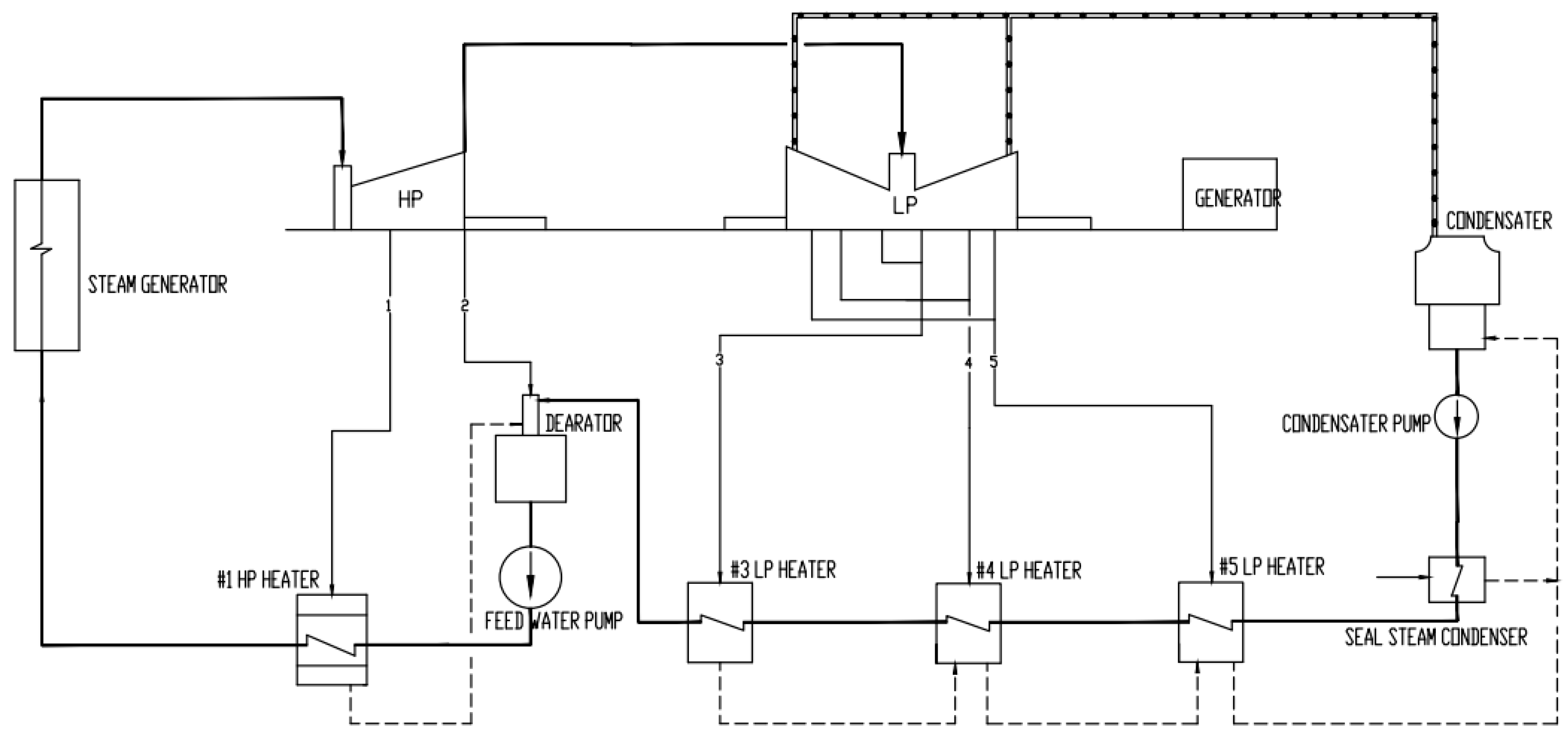
  • This study selected the 210 MWe High-Temperature Gas-Cooled Reactor Pebble-Bed Module (HTR-PM) as the reactor technology for the retrofit of a typical 300 MW class subcritical coal-fired unit and analyzed the conversion strategy for the conventional island. The results show the following:
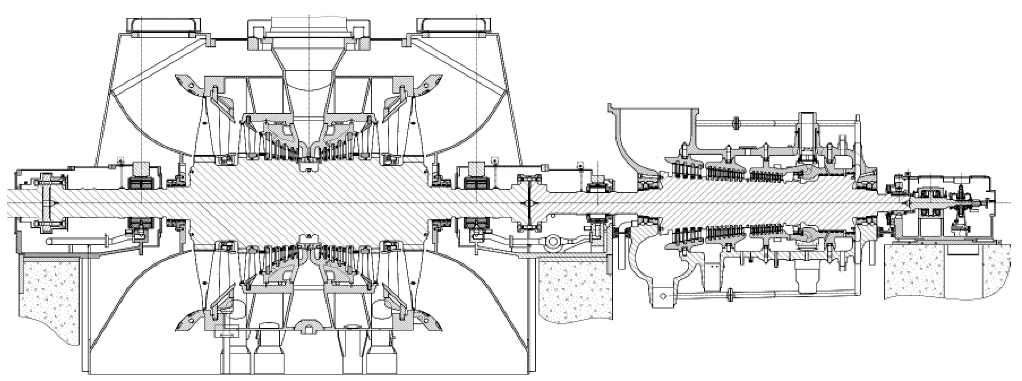
    • The HTR-PM turbine, with a capacity of 210 MWe, is optimized based on the mature thermal turbine high-pressure and low-pressure modules and the main steam valve module. It shares many common features and a high degree of inheritance with the coal-fired power 300 MW sub-critical turbine. The retrofit strategy for the turbine is to carry out through-flow modification and high-temperature component material upgrading under the premise of keeping the original bearing seat span and base unchanged.
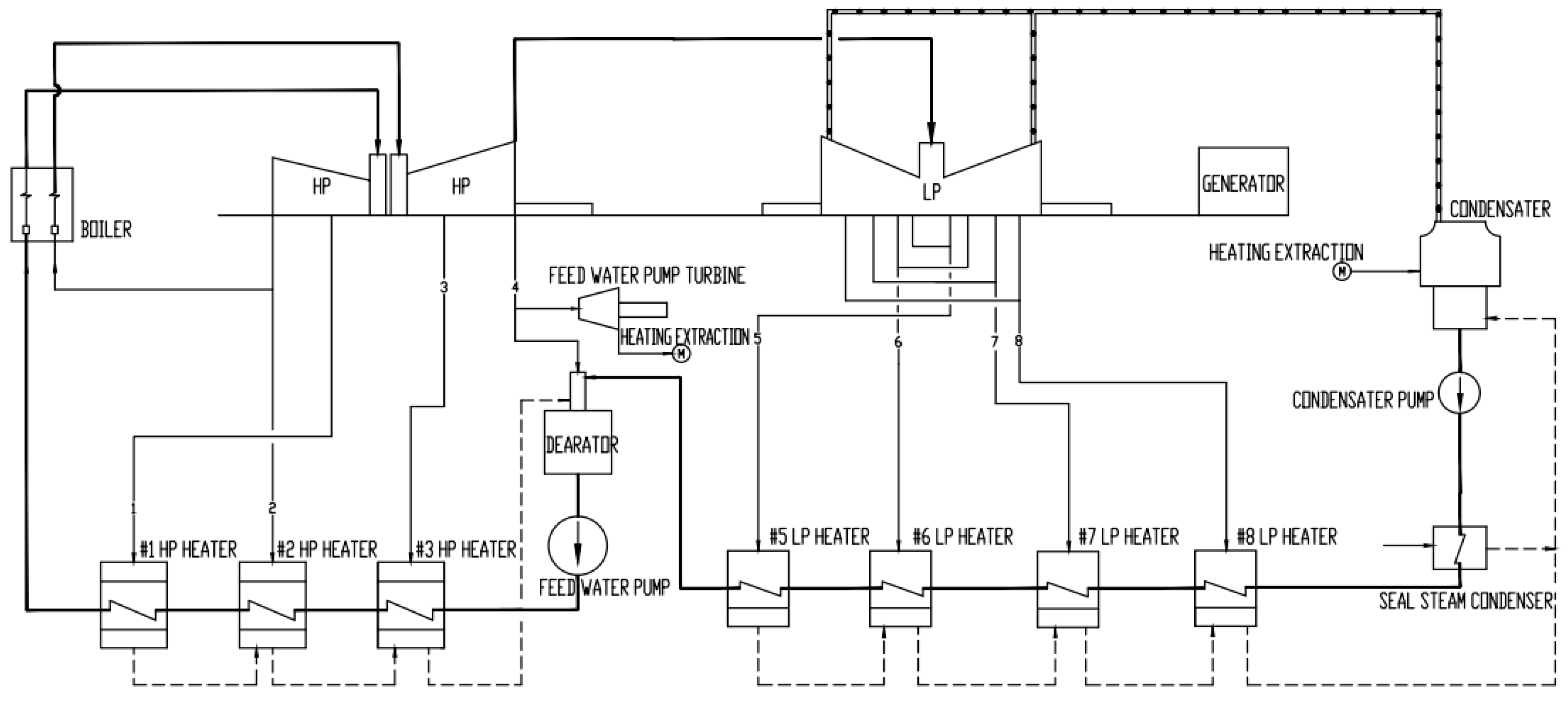
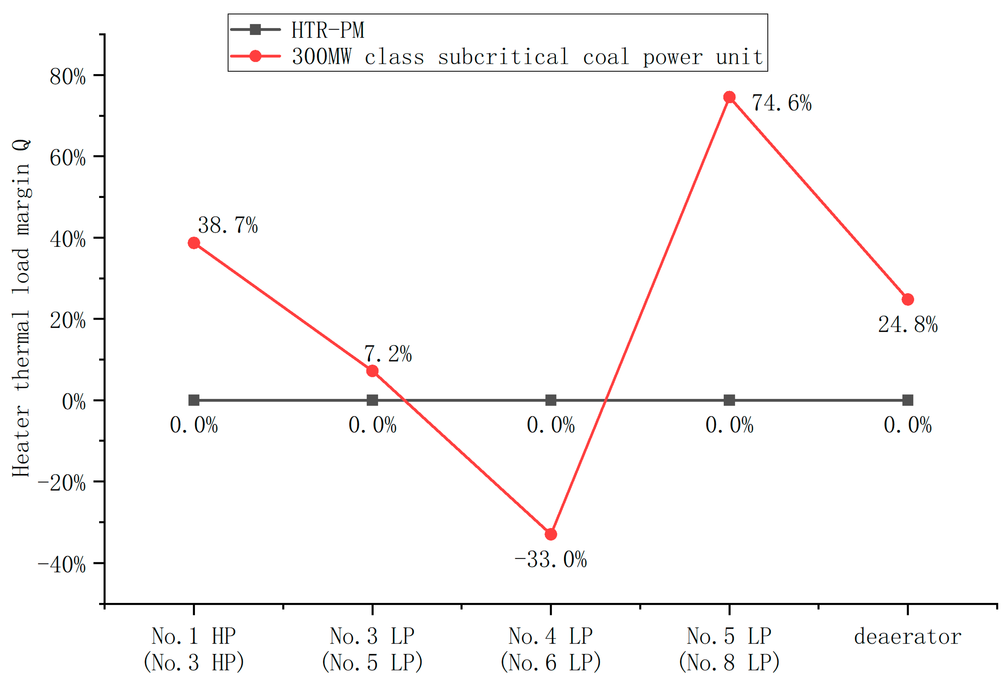
    • The No. 3 HP heater and the No. 5, No. 6, and No. 8 LP heaters of the 300 MW class subcritical coal-fired unit have similar parameters to the No. 1 HP heater and the No. 3, No. 4, and No. 5 LP heaters of the HTR-PM unit, respectively, and they can be used as the corresponding heaters for retrofitting. The heater of the coal power unit has sufficient structural strength to meet the required pressure-temperature requirements after the retrofit. The materials used for the shells, tube bundles, and tube sheets of both types of units are essentially identical, and no material upgrades are necessary. The heat load of the No. 6 low-pressure heater is insufficient to require capacity expansion and reconstruction, while the existing capacity of other high and low-pressure heaters, deaerator, and condenser can meet the heat load requirement after retrofit.
    • The configuration, as well as the flow rate and head of feed water pump, condensate pump, and open- and closed-cycle cooling pumps of 300 MW class subcritical coal-fired unit can basically meet the requirements of HTR-PM unit. The modification strategy is to optimize the impeller or number of stages of the existing pumps according to the specific parameter requirements in order to improve the operating efficiency of the pumps at rated operating conditions. In terms of response speed and feed water supply stability after turbine trip, the electric feed water pump is superior to the turbine-driven pump for the pump drive method. The operational reliability of the turbine-driven pump configuration scheme for the HTR-PM unit requires further study.
    • The wall thickness and flow velocity of the main thermal system pipes for the 300 MW subcritical coal-fired unit basically meet the requirements of the system parameters for the HTR-PM unit. The main steam piping, steam extraction piping, and open and closed circulating water piping of both types of units are made of the same or similar materials and do not need to be upgraded when retrofitting. For high-pressure feed water and condensate piping, the adaptability of materials for retrofitting should be based on the “Cr” content of the original piping material, considering the effects of flow accelerated corrosion.
    • For the HTR-PM unit, each reactor is equipped with a set of start-up/shutdown systems with about 35% capacity. When converting coal power to nuclear, a start-up/shutdown system must be added separately, as conventional coal units are not equipped with them. The start-up/shutdown system is situated in the conventional island plant. When retrofitting, the available space in the main plant can be utilized or a span can be added to the turbine’s head side to arrange the equipment and piping of the start-up/shutdown system.
This paper concludes with an explanation of why HTGRs were selected for this study in preference to other advanced reactors that could provide high-temperature heat, such as the fluoride salt-cooled, high-temperature reactor (FHR) and gas-cooled fast reactor (GFR). This is due to the accumulation of considerable experience in the field of construction of HTGR research and prototype reactors. An overview of past HTGR plants and projects as of 2018 is provided in Figure 9. Five countries: Great Britain, the U.S., Germany, Japan, and China have experience with operating and thus licensing HTGRs [46]. The UK operated the first HTGR research reactor called DRAGON from 1963 to 1976. The U.S. and Germany are the countries that operated research (PB-1 and AVR) as well as prototype (FSR and THTR) HTGRs. China has joined this group since the prototype HTR-PM has been operational.
HTR-PM nuclear power units are designed to be immune to core meltdowns, to meet the most stringent international nuclear safety standards, to satisfy the most stringent radiation dose limitations for the site perimeter under accident conditions, and to have an inherent safety profile that maximizes public acceptance of nuclear energy. This maximizes public acceptance of nuclear energy. The high-temperature characteristics of HTR-PM permit its integration with the steam cycle in the reactor’s second loop, enabling the generation of subcritical, supercritical, and ultra-supercritical power. Additionally, the HTR-PM is capable of achieving cogeneration through the extraction of steam from the turbine, thereby providing industrial and civil heating steam with distinct parameters ranging from 100 to 400 °C. The features above permit the utilization of HTR-PM units to replace coal-fired power units with equivalent power, thereby facilitating the efficient generation of power.
In the context of China’s current national conditions, the high-temperature gas-cooled reactor is positioned as a supplementary technology to pressurized water reactor nuclear power, with the objective of becoming the primary source of nuclear energy for heat supply [47]. The 600,000 kilowatt-class nuclear power unit under development (HTR-PM600) is intended to utilize the technology already proven in the demonstration project and to meet the market demand for larger capacity by combining multiple modules while maintaining the main equipment and systems in their original configuration. It is possible to maintain a limited degree of economic disparity between this unit and commercial Generation 3 pressurized water reactor (PWR) nuclear power plants. Currently, China has initiated preliminary work on the HTR-PM600 project in several provinces and cities, including Zhejiang, Guangdong, Fujian, and Jiangxi [48]. This provides a solid foundation for the demonstration project of modular high-temperature gas-cooled reactor units, which will replace coal power.

Author Contributions

Conceptualization, B.L. and L.Z.; methodology, X.Z. and W.L.; validation, W.L., X.Z. and Y.S.; formal analysis, X.Z. and W.L.; investigation, B.L., L.Z., X.Z. and W.L.; data curation, X.Z. and Y.S.; writing—original draft preparation, X.Z.; writing—review and editing, B.L., L.Z., W.L., X.Z., Y.Y. and Y.S.; project administration, W.L.; funding acquisition, Y.Y. All authors have read and agreed to the published version of the manuscript.

Funding

This research received no external funding.

Data Availability Statement

The data presented in this study are available on request from the corresponding author.

Conflicts of Interest

Authors Bixiong Luo, Li Zhang, Wei Li, Xinwei Zhu, Yongjian Ye, and Yanlin Su were employed by the company China Power Engineering Consulting Group Co., Ltd. All authors declare research was conducted in the absence of any commercial or financial relationships that could be construed as a potential conflict of interest.

References

  1. Xin, B.A.; Chen, M.; Zhao, P.; Sun, H.D.; Zhou, Q.Y.; Qin, X.H. Research on Coal Power Generation Reduction Path Considering Power Supply Adequacy Constraints Under Carbon Neutrality Target in China. Proc. CSEE 2022, 42, 6919–6931. [Google Scholar] [CrossRef]
  2. Wang, S.T.; Yang, X.G.; Chang, J.W. Research on status of service life of coal-fired units at home and abroad. Therm. Power Gener. 2020, 49, 11–16. [Google Scholar] [CrossRef]
  3. From Coal to Nuclear: A Practical Guide for Developing Nuclear Energy Facilities in Coal Plant Communities; EPRI: Palo Alto, CA, USA, 2023; p. 3002026517.
  4. Cothron, E.; Greenwald, J. Resources for Coal Repowering with Nuclear Energy; Nuclear Innovation Alliance: Washington, DC, USA, 2023. [Google Scholar]
  5. Hansen, J.; Jenson, W.; Wrobel, A.; Stauff, N.; Biegel, K.; Kim, T.; Belles, R.; Omitaomu, F. Investigating Benefits and Challenges of Converting Retiring Coal Plants into Nuclear Plants; INL/RPT-22-67964-Rev000, 1886660; Idaho National Laboratory (INL): Idaho Falls, ID, USA, 2022. [Google Scholar]
  6. Qvist, S.; Gładysz, P.; Bartela, Ł.; Sowiżdżał, A. Retrofit Decarbonization of Coal Power Plants—A Case Study for Poland. Energies 2021, 14, 120. [Google Scholar] [CrossRef]
  7. Bartela, Ł.; Gładysz, P.; Andreades, C.; Qvist, S.; Zdeb, J. Techno-Economic Assessment of Coal-Fired Power Unit Decarbonization Retrofit with KP-FHR Small Modular Reactors. Energies 2021, 14, 2557. [Google Scholar] [CrossRef]
  8. Bartela, Ł.; Gładysz, P.; Ochmann, J.; Qvist, S.; Sancho, L.M. Repowering a Coal Power Unit with Small Modular Reactors and Thermal Energy Storage. Energies 2022, 15, 5830. [Google Scholar] [CrossRef]
  9. Haneklaus, N.; Qvist, S.; Gładysz, P.; Bartela, Ł. Why Coal-Fired Power Plants Should Get Nuclear-Ready. Energy 2023, 280, 128169. [Google Scholar] [CrossRef]
  10. Xu, S.; Lu, Y.H.M.; Mutailipu, M.; Yan, K.; Zhang, Y.L.; Qvist, S. Repowering Coal Power in China by Nuclear Energy—Implementation Strategy and Potential. Energies 2022, 15, 1072. [Google Scholar] [CrossRef]
  11. Zhang, Z.Y.; Dong, Y.J.; Shi, Q.; Li, F.; Wang, H.T. 600-MWe High-Temperature Gas-Cooled Reactor Nuclear Power Plant HTR-PM600. Nucl. Sci. Tech. 2022, 33, 8. [Google Scholar] [CrossRef]
  12. Fan, Q.W.; Guan, H.J.; Chen, X.H.; Liu, J. Present Situation and Key Problem Analysis in Parameters Increasing Reformation Technology for Active Coal-fired Thermal Power Units. J. Eng. Therm. Energy Power 2022, 37, 12–18, 39. [Google Scholar] [CrossRef]
  13. Tang, J.M. The First Domestic 600MW Coal-Fired Unit High Efficient Comprehensive Upgrading of Critical Technology Application. In Proceedings of the 2016 Annual Meeting of the Clean and Efficient Power Generation Technology Collaborative Network, Nanjing, China, 15–18 November 2016. [Google Scholar]
  14. Fan, Y.T.; Li, F. Discussion on Energy-Saving Modification of 300MW Unit with High-Efficiency Subcritical Parameter Upgrading. In Proceedings of the Fifth Symposium on New Technologies for Cogeneration and Deep Energy Saving in Coal Power, Nanjing, China, 16–18 May 2016; p. 9. [Google Scholar]
  15. Bai, D.L.; Zhang, J.S.; Xie, G.Y.; Xing, J.W. Study on Energy-saving Emission Reduction Transformation Feasibility of Daihai Power Plant Two Unit. Boil. Technol. 2017, 48, 60–62. [Google Scholar]
  16. Zhang, P.; Cong, Y.L. Improve 600 MW Sub-critical Steam Turbine Steam Temperature Impact Assessment of the Efficiency of the Unit. Energy Conserv. Technol. 2018, 36, 79–83. [Google Scholar]
  17. Chang, Z.; Zhang, Z.H.; Zhao, W.B.; Wan, K.F.; Gao, Z.B. Upgrade Scheme Comparison Between Parameter-increase and Cross-Generation for Subcritical Units. Power Gener. Technol. 2017, 38, 21–24. [Google Scholar]
  18. Min, Y.; Chen, D.L. Study on the Thermodynamic Property of Supercritical Reform for 300MW Subcritical Coal-fired Boiler. China Electr. PowerTechnology Ed. 2016, 3, 51–55. [Google Scholar]
  19. Cui, C.T.; Zhao, Y.Z.; Yan, C.W. Parameter Optimization Design of Regenerative Extraction Steam at Parameter Rising of Subcritical Unit. J. Eng. Therm. Energy Power 2017, 32, 115–118, 128. [Google Scholar] [CrossRef]
  20. Shi, J.Y.; Qi, L.; Yang, Y.; Wang, Y.; Deng, Z.C.; Shan, X.F.; Xu, M.J. Analysis and Study on the Adaptability of the Secondary Circuit for the Optimization and Upgrading of the 320MW Nuclear Power Turbine-Generator Unit. China Nucl. Power 2021, 14, 465–470. [Google Scholar]
  21. DL/T 5054-2016; Code for design of steam/water piping of fossil-fired power plant. Beijing China Planning Publishing House: Beijing, China, 2016.
  22. Zhang, Z.; Dong, Y.; Li, F.; Zhang, Z.; Wang, H.; Huang, X.; Li, H.; Liu, B.; Wu, X.; Wang, H.; et al. The Shandong Shidao Bay 200 MWe High-Temperature Gas-Cooled Reactor Pebble-Bed Module (HTR-PM) Demonstration Power Plant: An Engineering and Technological Innovation. Engineering 2016, 2, 112–118. [Google Scholar] [CrossRef]
  23. Li, Y.; Liu, X.S.; Gu, M.M.; He, X.Z. Structure Characteristics of 210 MW Nuclear Steam Turbine with High Temperature Gas-Cooled Reactor. Therm. Turbine 2021, 50, 187–191. [Google Scholar] [CrossRef]
  24. Shi, J.Y.; Yang, H.; Zhang, H.T.; Fang, Y.; Li, J.; Wang, B.L. New Progress and Development Direction of Steam Turbines in China. J. Chin. Soc. Power Eng. 2021, 41, 542–550. [Google Scholar] [CrossRef]
  25. Xiu, D.M. Features and Type Selection of Steam Turbines in Nuclear Power Plants. J. Eng. Therm. Energy Power 2010, 25, 459–462, 472. [Google Scholar]
  26. Yang, X.H.; Shan, S.C. Analysis for Major Problem of Nuclear Turbine Proposal. Turbine Technol. 2007, 49, 5–7. [Google Scholar]
  27. Huang, R. Analysis of Material Selection and Nationalization of National Super-critical Steam Turbine Unit. Turbine Technol. 2001, 43, 9–13, 23. [Google Scholar]
  28. Lu, Z.Q.; Han, W.J. Material Selection Characteristics of 24.2 MPa-566 °C/566 °C Supercritical Steam Turbine. Turbine Technol. 2004, 46, 164–166. [Google Scholar]
  29. Zhu, Z.J. Design and Research of Inlet Valve for Steam Turbine in 200mw High Temperature Gas Cooled Reactor Nuclear Power Plant. Master’s Thesis, Shanghai Jiao Tong University, Shanghai, China, 2012. [Google Scholar]
  30. Dong, L.Y.; Zhou, Z.W. Simulation Study on The Condensing System of High-Temperature Reactor Demonstration Power Station HTR-PM200 Based on Vpower. J. Shenyang Inst. Eng. Sci. 2011, 7, 16–19. [Google Scholar] [CrossRef]
  31. Liu, J.F.; Wang, C.L. Simulation Modeling of High Temperature Gas Cooled Reactor Steam Turbine Based on MATLAB/Simulink. Turbine Technol. 2022, 64, 408–412. [Google Scholar]
  32. Dong, L.Y.; Zhou, Z.W.; Zhou, Y.P.; Sui, Z.; Zhou, S.Y.; Li, F. Study on Graphical Modeling and Simulation of Secondary Loop in HTR-PM. Nucl. Power Eng. 2012, 33, 138–142. [Google Scholar]
  33. Zhang, R.X.; Wang, B.X.; Zhao, F.; Peng, W.C.; Chang, C.X.; Shi, J.; Ye, L.; Li, K. Cleaning schemes for the secondary circuit in high temperature gas-cooled reactors. Therm. Power Gener. 2017, 46, 130–135, 140. [Google Scholar]
  34. Liu, F.; Liu, Y.B.; Yao, H.M.; Sun, Y.P.; Yao, J.T.; Long, G.J.; Zhao, F. Feasibility analysis for chemical cleaning of the secondary circuit in high temperature gas-cooled reactors using catalytic citric acid. Therm. Power Gener. 2019, 48, 79–83. [Google Scholar] [CrossRef]
  35. Liu, R.M. Design of 200MW Unit Horizontal High Pressure Feedwater Heater with Dsz Dcz and Cz Inside. Boil. Manuf. 2012, 6, 49–51. [Google Scholar]
  36. Tang, Y.; Yuan, B. Scheme Study on Single/Double Row High-Pressure Heaters of 1000MW Power Unit with Secondary Reheat Cycles. Mech. Manag. Dev. 2019, 34, 160–161, 171. [Google Scholar] [CrossRef]
  37. Sun, H.C.; Hou, X.J.; Zhang, Y.; Li, R.P.; Xing, W.B. A Design Scheme for the Feedwater and Control System of the Multi-Module HTGR. China Nucl. Power 2023, 16, 573–582. [Google Scholar]
  38. Yu, L. Research on DaLaTe Power Plant 330MW Unit Water Pump Reform. Master’s Thesis, North China Electric Power University, Beijing, China, 2019. [Google Scholar]
  39. Qian, H.W. HTR-PM600 Conventional Island Feed Water System Configuration Research. Energy Res. Manag. 2017, 1, 40–42, 53. [Google Scholar] [CrossRef]
  40. GB 50660-2011; Code for design of fossil fired power plant. Beijing China Planning Publishing House: Beijing, China, 2011.
  41. Lu, W.K.; Wu, Z.; Qiu, Z.Z. Development of a New Electrode Type for WB36CN1 (HD15Ni1MnMoNbCu) Steel in Nuclear Power Plants. In Proceedings of the Fourth Forum of the Collaborative Network on Steel and Welding Technologies for Ultra (Supercritical) Critical Boilers, Nanjing, China, 15–17 November 2011; pp. 207–214. [Google Scholar]
  42. Guo, Y.R.; Wu, H.; Hu, M.H.; Hu, B. R&D of WB36CN1 Seamless Steel Pipe Used for Steam/Water Supply Piping Circuit of Conventional Island of Nuclear Power Plant. Steel Pipe 2010, 39, 31–35. [Google Scholar]
  43. Qian, Q.Y.; Qian, H.W.; Huang, X.J. Design and research of steam-water separator system for high temperature high temperature reactor-pebbled modules. Therm. Power Gener. 2015, 44, 103–106, 112. [Google Scholar]
  44. Cai, B.L.; Qian, Q.Y. Dynamic process characteristics analysis about startup/shutdown system of high temperature gas cooled reactor and verification of control strategy. Therm. Power Gener. 2015, 44, 62–68. [Google Scholar]
  45. Liu, J.F.; Ma, X.L.; Han, C.G.; Dong, L. The Optimization for Bypass Control Mode in Start-up and Shutdown System of HTR-PM. Turbine Technol. 2019, 61, 413–416, 464. [Google Scholar]
  46. Reitsma, F.; Woods, P.; Fairclough, M.; Kim, Y.; Tulsidas, H.; Lopez, L.; Zheng, Y.; Hussein, A.; Brinkmann, G.; Haneklaus, N.; et al. On the Sustainability and Progress of Energy Neutral Mineral Processing. Sustainability 2018, 10, 235. [Google Scholar] [CrossRef]
  47. Zhang, Z.Y.; Wu, Z.X.; Wang, D.Z.; Tongj, J. Development Strategy of High Temperature Gas Cooled Reactor in China. Strateg. Study CAE 2019, 21, 12–19. [Google Scholar] [CrossRef]
  48. Lei, M.Z. Commercialisation and Application Prospect of HTR. China Nucl. Power 2018, 11, 26–29. [Google Scholar]
Figure 1. Reactor matching methodology for nuclear power retrofit of coal-fired power plants.
Energies 17 02912 g001
Figure 2. Thermal system flowchart of a 210 MW HTR-PM unit.
Energies 17 02912 g002
Figure 3. Thermal system flowchart of a typical 300 MW class subcritical coal-fired unit.
Energies 17 02912 g003
Figure 4. Research methodology for conventional island retrofit strategy.
Energies 17 02912 g004
Figure 5. Overall longitudinal section of the turbine of a 210 MW HTR-PM unit [23].
Energies 17 02912 g005
Figure 6. Overall longitudinal section of the turbine of a typical 300 MW class subcritical coal-fired unit.
Energies 17 02912 g006
Figure 7. Arrangement of the main steam valve and control valves for steam turbine: (a) 210 MW HTR-PM unit [23]; (b) typical 300 MW class subcritical coal-fired unit.
Energies 17 02912 g007
Figure 8. Analysis results of heat load adaptability of the heat exchange equipment.
Energies 17 02912 g008
Figure 9. High-temperature gas-cooled reactor (HTGR) plants/projects by country as of 2018 [46].
Energies 17 02912 g009
Table 1. Table of the principal thermal parameters of pressurized water reactors.
Reactor TypeCPR1000VVER-1000AP1000EPR
Rated thermal power/MW2903299434144613
Turbine rated power/MW1050~11201070~11351200~13001700~1780
Rated main steam pressure/MPa6.435.885.387.46
Rated main steam temperature/°C280.1274.3268.5290.1
Rated main steam humidity/%0.470.500.450.49
Rated main steam flow rate/kg/s1613.41633.31888.62609.6
Table 2. Main technical parameters of the HTR-PM and HTR-PM600 nuclear power plants.
Reactor TypeHTR-PMHTR-PM600
Reactor module thermal power (MW)250250
Number of the reactor modules26
Plant thermal power (MW)5001500
Plant electricity generation power (MW)210670
Helium pressure (MPa)77
Helium temperature at reactor inlet/outlet (°C)250/750250/750
Fresh steam temperature (°C)566566
Fresh steam pressure (MPa)13.2413.24
Table 3. Comparison table of the main parameters of coal-fired power plants, high-temperature gas-cooled reactors, and pressurized water reactor nuclear power stations.
ParametersTargeted Coal-Fired Power Plants in the First PhaseHigh-Temperature Gas-Cooled Reactor (HTGR) Nuclear Power Plants [11,22,23]Pressurized Water Reactor (PWR) Nuclear Power Plants [24,25,26]
Single-unit capacityMostly 300 MWe/600 MWe classThe 210 MWe unit is currently in operation, while the 670 MWe unit is still under research and development.Mostly 1000 MWe and larger power plants
Typical steam admission parametersUltra-high pressure: 13.2 MPa/535 °C/535 °C
Subcritical: 16.7 MPa/538 °C/538 °C
Supercritical: 24.2 MPa/566 °C/566 °C
13.24 MPa/566 °C5.38–7.5 MPa/268–290 °C
Work medium characteristicsMostly superheated steam; only the last few stages of the low-pressure cylinder are wet steamMostly superheated steam; only the last few stages of the low-pressure cylinder are wet steam.Mostly wet steam; only the first few stages of the low-pressure cylinder are superheated steam
Turbine speed3000 r/min3000 r/minBelow 1000 MW class mostly 3000 r/min;
1500 r/min for 1000 MW class and above
Final bladeAs benchmarkSubstantially comparable to coal unitsLonger final blades should be used for half-speed units
Inlet and exhaust steam volumeAs benchmarkSubstantially comparable to coal unitsThe enthalpy drop is small; the mass flow rate is approximately twice that of a coal power plant, and the volume flow rate is about four to six times that of a coal power plant
Exhaust areaAs benchmarkSubstantially comparable to coal unitsAbout twice as much as coal units
Cylinder size and numberAs benchmarkSubstantially comparable to coal unitsCylinders are typically larger and heavier than those used in coal power plants; additionally, the number of low-pressure cylinders is greater
Rotor size and weightAs benchmarkSubstantially comparable to coal unitsThe unit features a longer shaft system and a larger rotor size and weight
Table 4. Comparison table between conventional island retrofit of coal-fired units to nuclear and retrofit of upgrading subcritical unit parameters.
ParametersConventional Island Retrofit of Coal-Fired Units to NuclearRetrofit of Upgrading Subcritical Unit Parameters [12,13,14,15,16,17]
Inlet steam temperature Increase from 538 °C to 566 °CIncrease from 538 °C to 566 °C
Inlet steam pressure Reduced from 16.7 MPa to 13.24 MPaRemain unchanged
Steam turbine Conventional through-flow modifications are required, and high-temperature components need to be accounted for with or without material upgradesConventional through-flow modifications are required; high-temperature components require material upgrades
BoilerBoiler removal and construction of a new nuclear islandUpgrades required
Reheat systemChange from single reheat to no reheatKeep the single reheat unchanged
Regenerative systemRegenerative system numbers from an eight-stage to a five-stageRemain regenerative system numbers unchanged
Main auxiliary equipment and system pipelinesThe capacity, strength, and material of equipment and piping need to be checkedThe capacity, strength, and material of equipment and piping need to be checked
Table 5. Comparative table of the main technical parameters of the steam turbine.
ParametersTurbine of 210 MW HTR-PM Unit [23]Turbine of a Typical 300 MW Class Subcritical Coal-Fired Unit
TypeSingle shaft, two cylinder, two turbine exhaust, condensing steam turbineSingle shaft, single reheat, two cylinder, two turbine exhaust, condensing steam turbine
Rated power/MW 211.9300
Steam pressure in front of main valve/MPa 13.2416.70
Steam temperature in front of main valve/°C 566538
Main steam rated flow/(t/h) 691.29965.82
Inlet pressure of low-pressure cylinder/MPa0.77320.863
Inlet temperature of low-pressure cylinder/°C 200.98342.8
Exhaust flow/(t/h) 2 × 2352 × 287
Rated back pressure/kPa4.54.9
Rated speed/(r/min) 30003000
Regenerative system1 high-pressure heater, 3 low-pressure heaters, and 1 deaerator3 high-pressure heaters, 4 low-pressure heaters, and 1 deaerator
Table 6. Comparative table of the structural characteristics of the steam turbine.
ParametersTurbine of 210 MW HTR-PM Unit [23]Turbine of a Typical 300 MW Class Subcritical Coal-Fired Unit
High-pressure cylinder1 high-pressure cylinder,
one-way flow,
double cylinder structure,
number of throughflow stages I + 20
1 high- and medium-pressure cylinder, reverse one-way flow in high- and medium-pressure cylinder,
double cylinder structure,
number of HP throughflow stages I + 14, number of MP throughflow stages I + 8
Low-pressure cylinder1 bidirectional flow LP cylinder,
double cylinder structure,
number of throughflow stages 2 × 7
1 bidirectional flow LP cylinder,
double cylinder structure,
number of throughflow stages 2 × 7
Forms of supports and bearingsDouble bearing support;
a total of three bearing housings
Double bearing support;
a total of three bearing housings.
Low pressure last stage blades height1050 mm1050 mm
Table 7. Comparison table of thermal parameters of high- and low-pressure heaters and deaerator.
Typical 300 MW class subcritical coal-fired unit No. 3 HP HeaterNo. 5 LP HeaterNo. 6 LP HeaterNo. 8 LP HeaterDeaerator
Steam flow rate (kg/h)43,63242,40027,82729,67343,987
Steam pressure (MPa)1.8760.3710.1280.0230.880
Steam temperature (°C)450.5241.1133.263.1343.6
Water-side flow rate (kg/h)965,824734,033734,033734,033734,033
210 MW HTR-PM unit [31,32] No. 1 HP heaterNo. 3 LP heaterNo. 4 LP heaterNo. 5 LP heaterDeaerator
Steam flow rate (kg/h)43,03146,86740,58212,97540,434
Steam pressure (MPa)1.73360.33570.09010.01540.789
Steam temperature (°C)287.6137.696.754.5201.9
Water-side flow rate (kg/h)671,290587,994587,994587,994587,994
Table 8. Comparison table of materials of high- and low-pressure heaters and deaerator.
Typical 300 MW class subcritical coal-fired unit No. 3 HP HeaterNo. 5 LP HeaterNo. 6 LP HeaterNo. 8 LP HeaterDeaerator
Shell material SA516Gr70Q245RQ245RQ245RQ345R
Tube bundle material SA556GrC2SA688-TP304SA688-TP304SA688-TP304--
Tube sheet material 20MnMoP355GHP355GH20MnMo--
TypeHorizontal;
u-tube
Horizontal;
u-tube
Horizontal;
u-tube
Horizontal;
u-tube
Horizontal;
built-in
210 MW HTR-PM unit [33,34] No. 1 HP heaterNo. 3 LP heaterNo. 4 LP heaterNo. 5 LP heaterDeaerator
Shell material Q245RQ245RQ245RQ245RQ345R
Tube bundle material SA556GrC2SA688-TP304SA688-TP304SA688-TP304--
Tube sheet material 20MnMo20MnMo20MnMo20MnMo--
TypeVertical;
u-tube
Vertical;
u-tube
Horizontal;
u-tube
Horizontal;
u-tube
Horizontal;
built-in
Table 9. Comparison table of condenser parameters.
Tube-Side/Shell-Side Design Pressure
(MPa)
Back Pressure (KPa)Exhaust Flow Rate (t/h)Circulating Water Flow Rate (t/h)Cooling Surface Area (m2)Full Water Weight
(t)
210 MW HTR-PM unit [23,30]0.4/0.0984.547027,71112,0001200
Typical 300 MW class subcritical coal-fired unit0.45/0.0984.957438,00021,5001300
Table 10. Comparison table for feed water pump configurations.
Operation ModeNumber and CapacityDrive ModeFlow Rate (m3/h)Pump Head (m)
210 MW HTR-PM unittwo operations and one standby3 × 50%electric3741960
Typical 300 MW class subcritical coal-fired unitNO. 1 schemetwo operations and one standby2 × 50%turbine-driven6062375
1 × 30%electric3832373
NO. 2 schemetwo operations and one standby3 × 50%electric6202510
Table 11. Comparison table for condensate pump and open- and closed-cycle cooling pump configurations.
Operation ModeNumber and CapacityDrive ModeFlow Rate (m3/h)Pump Head (m)
210 MW HTR-PM unitcondensate pumptwo operations and one standby3 × 50%electric333238
closed cycle cooling pumpone operation and one standby2 × 100%electric79044
open cycle cooling pumpone operation and one standby2 × 100%electric170024
Typical 300 MW class subcritical coal-fired unitcondensate pumpone operation and one standby2 × 100%electric760326
closed cycle cooling pumpone operation and one standby2 × 100%electric80040
open cycle cooling pumpone operation and one standby2 × 100%electric190024
Table 12. Table of results of piping adaptability analysis.
Pipe NameOriginal Pipe Specification (mm)Pipe Minimum Adopted Wall Thickness (mm) *Actual Pipe Flow Velocity (m/s)Recommended Pipe Flow Velocity (m/s) *Original Pipe MaterialHTR-PM Unit Pipe Material [34]
Main steam mother pipeID368.3 × 4037.048.6540~60A335 P91A335 P91
Main steam branch pipeID273.05 × 3027.544.2640~60A335 P91A335 P91
High pressure feed water pipeOD355.6 × 2822.43.132~615NiCuMoNb5-6-4P265GH
Condensate pipeOD325 × 106.42.402~3.520HD245Cr
Third-stage (first-stage) steam extraction pipeOD273 × 103.333.7935~6012Cr1MoVG20
Fourth-stage (second-stage) steam extraction pipeOD325 × 7.52.939.5735~602020
Fifth-stage (third-stage) extraction pipeOD457 × 93.246.8930~502020
Open circulating water pipe
(pump inlet)
OD720 × 114.91.240.5~1.5Q235-A (plastic lining)Q235-A (plastic lining)
Open circulating water pipe
(pump outlet)
OD529 × 84.82.301.5~3.0Q235-A (plastic lining)Q235-A (plastic lining)
Closed circulating water pipe
(pump inlet)
OD457 × 75.01.430.5~1.5Q235-A20
Closed circulating water pipe
(pump outlet)
OD377 × 74.22.141.5~3.0Q235-A20
* The formula for pipe wall thickness, permissible stress of the material, and recommended flow rate in the table are sourced from the Code for design of steam/water piping of fossil-fired power plant (DL/T 5054-2016) [21].
Disclaimer/Publisher’s Note: The statements, opinions and data contained in all publications are solely those of the individual author(s) and contributor(s) and not of MDPI and/or the editor(s). MDPI and/or the editor(s) disclaim responsibility for any injury to people or property resulting from any ideas, methods, instructions or products referred to in the content.

