


A Review of Control Techniques for Inverter-Based Distributed Energy Resources Applications


Abstract
:1. Introduction
2. Different Topology of DERs
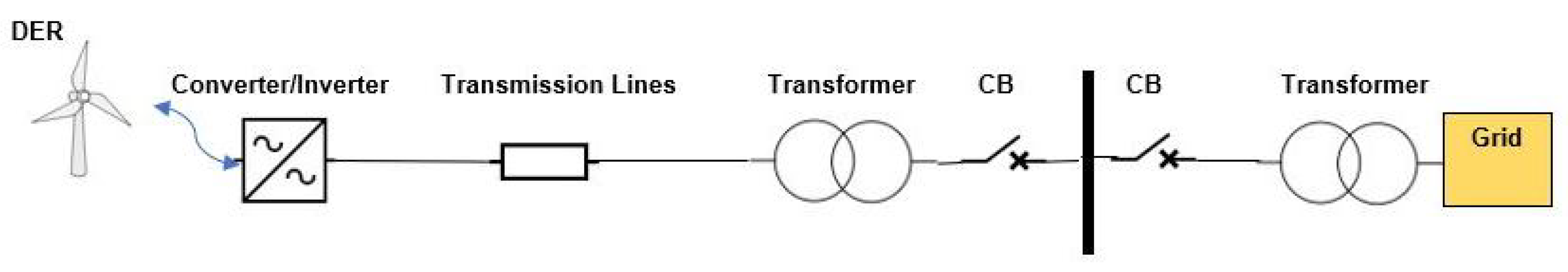
2.1. Grid-Connected Mode
2.2. Islanded Mode
2.3. Microgrid Mode
3. Different Types of Control Strategies
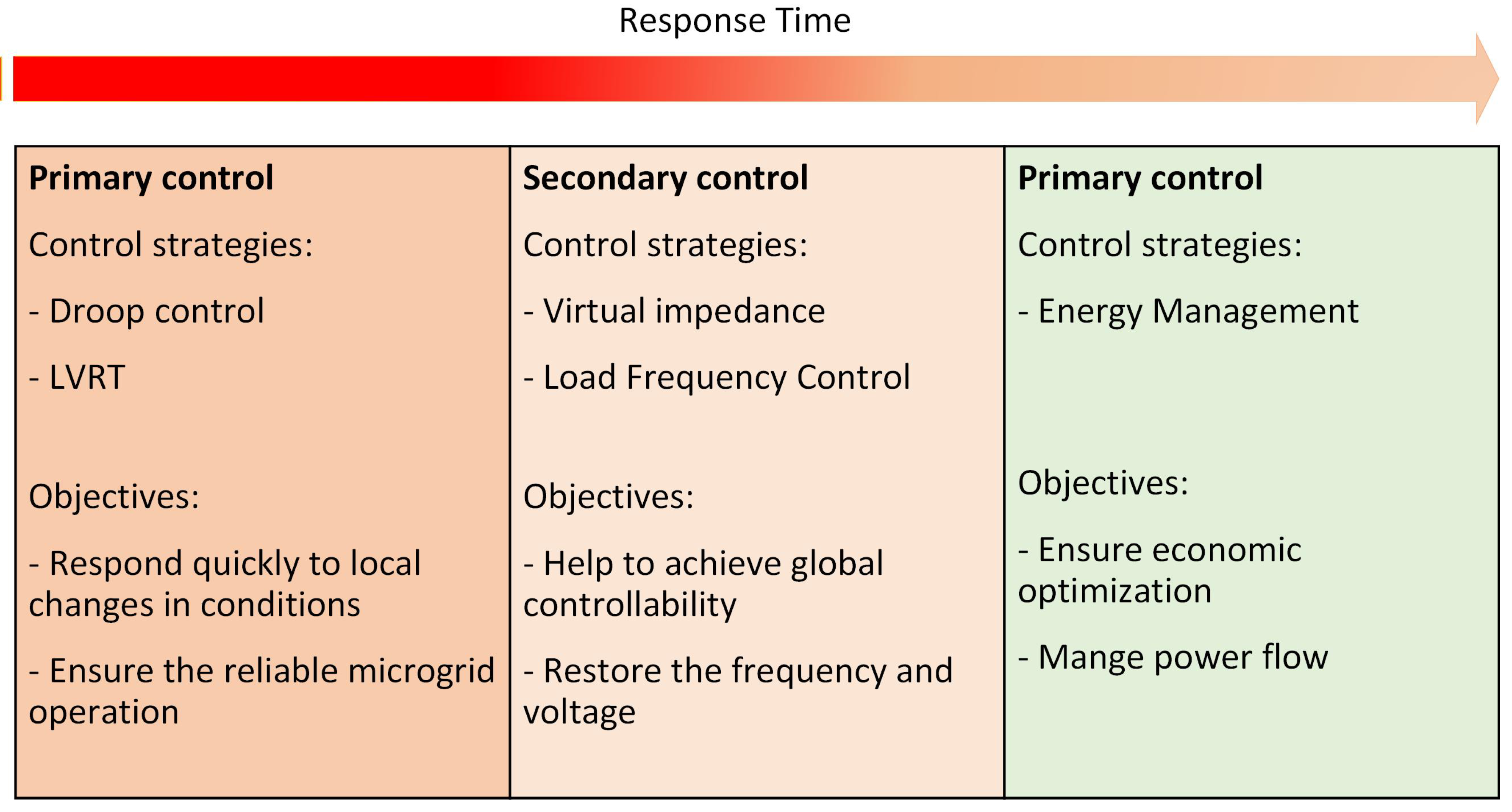
3.1. Primary Control Strategies
3.2. Secondary Control Strategies
3.3. Tertiary Control
4. Primary Control
4.1. Droop Control (without Communication Methods)
4.1.1. Power–Frequency (P/f) Droop
4.1.2. Power–Voltage (P/V) Droop
4.1.3. Frequency-Based Signal Injection
4.1.4. Voltage-Based Droop (VBD)
4.1.5. Virtual Flux Droop
4.1.6. Voltage–Current (V/I) Droop
4.1.7. Reactive Power Droop Control
4.1.8. Voltage and Frequency Droop Control
4.1.9. Application of Droop Control Strategy in BESSs
4.2. Low-Voltage Ride-Through Capability
4.2.1. Grid Code Requirement
4.2.2. LVRT Methods for Grid-Connected Wind Farms

| Methods | Feature | Ref. |
|---|---|---|
| Crow bar | A series of resistors in parallel between the rotor windings and the AC side of the rotor side; it is activated during overcurrent in the rotor or overvoltage in the DC link. | [64,74] |
| DC chopper | It consists of a resistor, IGBT, and diode arranged in parallel with a DC link capacitor. It is positioned between the RSC and GSC. During a grid fault, the IGBT is activated while braking resistors are employed to regulate the DC link voltage. | [66] |
| Energy storage system | It can smooth power output and contribute to maintaining grid frequency. | [67] |
| Series dynamic resistor (SDR) | It uses a dynamic resistor and a switch, which is placed in series between the rotor windings and the rotor-side converter (RSC). The switch is closed during normal operation and is open during a fault to activate the series resistor between the RSC and rotor windings to regulate rotor overcurrent. | [68] |
| Series Dynamic Braking Resistor (SDBR) | It stabilizes active power during fault conditions. It consists of a resistor that runs parallel with a switch. It is inserted when a fault occurs to prevent destabilization of the system. | [69] |
| Fault current limiter | The FCL can inject resistance into a stator circuit and regulate voltage during a fault. | [70] |
| FACT devices | It includes two methods: the Static Var Compensator (SVC) and the Static Synchronous Compensator (STATCOM). These methods contribute to voltage regulation by injecting or absorbing reactive power, enhancing overall system stability. | [71,72] |
4.2.3. LVRT Methods for Grid-Connected PVs
5. Secondary Control
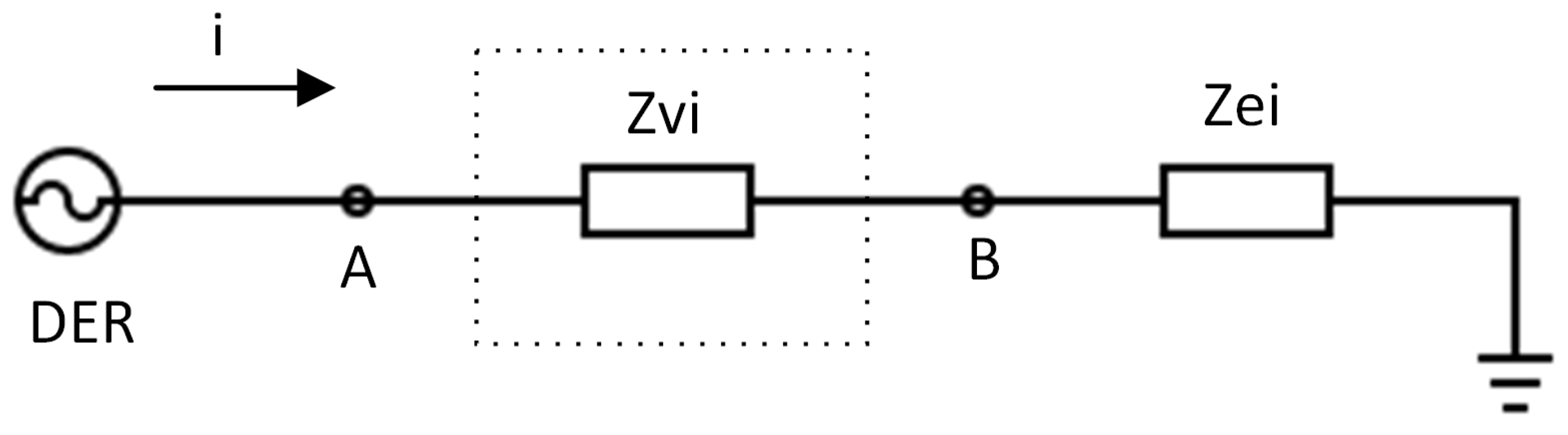
5.1. Virtual Impedance
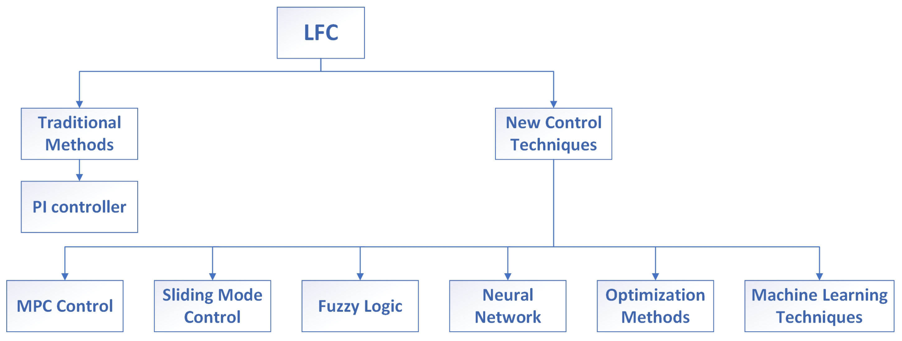
5.2. Load Frequency Control
5.2.1. Model Predictive Control (MPC)
5.2.2. Sliding Mode Control
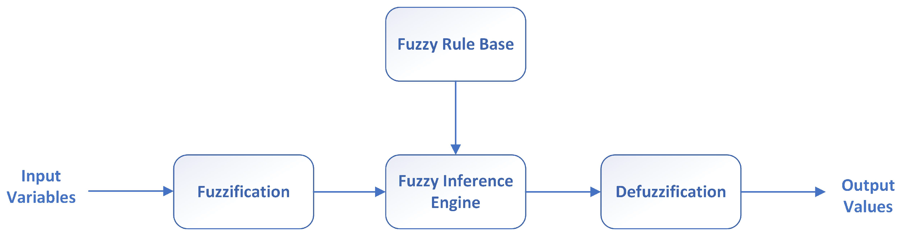
5.2.3. Fuzzy Logic Control
5.2.4. Neural Network-Based Control Strategies
5.2.5. Optimization Methods
5.2.6. Machine Learning-Based Control Strategies
6. Future Work
6.1. Future Work for Primary Control
6.1.1. Droop Control
- -
- Robustness to variations in network parameters: Investigate and enhance the robustness of droop control mechanisms against variations in network parameters. Developing adaptive strategies will enable stability under diverse and dynamic conditions.
- -
- Adaptation to advanced grid architectures: Explore adapting traditional droop control to accommodate advanced grid architectures, such as smart or microgrids. This adaptation ensures stability and optimal power sharing in evolving energy landscapes.
6.1.2. LVRT Strategies
- -
- Real-time monitoring and diagnosis: Develop real-time monitoring and diagnosis tools during LVRT events. Utilize cutting-edge sensors and communication technologies to provide precise, timely information on voltage fluctuations, enabling proactive reactions.
- -
- Hybrid control methods: Explore hybrid control methods that combine control system strategies with hardware modifications. This approach can effectively address extreme voltage dip situations, reduce system complexity, and mitigate the associated costs. In other words, For better LVRT performance, investigate combined strategies that include hardware adjustments and control system improvements. Examine the combination of adaptive control algorithms and upgraded hardware, like sophisticated protection devices, to enable successful LVRT in hybrid grids.
- -
- LVRT enhancement for hybrid grids: Examine and create adaptable LVRT plans for hybrid grids. To ensure strong performance under a range of operating conditions, these strategies should be able to adapt to fluctuations in power generation and system configurations dynamically.
6.2. Future Work for Secondary Control
6.2.1. Virtual Impedance
- -
- Sophisticated algorithms: Develop sophisticated virtual impedance algorithms that adapt to changing grid conditions. Investigate the application of artificial intelligence or machine learning to enhance the accuracy and flexibility of virtual impedance control.
6.2.2. Load Frequency Control (LFC)
- -
- Diagnostic and real-time monitoring technologies: Employ diagnostic and real-time monitoring technologies to manage load frequency effectively. Explore ways to improve situational awareness and provide timely information for frequency regulation, leveraging advanced sensors and communication technology.
7. Conclusions
Author Contributions
Funding
Data Availability Statement
Conflicts of Interest
Abbreviations
| DERs | Distributed Energy Resources |
| DC | direct current |
| AC | alternating current |
| PCC | Point of Common Coupling |
| P/f | power–frequency droop |
| P/V | power–voltage droop |
| VBD | voltage-based droop |
| V/I | voltage–current droop |
| BESS | battery energy storage system |
| PFC | primary frequency control |
| SOC | state-of-charge |
| PV | photovoltaic |
| ESS | energy storage system |
| DFIG | Doubly Fed Induction Generator |
| LVRT | low-voltage ride-through |
| RSC | rotor-side converter |
| GSC | grid-side converter |
| WECS | Wind Energy Conversion System |
| SDR | series dynamic resistor |
| SDBR | Series Dynamic Braking Resistor |
| FCL | fault current limiter |
| SVC | Static Var Compensator |
| SATATCOM | Static Synchronous Compensator |
| UPFC | Unified Power Flow Controller |
| WTs | wind turbines |
| HVDC | high-voltage direct current |
| RPI | reactive power injection |
| MPPT | Maximum Power Point Tracking |
| PI | proportional–integral controller |
| VSG | virtual synchronous generator |
| VI | virtual impedance |
| LFC | load frequency control |
| AGC | automatic generation control |
| ACE | area control error |
| MPC | model predictive control |
| AMPC | adaptive model predictive control |
| SMES | superconducting magnetic energy storage |
| SMC | sliding mode control |
| PSO | particle swarm optimization |
| FA | Firefly algorithm |
| DE | differential evolution |
| EA | Evolutionary Algorithm |
| RL | reinforcement learning |
| DQN | Deep Q-learning |
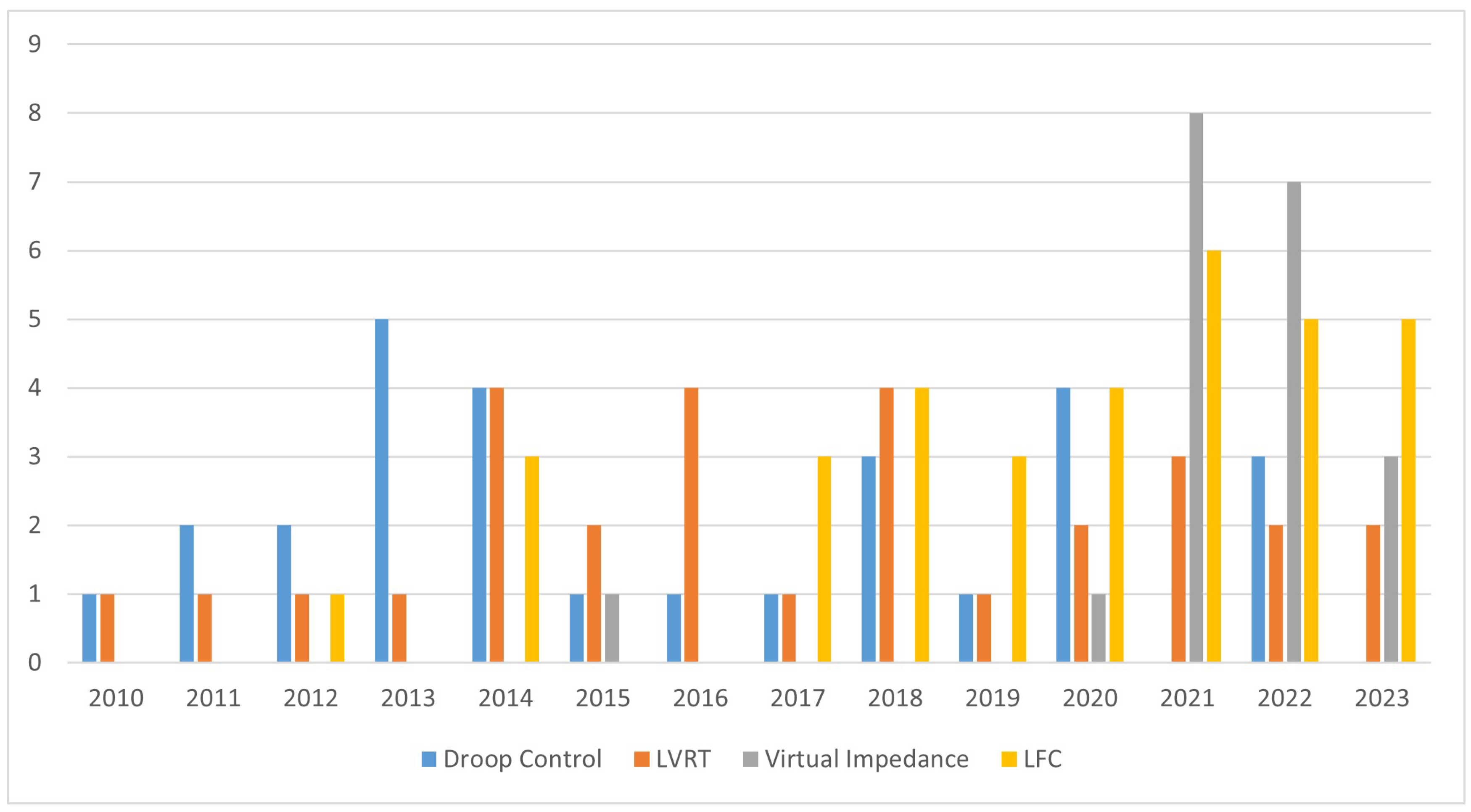
Appendix A
| Droop Control | LVRT | Virtual Impedance | Load Frequency Control | Year of Publication |
|---|---|---|---|---|
| [39] | [80,81] | - | - | 2016 |
| [38] | [64] | - | [117,118,144] | 2017 |
| [29] | [77,82] | - | [125,128,131,142,150] | 2018 |
| [33,53,57,58] | [67] | - | [116,129,143,148] | 2019 |
| [23,50,51,56] | [73,74] | [96] | [134,135,145,152] | 2020 |
| - | [65,66,75] | [91,94,97] | [119,132,136,137,138,139] | 2021 |
| [26,36,43] | [83] | [88,90,93,95] | [126,133,141,146,151] | 2022 |
| - | [84] | [92] | [110,121,140,149] | 2023 |
References
- Khaneghah, M.Z.; Abrishamifar, A. A Five-Switch Active NPC with Low Output Voltage THD for Photovoltaic Applications. In Proceedings of the 2019 10th International Power Electronics, Drive Systems and Technologies Conference (PEDSTC), Shiraz, Iran, 12–14 February 2019; pp. 752–757. [Google Scholar] [CrossRef]
- Alzayed, M.; Chaoui, H.; Farajpour, Y. Maximum Power Tracking for a Wind Energy Conversion System Using Cascade-Forward Neural Networks. IEEE Trans. Sustain. Energy 2021, 12, 2367–2377. [Google Scholar] [CrossRef]
- Akbari, A.; Poloei, F.; Bakhshai, A. A Brief Review on State-of-the-art Grid-connected Inverters for Photovoltaic Applications. In Proceedings of the 2019 IEEE 28th International Symposium on Industrial Electronics (ISIE), Vancouver, BC, Canada, 12–14 June 2019; pp. 1023–1028. [Google Scholar] [CrossRef]
- Alzayed, M.; Chaoui, H.; Elhaji, E.; Zhang, C. Universal Maximum Power Extraction Controller for Wind Energy Conversion Systems Using Deep Belief Neural Network. IEEE Trans. Sustain. Energy 2023, 14, 630–641. [Google Scholar] [CrossRef]
- Pinthurat, W.; Kongsuk, P.; Marungsri, B. Robust-Adaptive Controllers Designed for Grid-Forming Converters Ensuring Various Low-Inertia Microgrid Conditions. Smart Cities 2023, 6, 2944–2959. [Google Scholar] [CrossRef]
- Ardalan, P.; Rasekh, N.; Khaneghah, M.Z.; Abrishamifar, A.; Saeidi, M. A modified SOGI-FLL algorithm with DC-offset rejection improvement for single-phase inverter applications. Int. J. Dyn. Control 2022, 10, 2020–2033. [Google Scholar] [CrossRef]
- Zoka, Y.; Sasaki, H.; Yorino, N.; Kawahara, K.; Liu, C. An interaction problem of distributed generators installed in a MicroGrid. In Proceedings of the 2004 IEEE International Conference on Electric Utility Deregulation, Restructuring and Power Technologies. Proceedings, Hong Kong, China, 5–8 April 2004; Volume 2, pp. 795–799. [Google Scholar] [CrossRef]
- Ashabani, S.M.; Mohamed, Y.A.R.I. A Flexible Control Strategy for Grid-Connected and Islanded Microgrids with Enhanced Stability Using Nonlinear Microgrid Stabilizer. IEEE Trans. Smart Grid 2012, 3, 1291–1301. [Google Scholar] [CrossRef]
- Awad, B.; Wu, J.; Jenkins, N. Control of distributed generation. Elektrotech. Informationstech. 2008, 125, 409–414. [Google Scholar] [CrossRef]
- Mohamed, Y.A.R.I.; Radwan, A.A. Hierarchical Control System for Robust Microgrid Operation and Seamless Mode Transfer in Active Distribution Systems. IEEE Trans. Smart Grid 2011, 2, 352–362. [Google Scholar] [CrossRef]
- Batarseh, I.; Siri, K.; Lee, H. Investigation of the output droop characteristics of parallel-connnected DC-DC converters. In Proceedings of the 1994 Power Electronics Specialist Conference—PESC’94, Taipei, Taiwan, 20–25 June 1994; Volume 2, pp. 1342–1351. [Google Scholar] [CrossRef]
- Li, Y.W.; Kao, C.N. An Accurate Power Control Strategy for Power-Electronics-Interfaced Distributed Generation Units Operating in a Low-Voltage Multibus Microgrid. IEEE Trans. Power Electron. 2009, 24, 2977–2988. [Google Scholar] [CrossRef]
- Vandoorn, T.L.; Zwaenepoel, B.; De Kooning, J.D.M.; Meersman, B.; Vandevelde, L. Smart microgrids and virtual power plants in a hierarchical control structure. In Proceedings of the 2011 2nd IEEE PES International Conference and Exhibition on Innovative Smart Grid Technologies, Manchester, UK, 5–7 December 2011; pp. 1–7. [Google Scholar] [CrossRef]
- He, J.; Li, Y.W. Analysis, Design, and Implementation of Virtual Impedance for Power Electronics Interfaced Distributed Generation. IEEE Trans. Ind. Appl. 2011, 47, 2525–2538. [Google Scholar] [CrossRef]
- Wang, X.; Li, Y.W.; Blaabjerg, F.; Loh, P.C. Virtual-Impedance-Based Control for Voltage-Source and Current-Source Converters. IEEE Trans. Power Electron. 2015, 30, 7019–7037. [Google Scholar] [CrossRef]
- Doolla, S.; Bhatti, T. Load Frequency Control of an Isolated Small-Hydro Power Plant with Reduced Dump Load. IEEE Trans. Power Syst. 2006, 21, 1912–1919. [Google Scholar] [CrossRef]
- Rerkpreedapong, D.; Hasanovic, A.; Feliachi, A. Robust load frequency control using genetic algorithms and linear matrix inequalities. IEEE Trans. Power Syst. 2003, 18, 855–861. [Google Scholar] [CrossRef]
- Andishgar, M.H.; Gholipour, E.; allah Hooshmand, R. An overview of control approaches of inverter-based microgrids in islanding mode of operation. Renew. Sustain. Energy Rev. 2017, 80, 1043–1060. [Google Scholar] [CrossRef]
- Gonzales-Zurita, Ó.; Clairand, J.M.; Peñalvo-López, E.; Escrivá-Escrivá, G. Review on Multi-Objective Control Strategies for Distributed Generation on Inverter-Based Microgrids. Energies 2020, 13, 3483. [Google Scholar] [CrossRef]
- Muhtadi, A.; Pandit, D.; Nguyen, N.; Mitra, J. Distributed Energy Resources Based Microgrid: Review of Architecture, Control, and Reliability. IEEE Trans. Ind. Appl. 2021, 57, 2223–2235. [Google Scholar] [CrossRef]
- Asadi, Y.; Eskandari, M.; Mansouri, M.; Savkin, A.V.; Pathan, E. Frequency and Voltage Control Techniques through Inverter-Interfaced Distributed Energy Resources in Microgrids: A Review. Energies 2022, 15, 8580. [Google Scholar] [CrossRef]
- Hu, J.; Shan, Y.; Cheng, K.W.; Islam, S. Overview of Power Converter Control in Microgrids—Challenges, Advances, and Future Trends. IEEE Trans. Power Electron. 2022, 37, 9907–9922. [Google Scholar] [CrossRef]
- Ganjian-Aboukheili, M.; Shahabi, M.; Shafiee, Q.; Guerrero, J.M. Seamless Transition of Microgrids Operation From Grid-Connected to Islanded Mode. IEEE Trans. Smart Grid 2020, 11, 2106–2114. [Google Scholar] [CrossRef]
- Akbari, A.; Bakhshai, A. A Novel Multilevel Inverter Structure for Renewable Energy Applications. In Proceedings of the 2023 IEEE 14th International Conference on Power Electronics and Drive Systems (PEDS), Montreal, QC, Canada, 7–10 August 2023; pp. 1–6. [Google Scholar] [CrossRef]
- Alshareef, M.; Lin, Z.; Li, F.; Wang, F. A grid interface current control strategy for DC microgrids. CES Trans. Electr. Mach. Syst. 2021, 5, 249–256. [Google Scholar] [CrossRef]
- Alzayed, M.; Lemaire, M.; Zarrabian, S.; Chaoui, H.; Massicotte, D. Droop-Controlled Bidirectional Inverter-Based Microgrid Using Cascade-Forward Neural Networks. IEEE Open J. Circuits Syst. 2022, 3, 298–308. [Google Scholar] [CrossRef]
- Guerrero, J.M.; Vasquez, J.C.; Matas, J.; de Vicuna, L.G.; Castilla, M. Hierarchical Control of Droop-Controlled AC and DC Microgrids—A General Approach Toward Standardization. IEEE Trans. Ind. Electron. 2011, 58, 158–172. [Google Scholar] [CrossRef]
- Rocabert, J.; Luna, A.; Blaabjerg, F.; Rodríguez, P. Control of Power Converters in AC Microgrids. IEEE Trans. Power Electron. 2012, 27, 4734–4749. [Google Scholar] [CrossRef]
- Gupta, A.; Doolla, S.; Chatterjee, K. Hybrid AC–DC Microgrid: Systematic Evaluation of Control Strategies. IEEE Trans. Smart Grid 2018, 9, 3830–3843. [Google Scholar] [CrossRef]
- Kundur, P. Power System Stability and Control, 1st ed.; McGraw-Hill: New York, NY, USA, 1994. [Google Scholar]
- Barsali, S.; Ceraolo, M.; Pelacchi, P.; Poli, D. Control techniques of Dispersed Generators to improve the continuity of electricity supply. In Proceedings of the 2002 IEEE Power Engineering Society Winter Meeting. Conference Proceedings (Cat. No.02CH37309), New York, NY, USA, 27–31 January 2002; Volume 2, pp. 789–794. [Google Scholar] [CrossRef]
- Vandoorn, T.L.; De Kooning, J.D.M.; Meersman, B.; Guerrero, J.M.; Vandevelde, L. Automatic Power-Sharing Modification of P/V Droop Controllers in Low-Voltage Resistive Microgrids. IEEE Trans. Power Deliv. 2012, 27, 2318–2325. [Google Scholar] [CrossRef]
- Peyghami, S.; Davari, P.; Mokhtari, H.; Blaabjerg, F. Decentralized Droop Control in DC Microgrids Based on a Frequency Injection Approach. IEEE Trans. Smart Grid 2019, 10, 6782–6791. [Google Scholar] [CrossRef]
- Vandoorn, T.L.; Meersman, B.; De Kooning, J.D.M.; Vandevelde, L. Transition From Islanded to Grid-Connected Mode of Microgrids with Voltage-Based Droop Control. IEEE Trans. Power Syst. 2013, 28, 2545–2553. [Google Scholar] [CrossRef]
- Hu, J.; Zhu, J.; Dorrell, D.G.; Guerrero, J.M. Virtual Flux Droop Method—A New Control Strategy of Inverters in Microgrids. IEEE Trans. Power Electron. 2014, 29, 4704–4711. [Google Scholar] [CrossRef]
- Cao, W.; Han, M.; Zhang, X.; Guan, Y.; Guerrero, J.M.; Vasquez, J.C. An Integrated Synchronization and Control Strategy for Parallel-Operated Inverters Based on V–I Droop Characteristics. IEEE Trans. Power Electron. 2022, 37, 5373–5384. [Google Scholar] [CrossRef]
- Golsorkhi, M.S.; Lu, D.D.C. A Control Method for Inverter-Based Islanded Microgrids Based on V-I Droop Characteristics. IEEE Trans. Power Deliv. 2015, 30, 1196–1204. [Google Scholar] [CrossRef]
- Pasha, A.M.; Zeineldin, H.H.; Al-Sumaiti, A.S.; Moursi, M.S.E.; Sadaany, E.F.E. Conservation Voltage Reduction for Autonomous Microgrids Based on V–I Droop Characteristics. IEEE Trans. Sustain. Energy 2017, 8, 1076–1085. [Google Scholar] [CrossRef]
- Raj, D.C.; Gaonkar, D.N. Frequency and voltage droop control of parallel inverters in microgrid. In Proceedings of the 2016 2nd International Conference on Control, Instrumentation, Energy & Communication (CIEC), Kolkata, India, 28–30 January 2016; pp. 407–411. [Google Scholar] [CrossRef]
- Marwali, M.; Jung, J.W.; Keyhani, A. Control of distributed generation systems—Part II: Load sharing control. IEEE Trans. Power Electron. 2004, 19, 1551–1561. [Google Scholar] [CrossRef]
- Tuladhar, A.; Jin, H.; Unger, T.; Mauch, K. Parallel operation of single phase inverter modules with no control interconnections. In Proceedings of the APEC 97—Applied Power Electronics Conference, Atlanta, GA, USA, 27 February 1997; Volume 1, pp. 94–100. [Google Scholar] [CrossRef]
- De Brabandere, K.; Bolsens, B.; Van den Keybus, J.; Woyte, A.; Driesen, J.; Belmans, R. A Voltage and Frequency Droop Control Method for Parallel Inverters. IEEE Trans. Power Electron. 2007, 22, 1107–1115. [Google Scholar] [CrossRef]
- Minetti, M.; Rosini, A.; Denegri, G.B.; Bonfiglio, A.; Procopio, R. An Advanced Droop Control Strategy for Reactive Power Assessment in Islanded Microgrids. IEEE Trans. Power Syst. 2022, 37, 3014–3025. [Google Scholar] [CrossRef]
- Oudalov, A.; Chartouni, D.; Ohler, C. Optimizing a Battery Energy Storage System for Primary Frequency Control. IEEE Trans. Power Syst. 2007, 22, 1259–1266. [Google Scholar] [CrossRef]
- Velasco de la Fuente, D.; Trujillo Rodríguez, C.L.; Garcerá, G.; Figueres, E.; Ortega Gonzalez, R. Photovoltaic Power System with Battery Backup with Grid-Connection and Islanded Operation Capabilities. IEEE Trans. Ind. Electron. 2013, 60, 1571–1581. [Google Scholar] [CrossRef]
- Lawder, M.T.; Suthar, B.; Northrop, P.W.C.; De, S.; Hoff, C.M.; Leitermann, O.; Crow, M.L.; Santhanagopalan, S.; Subramanian, V.R. Battery Energy Storage System (BESS) and Battery Management System (BMS) for Grid-Scale Applications. Proc. IEEE 2014, 102, 1014–1030. [Google Scholar] [CrossRef]
- Kim, J.Y.; Jeon, J.H.; Kim, S.K.; Cho, C.; Park, J.H.; Kim, H.M.; Nam, K.Y. Cooperative Control Strategy of Energy Storage System and Microsources for Stabilizing the Microgrid during Islanded Operation. IEEE Trans. Power Electron. 2010, 25, 3037–3048. [Google Scholar] [CrossRef]
- Serban, I.; Teodorescu, R.; Marinescu, C. Energy storage systems impact on the short-term frequency stability of distributed autonomous microgrids, an analysis using aggregate models. IET Renew. Power Gen. 2013, 7, 531–539. [Google Scholar] [CrossRef]
- Serban, I.; Marinescu, C. Control Strategy of Three-Phase Battery Energy Storage Systems for Frequency Support in Microgrids and with Uninterrupted Supply of Local Loads. IEEE Trans. Power Electron. 2014, 29, 5010–5020. [Google Scholar] [CrossRef]
- Zhu, D.; Zhang, Y.J.A. Optimal Coordinated Control of Multiple Battery Energy Storage Systems for Primary Frequency Regulation. IEEE Trans. Power Syst. 2019, 34, 555–565. [Google Scholar] [CrossRef]
- Datta, U.; Kalam, A.; Shi, J. Battery Energy Storage System Control for Mitigating PV Penetration Impact on Primary Frequency Control and State-of-Charge Recovery. IEEE Trans. Sustain. Energy 2020, 11, 746–757. [Google Scholar] [CrossRef]
- Wu, D.; Tang, F.; Dragicevic, T.; Vasquez, J.C.; Guerrero, J.M. Autonomous Active Power Control for Islanded AC Microgrids with Photovoltaic Generation and Energy Storage System. IEEE Trans. Energy Convers. 2014, 29, 882–892. [Google Scholar] [CrossRef]
- Zhao, H.; Hong, M.; Lin, W.; Loparo, K.A. Voltage and Frequency Regulation of Microgrid with Battery Energy Storage Systems. IEEE Trans. Smart Grid 2019, 10, 414–424. [Google Scholar] [CrossRef]
- Nguyen, D.H.; Khazaei, J. Unified Distributed Control of Battery Storage with Various Primary Control in Power Systems. IEEE Trans. Sustain. Energy 2021, 12, 2332–2341. [Google Scholar] [CrossRef]
- Han, J.; Solanki, S.K.; Solanki, J. Coordinated Predictive Control of a Wind/Battery Microgrid System. IEEE J. Emerg. Sel. Top. Power Electron. 2013, 1, 296–305. [Google Scholar] [CrossRef]
- Gomez, L.A.G.; Lourenço, L.F.N.; Grilo, A.P.; Salles, M.B.C.; Meegahapola, L.; Filho, A.J.S. Primary Frequency Response of Microgrid Using Doubly Fed Induction Generator with Finite Control Set Model Predictive Control Plus Droop Control and Storage System. IEEE Access 2020, 8, 189298–189312. [Google Scholar] [CrossRef]
- Zhang, Y.J.A.; Zhao, C.; Tang, W.; Low, S.H. Profit-Maximizing Planning and Control of Battery Energy Storage Systems for Primary Frequency Control. IEEE Trans. Smart Grid 2018, 9, 712–723. [Google Scholar] [CrossRef]
- Jia, J.; Yang, G.; Nielsen, A.H. A Review on Grid-Connected Converter Control for Short-Circuit Power Provision Under Grid Unbalanced Faults. IEEE Trans. Power Deliv. 2018, 33, 649–661. [Google Scholar] [CrossRef]
- Garnica López, M.A.; García de Vicuña, J.L.; Miret, J.; Castilla, M.; Guzmán, R. Control Strategy for Grid-Connected Three-Phase Inverters during Voltage Sags to Meet Grid Codes and to Maximize Power Delivery Capability. IEEE Trans. Power Electron. 2018, 33, 9360–9374. [Google Scholar] [CrossRef]
- Graungaard Taul, M.; Wang, X.; Davari, P.; Blaabjerg, F. Current Reference Generation Based on Next-Generation Grid Code Requirements of Grid-Tied Converters during Asymmetrical Faults. IEEE J. Emerg. Sel. Top. Power Electron. 2020, 8, 3784–3797. [Google Scholar] [CrossRef]
- Azizi, A.; Banaiemoqadam, A.; Hooshyar, A.; Patel, M. A Blind Spot in the LVRT Current Requirements of Modern Grid Codes for Inverter-Based Resources. IEEE Trans. Power Deliv. 2023, 38, 319–334. [Google Scholar] [CrossRef]
- Teodorescu, R.; Liserre, M.; Rodríguez, P. Grid Converters for Photovoltaic and Wind Power Systems; Wiley: Chichester, UK, 2010. [Google Scholar]
- Hu, Y.L.; Wu, Y.K.; Chen, C.K.; Wang, C.H.; Chen, W.T.; Cho, L.I. A Review of the Low-Voltage Ride-Through Capability of Wind Power Generators. Energy Procedia 2017, 141, 378–382. [Google Scholar] [CrossRef]
- Haidar, A.M.A.; Muttaqi, K.M.; Hagh, M.T. A Coordinated Control Approach for DC link and Rotor Crowbars to Improve Fault Ride-Through of DFIG-Based Wind Turbine. IEEE Trans. Ind. Appl. 2017, 53, 4073–4086. [Google Scholar] [CrossRef]
- Zhou, L.; Swain, A.; Ukil, A. Reinforcement Learning Controllers for Enhancement of Low Voltage Ride Through Capability in Hybrid Power Systems. IEEE Trans. Ind. Inform. 2020, 16, 5023–5031. [Google Scholar] [CrossRef]
- Liu, M.; Pan, W.; Rao, Y.; Li, C.; Liu, T.; Zhu, Z.; Zhang, Y. An Electromagnetic Transient Analysis Model for DFIG Considering LVRT Hardware Protection. IEEE Access 2021, 9, 32591–32598. [Google Scholar] [CrossRef]
- Jiang, H.; Zhang, C. A Method of Boosting Transient Stability of Wind Farm Connected Power System Using S Magnetic Energy Storage Unit. IEEE Trans. Appl. Supercond. 2019, 29, 5700605. [Google Scholar] [CrossRef]
- Yang, J.; Fletcher, J.E.; O’Reilly, J. A Series-Dynamic-Resistor-Based Converter Protection Scheme for Doubly-Fed Induction Generator during Various Fault Conditions. IEEE Trans. Energy Convers. 2010, 25, 422–432. [Google Scholar] [CrossRef]
- Okedu, K.E.; Muyeen, S.M.; Takahashi, R.; Tamura, J. Wind Farms Fault Ride through Using DFIG with New Protection Scheme. IEEE Trans. Sustain. Energy 2012, 3, 242–254. [Google Scholar] [CrossRef]
- Elshiekh, M.E.; Mansour, D.E.A.; Azmy, A.M. Improving Fault Ride-Through Capability of DFIG-Based Wind Turbine Using Superconducting Fault Current Limiter. IEEE Trans. Appl. Supercond. 2013, 23, 5601204. [Google Scholar] [CrossRef]
- Molinas, M.; Suul, J.A.; Undeland, T. A simple method for analytical evaluation of LVRT in wind energy for induction generators with STATCOM or SVC. In Proceedings of the 2007 European Conference on Power Electronics and Applications, Aalborg, Denmark, 2–5 September 2007; pp. 1–10. [Google Scholar] [CrossRef]
- Pereira, M.; Retzmann, D.; Lottes, J.; Wiesinger, M.; Wong, G. SVC PLUS: An MMC STATCOM for network and grid access applications. In Proceedings of the 2011 IEEE Trondheim PowerTech, Trondheim, Norway, 19–23 June 2011; pp. 1–5. [Google Scholar] [CrossRef]
- Kim, C.; Kim, W. Enhanced Low-Voltage Ride-Through Coordinated Control for PMSG Wind Turbines and Energy Storage Systems Considering Pitch and Inertia Response. IEEE Access 2020, 8, 212557–212567. [Google Scholar] [CrossRef]
- Zhou, A.; Li, Y.W.; Mohamed, Y. Mechanical Stress Comparison of PMSG Wind Turbine LVRT Methods. IEEE Trans. Energy Convers. 2021, 36, 682–692. [Google Scholar] [CrossRef]
- Kabsha, M.M.; Rather, Z.H. Advanced LVRT Control Scheme for Offshore Wind Power Plant. IEEE Trans. Power Deliv. 2021, 36, 3893–3902. [Google Scholar] [CrossRef]
- Yang, Y.; Wang, H.; Blaabjerg, F. Reactive Power Injection Strategies for Single-Phase Photovoltaic Systems Considering Grid Requirements. IEEE Trans. Ind. Appl. 2014, 50, 4065–4076. [Google Scholar] [CrossRef]
- Mohammadi, P.; Eskandari, A.; Milimonfared, J.; Moghani, J.S. LVRT capability enhancement of single-phase grid connected PV array with coupled supercapacitor. In Proceedings of the 2018 9th Annual Power Electronics, Drives Systems and Technologies Conference (PEDSTC), Tehran, Iran, 13–15 February 2018; pp. 193–198. [Google Scholar] [CrossRef]
- Varma, R.K.; Siavashi, E.M. PV-STATCOM: A New Smart Inverter for Voltage Control in Distribution Systems. IEEE Trans. Sustain. Energy 2018, 9, 1681–1691. [Google Scholar] [CrossRef]
- Tang, C.Y.; Chen, Y.T.; Chen, Y.M. PV Power System with Multi-Mode Operation and Low-Voltage Ride-Through Capability. IEEE Trans. Ind. Electron. 2015, 62, 7524–7533. [Google Scholar] [CrossRef]
- Hasanien, H.M. An Adaptive Control Strategy for Low Voltage Ride Through Capability Enhancement of Grid-Connected Photovoltaic Power Plants. IEEE Trans. Power Syst. 2016, 31, 3230–3237. [Google Scholar] [CrossRef]
- Moghadasi, A.; Sargolzaei, A.; Khalilnejad, A.; Moghaddami, M.; Sarwat, A. Model predictive power control approach for three-phase single-stage grid-tied PV module-integrated converter. In Proceedings of the 2016 IEEE Industry Applications Society Annual Meeting, Portland, OR, USA, 2–6 October 2016; pp. 1–6. [Google Scholar] [CrossRef]
- Das, P.P.; Chattopadhyay, S. A Voltage-Independent Islanding Detection Method and Low-Voltage Ride Through of a Two-Stage PV Inverter. IEEE Trans. Ind. Appl. 2018, 54, 2773–2783. [Google Scholar] [CrossRef]
- Zhao, T.; Feng, Z.; Wang, M.; Wu, M.; Chen, D. An Optimized LVRT Control Strategy of Cascaded Modular Medium-Voltage Inverter for Large-Scale PV Power Plant. IEEE J. Emerg. Sel. Top. Power Electron. 2022, 10, 7744–7759. [Google Scholar] [CrossRef]
- Alrumayh, O.; Sayed, K.; Almutairi, A. LVRT and Reactive Power/Voltage Support of Utility-Scale PV Power Plants during Disturbance Conditions. Energies 2023, 16, 3245. [Google Scholar] [CrossRef]
- Yang, F.; Yang, L.; Ma, X. An Advanced Control Strategy of PV System for Low-Voltage Ride-through Capability Enhancement. Sol. Energy 2014, 109, 24–35. [Google Scholar] [CrossRef]
- Velasco, M.; Alfaro, C.; Camacho, A.; Borrell, A.; Martí, P. Complex Power Sharing Is Not Complex. IEEE Trans. Smart Grid 2022, 13, 1762–1773. [Google Scholar] [CrossRef]
- Sabzevari, K.; Karimi, S.; Khosravi, F.; Abdi, H. Modified Droop Control for Improving Adaptive Virtual Impedance Strategy for Parallel Distributed Generation Units in Islanded Microgrids. Int. Trans. Electr. Energy Syst. 2019, 29, e2689. [Google Scholar] [CrossRef]
- Ahmed, M.; Meegahapola, L.; Vahidnia, A.; Datta, M. Adaptive Virtual Impedance Controller for Parallel and Radial Microgrids with Varying X/R Ratios. IEEE Trans. Sustain. Energy 2022, 13, 830–843. [Google Scholar] [CrossRef]
- Mahmood, H.; Michaelson, D.; Jiang, J. Accurate Reactive Power Sharing in an Islanded Microgrid Using Adaptive Virtual Impedances. IEEE Trans. Power Electron. 2015, 30, 1605–1617. [Google Scholar] [CrossRef]
- Fan, B.; Li, Q.; Wang, W.; Yao, G.; Ma, H.; Zeng, X.; Guerrero, J.M. A Novel Droop Control Strategy of Reactive Power Sharing Based on Adaptive Virtual Impedance in Microgrids. IEEE Trans. Ind. Electron. 2022, 69, 11335–11347. [Google Scholar] [CrossRef]
- Pham, M.D.; Lee, H.H. Effective Coordinated Virtual Impedance Control for Accurate Power Sharing in Islanded Microgrid. IEEE Trans. Ind. Electron. 2021, 68, 2279–2288. [Google Scholar] [CrossRef]
- Chen, W.; Zhang, Y.; Tu, Y.; Guan, Y.; Shen, K.; Liu, J. Unified Active Damping Strategy Based on Generalized Virtual Impedance in LCL-Type Grid-Connected Inverter. IEEE Trans. Ind. Electron. 2023, 70, 8129–8139. [Google Scholar] [CrossRef]
- Das, H.S.; Li, S.; Lu, B.; Wang, J. Virtual Dynamic Grid Impedance and Its Impacts on Harmonics and Stability of Inverter Based Resources Plant. IEEE Trans. Power Electron. 2022, 37, 15469–15481. [Google Scholar] [CrossRef]
- Vijay, A.S.; Parth, N.; Doolla, S.; Chandorkar, M.C. An Adaptive Virtual Impedance Control for Improving Power Sharing Among Inverters in Islanded AC Microgrids. IEEE Trans. Smart Grid 2021, 12, 2991–3003. [Google Scholar] [CrossRef]
- Khanabdal, S.; Banejad, M.; Blaabjerg, F.; Hosseinzadeh, N. Adaptive Virtual Flux Droop Control Based on Virtual Impedance in Islanded AC Microgrids. IEEE J. Emerg. Sel. Top. Power Electron. 2022, 10, 1095–1107. [Google Scholar] [CrossRef]
- Wong, Y.C.C.; Lim, C.S.; Rotaru, M.D.; Cruden, A.; Kong, X. Consensus Virtual Output Impedance Control Based on the Novel Droop Equivalent Impedance Concept for a Multi-Bus Radial Microgrid. IEEE Trans. Energy Convers. 2020, 35, 1078–1087. [Google Scholar] [CrossRef]
- Wong, Y.C.C.; Lim, C.S.; Cruden, A.; Rotaru, M.D.; Ray, P.K. A Consensus-Based Adaptive Virtual Output Impedance Control Scheme for Reactive Power Sharing in Radial Microgrids. IEEE Trans. Ind. Appl. 2021, 57, 784–794. [Google Scholar] [CrossRef]
- Keyvani-Boroujeni, B.; Fani, B.; Shahgholian, G.; Alhelou, H.H. Virtual Impedance-Based Droop Control Scheme to Avoid Power Quality and Stability Problems in VSI-Dominated Microgrids. IEEE Access 2021, 9, 144999–145011. [Google Scholar] [CrossRef]
- Vijay, A.S.; Doolla, S.; Chandorkar, M.C. Varying Negative Sequence Virtual Impedance Adaptively for Enhanced Unbalanced Power Sharing Among DGs in Islanded AC Microgrids. IEEE Trans. Energy Convers. 2021, 36, 3271–3281. [Google Scholar] [CrossRef]
- Budiwicaksana, L.A.; Ardriani, T.; Furqani, J.; Rizqiawan, A.; Dahono, P.A. Improving Inverter Output Current Controller Under Unbalanced Conditions by Using Virtual Impedance. IEEE Access 2021, 9, 162359–162369. [Google Scholar] [CrossRef]
- Li, Z.; Chan, K.W.; Hu, J.; Guerrero, J.M. Adaptive Droop Control Using Adaptive Virtual Impedance for Microgrids with Variable PV Outputs and Load Demands. IEEE Trans. Ind. Electron. 2021, 68, 9630–9640. [Google Scholar] [CrossRef]
- Liang, X.; Andalib-Bin-Karim, C.; Li, W.; Mitolo, M.; Shabbir, M.N.S.K. Adaptive Virtual Impedance-Based Reactive Power Sharing in Virtual Synchronous Generator Controlled Microgrids. IEEE Trans. Ind. Appl. 2021, 57, 46–60. [Google Scholar] [CrossRef]
- Perez, F.; Damm, G.; Verrelli, C.M.; Ribeiro, P.F. Adaptive Virtual Inertia Control for Stable Microgrid Operation Including Ancillary Services Support. IEEE Trans. Control Syst. Technol. 2023, 31, 1552–1564. [Google Scholar] [CrossRef]
- Pournazarian, B.; Sangrody, R.; Lehtonen, M.; Gharehpetian, G.B.; Pouresmaeil, E. Simultaneous Optimization of Virtual Synchronous Generators Parameters and Virtual Impedances in Islanded Microgrids. IEEE Trans. Smart Grid 2022, 13, 4202–4217. [Google Scholar] [CrossRef]
- Wu, H.; Wang, X. Small-Signal Modeling and Controller Parameters Tuning of Grid-Forming VSCs with Adaptive Virtual Impedance-Based Current Limitation. IEEE Trans. Power Electron. 2022, 37, 7185–7199. [Google Scholar] [CrossRef]
- Sati, T.; Azzouz, M. An adaptive virtual impedance fault current limiter for optimal protection coordination of islanded microgrids. IET Renew. Power Gener. 2022, 16, 1719–1732. [Google Scholar] [CrossRef]
- Sati, T.E.; Azzouz, M.A.; Shaaban, M. Optimal Protection Coordination of Islanded Microgrids Utilizing an Adaptive Virtual Impedance Fault Current Limiter. IEEE Trans. Ind. Appl. 2023, 59, 2866–2876. [Google Scholar] [CrossRef]
- Ali, W.; Ulasyar, A.; Mehmood, M.U.; Khattak, A.; Imran, K.; Zad, H.S.; Nisar, S. Hierarchical Control of Microgrid Using IoT and Machine Learning Based Islanding Detection. IEEE Access 2021, 9, 103019–103031. [Google Scholar] [CrossRef]
- Chen, J.; Yue, D.; Dou, C.; Chen, L.; Weng, S.; Li, Y. A Virtual Complex Impedance Based Droop Method for Parallel-Connected Inverters in Low-Voltage AC Microgrids. IEEE Trans. Ind. Inform. 2021, 17, 1763–1773. [Google Scholar] [CrossRef]
- Egbomwan, O.E.; Liu, S.; Chaoui, H. Twin Delayed Deep Deterministic Policy Gradient (TD3) Based Virtual Inertia Control for Inverter-Interfacing DGs in Microgrids. IEEE Syst. J. 2023, 17, 2122–2132. [Google Scholar] [CrossRef]
- Bevrani, H. Robust Power System Frequency Control; Springer: Cham, Switzerland, 2014. [Google Scholar] [CrossRef]
- Gross, G.; Lee, J.W. Analysis of load frequency control performance assessment criteria. IEEE Trans. Power Syst. 2001, 16, 520–525. [Google Scholar] [CrossRef]
- Kundur, P.; Paserba, J.; Ajjarapu, V.; Andersson, G.; Bose, A.; Canizares, C.; Hatziargyriou, N.; Hill, D.; Stankovic, A.; Taylor, C.; et al. Definition and classification of power system stability IEEE/CIGRE joint task force on stability terms and definitions. IEEE Trans. Power Syst. 2004, 19, 1387–1401. [Google Scholar] [CrossRef]
- Ellithy, K.; El-Metwally, K. Design of Decentralized Fuzzy Logic Load Frequency Controller. Int. J. Intell. Syst. Appl. 2012, 4, 66–75. [Google Scholar] [CrossRef]
- Richalet, J.; Rault, A.; Testud, J.; Papon, J. Model predictive heuristic control: Applications to industrial processes. Automatica 1978, 14, 413–428. [Google Scholar] [CrossRef]
- Liu, J.; Yao, Q.; Hu, Y. Model predictive control for load frequency of hybrid power system with wind power and thermal power. Energy 2019, 172, 555–565. [Google Scholar] [CrossRef]
- Mir, A.S.; Senroy, N. Adaptive Model Predictive Control Scheme for Application of SMES for Load Frequency Control. IEEE Trans. Power Syst. 2017, 1. [Google Scholar] [CrossRef]
- Su, X.; Liu, X.; Song, Y.D. Event-Triggered Sliding-Mode Control for Multi-Area Power Systems. IEEE Trans. Ind. Electron. 2017, 64, 6732–6741. [Google Scholar] [CrossRef]
- Wang, Z.; Liu, Y. Adaptive Terminal Sliding Mode Based Load Frequency Control for Multi-Area Interconnected Power Systems with PV and Energy Storage. IEEE Access 2021, 9, 120185–120192. [Google Scholar] [CrossRef]
- Chaoui, H.; Gueaieb, W. Type-2 Fuzzy Logic Control of a Flexible-Joint Manipulator. J. Intell. Robot. Syst. 2008, 51, 159–186. [Google Scholar] [CrossRef]
- Elhaj, A.; Alzayed, M.; Chaoui, H. Multiparameter Estimation-Based Sensorless Adaptive Direct Voltage MTPA Control for IPMSM Using Fuzzy Logic MRAS. Machines 2023, 11, 861. [Google Scholar] [CrossRef]
- El-Sherbiny, M.; El-Saady, G.; Yousef, A. Efficient fuzzy logic load–frequency controller. Energy Convers. Manag. 2002, 43, 1853–1863. [Google Scholar] [CrossRef]
- Wang, H.; Li, Z.S. Multi-Area Load Frequency Control in Power System Integrated with Wind Farms Using Fuzzy Generalized Predictive Control Method. IEEE Trans. Reliab. 2023, 72, 737–747. [Google Scholar] [CrossRef]
- Kang, J.; Meng, W.; Abraham, A.; Liu, H. An adaptive PID neural network for complex nonlinear system control. Neurocomputing 2014, 135, 79–85. [Google Scholar] [CrossRef]
- Xu, D.; Liu, J.; Yan, X.G.; Yan, W. A Novel Adaptive Neural Network Constrained Control for a Multi-Area Interconnected Power System with Hybrid Energy Storage. IEEE Trans. Ind. Electron. 2018, 65, 6625–6634. [Google Scholar] [CrossRef]
- Al-Majidi, S.D.; Kh. AL-Nussairi, M.; Mohammed, A.J.; Dakhil, A.M.; Abbod, M.F.; Al-Raweshidy, H.S. Design of a Load Frequency Controller Based on an Optimal Neural Network. Energies 2022, 15, 6223. [Google Scholar] [CrossRef]
- Storn, R.; Price, K. Differential Evolution—A Simple and Efficient Heuristic for global Optimization over Continuous Spaces. J. Glob. Optim. 1997, 11, 341–359. [Google Scholar] [CrossRef]
- Li, H.; Wang, X.; Xiao, J. Differential Evolution-Based Load Frequency Robust Control for Micro-Grids with Energy Storage Systems. Energies 2018, 11, 1686. [Google Scholar] [CrossRef]
- Cao, W.; Liu, K.; Wu, M.; Xu, S.; Zhao, J. An Improved Current Control Strategy Based on Particle Swarm Optimization and Steady-State Error Correction for SAPF. IEEE Trans. Ind. Appl. 2019, 55, 4268–4274. [Google Scholar] [CrossRef]
- Yang, X.S. Cuckoo Search and Firefly Algorithm: Theory and Applications; Springer International Publishing: Cham, Switzerland, 2014. [Google Scholar]
- Abd-Elazim, S.; Ali, E. Firefly algorithm-based load frequency controller design of a two area system composing of PV grid and thermal generator. Electr. Eng. 2018, 100, 1253–1262. [Google Scholar] [CrossRef]
- Shangguan, X.C.; Zhang, C.K.; He, Y.; Jin, L.; Jiang, L.; Spencer, J.W.; Wu, M. Robust Load Frequency Control for Power System Considering Transmission Delay and Sampling Period. IEEE Trans. Ind. Inform. 2021, 17, 5292–5303. [Google Scholar] [CrossRef]
- Luo, H.; Hu, Z. Stability Analysis of Sampled-Data Load Frequency Control Systems with Multiple Delays. IEEE Trans. Control Syst. Technol. 2022, 30, 434–442. [Google Scholar] [CrossRef]
- Nguyen, T.T.; Nguyen, N.D.; Nahavandi, S. Deep Reinforcement Learning for Multiagent Systems: A Review of Challenges, Solutions, and Applications. IEEE Trans. Cybern. 2020, 50, 3826–3839. [Google Scholar] [CrossRef] [PubMed]
- Yan, Z.; Xu, Y. A Multi-Agent Deep Reinforcement Learning Method for Cooperative Load Frequency Control of a Multi-Area Power System. IEEE Trans. Power Syst. 2020, 35, 4599–4608. [Google Scholar] [CrossRef]
- Liu, H.; Xu, F.; Fan, P.; Liu, L.; Wen, H.; Qiu, Y.; Ke, S.; Li, Y.; Yang, J. Load Frequency Control Strategy of Island Microgrid with Flexible Resources Based on DQN. In Proceedings of the 2021 IEEE Sustainable Power and Energy Conference (iSPEC), Nanjing, China, 23–25 December 2021; pp. 632–637. [Google Scholar] [CrossRef]
- Zheng, Y.; Sun, Q.; Chen, Z.; Sun, M.; Tao, J.; Sun, H. Deep Q-Network based real-time active disturbance rejection controller parameter tuning for multi-area interconnected power systems. Neurocomputing 2021, 460, 360–373. [Google Scholar] [CrossRef]
- Oshnoei, A.; Kheradmandi, M.; Khezri, R.; Mahmoudi, A. Robust Model Predictive Control of Gate-Controlled Series Capacitor for LFC of Power Systems. IEEE Trans. Ind. Inform. 2021, 17, 4766–4776. [Google Scholar] [CrossRef]
- Gbadega, P.A.; Saha, A.K. Load Frequency Control of a Two-Area Power System with a Stand-Alone Microgrid Based on Adaptive Model Predictive Control. IEEE J. Emerg. Sel. Top. Power Electron. 2021, 9, 7253–7263. [Google Scholar] [CrossRef]
- Tang, X.; Li, Y.; Yang, M.; Wu, Y.; Wen, Y. Adaptive Event-Triggered Model Predictive Load Frequency Control for Power Systems. IEEE Trans. Power Syst. 2023, 38, 4003–4014. [Google Scholar] [CrossRef]
- Deng, Z.; Xu, C.; Huo, Z.; Han, X.; Xue, F. Sliding Mode Based Load Frequency Control and Power Smoothing of Power Systems with Wind and BESS Penetration. Machines 2022, 10, 1225. [Google Scholar] [CrossRef]
- Liao, K.; Xu, Y. A Robust Load Frequency Control Scheme for Power Systems Based on Second-Order Sliding Mode and Extended Disturbance Observer. IEEE Trans. Ind. Inform. 2018, 14, 3076–3086. [Google Scholar] [CrossRef]
- Li, H.; Wang, X.; Xiao, J. Adaptive Event-Triggered Load Frequency Control for Interconnected Microgrids by Observer-Based Sliding Mode Control. IEEE Access 2019, 7, 68271–68280. [Google Scholar] [CrossRef]
- Mu, C.; Tang, Y.; He, H. Improved Sliding Mode Design for Load Frequency Control of Power System Integrated an Adaptive Learning Strategy. IEEE Trans. Ind. Electron. 2017, 64, 6742–6751. [Google Scholar] [CrossRef]
- Lv, X.; Sun, Y.; Wang, Y.; Dinavahi, V. Adaptive Event-Triggered Load Frequency Control of Multi-Area Power Systems Under Networked Environment via Sliding Mode Control. IEEE Access 2020, 8, 86585–86594. [Google Scholar] [CrossRef]
- Shafei, M.A.R.; Ibrahim, D.K.; Bahaa, M. Application of PSO tuned fuzzy logic controller for LFC of two-area power system with redox flow battery and PV solar park. Ain Shams Eng. J. 2022, 13, 101710. [Google Scholar] [CrossRef]
- Talaq, J.; Al-Basri, F. Adaptive fuzzy gain scheduling for load frequency control. IEEE Trans. Power Syst. 1999, 14, 145–150. [Google Scholar] [CrossRef]
- Aziz, S.; Wang, H.; Liu, Y.; Peng, J.; Jiang, H. Variable Universe Fuzzy Logic-Based Hybrid LFC Control with Real-Time Implementation. IEEE Access 2019, 7, 25535–25546. [Google Scholar] [CrossRef]
- Mi, Y.; Ma, Y.; He, X.; Yang, X.; Gong, J.; Zhao, Y.; Liu, R.; Wei, W. Robust Load Frequency Control for Isolated Microgrids Based on Double-loop Compensation. CSEE J. Power Energy Syst. 2023, 9, 1359–1369. [Google Scholar] [CrossRef]
- Xu, Y.; Li, C.; Wang, Z.; Zhang, N.; Peng, B. Load Frequency Control of a Novel Renewable Energy Integrated Micro-Grid Containing Pumped Hydropower Energy Storage. IEEE Access 2018, 6, 29067–29077. [Google Scholar] [CrossRef]
- Zheng, Y.; Huang, Z.; Tao, J.; Sun, H.; Sun, Q.; Sun, M.; Dehmer, M.; Chen, Z. A Novel Chaotic Fractional-Order Beetle Swarm Optimization Algorithm and Its Application for Load-Frequency Active Disturbance Rejection Control. IEEE Trans. Circuits Syst. II Express Briefs 2022, 69, 1267–1271. [Google Scholar] [CrossRef]
- Mohamed, E.A.; Ahmed, E.M.; Elmelegi, A.; Aly, M.; Elbaksawi, O.; Mohamed, A.A.A. An Optimized Hybrid Fractional Order Controller for Frequency Regulation in Multi-Area Power Systems. IEEE Access 2020, 8, 213899–213915. [Google Scholar] [CrossRef]


| Methods | Feature | Configuration (Islanded/Grid-Connected) | Ref. |
|---|---|---|---|
| Power–frequency (P/f) droop | Regulate the real power flow by adjusting the voltage level. It is used for resistive microgrid applications. | Islanded/grid-connected | [27,30,31] |
| Power–voltage (P/V) droop | Modify the power output by utilizing the variance in frequency. It is used for inductive lines. | Islanded | [32] |
| Frequency-based signal injection | Recovering the frequency through an injected signal and improving the transient response and system stability. | Islanded | [33] |
| Voltage-based droop (VBD) | Adjusting power output in reaction to variations in system voltage. | Islanded/grid-connected | [34] |
| Virtual flux droop | Control of active and reactive power. | Islanded | [35] |
| Voltage–current (V/I) droop | Adjusting the power output of DERs based on deviations in both system voltage and current from their nominal values. | Islanded | [36,37,38] |
| Reactive power droop control | This method controls the reactive power to prevent voltage deviation. | Islanded | [39,40,41,43] |
| Voltage and frequency droop control | Regulate the power output based on the observed deviations in voltage and frequency | Islanded | [23,42] |
| Ref. | Feature | Type of Controller (Centralized/Decentralized) | Islanded/ Grid-Connected |
|---|---|---|---|
| [47] | ESS operates in power quality (PQ) control mode in grid-connected mode and regulates microgrid voltage and frequency and during islanding. | Decentralized | Islanded/ grid-connected |
| [48] | Proposes a novel BESS control scheme that combines an adaptive droop characteristic and inertial response. | Decentralized | Islanded |
| [49] | The controller combines droop control with an inertia emulation function to manage BESS active power transfer during primary frequency control. | Decentralized | Islanded/ grid-connected |
| [50] | The controller aims to regulate frequency and recover the SOC. | Decentralized | Islanded |
| [51] | A droop-type, lead–lag-controlled BESS is designed with an adaptive state-of-charge (SOC) recovery method. | Decentralized | Islanded |
| [52] | Autonomous active power control is designed to enhance the stability and protect the ESS from overcharging and over-discharging. | Decentralized | Islanded |
| [53] | It can solve droop controllers’ poor transient performance and voltage and frequency deviation. | Centralized | Islanded |
| [54] | It is designed for multi-agent systems, aiming to synchronize energy levels and control voltage and frequency. The communication delay is considered. | Centralized | Islanded |
| [55] | Proposes a model predictive control (MPC) method for the AC–DC–AC converter to capture and provide the desired reactive power. | Decentralized | Islanded/ grid-connected |
| [56] | Employed a Finite Control Set-model predictive control (FCS-MPC) for primary frequency response by adjusting the droop gain | Decentralized | Islanded |
| [57] | The strategy involves planning and control, with the optimal BESS control minimizing operating costs by maintaining the SOC within an optimal range. | Decentralized | Islanded |
| Methods | Advantages | Drawbacks |
|---|---|---|
| Hardware modification | (1) Increased robustness: To improve the system’s resistance to voltage dips or disruptions, hardware improvements usually entail adding physical components or devices. As a result, the system may be more resilient to voltage fluctuations and less dependent on control mechanisms. (2) Independence: Hardware modifications can offer some protection against voltage variations, even in the event of control system problems or failures. This means that it is not dependent on a control system. | (1) Cost: Hardware modifications can be expensive, including implementing additional equipment. (2) Complexity: Adding hardware modifications could make the system more complex and possibly cause maintenance problems. |
| Control system modification | (1) Cost effectiveness: These methods usually entail modifying the algorithms or control techniques already employed in the system. This might be a more cost-effective option, particularly for systems already operating. (2) Adaptive and flexible: These are more adaptive and flexible. Updates and reprogramming of software provide more straightforward modifications and fine-tuning without physical changes. | (1) Dependence on control systems: They rely heavily on properly operating control systems. If there are control failures, the control system might be unable to ride through low-voltage events. (2) Limited protection: Compared to hardware modifications, control alterations may not provide as much immediate and direct protection. They may reduce issues within the system, but they might not be as useful in some extreme or abrupt voltage dip situations. |
| Methods | Feature | Ref. |
|---|---|---|
| Reactive power injection | Injecting the reactive power into the grid enhances the system’s ability to maintain voltage stability and support the grid during voltage sags or faults. | [76,84] |
| Energy storage system | This method has a fast response and can provide reactive power to keep voltage levels within acceptable thresholds during grid disturbances and inject active power during low-voltage events. | [77] |
| FACT devices | These devices have a rapid response and allow immediate support during voltage sags in the grid; dynamic control over reactive power enables voltage regulation and system stabilization, and they are effective in addressing variations caused by sudden load changes or faults. | [78] |
| Control method strategies | These strategies focus on implementing effective techniques to inject reactive power, manage power electronics, and control the system’s behavior to ensure resilience against voltage disturbances, such as grid faults or drops. | [79,80,81,82,85] |
| Type of VI | Feature | Centralized/ Decentralized | Ref. |
|---|---|---|---|
| Complex VI | Control the power sharing | Decentralized | [88] |
| Inductive | Control the reactive power | Decentralized | [90] |
| Complex | Control the active and reactive power | Decentralized | [91] |
| Current-based, voltage-based | A hybrid active damping strategy | Decentralized | [92] |
| Frequency-based | Impact on harmonic and inverter stability | Decentralized | [93] |
| Current-based VI | Control the power sharing | Decentralized | [94] |
| Virtual flux droop | Control the power sharing | Decentralized | [95] |
| Virtual resistance/virtual inductance | Control of reactive power sharing | Centralized | [96] |
| Adaptive VI | Control of reactive power sharing | Centralized | [97] |
| Power-based VI | Control of reactive power sharing | Decentralized | [98] |
| Current-based VI | Modifying the virtual impedance for a negative sequence (NS) of the DG | Decentralized | [99] |
| Virtual resistance/virtual inductance | Control of reactive power sharing | Decentralized | [100] |
| Adaptive virtual impedance | Control of reactive power sharing | Decentralized | [101] |
| Adaptive virtual-impedance-based virtual synchronous generator (VSG) | Decrease the impedance difference at the inverter output; control of reactive power sharing | Decentralized | [102] |
| virtual impedance/virtual inertia control | Mitigate the impedance gap at the inverter output and enhance the proportional distribution of reactive power among DGs | Decentralized | [103] |
| Adaptive virtual impedance/virtual synchronous generator (VSG) | Alleviate the stability issues by imitating the synchronous generators | Decentralized | [104] |
| Adaptive virtual impedance-based current limitation | Limit the current of grid-forming voltage source converters (GFM-VSCs) during grid faults | Decentralized | [105] |
| An adaptive virtual impedance fault current limiter | Integrate as a supplementary control loop within the inverter control scheme to restrict fault currents | Decentralized | [106] |
| An adaptive virtual impedance fault current limiter | A two-stage optimization strategy is suggested to attain optimal protection coordination | Decentralized | [107] |
| Complex VI | Control the power sharing | Decentralized | [109] |
| Methods | Advantages | Disadvantages | Ref. |
|---|---|---|---|
| MPC | It is flexible and can handle a wide range of constraints and objectives; it is an effective way to deal with nonlinearities; this method is adaptable and can adapt to system changes. | The implementation and tuning of an MPC controller can be more complex; this method requires accurate power system models. Model inaccuracies or uncertainties can lead to poor control or even instability. It is based on solving optimization problems at each time step, has an extensive computational burden, and may not be suitable for real-time applications. | [115,116,117,138,139,140] |
| Sliding mode control | Fast response, robust to parameter variations, and can handle nonlinear systems. | Sensitive to modeling errors and uncertainties; it has a chattering issue, an undesirable phenomenon of oscillations, and complex implementation. | [118,119,141,142,143,144,145] |
| Fuzzy logic control | It can be adapted to learn from new data and can handle the nonlinearities of the system. It is flexible and can accommodate uncertainties and variations. This controller has a more stable response to sudden load changes or external interferences. | It has computational demands, which may affect real-time response, and it has yet to have universally accepted standards in its design and implementation, which are dependent on human knowledge and expertise. | [122,123,146,147,148] |
| Neural network-based control strategies | Suitable for nonlinear systems. They do not depend on the system parameters and can be trained based on past experience. | Complex in design and training; need sufficient training data; Overfitting and generalization issues when faced with new or unseen data, which can affect the performance of the controller. | [124,125,126,149] |
| Optimization methods | Efficient, adaptable, cost-effectiveness. | Depending on the system’s parameters, they have Computational Complexity and are hard to implement in real time; it is hard to tune the controller. | [127,129,150,151,152] |
| Machine learning-based control strategies | These controllers are adaptable and can learn from historical data; they can handle nonlinear systems and have efficient control, and they can forecast system behavior and predict load changes. They can also optimize control policies. | Depend on the data quality; these controllers are complex due to Computational Complexity; they are hard to implement in real time and have generalization issues due to unforeseen scenarios in data for training the controller. | [134,135,136,137] |
Disclaimer/Publisher’s Note: The statements, opinions and data contained in all publications are solely those of the individual author(s) and contributor(s) and not of MDPI and/or the editor(s). MDPI and/or the editor(s) disclaim responsibility for any injury to people or property resulting from any ideas, methods, instructions or products referred to in the content. |
© 2024 by the authors. Licensee MDPI, Basel, Switzerland. This article is an open access article distributed under the terms and conditions of the Creative Commons Attribution (CC BY) license (https://creativecommons.org/licenses/by/4.0/).
Share and Cite
Hasheminasab, S.; Alzayed, M.; Chaoui, H. A Review of Control Techniques for Inverter-Based Distributed Energy Resources Applications. Energies 2024, 17, 2940. https://doi.org/10.3390/en17122940
Hasheminasab S, Alzayed M, Chaoui H. A Review of Control Techniques for Inverter-Based Distributed Energy Resources Applications. Energies. 2024; 17(12):2940. https://doi.org/10.3390/en17122940
Chicago/Turabian StyleHasheminasab, Seyedmohammad, Mohamad Alzayed, and Hicham Chaoui. 2024. "A Review of Control Techniques for Inverter-Based Distributed Energy Resources Applications" Energies 17, no. 12: 2940. https://doi.org/10.3390/en17122940