Article

Particle Swarm-Optimized Fuzzy Logic Energy Management of Hybrid Energy Storage in Electric Vehicles

Intelligent Robotic and Energy Systems Research Group, Faculty of Engineering and Design, Carleton University, Ottawa, ON K1S 5B6, Canada
*
Authors to whom correspondence should be addressed.
Energies 2024, 17(9), 2163; https://doi.org/10.3390/en17092163
Submission received: 26 March 2024 / Revised: 22 April 2024 / Accepted: 26 April 2024 / Published: 30 April 2024

Abstract

:
A lithium-ion battery–ultracapacitor hybrid energy storage system (HESS) has been recognized as a viable solution to address the limitations of single battery energy sources in electric vehicles (EVs), especially in urban driving conditions, owing to its complementary energy features. However, an energy management strategy (EMS) is required for the optimal performance of the HESS. In this paper, an EMS based on the particle swarm optimization (PSO) of the fuzzy logic controller (FLC) is proposed. It aims to minimize battery current and power peak fluctuations, thereby enhancing its capacity and lifespan, by optimizing the weights of formulated FLC rules using the PSO algorithm. This paper utilizes the battery temperature as the cost function in the optimization problem of the PSO due to the sensitivity of lithium-ion batteries (LIBs) to operating temperature variations compared to ultracapacitors (UCs). An evaluation of optimized FLC using PSO and a developed EV model is conducted under the Urban Dynamometer Driving Schedule (UDDS) and compared with the unoptimized FLC. The result shows that 5.4% of the battery’s capacity was conserved at 25.5 °C, which is the highest operating temperature attained under the proposed strategy.

1. Introduction

Concerns over global warming, escalating fuel costs, and environmental consciousness, coupled with depleting fossil fuels linked to conventional vehicles, demand a move towards sustainable, environmentally friendly vehicles using clean energy. Thus, it is crucial to find clean propulsion methods to sustain mobility benefits [1]. Using electric vehicles (EVs) is a top solution to address the environmental challenges of conventional internal combustion engine vehicles (ICEVs). EVs not only help reduce carbon emissions, but also advance the goals of the Paris Agreement [2]. The energy storage system (ESS) is essential for EVs, and lithium-ion batteries (LIBs) have become predominant. LIBs offer advantages like high energy density, low self-discharge, absence of memory effect, high efficiency, and longevity [3]. While LIBs offer many advantages, they have shortcomings like low power density and limited life cycle. EVs need high energy during steady-state driving and brief high peak power during acceleration and braking. In particular, subjecting LIBs to frequent power surges and charging cycles degrades their lifespan and overall health [4]. Standard single-source LIBs in EVs cannot simultaneously meet high power and energy demands without compromising on performance, range, or lifespan, making it challenging for them to rival traditional combustion engine vehicles (ICEVs). To deliver high power and reduce degradation, batteries are often oversized, leading to increased weight, size, and cost.
Combining high-energy-density LIBs with high-power-density ultracapacitors (UCs) in hybrid energy storage systems (HESSs) is a preferred solution over battery oversizing. UCs provide benefits like higher power density, faster charge/discharge rates, broader temperature range, and extended lifespan, complementing batteries and fitting high-power demands [5]. However, UCs have a lower energy density; combining LIBs and UCs would harvest the advantages of both storage systems for EVs. In HESSs, UCs meet the high power demands of EVs and buffer against rapid power changes due to their superior power density over LIBs. While UCs are generally bulkier and costlier per energy unit than LIBs for light-weight EVs, they are also ideal for applications like electric buses and trucks where performance and durability outweigh size and cost concerns, especially in frequent start–stop scenarios. The UC-LIB-based hybrid energy system is proposed and investigated in [6] due to its simultaneous provision of high specific energy density and high specific power density. Additionally, combining UCs with LIBs improves battery lifespan by reducing peak power stresses, enhancing dynamic performance, and alleviating thermal strain [7]. To fully utilize HESS’s capabilities, it is crucial to consider its topology, which can be classified as passive, semi-active, and active HESS based on the DC/DC converter number(s) and position within the HESS architecture [8]. From the standpoint of stability, complexity, and controllability, the passive structure is the simplest way to hybridize UC and LIB, with the UC and LIB directly linked in parallel. Here, the UC acts as a power buffer, responding quickly to high-power demands and lessening strain on the LIB. However, it lacks power distribution control, leading to suboptimal energy use of UC. The semi-active topology allows control of one power source via a DC/DC converter, but its energy efficiency is influenced by power demand dynamics. In contrast, the fully active topology uses separate DC/DC converters for both power sources, offering full power distribution control of the HESS and a variety of working modes to cater to diverse power needs. Nevertheless, it incurs additional costs for the DC/DC converter, as well as increases the size and weight of the HESS [9]. Compared to the passive and fully active topologies, the semi-active topology offers a good trade-off between performance and cost. It is flexible in terms of implementing various control strategies, which further adds to its appeal. Due to these advantages, the semi-active HESS is expected to become the most popular topology for HESS.
The main challenge in battery–UC HESS systems is the energy management strategy (EMS). This involves optimally distributing power between the battery energy source and the UC power source, which is crucial for the performance of the electric drivetrain system. Energy management of HESS is a prominent research area in the EV domain, which has been categorized by Ren et al. [9] into two groups: (1) rule-based EMSs and (2) optimization-based EMSs. Rule-based control strategies offer fast, practical solutions using rules, either deterministic or non-deterministic, that are predefined based on human expertise and understanding of the system ’s behavior. They require the knowledge of the driving cycle to find an optimal power distribution between the energy sources and have received widespread utilization due to their simplicity, reliability, adaptability, and straightforward implementation. These rule-based EMSs that have been applied in recent years include wavelet-transform (WT) [10], filter-based control [11], logic threshold control strategy, and fuzzy logic control (FLC) [12]. To ensure there is sufficient energy storage to provide transient power during vehicle acceleration or hill climbing and also a sufficient capacity for regenerative energy recovery, Shen et al. [5] used FLC to maintain the UC SOC level, taking the battery SOC and UC SOC as inputs with power regulation coefficient as output. An adaptive FLC is proposed in [13] to establish the power split between the battery pack and UC pack, taking system efficiency, battery current variation, and UC SOC difference as the EMS evaluation criteria. The proposed EMS’s benefit is that it does not require prior driving cycle information.
Aside from rule-based EMSs, optimization-based EMSs aim to find the global optimal solution by solving an optimization problem containing one or more objectives. Optimization algorithms, also known as meta-heuristic algorithms (MHAs), have recently gained popularity because of their capability to address optimization challenges. Examples of MHAs adopted in the EMS of a hybrid storage system of LIB and UC include the genetic algorithm (GA) [14], particle swarm optimization algorithm (PSO) [15], and simulated annealing algorithm [16].
Researchers have proposed merging rule-based and optimization-based EMSs or utilizing multiple rule-based or multiple optimization-based EMSs for enhanced management of the LIB-UC hybrid system. They also investigated the influence of different energy storage systems’ operating behaviors on their performance. This approach includes the work of Da silva et al. [17], who proposed an interactive adaptive GA combined with FLC for multi-objective optimization and power control of a hybrid UC–battery system. This method improved the driving range and extended the battery lifespan by 22.88%. Yu et al. [18] and Zhang et al. [19] proposed an energy management approach that integrated wavelet transformer (WT) and fuzzy control for hybrid supercapacitor–battery energy management while focusing on the battery peak power and supercapacitor voltage. In [20], a threshold-based PSO algorithm was developed for optimal power management under uncertain driving conditions, considering the power of the battery. Furthermore, Seixas et al. [21] used PSO to optimize FLC parameters for the hybrid energy storage system autonomy, extending it by 66.67%, but the specific parameters that were tuned and their impacts were not detailed. In the aforementioned literature, the effects of the operating temperature on the LIB of a hybrid system were not investigated in the design of the energy management system. While the operating temperature does not significantly impact UC due to its broad temperature range, it is crucial for the operation of LIBs. Comprehensive research reveals that, among other factors, operating temperature is the most sensitive factor accelerating the degradation of the performance of LIBs. LIB physiochemical properties are heavily influenced by temperature. Low temperatures impair LIBs’ performance, capacity, and lifespan. Conversely, high temperatures accelerate battery degradation, with risks of thermal runaways, especially during high-rate discharge, if not managed well. Therefore, an EMS that considers the effect of operating temperature is necessary for optimal utilization of the LIBs. In this light, this paper proposes a particle swarm-optimized fuzzy logic energy management strategy for LIB-UC hybrid energy storage. The work in this paper makes a significant contribution to the existing literature by introducing a novel approach to energy management in hybrid energy storage systems for electric vehicles. By optimizing the weights of fuzzy logic controller rules using PSO and considering the impact of operating temperature, we enhanced system efficiency, extended battery lifespan, and advanced the state of the art in electric vehicle technology. To the best of our knowledge, no studies have developed an EMS for LIB-UC HESSs considering the impact of operation temperature on the battery alone. Simulation of the proposed EMS is conducted using the General Motor (GM) EV1 embedded in the Advanced Vehicle Simulator (ADVISOR) overlay in MATLAB/Simulink.
The remainder of the paper is organized as follows. Section 2 describes the vehicle dynamics, drivetrain components, and the battery–UC HESS model. Section 3 presents a detailed development of the EMS for optimal power distribution, including the FLC and its optimization. Section 4 presents a comparison between the optimized and unoptimized EMS for the HESS power control. Finally, Section 5 provides a brief conclusion.

2. System Modeling

The EV model is divided into the drivetrain subsystem and the powertrain subsystem. Drivetrain components include a drive cycle, vehicle dynamics, wheel and axle, driveline converter, final drive, and gearbox. The battery pack, ultracapacitor pack, DC/DC converter, motor/motor controller and energy management system make up the powertrain subsystem. This section discusses only the powertrain components.
The EV design must satisfy performance criteria, including acceleration, top speed, and gradient conditions. The power supplied to the vehicle from the powertrain is termed tractive power, which is utilized to counteract specific forces: rolling resistance force, aerodynamic force, gradient force, and acceleration force. These forces are represented mathematically in Equations (1) to (4), and the total traction force required by the powertrain is given in Equation (5) [22].
F r = C r r M g cos α
where F r represents the rolling resistance force (N), C r r the rolling coefficient, M the gross vehicle weight, g the gravitational acceleration (m/s2), and α the inclination angle (degrees).
F a = 1 2 A C d ρ v 2
where F a represents the aerodynamic force (N), A the frontal area, C d the coefficient of drag, ρ the air density (kg/m3), and v the velocity of the vehicle (m/s).
F g = M g s i n α
where F g represents the gradient force (N).
F a c c = M a
where F a c c represents the acceleration force (N) and a the acceleration (m/s2).
F t = F a + F g + F r + F a c c
where F t represents the total tractive forces (N). Important specifications of the GM EV1 adopted are displayed in Table 1. The driver’s throttle and brake commands are necessary for a vehicle to accelerate or coast. To replicate these commands, standard driving cycles have been established by the US Environmental Protection Agency (EPA) for fuel consumption and emissions testing [23]. The Urban Dynamometer Driving Schedule (UDDS), designed to mimic city driving conditions by simulating frequent stops and starts, low speeds, and short trip lengths typical in urban environments, is adopted as the driving cycle. Compared to other driving cycles such as US06 (designed to represent more aggressive, high-speed driving conditions), Federal Test Procedure-75 (represent more varied city driving), and Highway Fuel Economy Test (represent highway driving), UDDS challenges the energy storage system of EVs with frequent start–stop scenarios that can be used to study the dynamic response of the HESS in this paper.

2.1. Motor/Controller

The motor drive, also known as the motor/controller, translates speed and torque demands into electric power requirements and vice versa. This paper uses the GM EV1 traction motor, which is based on the Westinghouse 75 kW AC induction motor with experimental parameter data embedded within ADVISOR. The motor/controller incorporates the relationships between electric power and mechanical features such as speed, torque, rotor inertia, and losses. A 2D lookup table, indexed by rotor speed and output torque, is employed to manage power losses [24]. Table 2 contains the empirical details of the induction motor adopted.

2.2. Battery Model

This paper uses a Saft LIB, composed of series and parallel cells that form modules of the pack, with its main specifications listed in Table 3. The battery dynamics are described using an internal resistance (Rint) model, where the battery pack is modeled as an equivalent circuit consisting of an open-circuit voltage source ( U o c , B A T ) in series with an internal resistance ( R o ) [16]. The mathematical formulations of the model are expressed in Equations (6)–(9) [25]. U o c , B A T and R o are calculated as piecewise linear functions of the SoC and module temperature. These functions are determined by using empirical data, while, in the general case, the U o c , B A T increases with increasing SoC, while R o increases with decreasing SoC. If given the battery current ( I B A T ), the battery terminal voltage ( U t ), also known as the bus voltage, can be expressed in Equation (6), while Equation (7) computes the power of the battery.
U t = U o c , B A T I B A T R o
P B A T = U t I B A T
I B A T = U o c B A T U o c B A T 2 4 R o P B A T 2 R o
S o C B A T = S o C B A T , 0 1 3600 1 A h B A T d t 1 = I B A T , I B A T 0 η B A T , I B A T I B A T < 0
The quadratic expression in (8) is the battery’s current, with I B A T known; the SoC of the battery ( S o C B A T ) is described in Equation (9), where ( S o C B A T , 0 ) is the initial SoC, I B A T is the current in ampere-hour integration ( A h B A T ), and η B A T is the battery’s efficiency.

2.3. Ultracapacitor Model

In this paper, the Maxwell PC2500 UC is used as the auxiliary energy storage device and its characteristics are modeled using the Resistance Capacitance (RC) model. The mathematical expressions describing the RC model are contained in Equations (10)–(13). Equation (10) expresses the direct relationship between the UC’s voltage and SOC.
S o C U C = Q r e m a i n i n g Q t o t a l = C ( V o c V m i n ) C ( V m a x V m i n ) = V o c V m i n V m a x V m i n
I U C = V O C U C V O C U C 2 4 R P U C 2 R
C = I u c V m a x
R = Δ V I u c
where Q r e m a i n i n g is the remaining UC’s capacity, Q t o t a l is the total capacity of the UC, V O C U C is the UC’s open circuit voltage, V m i n is the minimum voltage of the UC, V m a x is the maximum voltage of the UC, and C is the UC’s capacity in ampere-hours. The UC’s current is computed by its resistance (R), V O C U C , and actual power ( P U C ), as expressed in Equation (11). Equation (12) is used in the UC model to determine the total capacitance value, whereas the resistance of the UC is computed with Equation (13), where Δ V is the change in voltage of the UC and I u c is the current flowing through it.

2.4. DC/DC Converter Model

The DC/DC converter model is quite complicated and deploying it in energy management can significantly increase the computational workload, so an efficient interpolation method was used instead. The converter’s efficiency is stored in a look-up table that uses the voltage ratio of the energy storage devices and the power request from the UC as inputs since it is coupled to the UC. In a typical scenario, Figure 18 in [26] illustrates the efficiency of the DC/DC conversion as a piecewise linear relationship with respect to the power and voltage ratio.

2.5. Hybrid Energy Storage System Formation

The semi-active configuration of HESS is adopted in the EV, as shown in Figure 1, because it offers a good balance between costs and functionality, as reviewed in Section 1. The powertrain components in the dark blue border square consist of the hybrid energy storage system of the battery pack and ultracapacitor pack, DC/DC converter, and energy management system. While the energy management system in the green background square is directly connected to the battery pack, it is coupled to the ultracapacitor through the DC/DC converter in the blue background square, depicting the semi-active architecture of the hybrid system. The DC/DC converter is connected to the UC in the HESS topology to handle voltage fluctuation during peak power delivery and recovery, alleviating the current strain of the battery during cycling. The parameters’ value of battery and UC in the HESS are listed in Table 3.

3. Energy Management Strategy

An EMS is required to effectively distribute power between two energy storage systems and optimize energy resource utilization. In this paper, an EMS comprising a hybrid of PSO and FLC is developed to efficiently regulate the power delivery of the HESS. This EMS algorithm aims to reduce battery degradation, extend its lifespan, and meet the dynamic state requirements of the vehicle. The section specifically focuses on describing the EMS for the hybrid LIB-UC system.

3.1. Fuzzy Logic Control

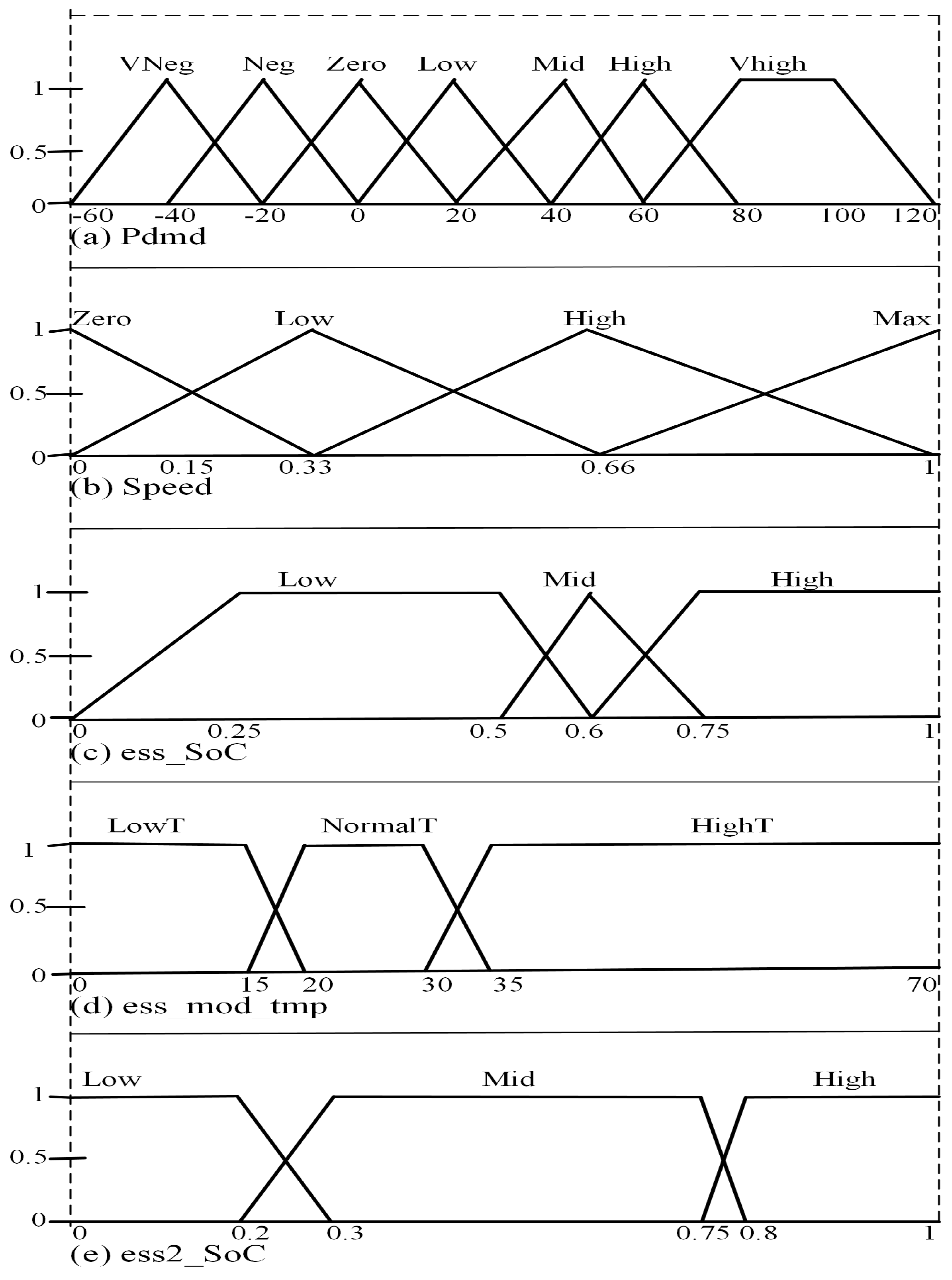
FLC is commonly applied in complex systems characterized by significant uncertainty. Its key advantage lies in its independence from a mathematical model or prior system knowledge. The FLC is utilized for allocating power demand to energy storage devices in the HESS. It operates based on the if–then rule, which comprises three stages: fuzzification, fuzzy inference system (FIS) engine, and defuzzification. The fuzzification stage converts the crisp inputs from numerical values into linguistic fuzzy variables, and a membership function is applied to assign a degree of membership to numerical data for various linguistic variables. The FIS defines the IF–THEN rules that link the inputs to the output, while defuzzification involves converting linguistic variables of the output into numerical values using a defuzzification method such as weighted sum, weighted average, or centroid. Sugeno-type FIS is adopted with five inputs: power demand ( P d m d ), normalized speed, battery SOC (ess_SOC), battery temperature (ess_mod_temp), and UC SOC (ess2_SOC). The membership functions of the input variables are depicted in Figure 2, while the output membership functions are linear, which are the power distribution factor (K): K b a t and K u c for battery and UC, respectively. The battery’s workload is limited to providing average power to mitigate the strain on it when there is a high demand for power, whereas the UC is responsible for meeting peak power requirements and recuperating energy through regeneration. The power allocation follows the set of equations expressed in (14). According to (14), the percentage of power output by the LIB and UC is not fixed but follows the dynamic operation of the drive cycle. However, the power supply by both energy storage devices, which is essentially determined by the power distribution factor (Kbat and Kuc, must meet the power demand of the vehicle.
P d m d = P b a t + P u c
P b a t = P d m d × K b a t
P u c = P d m d × K u c
K b a t + K u c = 1

3.2. Particle Swarm Optimization

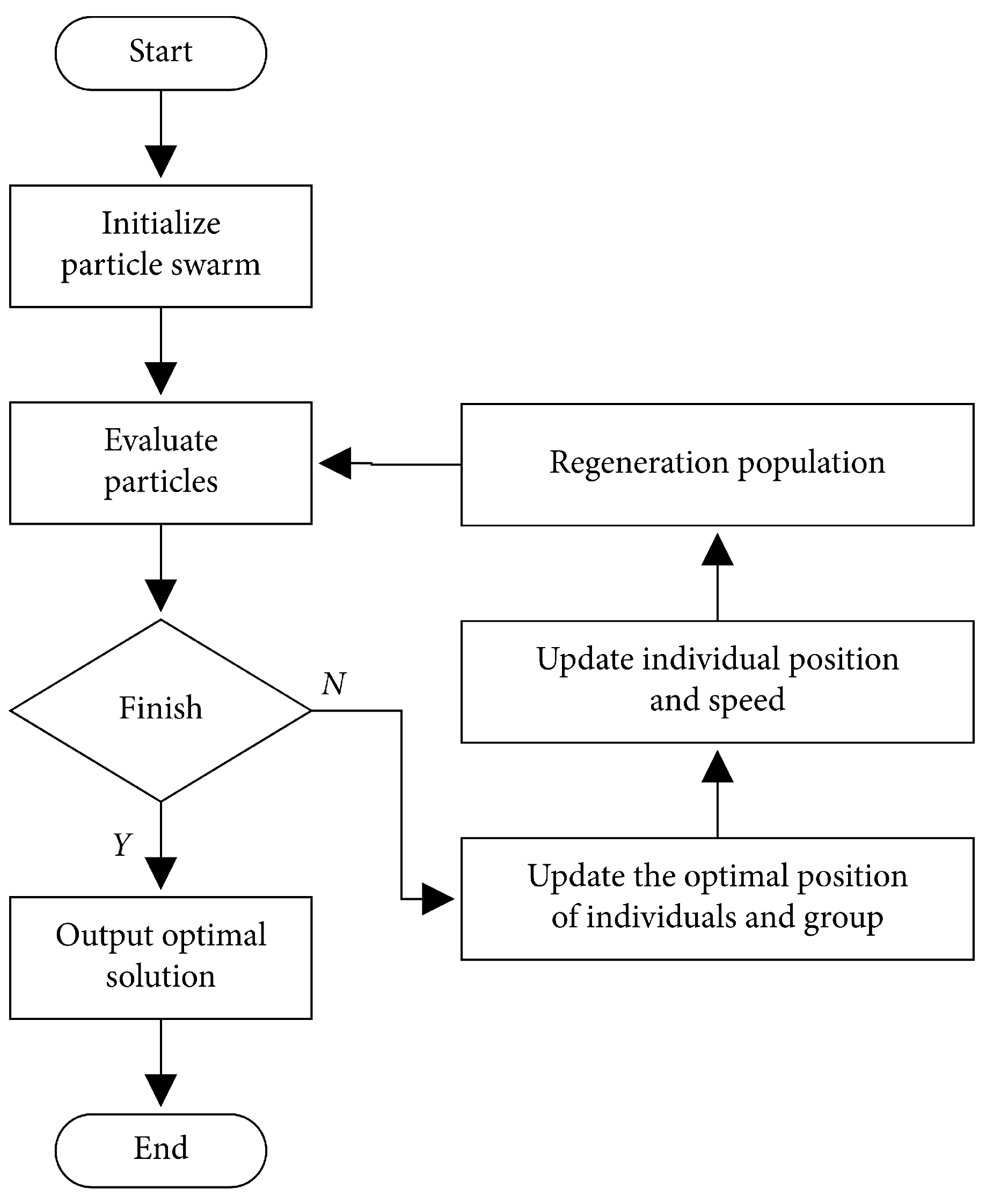
PSO is an iterative search algorithm that uses particles to explore a search space. Each particle represents a candidate solution and moves based on its current position and velocity, which are updated according to personal and global bests of the entire swarm, which guide the particles towards the optimal solution. The velocity of a particle is influenced by both its own experience (cognitive factor) and its neighbor’s experience (social factor). Typically, when searching a target space with d dimensions, a population of n particles is created. The position and velocity of particle (i) are represented in d-dimensional vectors, as in (18) and (19), while the optimal positions sought by the ith particle and the whole swarm are the individual extremum and global extremum, as expressed in Equations (20) and (21) [27].
X i = ( x i 1 , x i 2 , x i 3 , , x i D ) , i = 1 , 2 , 3 , , n
V i = ( v i 1 , v i 2 , v i 3 , , v i D ) , i = 1 , 2 , 3 , , n
P b = ( p i 1 , p i 2 , p i 3 , , p i D ) , i = 1 , 2 , 3 , , n .
G b = ( p g 1 , p g 2 , p g 3 , , p g D ) , i = 1 , 2 , 3 , , n .
V i d = ω v i d + c 1 · r a n d ( 0 , 1 ) · ( P i d X i d ) + c 2 · r a n d ( 0 , 1 ) · ( P g d X i d )
x i d = x i d + v i d
Equation (22) explains how the velocity vector of the particle is updated, and it involves three terms:
  • The first term, ω v i d , is the inertia term, which allows the particle to maintain its current direction of movement.
  • The cognitive term, represented by c 1 · rand ( 0 , 1 ) · ( p i d x i d ) in Equation (22), is influenced by the particle’s individual best location and encourages it to move towards that position.
  • The third term is the social term, denoted by c 2 · rand ( 0 , 1 ) · ( p g d x i d ) , which is affected by the group’s global best location. This term influences the particle to move towards the global best position.
c 1 and c 2 are acceleration coefficients that control the influence of the cognitive and social terms on the particle’s movement. rand ( 0 , 1 ) represents a random number between 0 and 1. Figure 3 portrays the workflow of the PSO algorithm. Equation (23) represents the update of the particle’s position in the search space. It simply adds the updated velocity to the current position.

3.3. Optimization of FLC with PSO Considering Battery Temperature Effect

Despite the expertise of a specialist in designing FLC rules, the FLC may not function optimally. Hence, PSO can serve as an intelligent search engine to optimize the FLC parameters without the need for exhaustive trial and error methods by a control engineer. The PSO optimization of FLC is achieved by considering the battery’s temperature as the cost function of the optimization problem. The objective is to minimize battery degradation in order to extend its lifespan. FLC performance depends on the weights of the crisp output, as depicted in Equation (24).
i = 1 n w i z i
where z i represents the crisp output of each rule and w i denotes the weight of the ith rule of the fuzzy logic system. However, due to the involvement of a large number of decision variables, the arbitrary selection of rule weights may lead to the inefficient operation of the dual energy storage devices. To address this issue, this paper employs PSO to turn the weights of the FLC using the cost function defined in (25).
J = t = 0 t end T d t
The equation J represents the objective to be minimized, where J is the cost function and T is the temperature, while the definite integral ranges from 0 s to t end , which is the end of the simulation. Among all inputs to the FLC, the temperature of the battery is selected as the PSO cost function due to LIBs’ increased temperature sensitivity compared to UC. The FLC is designed to maintain moderate battery temperature at low and high temperatures to prevent an increase in internal resistance and thermal runaway, respectively. Since the UC is rarely affected by temperature, power demand is channeled to it during low- and high-temperature conditions. Implementation of the FLC optimization structure in Figure 4 is achieved by following the following steps:
  • Initialize the algorithm by setting the number of iterations to 38, the number of particles to 16, the maximum velocity to 0.5, and the minimum velocity to −0.5.
  • Generate particles with random positions and velocities within the defined search space.
  • Simulate the EV model from the MATLAB script containing the PSO algorithm.
  • Evaluate the fitness of individual particles by applying the fitness function.
  • Update the particle position and velocity based on the PSO algorithm. The position update is based on the global and local best positions found so far, while the velocity update is based on the current position and the previous velocity.
  • Evaluate the fitness of the new particles and update the global and local best positions.
  • Repeat steps 5 and 6 until a stopping criterion is met, such as the maximum number of iterations or when the desired optimal fitness value is obtained.
  • Write the global best particle position as the weights to fuzzy rule sets.
In Appendix A and Appendix B, the details of the fuzzy logic controller including the parameter values, rules, and optimized weights are presented to provide clarity to the reader.

4. Results and Analysis

This section introduces the simulation platform and explains the process of adjusting parameter values. It presents the simulation results of the unoptimized and optimized FLC EMSs, and provides a comparison between the two, demonstrating the success of the proposed strategy in minimizing battery degradation through the optimization of the LIB temperature.

4.1. Platform

The complicated nature of computing parameters for simulating a HESS composed of LIB and UC necessitated the utilization of ADVISOR. ADVISOR is an open-source software which operates within MATLAB/Simulink environment. It is a registered trademark of the Alliance for Sustainable Energy, LLC, the manager and operator of the National Renewable Energy Laboratory (NREL) for the United States of America Department of Energy. The canonical version number 2003-00-r0116 is used for the rapid analysis of the performance of the proposed energy management strategy of the hybrid energy system. Simulating this hybrid energy storage system in it presents a practical approach to test the proposed EMS. In this paper, GM EV1 embedded within ADVISOR is used with all corresponding parameter values, except for the ESS, which was replaced with LIB-UC HESS. Table 3 lists the values of the different variables of the HESS. In order to guarantee sufficient space for swift charging and discharging of the UC, its initial SOC (ess2_SOC) is set to 90%, while ess_SOC is established at 80%. The UDDS drive cycle is employed as the driving cycle in the simulation.

4.2. Simulation Results of Unoptimized EMS

In this case study, the GM EV1 is simulated without the FLC being optimized. According to Figure 5a, the HESS delivers the necessary power to the electric motor to propel the vehicle. However, this comes at the cost of battery lifespan as the battery experiences significant current fluctuations, peaking at 240.3A, as illustrated in Figure 6c. The battery pack temperature is 31 °C due to these current spikes, whereas the temperature of UC, as shown in Figure 6b, is 20.1 °C. Figure 6d indicates that the Depth of Discharge (DoD) of the battery is 30.9%, while that of UC is 36%. SoC calculation of the UC is based on its voltage; hence, the voltage in Figure 6e and SOC in Figure 6f for the UC exhibits a strikingly similar pattern. Because the UC is assigned to supply peak power as well as receive regenerative power, its fluctuation is more than that of the battery, as shown in Figure 6e.

4.3. Simulation Results of Optimized EMS

In this scenario, the FLC is optimized using PSO and tested in the GM EV1. Figure 6a indicates that the HESS efficiently supplies the required power to the electric motor, while the UC retrieves the regeneration energy through the assistance of the EMS. Figure 6b shows the effect of the optimization in reducing the battery’s temperature to 25 °C, which leads to only four occurrences where the battery current exceeds100A, as depicted in Figure 6c, with a maximum current of 116.9A for the battery, and 66.3A for the UC. The UC compensates the constrained output power of the battery caused by optimization in order to fulfill the driving profile of the vehicle. As a result, the DoD of the UC and battery at the end of the trip are 47% and 26% for the UC and battery, as Figure 6d portrays, indicating improved efficiency and longer battery life. Figure 6e depicts a voltage drop of 11% for the battery, and the UC voltage decreases by 52% at the end of the trip. SoC variation of the UC follows the same trend as its voltage due to their direct relationship.

4.4. Comparison of Optimized and Unoptimized EMSs

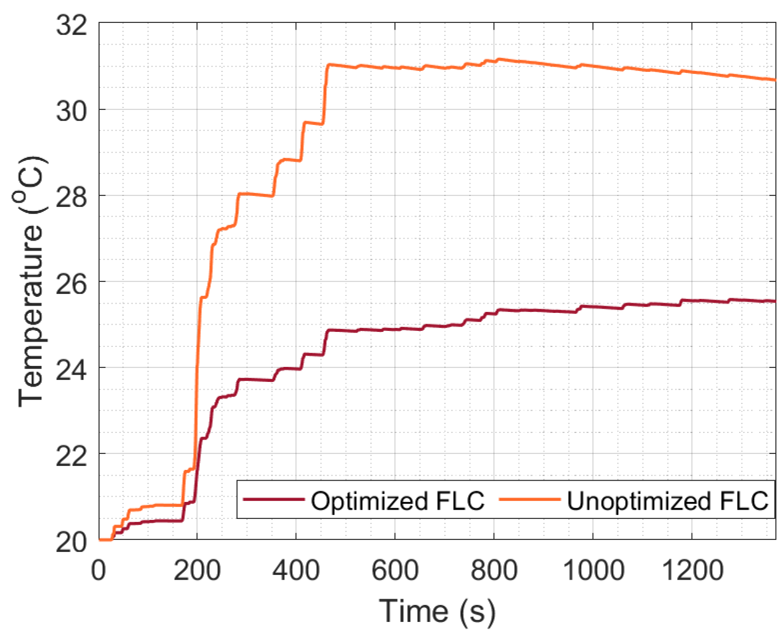
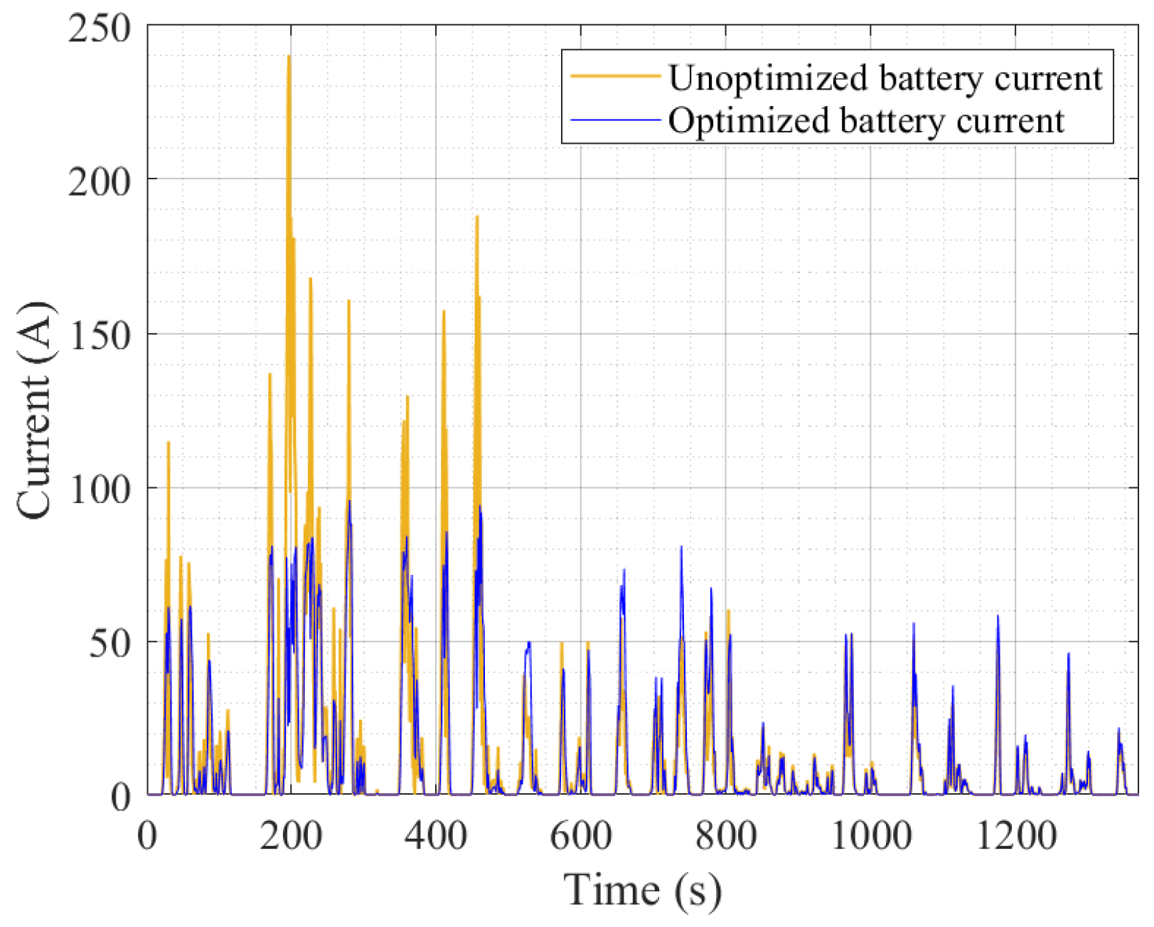
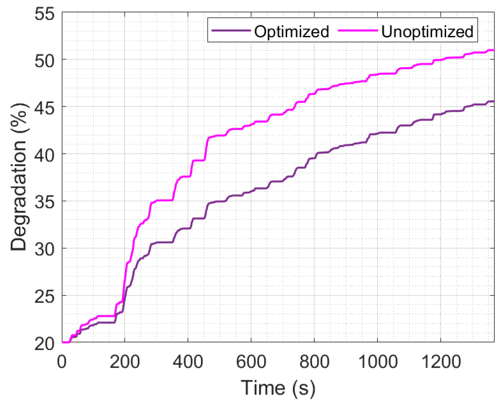
This section compares simulation results of battery pack variables obtained from optimized and unoptimized FLC EMSs. The unoptimized FLC led to a higher battery temperature, reaching 31 °C, while the optimized EMS resulted in a temperature of only 25.5 °C, representing an 18% reduction, as depicted in Figure 7. Reduction in the battery’s temperature ensures safe operation and avoidance of fire incidence occasioned by thermal runaway. Low temperatures impair LIBs’ performance, capacity, and lifespan. Conversely, high temperatures accelerate battery degradation, with risks of thermal runaways, especially during high-rate discharge. Hence, a moderate temperature between 15 °C and 25 °C is suitable for optimal performance of the battery in operation. Furthermore, the use of unoptimized FLC EMS led to a significant battery current magnitude, with a peak of 240 A. In contrast, the optimized FLC EMS reduced this by 51%, as Figure 8 reveals; this relieves the battery’s high current stress, which lengthens its lifespan. Figure 9 depicts the degradation of the battery as a measure of its capacity fade. It shows that the battery’s capacity decreases by 50.9% at the completion of the driving period in the unoptimized scenario and 45.5% in the optimized. This represents 5.4% capacity saved, leading to longer life and reduced need for charging and replacement. Table 4 provides a brief summary of the unoptimized and optimized EMSs for selected battery variables.

5. Conclusions

In conclusion, a particle swarm-optimized fuzzy logic energy management of a LIB-UC hybrid storage system for an EV was investigated. First, the GM EV1 power demand based on the UDDS driving cycle was extracted from the single LIB energy source. Subsequently, considering the EV’s operational characteristics and power demand, fuzzy logic rules were developed to distribute the required power between the LIB and UC simultaneously. Then, to address the problem of battery degradation due to large current fluctuation, the PSO was used to optimize the fuzzy logic weights, taking into consideration the battery’s operating temperature as a cost function. The performance of the proposed EMS was assessed by comparing it with an unoptimized FLC. Simulation results indicated that the battery’s temperature was reduced from the initial temperature of 31 °C to 25.5 °C in the optimized strategy. This led to a significant 51% reduction in peak current and a 5.4% improvement in capacity fade/degradation. These findings demonstrate that the proposed EMS is efficient in splitting the power request from the drivetrain and minimizing degradation, thereby ensuring safe battery pack operation, reducing the risk of thermal runaway, minimizing battery current stress, and increasing the battery’s lifespan. Overall, while the proposed particle swarm-optimized fuzzy logic control of the hybrid LIB-UC energy storage system offers numerous advantages in terms of efficient energy management, dynamic adaptation, and temperature-aware optimization, it also presents challenges such as oversizing each energy storage device and lack of adaptability to real-time driving data. These challenges will be addressed in future studies to further improve the proposed energy management strategy for electric vehicles.

Author Contributions

Conceptualization, J.O. and M.A.; methodology, J.O., M.A. and H.C.; writing—original draft preparation, J.O. and M.A.; writing—review and editing, J.O., M.A. and H.C.; visualization, J.O., M.A. and H.C.; supervision, H.C.; project administration, M.A. and H.C.; funding acquisition, H.C. All authors have read and agreed to the published version of the manuscript.

Funding

This research received no external funding.

Data Availability Statement

No new data were created or analyzed in this study. The original contributions presented in the study are included in the article, further inquiries can be directed to the corresponding author.

Conflicts of Interest

The authors declare no conflict of interest.

Appendix A. Fuzzy Logic Parameter Values

  • [System]
  • Name = fisEV_iter30
  • Type = sugeno
  • Version = 2.0
  • NumInputs = 5
  • NumOutputs = 2
  • NumRules = 37
  • AndMethod = prod
  • OrMethod = probor
  • ImpMethod = prod
  • AggMethod = sum
  • DefuzzMethod = wtsum
  • [Input1]
  • Name = Pdmd
  • Range = [−60 120]
  • NumMFs = 7
  • MF1 = ‘VNeg’:‘trimf’, [−60 −40 −20]
  • MF2 = ‘Neg’:‘trimf’, [−40 −20 0]
  • MF3 = ‘Zero’:‘trimf’, [−20 0 20]
  • MF4 = ‘Low’:‘trimf’, [0 20 40]
  • MF5 = ‘Mid’:‘trimf’, [20 40 60]
  • MF6 = ‘High’:‘trimf’, [40 60 80]
  • MF7 = ‘Vhigh’:‘trapmf’, [60 80 100 120]
  • [Input2]
  • Name = ‘speed2
  • Range = [0 1]
  • NumMFs = 4
  • MF1 = ‘zero’:‘trimf’, [−0.33 0 0.33]
  • MF2 = ‘low’:‘trimf’, [0 0.33 0.6667]
  • MF3 = ‘high’:‘trimf’, [0.33 0.6667 1]
  • MF4 = ‘max’:‘trimf’, [0.6667 1 1.32]
  • [Input3]
  • Name = ess_SOC
  • Range = [0 1]
  • NumMFs = 3
  • MF1 = ‘low’:‘trapmf’, [0 0.25 0.5 0.6]
  • MF2 = ‘mid’:‘trimf’, [0.5 0.6 0.75]
  • MF3 = ‘high’:‘trapmf’, [0.6 0.75 1 1.8]
  • [Input4]
  • Name = ‘ess_mod_tmp’
  • Range=[0 70]
  • NumMFs=3
  • MF1 = ‘LowT’:‘trapmf’, [−31.5 −10 15 20]
  • MF2 = ‘NormalT’:‘trapmf’, [15 20 30 35]
  • MF3 = ‘HightT’:‘trapmf’, [30 35 101.5 101.5]
  • [Input5]
  • Name=ess2_SOC
  • Range=[0 0.95]
  • NumMFs=3
  • MF1 = ‘low’:‘trapmf’, [−0.3895 −0.0855 0.2 0.3]
  • MF2 = ‘mid’:‘trapmf’, [0.2 0.3 0.75 0.8]
  • MF3 = ‘high’:‘trapmf’, [0.75 0.8 0.95 1.377]
  • [Output1]
  • Name = ‘Pbat’
  • Range=[0 1]
  • NumMFs=9
  • MF1 = ‘k1’:‘constant’, [0]
  • MF2 = ‘k2’:‘constant’, [0.2]
  • MF3 = ‘k3’:‘constant’, [0.3]
  • MF4 = ‘k4’:‘constant’, [0.4]
  • MF5 = ‘k5’:‘constant’, [0.5]
  • MF6 = ‘k6’:‘constant’, [0.6]
  • MF7 = ‘k7’:‘constant’, [0.7]
  • MF8 = ‘k8’:‘constant’, [0.8]
  • MF9 = ‘k9’:‘constant’, [1]
  • [Output2]
  • Name = ‘Puc’
  • Range=[0 1]
  • NumMFs=9
  • MF1 = ‘k1’:‘constant’, [0]
  • MF2 = ‘k2’:‘constant’, [0.2]
  • MF3 = ‘k3’:‘constant’, [0.3]
  • MF4 = ‘k4’:‘constant’, [0.4]
  • MF5 = ‘k5’:‘constant’, [0.5]
  • MF6 = ‘k6’:‘constant’, [0.6]
  • MF7 = ‘k7’:‘constant’, [0.7]
  • MF8 = ‘k8’:‘constant’, [0.8]
  • MF9 = ‘k9’:‘constant’, [1]

Appendix B. Fuzzy Logic RULES

  • If (Pdmd is Low) and (ess_SOC is mid) and (ess2_SOC is low) then (Pbat is k9)(Puc is k1) (0.84454).
  • If (Pdmd is low) and (ess_SOC is high) and (ess2_SOC is low) then (Pbat is k9)(Puc is k1)(0.75).
  • If (Pdmd is Mid) and (ess_SOC is mid) and (ess2_SOC is low) then (Pbat is k9)(Puc is k1)(0.5).
  • If (Pdmd is Mid) and (ess_SOC is high) and (ess2_SOC is low) then (Pbat is k9)(Puc is k1)(0.25).
  • If (Pdmd is Low) and (ess_SOC is mid) and (ess2_SOC is mid) then (Pbat is k9)(Puc is k1)(0.0012992).
  • If (Pdmd is Low) and (ess_SOC is high) and (ess2_SOC is mid) then (Pbat is k9)(Puc is k1)(0.84458).
  • If (Pdmd is Mid) and (ess_SOC is mid) and (ess2_S0C is mid) then (Pbat is k9)(Puc is k1) (0.75).
  • If (Pdmd is Mid) and (ess_SOC is high) and (ess2_SOC is mid) then (Pbat is k9)(Puc is k1) (0.5).
  • If (Pdmd is Low) and (ess_SOC is mid) and (ess2_SOC is high) then (Pbat is k9)(Puc is k1)(0.25).
  • If (Pdmd is Low) and (ess_SOC is high) and (ess2_SOC is high) then (Pbat is k9)(Puc is k1)(0.0012992).
  • If (Pdmd is Mid) and (ess_SOC is mid) and (ess2_SOC is high) then (Pbat is k9)(Puc is k1)(0.0012992).
  • If (Pdmd is Mid) and (ess_SOC is high) and (ess2_SOC is high) then (Pbat is k9)(Puc is k1)(0.0012992).
  • If (Pdmd is High) and (ess_SOC is mid) and (ess2_SOC is low) then (Pbat is k9)(Puc is k1)(0.0012992).
  • If (Pdmd is High) and (ess_SOC is low) and (ess2_SOC is low) then (Pbat is k9)(Puc is k1)(0.36481).
  • If (Pdmd is High) and (ess_SOC is high) and (ess2_SOC is low) then (Pbat is k9)(Puc is k1)(0.36481).
  • If (Pdmd is Vhigh) and (ess_SOC is mid) and (ess2_SOC is low) then (Pbat is k9)(Puc is k1) (0.36481).
  • If (Pdmd is Vhigh) and (ess_SOC is high) and (ess2_SOC is low) then (Pbat is k9)(Puc is k1)(0.034294).
  • If (Pdmd is High) and (ess2_SOC is mid) then (Pbat is k1)(Puc is k9)(1).
  • If (Pdmd is Vhigh) and (ess2_SOC is mid) then (Pbat is k1)(Puc is k9)(1).
  • If (Pdmd is High) and (ess2_SOC is high) then (Pbat is k1)(Puc is k9)(1).
  • If (Pdmd is Vhigh) and (ess2_SOC is high) then (Pbat is k1)(Puc is k9)(1).
  • If (Pdmd is VNeg) and (ess2_SOC is low) then (Pbat is k1)(Puc is k9)(1).
  • If (Pdmd is Neg) and (ess2_SOC is low) then (Pbat is k1)(Puc is k9)(1).
  • If (Pdmd is Zero) and (ess2_SOC is low) then (Pbat is k1)(Puc is k9)(1).
  • If (Pdmd is VNeg) and (ess2_SOC is mid) then (Pbat is k1)(Puc is k9)(1).
  • If (Pdmd is Neg) and (ess2_SOC is mid) then (Pbat is k1)(Puc is k9).
  • If (Pdmd is Zero) and (ess2_SOC is mid) then (Pbat is k1)(Puc is k9)(1).
  • If (Pdmd is VNeg) and (ess2_SOC is high) then (Pbat is k1)(Puc is k9)(1).
  • If (Pdmd is Neg) and (ess2_SOC is high) then (Pbat is k1)(Puc is k9)(1).
  • If (Pdmd is Zero) and (ess2_SOC is high) then (Pbat is k1)(Puc is k9)(1).
  • If (Pdmd is High) and (speed2 is high) and (ess_SOC is low) and (ess_mod_tmp is NormalT) and (ess2_SOC is high) then (Pbat is k1)(Puc is k9)(1).
  • If (Pdmd is Low) and (speed2 is high) and (ess_SOC is high) and (ess_mod_tmp is NormalT) and (ess2_SOC is high) then (Pbat is k7)(Puc is K3)(1).
  • If (Pdmd is Low) and (speed2 is max) and (ess_SOC is high) and (ess_mod_tmp is NormalT) and (ess2_SOC is high) then (Pbat is k7)(Puc is k3)(1).
  • If (Pdmd is Low) and (ess_SOC is low) then (Pbat is k3)(Puc is k7)(1).
  • If (Pdmd is Mid) and (ess_SOC is low) then (Pbat is k1)(Puc is k9)(1).
  • If (Pdmd is High) and (ess_SOC is low) then (Pbat is k1)(Puc is k9)(1).
  • If (Pdmd is Vhigh) and (ess_SOC is low) then (Pbat is k1)(Puc is k9)(1).

References

  1. Kakouche, K.; Oubelaid, A.; Mezani, S.; Rekioua, T.; Bajaj, M.; Jurado, F.; Kamel, S. Energy Management Strategy of Dual-Source Electric Vehicles Based on Fuzzy Logic Control Considering Driving Cycles. In Proceedings of the 2023 IEEE 5th Global Power, Energy and Communication Conference, GPECOM 2023, Cappadocia, Turkiye, 14–16 June 2023; Institute of Electrical and Electronics Engineers Inc.: Piscataway, NJ, USA, 2023; pp. 92–97. [Google Scholar] [CrossRef]
  2. Khalili, S.; Rantanen, E.; Bogdanov, D.; Breyer, C. Global transportation demand development with impacts on the energy demand and greenhouse gas emissions in a climate-constrained world. Energies 2019, 12, 3870. [Google Scholar] [CrossRef]
  3. Li, X.; He, F.; Zhang, G.; Huang, Q.; Zhou, D. Experiment and simulation for pouch battery with silica cooling plates and copper mesh based air cooling thermal management system. Appl. Therm. Eng. 2019, 146, 866–880. [Google Scholar] [CrossRef]
  4. Mehraban, A.; Ghanbari, T.; Farjah, E. AI-based Control of Storage Capacity in High Power Density Energy Storage Systems, Used in Electric Vehicles. IEEE Trans. Transp. Electrif. 2023, 10, 2293–2301. [Google Scholar] [CrossRef]
  5. Shen, Y.; Xie, J.; He, T.; Yao, L.; Xiao, Y. CEEMD-fuzzy Control Energy Management of Hybrid Energy Storage Systems in Electric Vehicles. IEEE Trans. Energy Convers. 2023, 39, 555–566. [Google Scholar] [CrossRef]
  6. Han, Y.; Li, J.; Wang, B. Event-Triggered Active Disturbance Rejection Control for Hybrid Energy Storage System in Electric Vehicle. IEEE Trans. Transp. Electrif. 2023, 9, 75–86. [Google Scholar] [CrossRef]
  7. Wasim, M.S.; Habib, S.; Amjad, M.; Bhatti, A.R.; Ahmed, E.M.; Qureshi, M.A. Battery-Ultracapacitor Hybrid Energy Storage System to Increase Battery Life Under Pulse Loads. IEEE Access 2022, 10, 62173–62182. [Google Scholar] [CrossRef]
  8. Rezaei, H.; Abdollahi, S.E.; Abdollahi, S.; Filizadeh, S. Energy managment strategies of battery-ultracapacitor hybrid storage systems for electric vehicles: Review, challenges, and future trends. J. Energy Storage 2022, 53, 105045. [Google Scholar] [CrossRef]
  9. Ren, G.; Wang, J.; Li, Y.; Zhang, G. Power distribution optimization of a fully active hybrid energy storage system configuration for vehicular applications. J. Ind. Inf. Integr. 2023, 33. [Google Scholar] [CrossRef]
  10. Zhang, L.; Hu, X.; Wang, Z.; Sun, F.; Deng, J.; Dorrell, D.G. Multiobjective Optimal Sizing of Hybrid Energy Storage System for Electric Vehicles. IEEE Trans. Veh. Technol. 2018, 67, 1027–1035. [Google Scholar] [CrossRef]
  11. Gunther, S.; Weber, L.; Bensmann, A.L.; Hanke-Rauschenbach, R. Structured Analysis and Review of Filter-Based Control Strategies for Hybrid Energy Storage Systems. IEEE Access 2022, 10, 126269–126284. [Google Scholar] [CrossRef]
  12. Yu, W.; Jin, Y.; Jiang, Z. Research on the Control Strategy of Hybrid Energy Storage System for Electric Bus. In Proceedings of the 2023 8th Asia Conference on Power and Electrical Engineering, ACPEE 2023, Tianjin, China, 14–16 April 2023; Institute of Electrical and Electronics Engineers Inc.: Piscataway, NJ, USA, 2023; pp. 843–847. [Google Scholar] [CrossRef]
  13. Yin, H.; Zhou, W.; Li, M.; Ma, C.; Zhao, C. An adaptive fuzzy logic-based energy management strategy on battery/ultracapacitor hybrid electric vehicles. IEEE Trans. Transp. Electrif. 2016, 2, 300–311. [Google Scholar] [CrossRef]
  14. Eckert, J.J.; Silva, L.C.D.A.; Dedini, F.G.; Correa, F.C. Electric Vehicle Powertrain and Fuzzy Control Multi-Objective Optimization, Considering Dual Hybrid Energy Storage Systems. IEEE Trans. Veh. Technol. 2020, 69, 3773–3782. [Google Scholar] [CrossRef]
  15. Mesbahi, T.; Rizoug, N.; Bartholomeüs, P.; Sadoun, R.; Khenfri, F.; Le Moigne, P. Optimal energy management for a Li-ion battery/supercapacitor hybrid energy storage system based on a particle swarm optimization incorporating nelder-mead simplex approach. IEEE Trans. Intell. Veh. 2017, 2, 99–110. [Google Scholar] [CrossRef]
  16. Lu, X.; Wang, H. Optimal Sizing and Energy Management for Cost-Effective PEV Hybrid Energy Storage Systems. IEEE Trans. Ind. Inform. 2020, 16, 3407–3416. [Google Scholar] [CrossRef]
  17. da Silva, S.F.; Eckert, J.J.; Corrêa, F.C.; Silva, F.L.; Silva, L.C.; Dedini, F.G. Dual HESS electric vehicle powertrain design and fuzzy control based on multi-objective optimization to increase driving range and battery life cycle. Appl. Energy 2022, 324, 119723. [Google Scholar] [CrossRef]
  18. Yu, S.; Lin, D.; Sun, Z.; He, D. Efficient model predictive control for real-time energy optimization of battery-supercapacitors in electric vehicles. Int. J. Energy Res. 2020, 44, 7495–7506. [Google Scholar] [CrossRef]
  19. Zhang, Q.; Wang, L.; Li, G.; Liu, Y. A real-time energy management control strategy for battery and supercapacitor hybrid energy storage systems of pure electric vehicles. J. Energy Storage 2020, 31, 101721. [Google Scholar] [CrossRef]
  20. Chen, Z.; Xiong, R.; Cao, J. Particle swarm optimization-based optimal power management of plug-in hybrid electric vehicles considering uncertain driving conditions. Energy 2016, 96, 197–208. [Google Scholar] [CrossRef]
  21. Seixas, L.D.; Tosso, H.G.; Correa, F.C.; Eckert, J. Particle swarm optimization of a fuzzy controlled hybrid energy storage system—HESS. In Proceedings of the 2020 IEEE Vehicle Power and Propulsion Conference, VPPC 2020, Gijon, Spain, 1–6 November 2020; Institute of Electrical and Electronics Engineers Inc.: Piscataway, NJ, USA, 2021; pp. 1–6. [Google Scholar] [CrossRef]
  22. Singirikonda, S.; Yeddula Pedda, O. Investigation on performance evaluation of electric vehicle batteries under different drive cycles. J. Energy Storage 2023, 63, 106966. [Google Scholar] [CrossRef]
  23. Barlow, T.J.; Latham, S.; Mccrae, I.S.; Boulter, P.G. A Reference Book of Driving Cycles for Use in the Measurement of Road Vehicle Emissions; TRL Published Project Report; TRL: Crowthorne, UK, 2009. [Google Scholar]
  24. Anthony, F.; Irwin. Motor Controller. Available online: https://adv-vehicle-sim.sourceforge.net/motor_controller.html (accessed on 4 March 2023).
  25. Ye, K.; Li, P.; Li, H. Optimization of Hybrid Energy Storage System Control Strategy for Pure Electric Vehicle Based on Typical Driving Cycle. Math. Probl. Eng. 2020, 2020, 1365195. [Google Scholar] [CrossRef]
  26. Zhu, T. Energy Management and Sizing of a Dual Energy Storage System for Electric Vehicles. Ph.D. Thesis, University of Southampton, Southampton, UK, 2021. [Google Scholar]
  27. Liang, J.J.; Suganthan, P.N. Dynamic multi-swarm particle swarm optimizer with local search. In Proceedings of the 2005 IEEE Congress on Evolutionary Computation, IEEE CEC 2005, Edinburgh, UK, 2–5 September 2005; Volume 1, pp. 522–528. [Google Scholar] [CrossRef]
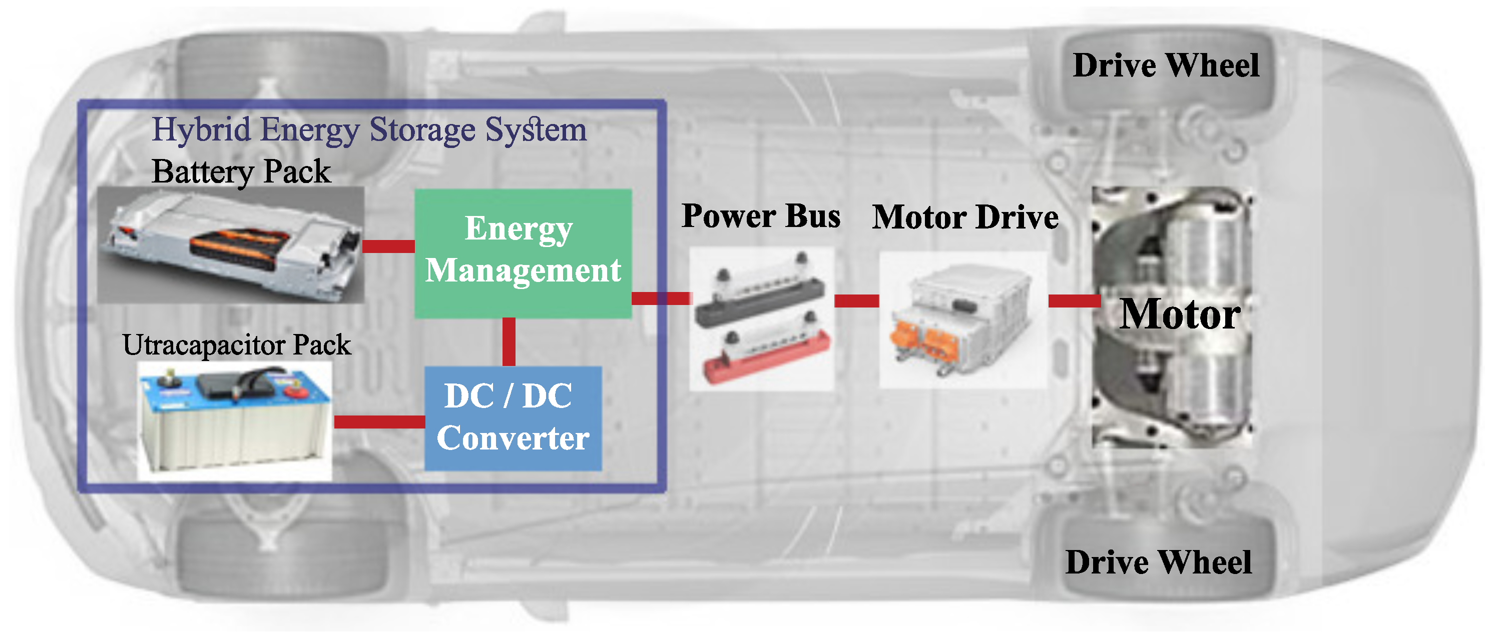
Figure 1. HESS architecture in the EV.
Energies 17 02163 g001
Figure 2. Fuzzy membership functions: (a) power demand (pdmd), (b) speed, (c) battery state of charge (ess_SoC), (d) battery temperature (ess_mod_tmp), and (e) UC state of charge (ess2_SoC).
Energies 17 02163 g002
Figure 3. Particle swarm optimization flowchart.
Energies 17 02163 g003
Figure 4. Optimized FLC structure.
Energies 17 02163 g004
Figure 5. Unoptimized EMS.
Energies 17 02163 g005
Figure 6. Optimized EMS.
Energies 17 02163 g006
Figure 7. Temperature difference between optimized and unoptimized EMSs.
Energies 17 02163 g007
Figure 8. Comparing current fluctuation of optimized and unoptimized EMSs.
Energies 17 02163 g008
Figure 9. Contrasting degradation of the battery in unoptimized and optimized scenarios.
Energies 17 02163 g009
Table 1. Vehicle specifications.
Vehicle Dynamics
ParameterValue
Frontal area, A (m2)2.0379
Air density, ρ (kg/m3)1.2
Drag coefficient, C d 0.19
Gravitational acceleration, g (m/s2)9.81
Total mass (kg)1487
Vehicle wheelbase (m)2.5121
Gear ratio10
Number of gears1
Rolling resistance coefficient, μ r r 0.0068
Table 2. Electric motor design parameters.
Traction Motor Drive
ParametersValue
Efficiency0.9098
Mass of motor (kg)91
Max. current (A)480
Max. voltage (V)120
Rated power (kW)75
Table 3. Battery–UC design parameters.
Parameters/ValuesBatteryUltracapacitor
Minimum cell voltage (V)20
Maximum cell voltage (V)3.92.5
Nominal voltage of pack (V)192175
Cell test temp. (degree Celsius)0–410–40
Nominal capacity6 Ah2500 F
Number of series modules18140
Number of parallel modules24
Table 4. Summary of results for the battery.
Battery VariableUnoptimized EMSOptimized EMS
Temperature31 °C25.5 °C
Peak current240 A116.3 A
Maximum power delivered38.3 kW21.1 kW
Capacity fade50.9%45.5%
Disclaimer/Publisher’s Note: The statements, opinions and data contained in all publications are solely those of the individual author(s) and contributor(s) and not of MDPI and/or the editor(s). MDPI and/or the editor(s) disclaim responsibility for any injury to people or property resulting from any ideas, methods, instructions or products referred to in the content.