
Analysis of the Efficiency of Burning Briquettes from Agricultural and Industrial Residues in a Layer
 , ,
, , 
Abstract
:1. Introduction
- -
- The uneven bulk density of the layer can be accompanied by different aerodynamic resistances both over the cross section and in the layer plane, changing not only the flow rate of particles but also the ratio of the supplied combustion air. As a result, combustion conditions change and, therefore, the quality of the whole combustion process changes.
- -
- Directly related to this problem is the instability of the height of the fuel layer, since changes in the air supply speed affect not only the height of the layer but also the stability of redox reactions.
- -
- The ratio of volatile matter release and the formation of coke residue depend on the percentage composition of the main components of the fuel briquette, and they affect all stages of combustion.
- -
2. Materials and Methods
- -
- Cleaning raw materials from foreign inclusions (glass, plastic, metal, etc.);
- -
- Drying raw materials in the open air to an air-dry state;
- -
- Grinding raw materials to a size of no more than three millimeters;
- -
- Preparing a homogeneous mixture from crushed raw materials;
- -
- Loading into the press and pressing fuel briquettes at a pressure of 25 MPa;
- -
- Drying the resulting fuel briquettes indoors to an air-dry state.
3. Results and Discussion
- λ—thermal conductivity coefficient of the material, kJ/(m·°C).
- ρ—material density, kg/m3.
- a = —thermal diffusivity coefficient, m2/s.
4. Conclusions and Future Research Directions
- -
- Experimental study of the influence of the thermophysical and thermal characteristics of briquettes on the combustion process.
- -
- Study of the influence of the design features of a firebox with a grate on the process of burning briquettes (with appropriate modernization of the stand).
Author Contributions
Funding
Data Availability Statement
Conflicts of Interest
References
- Nikiforov, A.; Kinzhibekova, A.; Prikhodko, E.; Karmanov, A.; Nurkina, S. Analysis of the Characteristics of Bio-Coal Briquettes from Agricultural and Coal Industry Waste. Energies 2023, 16, 3527. [Google Scholar] [CrossRef]
- Nurkina, S.; Kinzhibekova, A.; Prikhodko, E. Research and analysis of characteristics of fuel from organic and industrial waste. EUREKA Phys. Eng. 2022, 5, 43–54. [Google Scholar] [CrossRef]
- Akpenpuun, T.D.; Salau, R.A.; Adebayo, A.O.; Adebayo, O.; Salawu, J.; Durotoye, M. Physical and combustible properties of briquettes produced from a combination of groundnut shell, rice husk, sawdust and wastepaper using starch as a binder. J. Appl. Sci. Environ. Manag. 2020, 24, 171–177. [Google Scholar] [CrossRef]
- Kpelou, P.; Kongnine, D.; Kombate, S.; Mouzou, E.; Napo, K. Energy Efficiency of Briquettes Derived from Three Agricultural Waste’s Charcoal Using Two Organic Binders. J. Sustain. Bioenergy Syst. 2019, 9, 79–89. [Google Scholar] [CrossRef]
- Ana, G.R.; Fabunmi, V.T. Energy Efficiency Evaluation from the Combustion of Selected Briquettes-Derived Agro-Waste with Paper and Starch Binders. Int. J. Sustain. Green Energy 2016, 5, 71–79. [Google Scholar] [CrossRef]
- Abimbola, A.I.; Rapheal, I.A.; Musa, A. Combustion Quality Evaluation of Briquettes Produced from Sesame Hull as Source of Sustainable Energy. Asian J. Energy Transform. Conserv. 2020, 4, 30–39. [Google Scholar] [CrossRef]
- Kumar, G.S.; Rao, C.J.; Sreeramulu, D.; Madhavi, S.K. Evaluation of boiler efficiency of bio briquettes by indirect method. Int. J. Mech. Eng. Technol. (IJMET) 2016, 7, 624–633. [Google Scholar]
- Yashpal, A.; Kumar, D.; Anand, E.T. Efficiency Performance Analysis of Briquette & FO Boiler of Beverage Industry. Int. J. Res. Appl. Sci. Eng. Technol. 2021, 9, 284–290. [Google Scholar] [CrossRef]
- IS 8753; Code for Acceptance Tests on Stationary Steam Generators of the Power Station Type. Indian Standards Institution: New Delhi, India, 1977.
- Balakrishna, D.; Javaregowda, M.B.; Ramanaik, H.S.; Kuvenja, S.K. Comparative analysis of boiler efficiency between commercial sawdust briquettes and biomass briquettes. Proc. AIP Conf. Proc. 2020, 2236, 030010. [Google Scholar] [CrossRef]
- Khzmalyan, D.M.; Kagan, Y.A. Combustion Theory and Combustion Devices; Energy: Moscow, Russia, 1976; p. 484. (In Russian) [Google Scholar]
- Érces, N.; Kajtár, L. Operational Testing of a Solid Fuel Boiler with Different Fuels. Energies 2021, 14, 2966. [Google Scholar] [CrossRef]
- Goerner, K. Waste Incineration European State of the Art and New Developments. IFRF Combust. J. 2003, 32, 200303. Available online: https://ifrf.net/research/archive/waste-incineration-european-state-of-the-art-and-new-developments/ (accessed on 12 December 2023).
- Morrow, R.S. Renewable Fuel Grate firing Combustion Technology—The European Experience; Detroit Stoker Company: Monroe, MI, USA, 2005. [Google Scholar]
- Spliethoff, H.; Hein, K.R.G. Effect of co-combustion of biomass on emissions in pulverized fuel furnaces. Fuel Process. Technol. 1998, 54, 189–205. [Google Scholar] [CrossRef]
- Jenkins, B.M.; Baxter, L.L.; Miles, T.R., Jr.; Miles, T.R. Combustion properties of biomass. Fuel Process. Technol. 1998, 54, 17–46. [Google Scholar] [CrossRef]
- Subramanian, A.K.; Marwaha, Y. Use of bagasse and other biomass fuels in high pressure travelling grate boilers. Int. Sugar J. 2006, 108, 6–9. Available online: https://www.researchgate.net/publication/284672399_Use_of_bagasse_and_other_biomass_fuels_in_high_pressure_Travelling_Grate_boilers (accessed on 5 January 2024).
- Nikiforov, A.; Prikhodko, E.; Kinzhibekova, A.; Nurkina, S. Modeling the influence of the characteristics of renewable organic materials on the energy performance of the boiler. In Proceedings of the IOP Conference Series: Materials Science and Engineering, Borovets, Bulgaria, 26–29 November 2020; IOP Publishing: Bristol, UK, 2020; Volume 1032, p. 012035. [Google Scholar] [CrossRef]
- Werther, J.; Ogada, T. Sewage sludge combustion. Progr. Energy Combust. Sci. 1999, 25, 55–116. [Google Scholar] [CrossRef]
- Sami, M.; Annamalai, K.; Wooldridge, M. Co-firing of coal and biomass fuel blends. Progr. Energy Combust. Sci. 2001, 27, 171–214. [Google Scholar] [CrossRef]
- Thunman, H.; Leckner, B. Ignition and propagation of a reaction front in cross-current bed combustion of wet biofuels. Fuel 2001, 80, 473–481. [Google Scholar] [CrossRef]
- Nikiforov, A.S.; Prikhodko, E.V.; Kinzhibekova, A.K.; Nurkina, S.M. Study of strength characteristics of fuel briquettes from organic waste. In Proceedings of the AIP Conference Proceedings, Tomsk, Russia, 9–11 October 2019; Volume 2212, p. 020044. [Google Scholar] [CrossRef]
- Wang, Y.; Chen, X.; Xu, L.; Ma, M.; Huang, X.; Han, F.; Zhou, Y.; Du, C.; Da, Y.; Deng, L. Computational Particle Fluid Dynamics Simulation on Combustion Characteristics of Blended Fuels of Coal, Biomass, and Oil Sludge in a 130th−1 Circulating Fluidized Bed Boiler. Energies 2024, 17, 149. [Google Scholar] [CrossRef]
- Kraszkiewicz, A.; Przywara, A.; Anifantis, A.S. Impact of Ignition Technique on Pollutants Emission during the Combustion of Selected Solid Biofuels. Energies 2020, 13, 2664. [Google Scholar] [CrossRef]
- Kraszkiewicz, A.; Przywara, A.; Parafiniuk, S. Emission of Nitric Oxideduring the Combustion of Various Forms of Solid Biofuels in a Low-Power Heating Device. Energies 2022, 15, 5960. [Google Scholar] [CrossRef]
- Ozgen, S.; Cernuschi, S.; Caserini, S. An overview of nitrogen oxides emissions from biomass combustion for domestic heat production. Renew. Sustain. Energy Rev. 2021, 135, 110113. [Google Scholar] [CrossRef]
- Huang, H.; Gao, Y.; Chen, H.; Wu, Y.; Wang, J.; Yu, C.; Li, J.; Zou, C. Biomass briquette fuel, boiler types and pollutant emissions of industrial biomass boiler: A review. Particuology 2023, 77, 79–90. [Google Scholar] [CrossRef]
- Yue, T.; Tong, Y.; Gao, J.; Yuan, Y.; Wang, L.; Wei, H. High-precision spatial-temporal variations and future perspectives of multiple air pollutant emissions from Chinese biomass-fired industrial boilers. Sci. Total Environ. 2024, 907, 167982. [Google Scholar] [CrossRef] [PubMed]
- Pilusa, T.; Huberts, R.; Muzenda, E. Emissions analysis from combustion of ecofuel briquettes for domestic application. J. Energy South. Afr. 2013, 24, 30–36. [Google Scholar] [CrossRef]
- Wielgosiński, G.; Łechtańska, P.; Namiecińska, O. Emission of some pollutants from biomass combustion in comparison to hard coal combustion. J. Energy Inst. 2017, 90, 787–796. [Google Scholar] [CrossRef]
- ACTM E 230/E 230Ma:2023; Standard Specification and Temperature-Electromotive Force (EMF) Tables for Standardized Thermocouples. ASTM International: Washington, DC, USA, 2023.
- Knorre, G.F. Furnace Processes [Toposhnye Prosesy], 2nd ed.; Gosenergoizdat Publ: Moscow, Russia, 1959; p. 396. (In Russian) [Google Scholar]
- Panteleev, A.V.; Yakimova, A.S.; Bosov, A.V. Ordinary Differential Equations in Examples and Problems; Higher School: Moscow, Russia, 2001; p. 376. (In Russian) [Google Scholar]
- Aramanovich, I.G.; Lunts, G.L.; Elsgolts, L.E. Functions of a Complex Variable. Operational Calculus. Theory of Stability; Nauka: Moscow, Russia, 1968; 416p. (In Russian) [Google Scholar]


| Briquette Composition | Compound (As Received), % | Lower Calorific Value, kJ/kg | ||||||
|---|---|---|---|---|---|---|---|---|
| W | A | S | C | H | N | O | ||
| 70% sunflower husks and 30% coke breeze | 3.91 | 3.42 | 0.17 | 59.90 | 6.66 | 0.45 | 25.49 | 23,265 |
| 30% sunflower husks and 70% leaves | 3.91 | 2.82 | 0.05 | 48.29 | 8.10 | 0.75 | 36.08 | 20,617 |
| Briquette Composition | 30% Sunflower Husks and 70% Leaves | |||||
|---|---|---|---|---|---|---|
| Composition of the Combustion Products | Confidence Interval | |||||
| Test Number | 1 | 2 | 3 | 4 | 5 | |
| O2, % | 16.340 | 16.160 | 14.280 | 16.270 | 15.710 | 0.893 |
| CO, % | 0.882 | 1.224 | 2.176 | 0.898 | 1.815 | 0.599 |
| SO2, % | 0 | 0 | 0 | 0 | 0 | 0 |
| NOx, % | 0.054 | 0.074 | 0.121 | 0.105 | 0.093 | 0.027 |
| CO2, % | 4.370 | 4.440 | 6.280 | 4.160 | 5.070 | 0.896 |
| H2, % | 0.152 | 0.167 | 0.374 | 0.166 | 0.211 | 0.096 |
| Temperature values (°C) | ||||||
| tflue gas | 299.0 | 279.0 | 279.6 | 289.0 | 275.2 | 10.022 |
| tambient air | 18.6 | 17.5 | 17.0 | 14.1 | 18.1 | 1.833 |
| Maximum content of CO and SO2 in dry combustion products at α = 1 | ||||||
| RO2max | 0.882 | 1.224 | 2.176 | 0.898 | 1.648 | 0.374 |
| Calculation results | ||||||
| Value h | 0.1679 | 0.2161 | 0.2573 | 0.1775 | 0.2237 | 0.0378 |
| Heat loss from chemical under-burning q3, % | 0.51 | 0.89 | 1.94 | 0.56 | 1.25 | 0.36 |
| Combustion efficiency, % | 53.97 | 58.67 | 70.11 | 55.54 | 62.25 | 3.81 |
| Briquette Composition | 70% Sunflower Husks and 30% Coke Breeze | |||||
|---|---|---|---|---|---|---|
| Composition of the Combustion Products | Confidence Interval | |||||
| Test Number | 1 | 2 | 3 | 4 | 5 | |
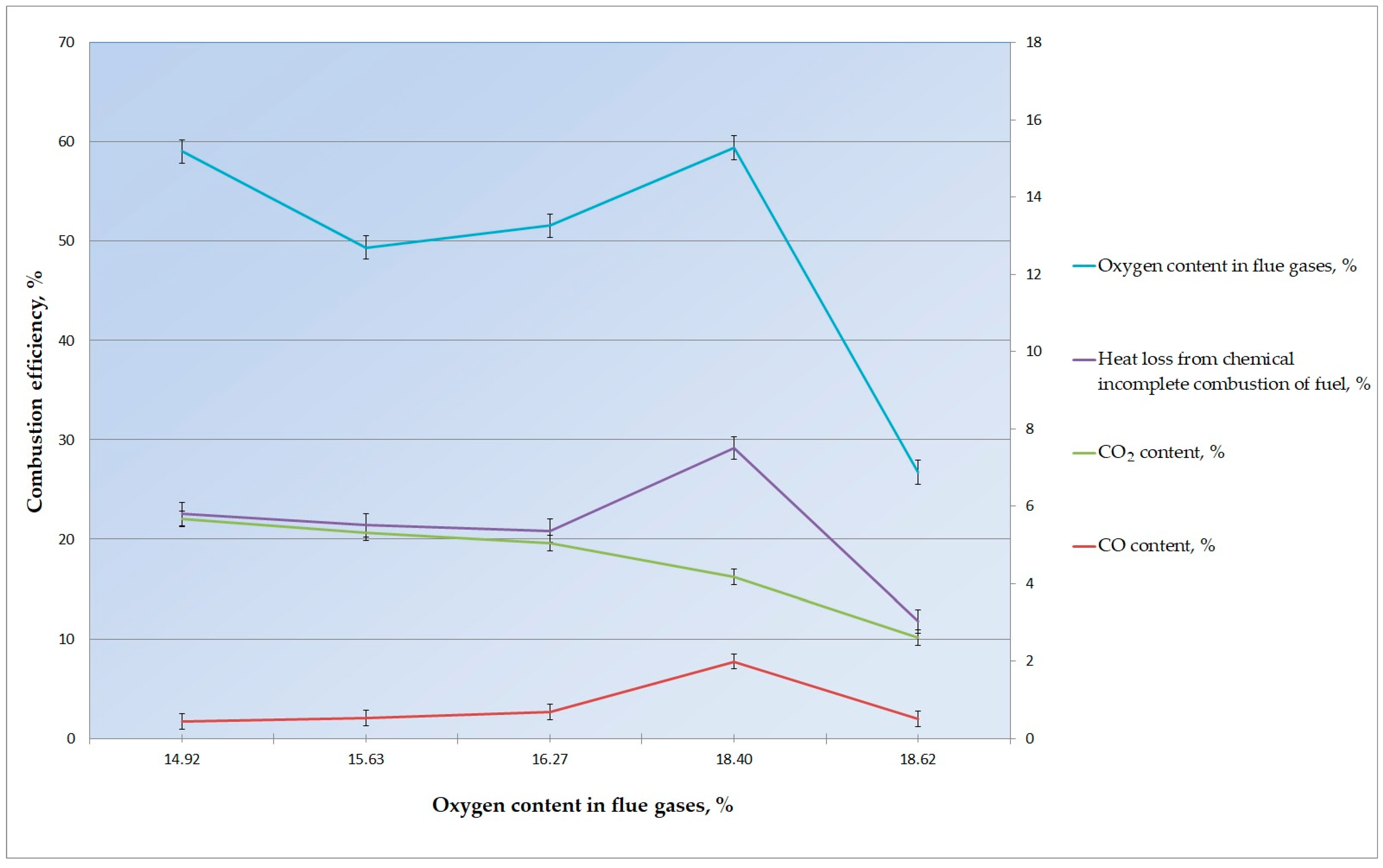
| O2, % | 18.40 | 15.630 | 14.920 | 16.270 | 17.620 | 1.251 |
| CO, % | 1.991 | 0.52 | 0.445 | 0.679 | 0.512 | 0.087 |
| SO2, % | 0.069 | 0.475 | 0.488 | 0.471 | 0.088 | 0.192 |
| NOx, % | 0.037 | 0.094 | 0.076 | 0.030 | 0.040 | 0.025 |
| CO2, % | 2.170 | 4.800 | 5.220 | 4.360 | 2.090 | 1.306 |
| H2, % | 0.366 | 0.074 | 0.047 | 0.069 | 0.105 | 0.116 |
| Temperature values (°C) | ||||||
| tflue gas | 156.7 | 374.0 | 344.7 | 318.4 | 242.8 | 76.9 |
| tambient air | 18.8 | 18.7 | 19.1 | 18.9 | 14.9 | 1.56 |
| Maximum content of CO and SO2 in dry combustion products at α = 1 | ||||||
| RO2max | 1.9979 | 0.5675 | 0.4938 | 0.7261 | 0.6000 | 0.066 |
| Calculation results | ||||||
| Value h | 0.4801 | 0.1067 | 0.0872 | 0.1441 | 0.2306 | 0.056 |
| Heat loss from chemical under-burning q3, % | 3.34 | 0.19 | 0.13 | 0.32 | 0.42 | 0.099 |
| Combustion efficiency, % | 59.43 | 49.38 | 59.03 | 51.56 | 49.32 | 5.10 |
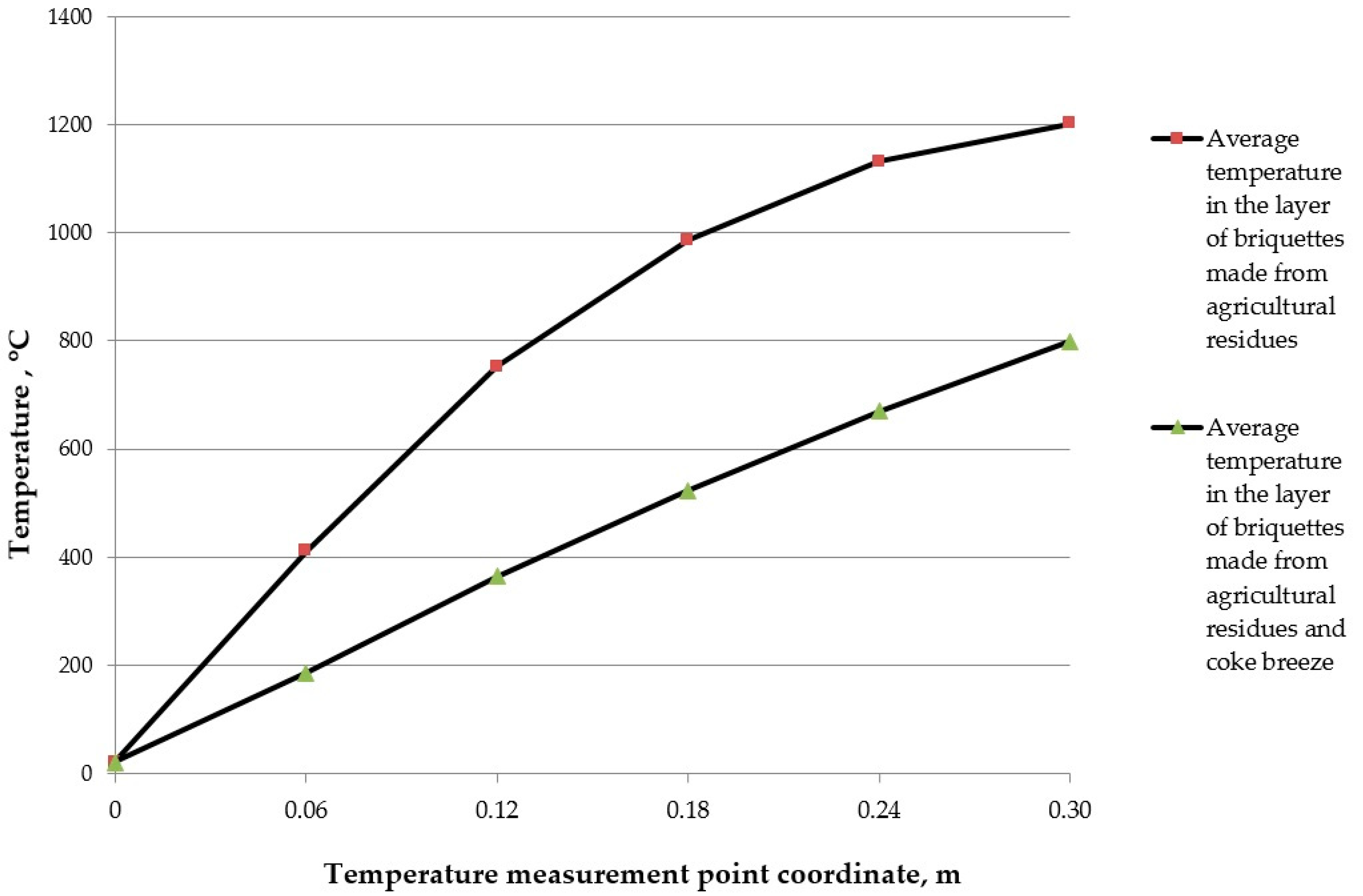
| a = 1.17·10−7 m2/s; τ = 900 s | |||||||||
|---|---|---|---|---|---|---|---|---|---|
| x, m | T(x, τ), °C | x, m | T(x, τ), °C | x, m | T(x, τ), °C | x, m | T(x, τ), °C | x, m | T(x, τ), °C |
| 0 | 20 | 0 | 20 | 0 | 20 | 0 | 20 | 0 | 20 |
| 0.02 | 118 | 0.03 | 213 | 0.04 | 280 | 0.05 | 347 | 0.06 | 411 |
| 0.04 | 280 | 0.06 | 411 | 0.08 | 475 | 0.10 | 648 | 0.12 | 752 |
| 0.06 | 411 | 0.09 | 593 | 0.12 | 752 | 0.15 | 881 | 0.18 | 987 |
| 0.08 | 475 | 0.12 | 752 | 0.16 | 918 | 0.20 | 1045 | 0.24 | 1132 |
| 0.10 | 648 | 0.15 | 881 | 0.20 | 1045 | 0.25 | 1145 | 0.30 | 1203 |
| a = 2.64·10−7 m2/s; τ = 2100 s | |||||||||
|---|---|---|---|---|---|---|---|---|---|
| x, m | T(x, τ), °C | x, m | T(x, τ), °C | x, m | T(x, τ), °C | x, m | T(x, τ), °C | x, m | T(x, τ), °C |
| 0 | 20 | 0 | 20 | 0 | 20 | 0 | 20 | 0 | 20 |
| 0.02 | 75 | 0.03 | 104 | 0.04 | 137 | 0.05 | 161 | 0.06 | 186 |
| 0.04 | 137 | 0.06 | 186 | 0.08 | 254 | 0.10 | 307 | 0.12 | 364 |
| 0.06 | 186 | 0.09 | 281 | 0.12 | 364 | 0.15 | 449 | 0.18 | 523 |
| 0.08 | 254 | 0.12 | 364 | 0.16 | 475 | 0.20 | 573 | 0.24 | 670 |
| 0.10 | 307 | 0.15 | 449 | 0.20 | 573 | 0.25 | 692 | 0.30 | 800 |
Disclaimer/Publisher’s Note: The statements, opinions and data contained in all publications are solely those of the individual author(s) and contributor(s) and not of MDPI and/or the editor(s). MDPI and/or the editor(s) disclaim responsibility for any injury to people or property resulting from any ideas, methods, instructions or products referred to in the content. |
© 2024 by the authors. Licensee MDPI, Basel, Switzerland. This article is an open access article distributed under the terms and conditions of the Creative Commons Attribution (CC BY) license (https://creativecommons.org/licenses/by/4.0/).
Share and Cite
Nikiforov, A.; Prikhodko, E.; Kinzhibekova, A.; Karmanov, A.; Alexiou Ivanova, T. Analysis of the Efficiency of Burning Briquettes from Agricultural and Industrial Residues in a Layer. Energies 2024, 17, 3070. https://doi.org/10.3390/en17133070
Nikiforov A, Prikhodko E, Kinzhibekova A, Karmanov A, Alexiou Ivanova T. Analysis of the Efficiency of Burning Briquettes from Agricultural and Industrial Residues in a Layer. Energies. 2024; 17(13):3070. https://doi.org/10.3390/en17133070
Chicago/Turabian StyleNikiforov, Alexandr, Evgeniy Prikhodko, Akmaral Kinzhibekova, Amangeldy Karmanov, and Tatiana Alexiou Ivanova. 2024. "Analysis of the Efficiency of Burning Briquettes from Agricultural and Industrial Residues in a Layer" Energies 17, no. 13: 3070. https://doi.org/10.3390/en17133070