

Reactor and Plant Designs for the Solar Photosynthesis of Fuels

 , , ,
, , ,  and
and 
Abstract
1. Introduction
- Use of co-catalyst: It is used to improve the electron–hole separation and to introduce possible visible light absorption through a plasmonic effect [15].
- Use of nanocarbon loading: Nanocarbon materials, such as carbon nanotubes, graphene or carbon dots, can serve as co-catalysts or electron acceptors on the surface of the photocatalyst. This can enhance the photocatalytic activity by promoting efficient charge separation and transfer, leading to improved conversion rates of CO2 into value-added products. They can also contribute to the photostability of the photocatalyst by mitigating photo corrosion or degradation phenomena, thereby extending the lifetime of the catalyst and improving its recyclability in CO2 photoreduction [16].
- Use of heterojunction construction: An efficient semiconductor should have a wide visible light response, long-term stability, efficient separation of electrons and holes and strong redox capacity in a photocatalytic reaction. Since it is challenging to have all the properties from a single material, a heterojunction uses two different semiconductors, which can be excited at a relatively short wavelength and improve charge separation by an appropriate migration of electrons and holes in the coupled materials [17].
- Use of surface sensitisation: Dyes can be used to absorb light with a broader range of wavelengths compared to the photocatalyst alone. By sensitising the photocatalyst with a dye, the overall light absorption efficiency of the system can be improved, thereby increasing the number of photons available for driving the CO2 photoreduction [18].
- Use of pore texture tailoring: It influences light scattering and absorption within the photocatalyst. By controlling the pore structure, it is possible to optimise light penetration and distribution throughout the catalyst, maximising photon absorption and utilisation. Also, pore structure modifications can influence the migration and transport of the photogenerated charge carriers within the photocatalyst. Well-designed pore structures can minimise electron–hole recombination and improve the efficiency of CO2 conversion. Additionally, tailoring the pore texture can influence the accessibility of different sites and pathways on the photocatalyst surface and this can lead to selective CO2 reduction, favouring the formation of specific target products such as carbon monoxide (CO) or methane (CH4) over undesired by-products [19].
- Use of dimensionality: It refers to manipulating the structural dimensions of the photocatalyst material, such as its thickness or morphology. The conversion of CO2 can be improved by changing these properties [20].
- Use of defect control: Defects on the photocatalyst surface can alter its chemical reactivity and interaction with CO2 molecules. By controlling defect types, it is possible to tailor the surface chemistry [20].
- Use of band-gap engineering: By engineering the band gap of the photocatalyst, it is possible to tailor its light absorption properties to better match the solar spectrum. This allows for a more efficient utilisation of sunlight, maximising photon absorption and providing the energy required for driving the CO2 photoreduction [21,22].
2. Fundamentals of Heterogeneous Photocatalysis and Mechanism
3. General Classification of Photoreactors
3.1. Slurry Photoreactors
- Liquid-suspended particles enable a high surface-area-to-volume ratio for the exposed photocatalyst.
- Inorganic salts have been reported to have a remarkable effect on the photoreduction of CO2. The addition of NaOH increases the solubility of CO2 with respect to pure H2O because OH− ions react with the CO2 to produce CO32− and HCO3−. It has been proposed that a high concentration of HCO3− in the system can accelerate the photoreduction reaction, improving its performance [38,72].
- Liquid-suspended particles remain inside the liquid stream and should be removed after the reaction. This creates substantial cost and complexity for separation and recycling.
- The progressive consumption of HS might cause the increment of the recombination rate of the electron–hole pairs. In continuous systems, the accumulation of spent HS is an issue.
3.1.1. Externally Side-Illuminated Slurry Photoreactors
3.1.2. Top-Illuminated Slurry Photoreactors
3.1.3. Internally Illuminated Slurry (IIS) Photoreactors
3.2. Fixed-Bed Photoreactors
3.2.1. Horizontal Photoreactors
3.2.2. Cylindrical Photoreactors
3.2.3. Thin-Film Photoreactors
3.2.4. Packed-Bed Photoreactors
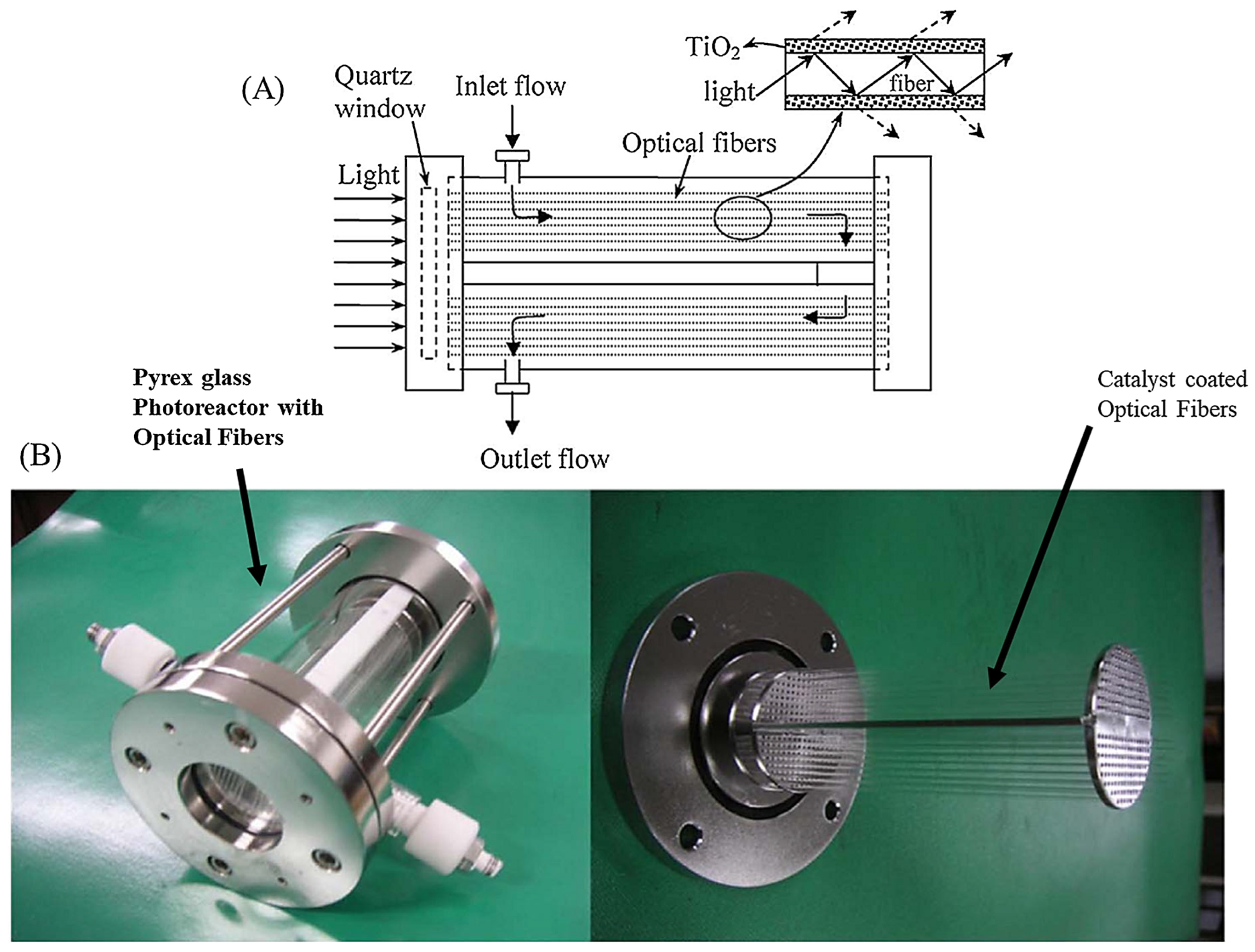
3.2.5. Optical Fibre Photoreactors
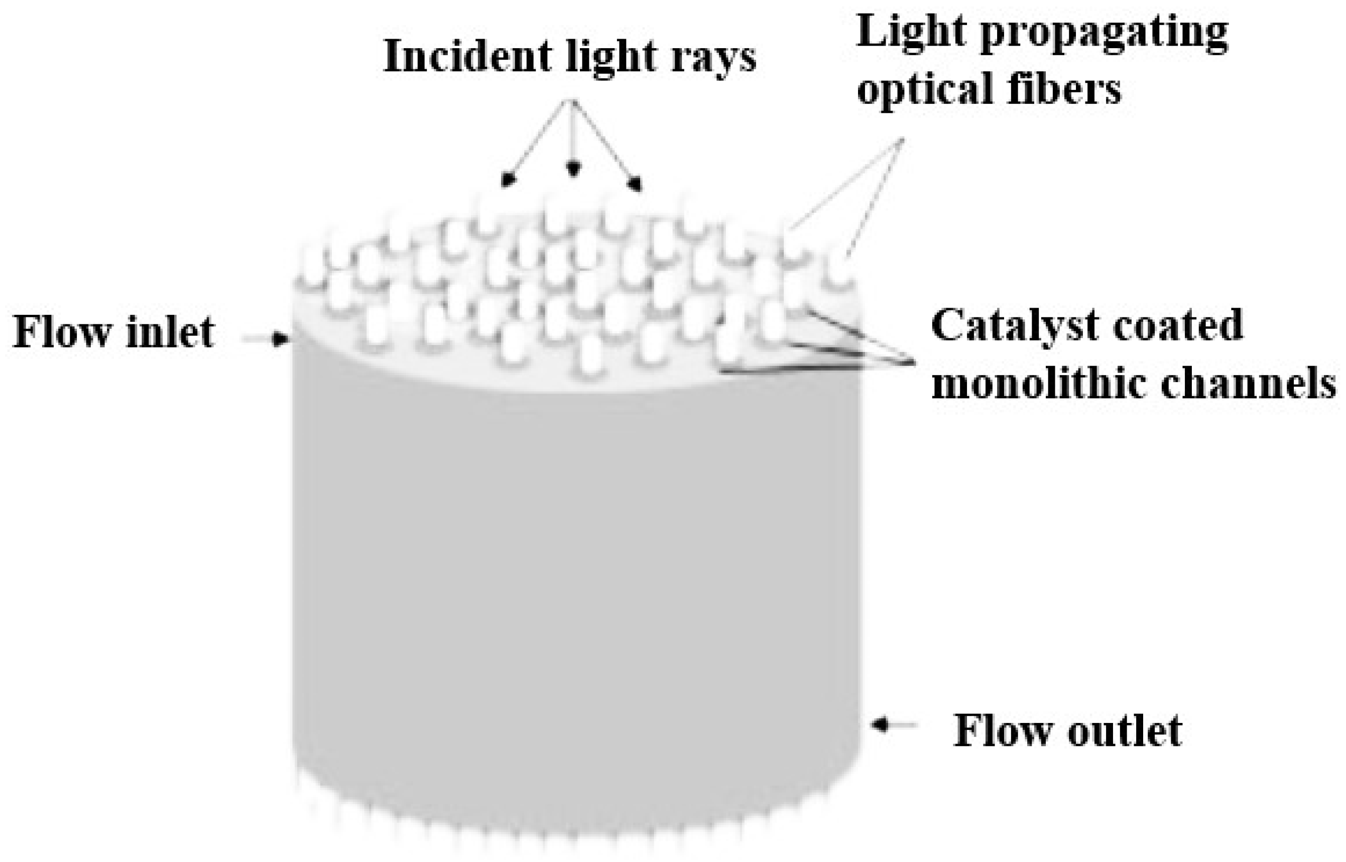
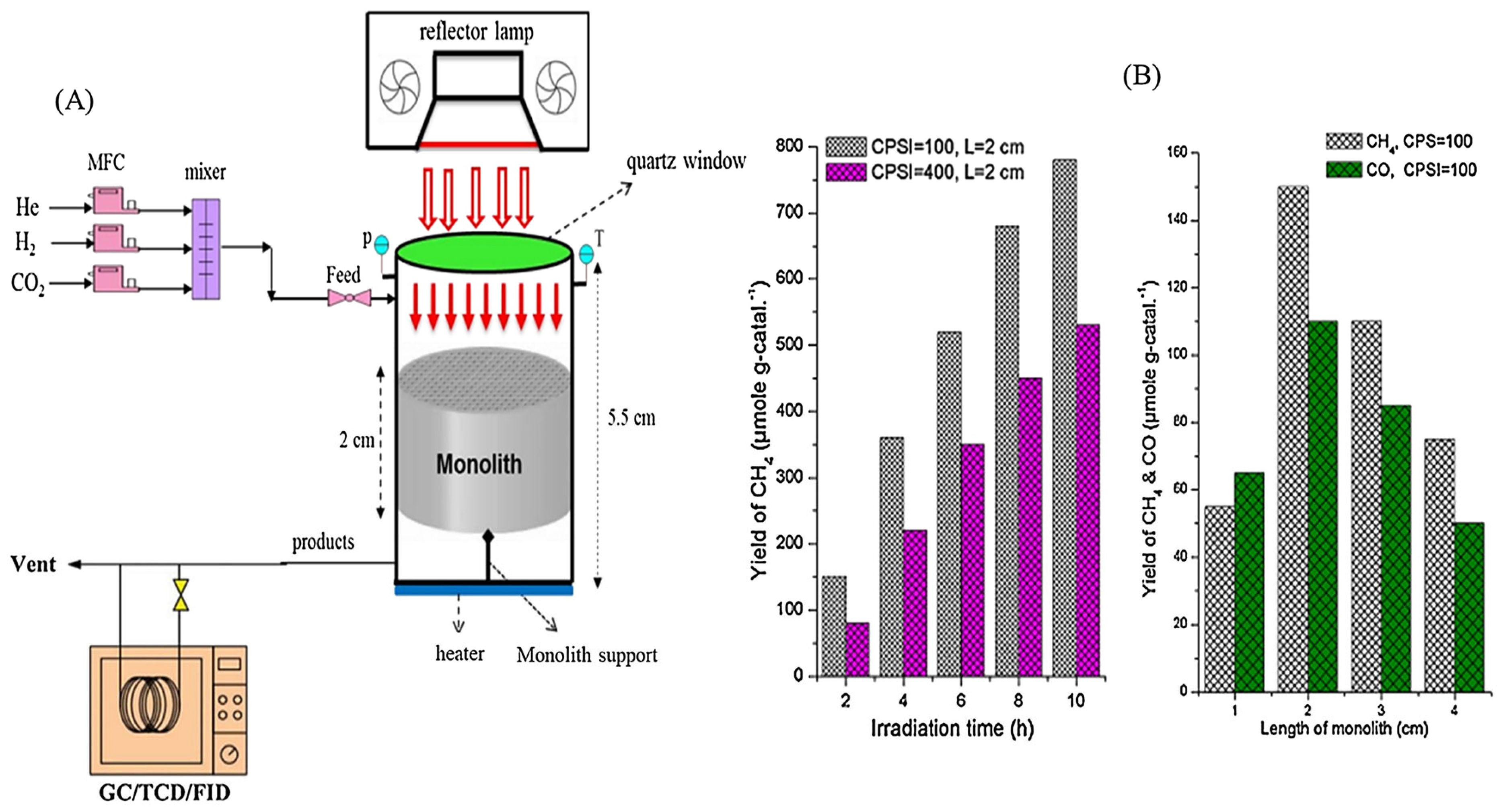
3.2.6. Monolith Photoreactors
3.2.7. Internally Illuminated Honeycomb Photoreactors
3.3. Membrane Photoreactors
3.3.1. Slurry-Type Membrane Photoreactors
3.3.2. Fixed-Bed Membrane Photoreactors
3.4. High-Pressure Photoreactors
3.5. Solar Photoreactors
3.5.1. The Effect of Parameters on the Performance of Solar Photoreactors
Solar Photoreactor Geometry and Configuration
Operating Conditions
3.6. Current Technologies for Concentrating Solar Systems
- Linear concentrating systems: The primary field of the mirrors has a linear pattern, and solar irradiation is concentrated within a narrow, linear region. The parabolic trough collector (PTC) and the linear Fresnel reflector (LFR) are the most representative solar concentrating technologies with linear configuration.
- Focal point concentrating systems: To maximise the concentration ratio and the operating temperature levels, the solar irradiation concentrates in a small area in comparison to the solar field. The primary reflectors generally have a circular pattern, and the solar towers (STs) and solar dishes (SDs) are the most representative technologies. Some common designs couple dishes with Stirling engines.
3.6.1. Basic Index Definitions for the Concentrating Solar Power Systems
3.6.2. Parabolic Trough Collector (PTC)
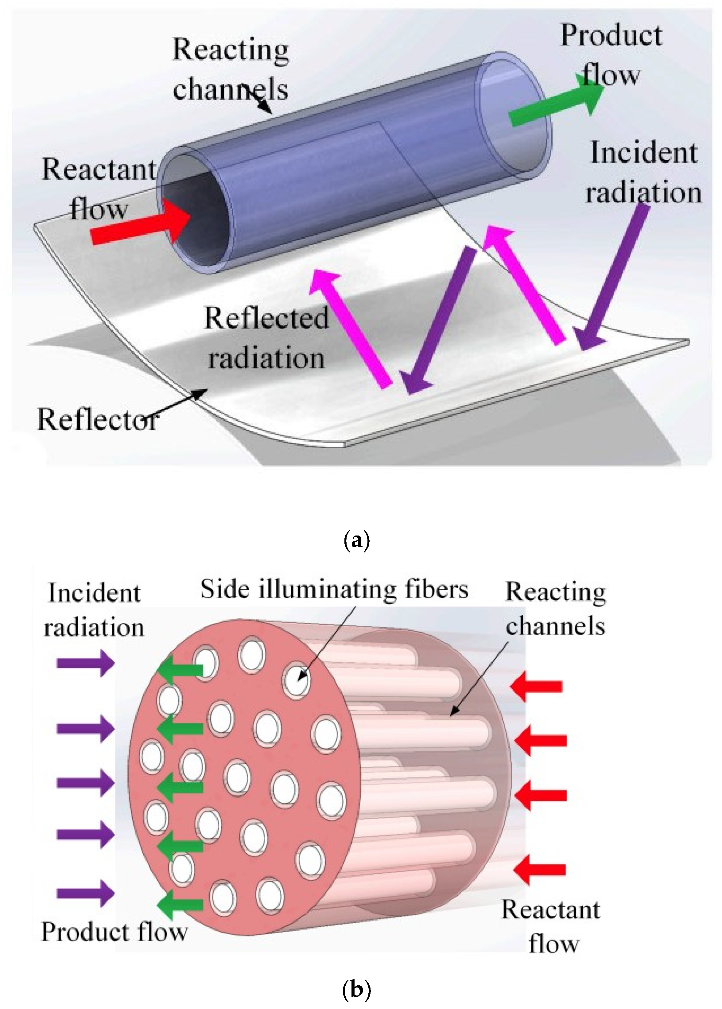
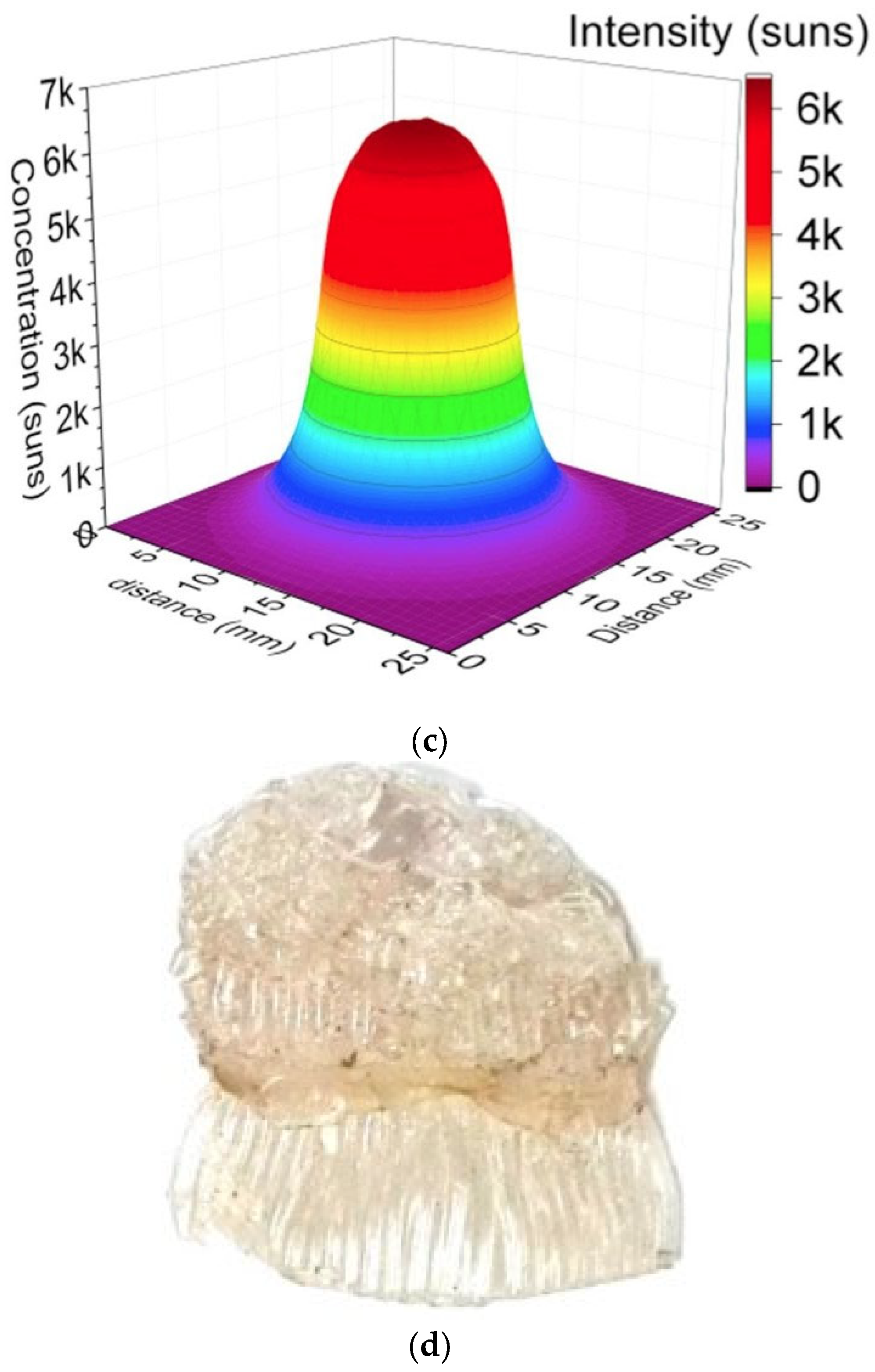
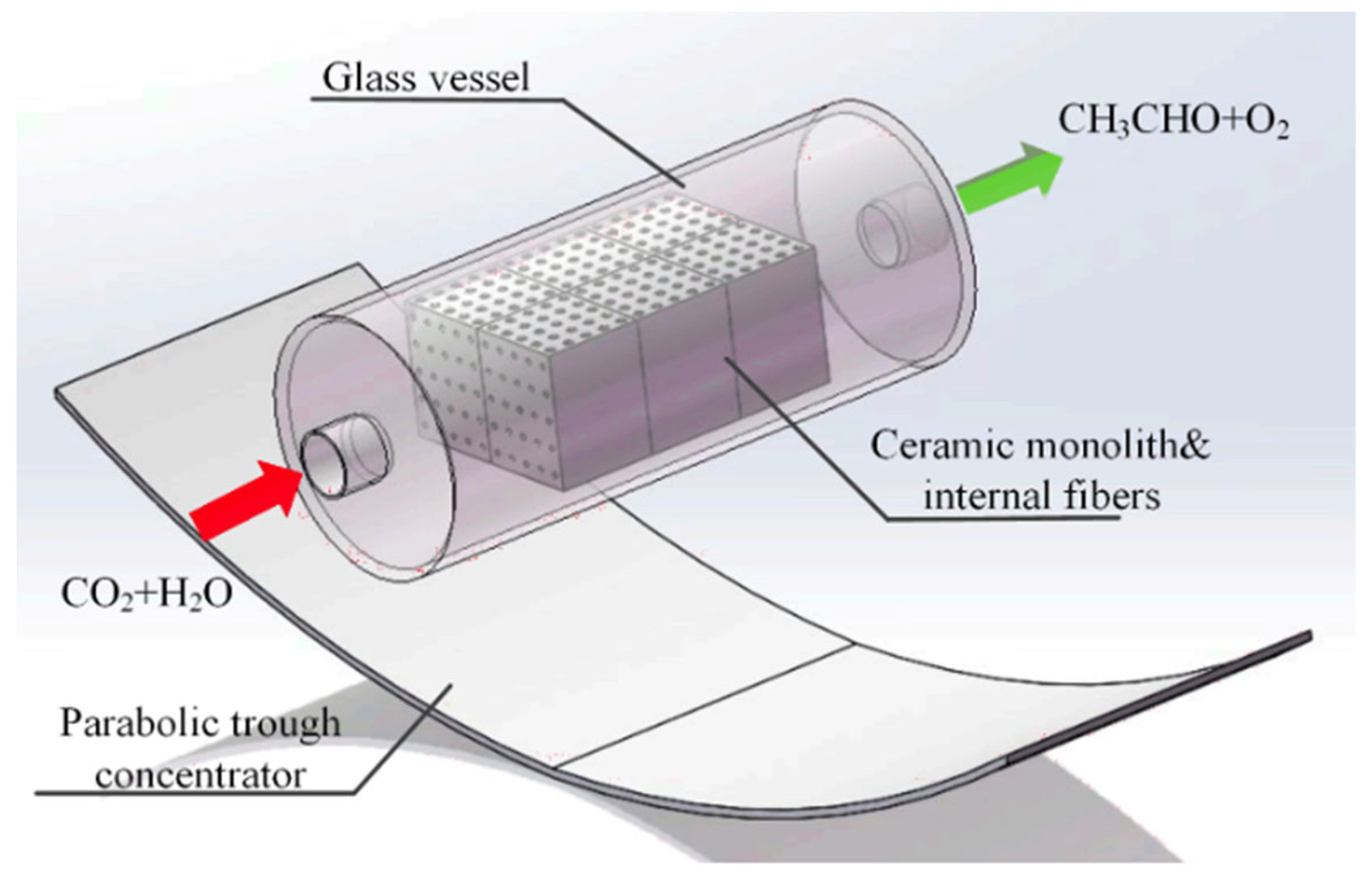
- In a standard continuous photoreactor incorporated with a trough concentrator, the flow of reactants is perpendicular to the incoming irradiation, as illustrated in Figure 25a. Conversely, in the OFMR, both the flow direction and incident rays align parallel to the reaction channels with the internal fibres, illustrated in Figure 25b. The introduction of a monolith into a transparent tube-like concentrated solar photoreactor vertically may cause an increased pressure drop along with the flow direction and the decrement in mass transfer efficiency. Because of these reasons, the requirement of concentrated irradiative flux distribution for OFMR is different. In an OFMR, the orientation of the optical fibres is uniform; by this way, incident rays become more appropriate for the configuration while the compound parabolic concentrators (CPCs) and surface uniform concentrators (SUCs) are structured to give a uniform irradiative flux distribution around the surface of the tubular vessels [157].
- The properties of the material for optical fibre restrict the use of the dish concentrators. The overheating of optical fibres with a dish concentrator creates a huge issue because of a high concentration ratio, as depicted in Figure 25, and the low melting point of the organic fibres in Figure 25d [158].
- Another challenging issue for a dish concentrator irradiated system is to enhance the reaction capacity due to the shadowing effect of the monolith. Therefore, the concentrated flux of a high concentrating ratio needs long reacting channels. However, this leads to an increase in installation costs in high altitude for large monoliths.
3.6.3. Linear Fresnel Reflector (LFR)
3.6.4. Solar Towers
3.6.5. Solar Dish
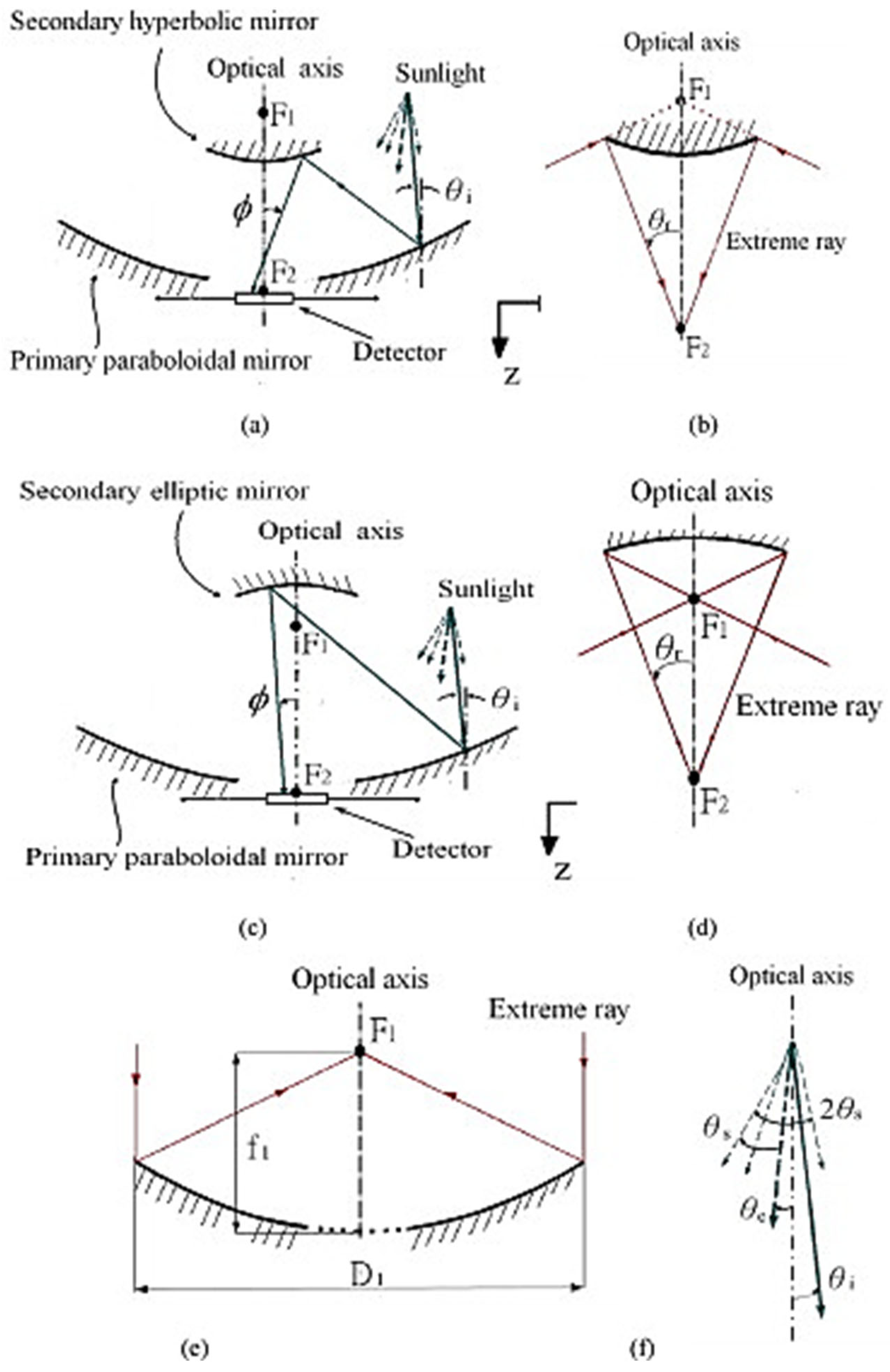
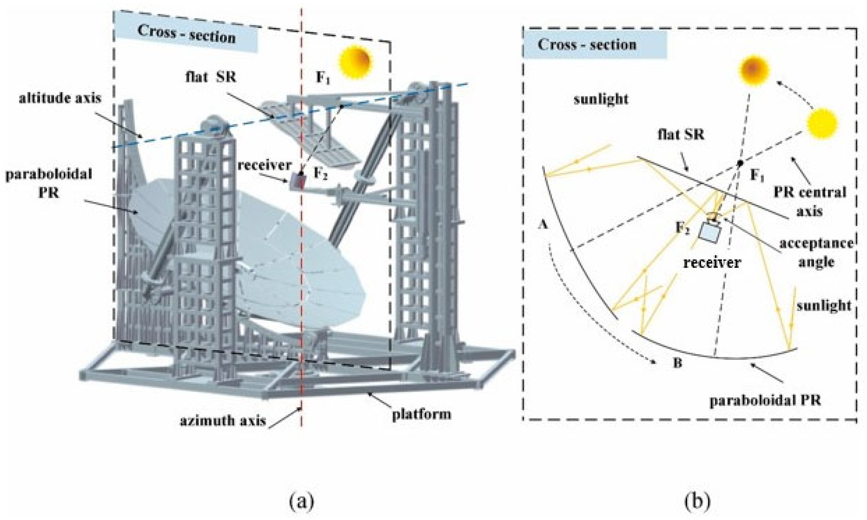
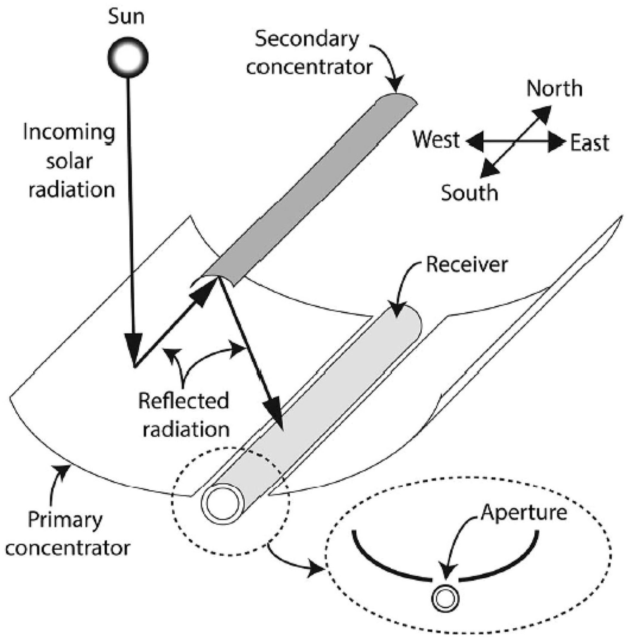
3.6.6. Solar Light Concentrator
- Parabolic concentrator.
- Hyperboloid concentrator.
- Fresnel lens concentrator.
- Compound parabolic concentrator (CPC).
- Dielectric totally internally reflecting concentrator (DTIRC).
- Flat high concentration devices.
- Quantum dot concentrator (QDC).
3.7. New Solar Concentrating Technologies
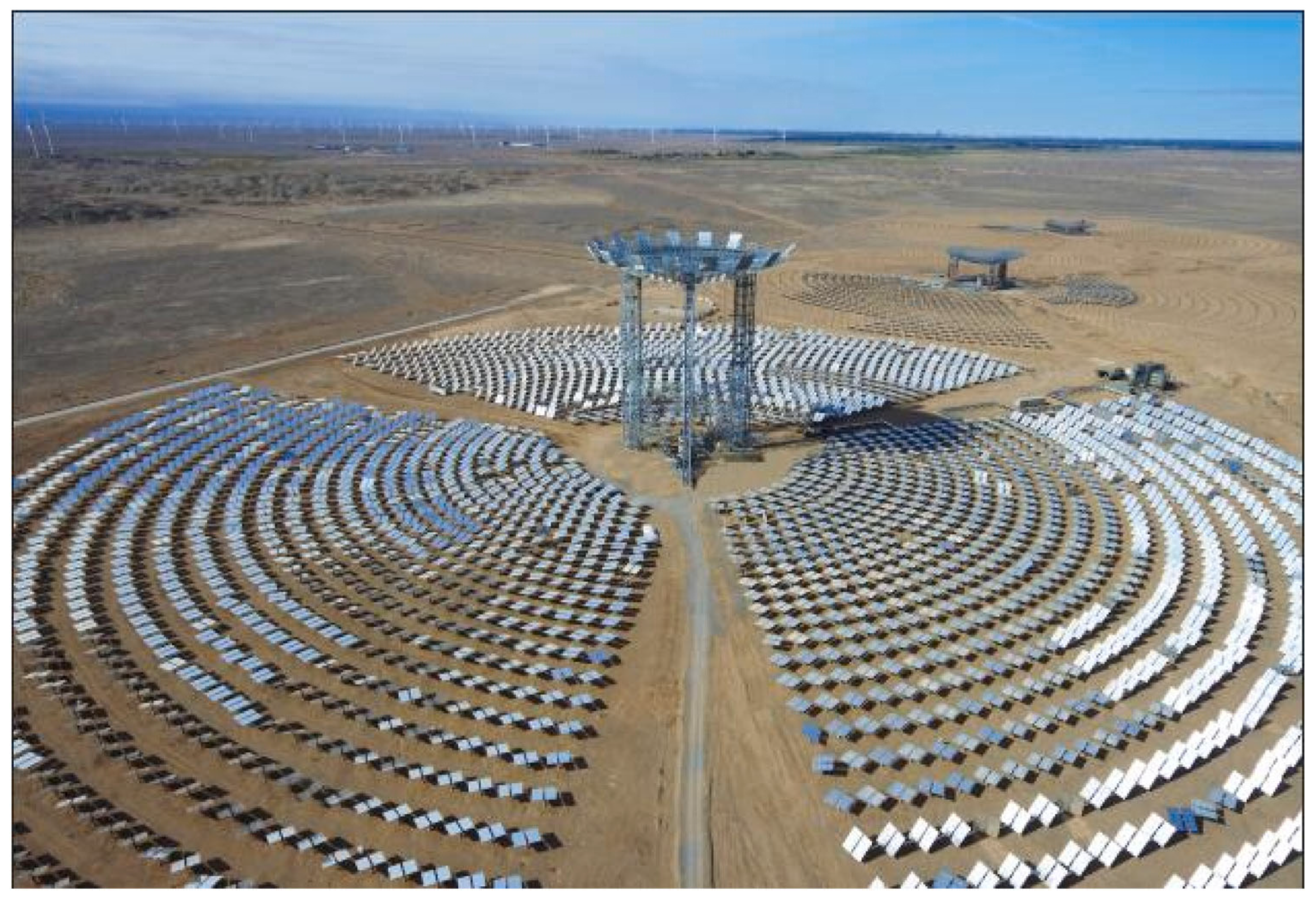
3.8. Beam-Down Concentrating Systems
4. Conclusions and Recommendations
4.1. Conclusions
4.2. Recommendations
Author Contributions
Funding
 I. Rossetti acknowledges Università degli Studi di Milano for support through the grant PSR 2021—GSA—Linea 6 “One Health Action Hub: University Task Force for the resilience of territorial ecosystems”. This study was carried out within the Agritech National Research Center and received funding from the European Union Next-Generation EU (PIANO NAZIONALE DI RIPRESA E RESILIENZA (PNRR)—MISSIONE 4 COMPONENTE 2, INVESTIMENTO 1.4—D.D. 1032 17/06/2022, CN00000022). This manuscript reflects only the authors’ views and opinions, neither the European Union nor the European Commission can be considered responsible for them. I. Rossetti and M. Tommasi acknowledge specifically the participation and funding of Tasks 8.2.3, 8.3.2 and 8.4.1.
Conflicts of Interest
References
- Soon, W.; Baliunas, S.L.; Robinson, A.B.; Robinson, Z.W. Environmental Effects of Increased Atmospheric Carbon Dioxide. Energy Environ. 1999, 10, 439–468. [Google Scholar] [CrossRef]
- Roy, S.C.; Varghese, O.K.; Paulose, M.; Grimes, C.A. Toward Solar Fuels: Photocatalytic Conversion of Carbon Dioxide to Hydrocarbons. ACS Nano 2010, 4, 1259–1278. [Google Scholar] [CrossRef] [PubMed]
- Liu, J.; Li, S.; Dewil, R.; Vanierschot, M.; Baeyens, J.; Deng, Y. Water Splitting by MnOx/Na2CO3 Reversible Redox Reactions. Sustainability 2022, 14, 7597. [Google Scholar] [CrossRef]
- Bafaqeer, A.; Tahir, M.; Amin, N.A.S. Well-designed ZnV2O6/g-C3N4 2D/2D nanosheets heterojunction with faster charges separation via pCN as mediator towards enhanced photocatalytic reduction of CO2 to fuels. Appl. Catal. B Environ. 2019, 242, 312–326. [Google Scholar] [CrossRef]
- Behroozi, A.H.; Xu, R. Photocatalytic CO2 reduction: Photocatalysts, membrane reactors, and hybrid processes. Chem. Catal. 2023, 3, 100550. [Google Scholar] [CrossRef]
- Ghoussoub, M.; Xia, M.; Duchesne, P.N.; Segal, D.; Ozin, G. Principles of photothermal gas-phase heterogeneous CO2 catalysis. Energy Environ. Sci. 2019, 12, 1122–1142. [Google Scholar] [CrossRef]
- Francis, A.; Kumar, H.; Sudhakar, K.; Tahir, M. A review on recent developments in solar photoreactors for carbon dioxide conversion to fuels. J. CO2 Util. 2021, 47, 101515. [Google Scholar] [CrossRef]
- Sakakura, T.; Choi, J.-C.; Yasuda, H. Transformation of Carbon Dioxide. Chem. Rev. 2007, 107, 2365–2387. [Google Scholar] [CrossRef] [PubMed]
- Shehzad, N.; Tahir, M.; Johari, K.; Murugesan, T.; Hussain, M. A critical review on TiO2 based photocatalytic CO2 reduction system: Strategies to improve efficiency. J. CO2 Util. 2018, 26, 98–122. [Google Scholar] [CrossRef]
- Khan, A.A.; Tahir, M. Recent advancements in engineering approach towards design of photo-reactors for selective photocatalytic CO2 reduction to renewable fuels. J. CO2 Util. 2019, 29, 205–239. [Google Scholar] [CrossRef]
- Tahir, M.; Amin, N.S. Advances in visible light responsive titanium oxide-based photocatalysts for CO2 conversion to hydrocarbon fuels. Energy Convers. Manag. 2013, 76, 194–214. [Google Scholar] [CrossRef]
- Abdullah, H.; Khan, M.M.R.; Ong, H.R.; Yaakob, Z. Modified TiO2 photocatalyst for CO2 photocatalytic reduction: An overview. J. CO2 Util. 2017, 22, 15–32. [Google Scholar] [CrossRef]
- Linsebigler, A.L.; Lu, G.; Yates, J.T. Photocatalysis on TiO2 Surfaces: Principles, Mechanisms, and Selected Results. Chem. Rev. 1995, 95, 735–758. [Google Scholar] [CrossRef]
- Ola, O.; Maroto-Valer, M.M. Review of material design and reactor engineering on TiO2 photocatalysis for CO2 reduction. J. Photochem. Photobiol. C Photochem. Rev. 2015, 24, 16–42. [Google Scholar] [CrossRef]
- Wang, Y.; Bai, X.; Qin, H.; Wang, F.; Li, Y.; Li, X.; Kang, S.; Zuo, Y.; Cui, L. Facile One-Step Synthesis of Hybrid Graphitic Carbon Nitride and Carbon Composites as High-Performance Catalysts for CO2 Photocatalytic Conversion. ACS Appl. Mater. Interfaces 2016, 8, 17212–17219. [Google Scholar] [CrossRef] [PubMed]
- Xu, Y.; Xu, H.; Wang, L.; Yan, J.; Li, H.; Song, Y.; Huang, L.; Cai, G. The CNT modified white C3N4 composite photocatalyst with enhanced visible-light response photoactivity. J. Chem. Soc. Dalt. Trans. 2013, 42, 7604–7613. [Google Scholar] [CrossRef]
- Cheng, H.; Hou, J.; Takeda, O.; Guo, X.-M.M.; Zhu, H. A unique Z-scheme 2D/2D nanosheet heterojunction design to harness charge transfer for photocatalysis. J. Mater. Chem. A 2015, 3, 11006–11013. [Google Scholar] [CrossRef]
- Li, Z.; Zhou, Y.; Zhang, J.; Tu, W.; Liu, Q.; Yu, T.; Zou, Z. Hexagonal Nanoplate-Textured Micro-Octahedron Zn2 SnO4: Combined Effects toward Enhanced Efficiencies of Dye-Sensitized Solar Cell and Photoreduction of CO2 into Hydrocarbon Fuels. Cryst. Growth Des. 2012, 12, 1476–1481. [Google Scholar] [CrossRef]
- Sun, J.; Zhang, J.; Zhang, M.; Antonietti, M.; Fu, X.; Wang, X. Bioinspired hollow semiconductor nanospheres as photosynthetic nanoparticles. Nat. Commun. 2012, 3, 1139. [Google Scholar] [CrossRef]
- Niu, P.; Yang, Y.; Yu, J.C.; Liu, G.; Cheng, H.-M. Switching the selectivity of the photoreduction reaction of carbon dioxide by controlling the band structure of a g-C 3N4 photocatalyst. Chem. Commun. 2014, 50, 10837. [Google Scholar] [CrossRef] [PubMed]
- Cao, S.; Low, J.; Yu, J.; Jaroniec, M.; Materials, M.J.-A. Undefined 2015 Polymeric photocatalysts based on graphitic carbon nitride. Adv. Mater. 2015, 27, 2150–2176. [Google Scholar] [CrossRef] [PubMed]
- Zheng, Y.; Lin, L.; Wang, B.; Wang, X. Graphitic Carbon Nitride Polymers toward Sustainable Photoredox Catalysis. Angew. Chem. Int. Ed. 2015, 54, 12868–12884. [Google Scholar] [CrossRef] [PubMed]
- Nguyen, T.-V.; Wu, J.C.S.; Chiou, C.-H. Photoreduction of CO2 over Ruthenium dye-sensitized TiO2-based catalysts under concentrated natural sunlight. Catal. Commun. 2008, 9, 2073–2076. [Google Scholar] [CrossRef]
- Renz, C. Lichtreaktionen der Oxyde des Titans, Cers und der Erdsäuren. Helv. Chim. Acta 1921, 4, 961–968. [Google Scholar] [CrossRef]
- Salgado, B.C.B.; Cardeal, R.A.; Valentini, A. Photocatalysis and Photodegradation of Pollutants. In Nanomaterials Applications for Environmental Matrices; do Nascimento, R.F., Ferreira, O.P., De Paula, A.J., de Oliveira Sousa Neto, V., Eds.; Advanced Nanomaterials; Elsevier: Amsterdam, The Netherlands, 2019; pp. 449–488. ISBN 978-0-12-814829-7. [Google Scholar] [CrossRef]
- Verbruggen, S.W. TiO2 photocatalysis for the degradation of pollutants in gas phase: From morphological design to plasmonic enhancement. J. Photochem. Photobiol. C Photochem. Rev. 2015, 24, 64–82. [Google Scholar] [CrossRef]
- de Brito Lira, J.O.; Riella, H.G.; Padoin, N.; Soares, C. An Overview of Photoreactors and Computational Modeling for the Intensification of Photocatalytic Processes in the Gas-Phase: State-of-Art. J. Environ. Chem. Eng. 2021, 9, 105068. [Google Scholar] [CrossRef]
- Yu, M.; Wang, J.; Tang, L.; Feng, C.; Liu, H.; Zhang, H.; Peng, B.; Chen, Z.; Xie, Q. Intimate coupling of photocatalysis and biodegradation for wastewater treatment: Mechanisms, recent advances and environmental applications. Water Res. 2020, 175, 115673. [Google Scholar] [CrossRef] [PubMed]
- Wood, D.; Shaw, S.; Cawte, T.; Shanen, E.; Heyst, B. Van An overview of photocatalyst immobilization methods for air pollution remediation. Chem. Eng. J. 2020, 391, 123490. [Google Scholar] [CrossRef]
- Nakata, K.; Fujishima, A. TiO2 photocatalysis: Design and applications. J. Photochem. Photobiol. C Photochem. Rev. 2012, 13, 169–189. [Google Scholar] [CrossRef]
- Ângelo, J.; Andrade, L.; Madeira, L.M.; Mendes, A. An overview of photocatalysis phenomena applied to NOx abatement. J. Environ. Manag. 2013, 129, 522–539. [Google Scholar] [CrossRef] [PubMed]
- An, J.R.; Wang, Y.; Dong, W.W.; Gao, X.J.; Yang, O.Y.; Liu, Y.L.; Zhao, J.; Li, D.S. Efficient Visible-Light Photoreduction of CO2 to CH4 over an Fe-Based Metal-Organic Framework (PCN-250-Fe3) in a Solid-Gas Mode. ACS Appl. Energy Mater. 2022, 5, 2384–2390. [Google Scholar] [CrossRef]
- Yang, O.Y.; Gao, X.J.; Qi, G.D.; Wang, Y.; Dong, W.W.; Tian, Z.F.; Zhao, J.; Li, D.S.; Zhang, Q. Dye-Anchoring Strategy with a Metal-Organic Framework for a Highly Efficient Visible-Light-Driven Photocatalytic CO2 Reduction through the Solid-Gas Mode. ACS Appl. Energy Mater. 2023, 6, 334–341. [Google Scholar] [CrossRef]
- Dong, W.W.; Jia, J.; Wang, Y.; An, J.R.; Yang, O.Y.; Gao, X.J.; Liu, Y.L.; Zhao, J.; Li, D.S. Visible-light-driven solvent-free photocatalytic CO2 reduction to CO by Co-MOF/Cu2O heterojunction with superior selectivity. Chem. Eng. J. 2022, 438, 135622. [Google Scholar] [CrossRef]
- Han, H.; Han, T.; Luo, Y.; Mushtaq, M.A.; Jia, Y.; Liu, C. Recent advances in α-Fe2O3-based photocatalysts for CO2 conversion to solar fuels. J. Ind. Eng. Chem. 2023, 128, 81–94. [Google Scholar] [CrossRef]
- Pan, Q.; Wu, Y.; Su, X.; Yin, Y.; Shi, S.; Oderinde, O.; Yui, G.; Zhang, C.; Zhang, Y. A review on the recent development of bismuth-based catalysts for CO2 photoreduction. J. Mol. Struct. 2023, 1294, 136404. [Google Scholar] [CrossRef]
- Anus, A.; Park, S. The synthesis and key features of 3D carbon nitrides (C3N4) used for CO2 photoreduction. Chem. Eng. J. 2024, 486, 150213. [Google Scholar] [CrossRef]
- Conte, F.; Villa, A.; Prati, L.; Pirola, C.; Bennici, S.; Ramis, G.; Rossetti, I. Effect of Metal Cocatalysts and Operating Conditions on the Product Distribution and the Productivity of the CO2 Photoreduction. Ind. Eng. Chem. Res. 2022, 61, 2963–2972. [Google Scholar] [CrossRef] [PubMed]
- Rossetti, I.; Bahadori, E.; Tripodi, A.; Villa, A.; Prati, L.; Ramis, G. Conceptual design and feasibility assessment of photoreactors for solar energy storage. Sol. Energy 2018, 172, 225–231. [Google Scholar] [CrossRef]
- Conte, F.; Tripodi, A.; Rossetti, I.; Ramis, G. Feasibility Study of the Solar-Promoted Photoreduction of CO2 to Liquid Fuels with Direct or Indirect Use of Renewable Energy Sources. Energies 2021, 14, 2804. [Google Scholar] [CrossRef]
- Yue, P.L. Introduction to the Modelling and Design of Photoreactors. In Photoelectrochemistry, Photocatalysis and Photoreactors; Springer: Amsterdam, The Netherlands, 1985; pp. 527–547. [Google Scholar]
- Nguyen, V.-H.; Wu, J.C.S. Recent developments in the design of photoreactors for solar energy conversion from water splitting and CO2 reduction. Appl. Catal. A Gen. 2018, 550, 122–141. [Google Scholar] [CrossRef]
- Rossetti, I.; Bahadori, E.; Tripodi, A.; Ramis, G. Modelling of photoreactors for water treatment. Chem. Eng. Trans. 2019, 74, 289–294. [Google Scholar] [CrossRef]
- Ibhadon, A.O.; Fitzpatrick, P. Heterogeneous photocatalysis: Recent advances and applications. Catalysts 2013, 3, 189–218. [Google Scholar] [CrossRef]
- Sayama, K.; Arakawa, H. Photocatalytic decomposition of water and photocatalytic reduction of carbon dioxide over zirconia catalyst. J. Phys. Chem. 1993, 97, 531–533. [Google Scholar] [CrossRef]
- Zhang, Z.; Huang, Z.; Cheng, X.; Wang, Q.; Chen, Y.; Dong, P.; Zhang, X. Product selectivity of visible-light photocatalytic reduction of carbon dioxide using titanium dioxide doped by different nitrogen-sources. Appl. Surf. Sci. 2015, 355, 45–51. [Google Scholar] [CrossRef]
- Sato, S.; Arai, T.; Morikawa, T.; Uemura, K.; Suzuki, T.M.; Tanaka, H.; Kajino, T. Selective CO2 Conversion to Formate Conjugated with H2O Oxidation Utilizing Semiconductor/Complex Hybrid Photocatalysts. J. Am. Chem. Soc. 2011, 133, 15240–15243. [Google Scholar] [CrossRef] [PubMed]
- Asi, M.A.; He, C.; Su, M.; Xia, D.; Lin, L.; Deng, H.; Xiong, Y.; Qiu, R.; Li, X. Photocatalytic reduction of CO2 to hydrocarbons using AgBr/TiO2 nanocomposites under visible light. Catal. Today 2011, 175, 256–263. [Google Scholar] [CrossRef]
- Wang, J.-C.J.-S.; Yao, H.-C.; Fan, Z.-Y.; Zhang, L.; Wang, J.-C.J.-S.; Zang, S.-Q.; Li, Z.-J. Indirect Z-Scheme BiOI/g-C3N4 Photocatalysts with Enhanced Photoreduction CO2 Activity under Visible Light Irradiation. ACS Appl. Mater. Interfaces 2016, 8, 3765–3775. [Google Scholar] [CrossRef] [PubMed]
- Ye, Z. Handbook of Advanced Dielectric, Piezoelectric and Ferroelectric Materials: Synthesis, Properties and Applications; Ye, Z.-G., Ed.; Woodhead Publishing: Sawston, UK, 2008; ISBN 978-1-84569-186-8. [Google Scholar]
- Spadoni, G.; Bandini, E.; Santarelli, F. Scattering effects in photosensitized reactions. Chem. Eng. Sci. 1978, 33, 517–524. [Google Scholar] [CrossRef]
- Cassano, A.E.; Alfano, O.M. Design and Analysis of Homogeneous and Heterogeneous Photoreactors. In Chemical Engineering; Wiley: Hoboken, NJ, USA, 2005; pp. 125–169. [Google Scholar]
- Liu, L.; Li, Y.; He, J.; Wang, Q.; Deng, J.; Chen, X.; Yu, C. Progress on gas-solid phase photoreactor and its application in CO2 reduction. Green Chem. Eng. 2023; in press. [Google Scholar] [CrossRef]
- Tahir, M.; Amin, N.A.S. Indium-doped TiO2 nanoparticles for photocatalytic CO2 reduction with H2O vapors to CH4. Appl. Catal. B Environ. 2015, 162, 98–109. [Google Scholar] [CrossRef]
- Li, X.; Bi, W.; Wang, Z.; Zhu, W.; Chu, W.; Wu, C.; Xie, Y. Surface-adsorbed ions on TiO2 nanosheets for selective photocatalytic CO2 reduction. Nano Res. 2018, 11, 3362–3370. [Google Scholar] [CrossRef]
- Xin, C.; Hu, M.; Wang, K.; Wang, X. Significant Enhancement of Photocatalytic Reduction of CO2 with H2O over ZnO by the Formation of Basic Zinc Carbonate. Langmuir 2017, 33, 6667–6676. [Google Scholar] [CrossRef] [PubMed]
- Tasbihi, M.; Kočí, K.; Edelmannová, M.; Troppová, I.; Reli, M.; Schomäcker, R. Pt/TiO2 photocatalysts deposited on commercial support for photocatalytic reduction of CO2. J. Photochem. Photobiol. A Chem. 2018, 366, 72–80. [Google Scholar] [CrossRef]
- Lee, D.K.; Choi, J.I.; Lee, G.H.; Kim, Y.H.; Kang, J.K. Energy States of a Core-Shell Metal Oxide Photocatalyst Enabling Visible Light Absorption and Utilization in Solar-to-Fuel Conversion of Carbon Dioxide. Adv. Energy Mater. 2016, 6, 1–7. [Google Scholar] [CrossRef]
- Razzaq, A.; Grimes, C.A.; In, S. Il Facile fabrication of a noble metal-free photocatalyst: TiO2 nanotube arrays covered with reduced graphene oxide. Carbon 2016, 98, 537–544. [Google Scholar] [CrossRef]
- Kim, K.H.; Kim, S.; Moon, B.C.; Choi, J.W.; Jeong, H.M.; Kwon, Y.; Kwon, S.; Choi, H.S.; Kang, J.K. Quadruple metal-based layered structure as the photocatalyst for conversion of carbon dioxide into a value added carbon monoxide with high selectivity and efficiency. J. Mater. Chem. A 2017, 5, 8274–8279. [Google Scholar] [CrossRef]
- Kandy, M.M.; Gaikar, V.G. Enhanced photocatalytic reduction of CO2 using CdS/Mn2O3 nanocomposite photocatalysts on porous anodic alumina support with solar concentrators. Renew. Energy 2019, 139, 915–923. [Google Scholar] [CrossRef]
- Li, X.; Sun, Y.; Xu, J.; Shao, Y.; Wu, J.; Xu, X.; Pan, Y.; Ju, H.; Zhu, J.; Xie, Y. Selective visible-light-driven photocatalytic CO2 reduction to CH4 mediated by atomically thin CuIn5S8 layers. Nat. Energy 2019, 4, 690–699. [Google Scholar] [CrossRef]
- Nguyen, T.-V.; Wu, J.C.S. Photoreduction of CO2 in an optical-fiber photoreactor: Effects of metals addition and catalyst carrier. Appl. Catal. A Gen. 2008, 335, 112–120. [Google Scholar] [CrossRef]
- Nguyen, T.-V.; Wu, J.C.S. Photoreduction of CO2 to fuels under sunlight using optical-fiber reactor. Sol. Energy Mater. Sol. Cells 2008, 92, 864–872. [Google Scholar] [CrossRef]
- Wu, J.C.S.; Lin, H.-M.; Lai, C.-L. Photo reduction of CO2 to methanol using optical-fiber photoreactor. Appl. Catal. A Gen. 2005, 296, 194–200. [Google Scholar] [CrossRef]
- Tahir, M. Photocatalytic carbon dioxide reduction to fuels in continuous flow monolith photoreactor using montmorillonite dispersed Fe/TiO2 nanocatalyst. J. Clean. Prod. 2018, 170, 242–250. [Google Scholar] [CrossRef]
- Tahir, M.; Amin, N.S. Photocatalytic CO2 reduction with H2O vapors using montmorillonite/TiO2 supported microchannel monolith photoreactor. Chem. Eng. J. 2013, 230, 314–327. [Google Scholar] [CrossRef]
- Tong, K.; Chen, L.; Yang, L.; Du, X.; Yang, Y. Energy transport of photocatalytic carbon dioxide reduction in optical fiber honeycomb reactor coupled with trough concentrated solar power. Catalysts 2021, 11, 829. [Google Scholar] [CrossRef]
- Cheng, M.; Yang, S.; Chen, R.; Zhu, X.; Liao, Q.; Huang, Y. Copper-decorated TiO2 nanorod thin films in optofluidic planar reactors for efficient photocatalytic reduction of CO2. Int. J. Hydrogen Energy 2017, 42, 9722–9732. [Google Scholar] [CrossRef]
- Cheng, M.; Yang, S.; Chen, R.; Zhu, X.; Liao, Q.; Huang, Y. Visible light responsive CdS sensitized TiO2 nanorod array films for efficient photocatalytic reduction of gas phase CO2. Mol. Catal. 2018, 448, 185–194. [Google Scholar] [CrossRef]
- Fernández-Catalá, J.; Navlani-García, M.; Berenguer-Murcia, Á.; Cazorla-Amorós, D. Exploring CuxO-doped TiO2 modified with carbon nanotubes for CO2 photoreduction in a 2D-flow reactor. J. CO2 Util. 2021, 54, 101796. [Google Scholar] [CrossRef]
- Tseng, I.-H.; Chang, W.-C.; Wu, J.C.S. Photoreduction of CO2 using sol–gel derived titania and titania-supported copper catalysts. Appl. Catal. B Environ. 2002, 37, 37–48. [Google Scholar] [CrossRef]
- Chen, D.; Sivakumar, M.; Ray, A.K. Heterogeneous Photocatalysis in Environmental Remediation. Dev. Chem. Eng. Miner. Process. 2000, 8, 505–550. [Google Scholar] [CrossRef]
- Ray, A.K.; Beenackers, A.A.C.M. Development of a new photocatalytic reactor for water purification. Catal. Today 1998, 40, 73–83. [Google Scholar] [CrossRef]
- Pozzo, R.L.; Giombi, J.L.; Baltanás, M.A.; Cassano, A.E. Performance in a fluidized bed reactor of photocatalysts immobilized onto inert supports. Catal. Today 2000, 62, 175–187. [Google Scholar] [CrossRef]
- Kočí, K.; Obalová, L.; Matějová, L.; Plachá, D.; Lacný, Z.; Jirkovský, J.; Šolcová, O. Effect of TiO2 particle size on the photocatalytic reduction of CO2. Appl. Catal. B Environ. 2009, 89, 494–502. [Google Scholar] [CrossRef]
- Braham, R.J.; Harris, A.T. A complete multi-scale simulation of light absorption within a fluidized bed photoreactor using integrated particle, fluid and photon behaviour models. Phys. Chem. Chem. Phys. 2013, 15, 12373. [Google Scholar] [CrossRef] [PubMed]
- Ola, O.; Maroto-Valer, M.; Liu, D.; Mackintosh, S.; Lee, C.-W.; Wu, J.C.S. performance comparison of CO2 conversion in slurry and monolith photoreactors using Pd and Rh-TiO2 catalyst under ultraviolet irradiation. Appl. Catal. B Environ. 2012, 126, 172–179. [Google Scholar] [CrossRef]
- Sastre, F.; Corma, A.; García, H. 185 nm Photoreduction of CO2 to Methane by Water. Influence of the Presence of a Basic Catalyst. J. Am. Chem. Soc. 2012, 134, 14137–14141. [Google Scholar] [CrossRef] [PubMed]
- Bafaqeer, A.; Tahir, M.; Amin, N.A.S.; Al-Bastaki, N.; Altowayti, W.A.H.; Thabit, H.A. Performance analysis of externally reflected photoreactor for CO2 conversion to methanol using f-C3N4/ZnV2O6 S-scheme photocatalyst. Environ. Technol. Innov. 2023, 30, 103032. [Google Scholar] [CrossRef]
- Yurdakal, S.; Loddo, V.; Ferrer, B.B.; Palmisano, G.; Augugliaro, V.; Farreras, J.G.; Palmisano, L. Optical Properties of TiO2 Suspensions: Influence of pH and Powder Concentration on Mean Particle Size. Ind. Eng. Chem. Res. 2007, 46, 7620–7626. [Google Scholar] [CrossRef]
- Ambrožová, N.; Reli, M.; Šihor, M.; Kuśtrowski, P.; Wu, J.C.S.; Kočí, K. Copper and platinum doped titania for photocatalytic reduction of carbon dioxide. Appl. Surf. Sci. 2018, 430, 475–487. [Google Scholar] [CrossRef]
- Reli, M.; Huo, P.; Šihor, M.; Ambrožová, N.; Troppová, I.; Matějová, L.; Lang, J.; Svoboda, L.; Kuśtrowski, P.; Ritz, M.; et al. Novel TiO2/C3N4 Photocatalysts for Photocatalytic Reduction of CO2 and for Photocatalytic Decomposition of N2O. J. Phys. Chem. A 2016, 120, 8564–8573. [Google Scholar] [CrossRef] [PubMed]
- Matějová, L.; Šihor, M.; Lang, J.; Troppová, I.; Ambrožová, N.; Reli, M.; Brunátová, T.; Čapek, L.; Kotarba, A.; Kočí, K. Investigation of low Ce amount doped-TiO2 prepared by using pressurized fluids in photocatalytic N2O decomposition and CO2 reduction. J. Sol-Gel Sci. Technol. 2017, 84, 158–168. [Google Scholar] [CrossRef]
- Kočí, K.; Praus, P.; Edelmannová, M.; Ambrožová, N.; Troppová, I.; Fridrichová, D.; Słowik, G.; Ryczkowski, J. Photocatalytic Reduction of CO2 Over CdS, ZnS and Core/Shell CdS/ZnS Nanoparticles Deposited on Montmorillonite. J. Nanosci. Nanotechnol. 2017, 17, 4041–4047. [Google Scholar] [CrossRef]
- Asadi, A.; Larimi, A.; Jiang, Z.; Naderifar, A. Modeling and simulation of photocatalytic CO2 reduction into methanol in a bubble slurry photoreactor. Chem. Eng. Sci. 2022, 263, 118078. [Google Scholar] [CrossRef]
- Olivo, A.; Ghedini, E.; Pascalicchio, P.; Manzoli, M.; Cruciani, G.; Signoretto, M. Sustainable Carbon Dioxide Photoreduction by a Cooperative Effect of Reactor Design and Titania Metal Promotion. Catalysts 2018, 8, 41. [Google Scholar] [CrossRef]
- Alexiadis, A.; Mazzarino, I. Design guidelines for fixed-bed photocatalytic reactors. Chem. Eng. Process. Process Intensif. 2005, 44, 453–459. [Google Scholar] [CrossRef]
- Tahir, M.; Amin, N.S. Photocatalytic reduction of carbon dioxide with water vapors over montmorillonite modified TiO2 nanocomposites. Appl. Catal. B Environ. 2013, 142–143, 512–522. [Google Scholar] [CrossRef]
- Ozcan, O.; Yukruk, F.; Akkaya, E.U.; Uner, D. Dye sensitized CO2 reduction over pure and platinized TiO2. Top. Catal. 2007, 44, 523–528. [Google Scholar] [CrossRef]
- Look, E.G.; Gafney, H.D. Photocatalyzed Conversion of CO2 to CH4: An Excited-State Acid–Base Mechanism. J. Phys. Chem. A 2013, 117, 12268–12279. [Google Scholar] [CrossRef] [PubMed]
- Tan, S.S.; Zou, L.; Hu, E. Photocatalytic reduction of carbon dioxide into gaseous hydrocarbon using TiO2 pellets. Catal. Today 2006, 115, 269–273. [Google Scholar] [CrossRef]
- Tahir, M.; Tahir, B.; Amin, N.A.S.; Muhammad, A. Photocatalytic CO2 methanation over NiO/In2O3 promoted TiO2 nanocatalysts using H2O and/or H2 reductants. Energy Convers. Manag. 2016, 119, 368–378. [Google Scholar] [CrossRef]
- Zhang, Q.-H.H.; Han, W.-D.D.; Hong, Y.-J.J.; Yu, J.-G.G. Photocatalytic reduction of CO2 with H2O on Pt-loaded TiO2 catalyst. Catal. Today 2009, 148, 335–340. [Google Scholar] [CrossRef]
- Park, M.; Kwak, B.S.; Jo, S.W.; Kang, M. Effective CH4 production from CO2 photoreduction using TiO2/xmol% Cu–TiO2 double-layered films. Energy Convers. Manag. 2015, 103, 431–438. [Google Scholar] [CrossRef]
- Song, C.; Liu, Q.; Ji, N.; Deng, S.; Zhao, J.; Li, Y.; Song, Y.; Li, H. Alternative pathways for efficient CO2 capture by hybrid processes—A review. Renew. Sustain. Energy Rev. 2018, 82, 215–231. [Google Scholar] [CrossRef]
- Sharma, A.; Lee, B.-K. Photocatalytic reduction of carbon dioxide to methanol using nickel-loaded TiO2 supported on activated carbon fiber. Catal. Today 2017, 298, 158–167. [Google Scholar] [CrossRef]
- Tommasi, M.; Conte, F.; Alam, M.I.; Ramis, G.; Rossetti, I. Highly Efficient and Effective Process Design for High-Pressure CO2 Photoreduction over Supported Catalysts. Energies 2023, 16, 4990. [Google Scholar] [CrossRef]
- Wang, Z.-Y.Y.; Chou, H.-C.C.; Wu, J.C.S.S.; Ping Tsai, D.; Mul, G.; Engineering, C.; Tsai, D.P.; Mul, G. CO2 photoreduction using NiO/InTaO4in optical-fiber reactor for renewable energy. Appl. Catal. A Gen. 2010, 380, 172–177. [Google Scholar] [CrossRef]
- Lo, C.-C.; Hung, C.-H.; Yuan, C.-S.; Wu, J.-F. Photoreduction of carbon dioxide with H2 and H2O over TiO2 and ZrO2 in a circulated photocatalytic reactor. Sol. Energy Mater. Sol. Cells 2007, 91, 1765–1774. [Google Scholar] [CrossRef]
- Rastgaran, A.; Fatoorehchi, H.; Khallaghi, N.; Larimi, A.; Borhani, T.N. Modelling of photocatalytic CO2 reduction into value-added products in a packed bed photoreactor using the ray tracing method. Carbon Capture Sci. Technol. 2023, 8, 100118. [Google Scholar] [CrossRef]
- Ren, M.; Valsaraj, K. Inverse opal titania on optical fiber for the photoreduction of CO2 to CH3OH. Int. J. Chem. React. Eng. 2009, 7, A90. [Google Scholar] [CrossRef]
- Walko, P.S.; Devi, R.N. Scalable optical fiber reactor for photocatalytic H2 production: Addressing scattering issues. Int. J. Hydrogen Energy 2023, 48, 17086–17096. [Google Scholar] [CrossRef]
- Tahir, M.; Amin, N.S. Photocatalytic CO2 reduction and kinetic study over In/TiO2 nanoparticles supported microchannel monolith photoreactor. Appl. Catal. A Gen. 2013, 467, 483–496. [Google Scholar] [CrossRef]
- Yuan, K.; Yang, L.; Du, X.; Yang, Y. Performance analysis of photocatalytic CO2 reduction in optical fiber monolith reactor with multiple inverse lights. Energy Convers. Manag. 2014, 81, 98–105. [Google Scholar] [CrossRef]
- Liu, H.; Zhao, J.; Li, C.; Ji, S. Conceptual design and CFD simulation of a novel metal-based monolith reactor with enhanced mass transfer. Catal. Today 2005, 105, 401–406. [Google Scholar] [CrossRef]
- Usubharatana, P.; McMartin, D.; Veawab, A.; Tontiwachwuthikul, P. Photocatalytic Process for CO2 Emission Reduction from Industrial Flue Gas Streams. Ind. Eng. Chem. Res. 2006, 45, 2558–2568. [Google Scholar] [CrossRef]
- Tahir, B.; Tahir, M.; Amin, N.S. Performance analysis of monolith photoreactor for CO2 reduction with H2. Energy Convers. Manag. 2015, 90, 272–281. [Google Scholar] [CrossRef]
- Liou, P.-Y.; Chen, S.-C.; Wu, J.C.S.; Liu, D.; Mackintosh, S.; Maroto-Valer, M.; Linforth, R. Photocatalytic CO2 reduction using an internally illuminated monolith photoreactor. Energy Environ. Sci. 2011, 4, 1487. [Google Scholar] [CrossRef]
- Xiong, Z.; Lei, Z.; Ma, S.; Chen, X.; Gong, B.; Zhao, Y.; Zhang, J.; Zheng, C.; Wu, J.C.S. Photocatalytic CO2 reduction over V and W codoped TiO2 catalyst in an internal-illuminated honeycomb photoreactor under simulated sunlight irradiation. Appl. Catal. B Environ. 2017, 219, 412–424. [Google Scholar] [CrossRef]
- Zheng, H.; Xu, G.; Li, W.; Zhang, X.; Wang, B.; Qin, L.; Zhou, L. Polymeric carbon nitrides/3D honeycomb poly(ionic liquid)s photoreactor with improved photo-electric property for efficient wastewater treatment. Eur. Polym. J. 2024, 204, 112710. [Google Scholar] [CrossRef]
- Cheng, J.; Zhang, M.; Wu, G.; Wang, X.; Zhou, J.; Cen, K. Photoelectrocatalytic Reduction of CO2 into Chemicals Using Pt-Modified Reduced Graphene Oxide Combined with Pt-Modified TiO2 Nanotubes. Environ. Sci. Technol. 2014, 48, 7076–7084. [Google Scholar] [CrossRef] [PubMed]
- Li, F.; Zhang, L.; Tong, J.; Liu, Y.; Xu, S.; Cao, Y.; Cao, S. Photocatalytic CO2 conversion to methanol by Cu2O/graphene/TNA heterostructure catalyst in a visible-light-driven dual-chamber reactor. Nano Energy 2016, 27, 320–329. [Google Scholar] [CrossRef]
- Rossetti, I.; Villa, A.; Compagnoni, M.; Prati, L.; Ramis, G.; Pirola, C.; Bianchi, C.L.; Wang, W.; Wang, D. CO2 photoconversion to fuels under high pressure: Effect of TiO2 phase and of unconventional reaction conditions. Catal. Sci. Technol. 2015, 5, 4481–4487. [Google Scholar] [CrossRef]
- Lee, W.-H.; Liao, C.-H.; Tsai, M.-F.; Huang, C.-W.; Wu, J.C.S. A novel twin reactor for CO2 photoreduction to mimic artificial photosynthesis. Appl. Catal. B Environ. 2013, 132–133, 445–451. [Google Scholar] [CrossRef]
- Cheng, Y.-H.; Nguyen, V.-H.; Chan, H.-Y.; Wu, J.C.S.; Wang, W.-H. Photo-enhanced hydrogenation of CO2 to mimic photosynthesis by CO co-feed in a novel twin reactor. Appl. Energy 2015, 147, 318–324. [Google Scholar] [CrossRef]
- Chu, F.; Li, S.; Chen, H.; Yang, L.; Ola, O.; Maroto-Valer, M.; Du, X.; Yang, Y. Modeling photocatalytic conversion of carbon dioxide in bubbling twin reactor. Energy Convers. Manag. 2017, 149, 514–525. [Google Scholar] [CrossRef]
- Qin, G.; Zhang, Y.; Ke, X.; Tong, X.; Sun, Z.; Liang, M.; Xue, S. Photocatalytic reduction of carbon dioxide to formic acid, formaldehyde, and methanol using dye-sensitized TiO2 film. Appl. Catal. B Environ. 2013, 129, 599–605. [Google Scholar] [CrossRef]
- Arai, T.; Sato, S.; Kajino, T.; Morikawa, T. Solar CO2 reduction using H2O by a semiconductor/metal-complex hybrid photocatalyst: Enhanced efficiency and demonstration of a wireless system using SrTiO3 photoanodes. Energy Environ. Sci. 2013, 6, 1274. [Google Scholar] [CrossRef]
- Rossetti, I.; Villa, A.; Pirola, C.; Prati, L.; Ramis, G. A novel high-pressure photoreactor for CO2 photoconversion to fuels. RSC Adv. 2014, 4, 28883–28885. [Google Scholar] [CrossRef]
- Bahadori, E.; Tripodi, A.; Villa, A.; Pirola, C.; Prati, L.; Ramis, G.; Dimitratos, N.; Wang, D.; Rossetti, I. High pressure CO2 photoreduction using Au/TiO2: Unravelling the effect of co-catalysts and of titania polymorphs. Catal. Sci. Technol. 2019, 9, 2253–2265. [Google Scholar] [CrossRef]
- Tommasi, M.; Conte, F.; Rossetti, I.; Ramis, G. Carbon Nitride-Based Catalysts for High Pressure CO2 Photoreduction. Mater. Proc. 2022, 11, 1. [Google Scholar] [CrossRef]
- Conte, F.; García-López, E.I.; Marcì, G.; Bianchi, C.L.M.; Ramis, G.; Rossetti, I. Carbon Nitride-Based Catalysts for High Pressure CO2 Photoreduction. Catalysts 2022, 12, 1628. [Google Scholar] [CrossRef]
- Bahadori, E.; Tripodi, A.; Villa, A.; Pirola, C.; Prati, L.; Ramis, G.; Rossetti, I. High pressure photoreduction of CO2: Effect of catalyst formulation, hole scavenger addition and operating conditions. Catalysts 2018, 8, 430. [Google Scholar] [CrossRef]
- Conte, F.; Rossetti, I.; Ramis, G.; Vaulot, C.; Hajjar-Garreau, S.; Bennici, S. Low Metal Loading (Au, Ag, Pt, Pd) Photo-Catalysts Supported on TiO2 for Renewable Processes. Materials 2022, 15, 2915. [Google Scholar] [CrossRef]
- Ramis, G.; Bahadori, E.; Rossetti, I. Design of efficient photocatalytic processes for the production of hydrogen from biomass derived substrates. Int. J. Hydrogen Energy 2021, 46, 12105–12116. [Google Scholar] [CrossRef]
- Galli, F.; Compagnoni, M.; Vitali, D.; Pirola, C.; Bianchi, C.L.; Villa, A.; Prati, L.; Rossetti, I. CO2 photoreduction at high pressure to both gas and liquid products over titanium dioxide. Appl. Catal. B Environ. 2017, 200, 386–391. [Google Scholar] [CrossRef]
- Huang, C.; Yao, W.; T-Raissi, A.; Muradov, N. Development of efficient photoreactors for solar hydrogen production. Sol. Energy 2011, 85, 19–27. [Google Scholar] [CrossRef]
- Sacco, O.; Vaiano, V.; Sannino, D. Main parameters influencing the design of photocatalytic reactors for wastewater treatment: A mini review. J. Chem. Technol. Biotechnol. 2020, 95, 2608–2618. [Google Scholar] [CrossRef]
- Vasumathi, K.K.; Premalatha, M.; Subramanian, P. Parameters influencing the design of photobioreactor for the growth of microalgae. Renew. Sustain. Energy Rev. 2012, 16, 5443–5450. [Google Scholar] [CrossRef]
- Han, S.; Chen, Y.; Abanades, S.; Zhang, Z. Improving photoreduction of CO2 with water to CH4 in a novel concentrated solar reactor. J. Energy Chem. 2017, 26, 743–749. [Google Scholar] [CrossRef]
- Rani, S.; Bao, N.; Roy, S.C. Solar Spectrum Photocatalytic Conversion of CO2 and Water Vapor Into Hydrocarbons Using TiO2 Nanoparticle Membranes. Appl. Surf. Sci. 2014, 289, 203–208. [Google Scholar] [CrossRef]
- Flamant, G.; Grange, B.; Wheeldon, J.; Siros, F.; Valentin, B.; Bataille, F.; Zhang, H.; Deng, Y.; Baeyens, J. Opportunities and challenges in using particle circulation loops for concentrated solar power applications. Prog. Energy Combust. Sci. 2023, 94, 101056. [Google Scholar] [CrossRef]
- Bellos, E.; Tzivanidis, C. Alternative designs of parabolic trough solar collectors. Prog. Energy Combust. Sci. 2019, 71, 81–117. [Google Scholar] [CrossRef]
- Bejan, A.; Kearney, D.W.; Kreith, F. Second Law Analysis and Synthesis of Solar Collector Systems. J. Sol. Energy Eng. 1981, 103, 23–28. [Google Scholar] [CrossRef]
- Bellos, E.; Tzivanidis, C. A Realistic Approach of the Maximum Work Extraction from Solar Thermal Collectors. Appl. Syst. Innov. 2018, 1, 6. [Google Scholar] [CrossRef]
- Bellos, E.; Tzivanidis, C. Solar concentrating systems and applications in Greece—A critical review. J. Clean. Prod. 2020, 272, 122855. [Google Scholar] [CrossRef]
- Morin, G.; Dersch, J.; Platzer, W.; Eck, M.; Häberle, A. Comparison of Linear Fresnel and Parabolic Trough Collector power plants. Sol. Energy 2012, 86, 1–12. [Google Scholar] [CrossRef]
- Kalogirou, S.A. Solar thermal collectors and applications. Prog. Energy Combust. Sci. 2004, 30, 231–295. [Google Scholar] [CrossRef]
- Meißner, T.M.; Oskay, C.; Bonk, A.; Grégoire, B.; Donchev, A.; Solimani, A.; Galetz, M.C. Improving the corrosion resistance of ferritic-martensitic steels at 600 °C in molten solar salt via diffusion coatings. Sol. Energy Mater. Sol. Cells 2021, 227, 111105. [Google Scholar] [CrossRef]
- Chen, J.; Xiao, G.; Xu, H.; Zhou, X.; Yang, J.; Ni, M.; Cen, K. Experiment and dynamic simulation of a solar tower collector system for power generation. Renew. Energy 2022, 196, 946–958. [Google Scholar] [CrossRef]
- Zhang, H.L.; Baeyens, J.; Degrève, J.; Cacères, G. Concentrated solar power plants: Review and design methodology. Renew. Sustain. Energy Rev. 2013, 22, 466–481. [Google Scholar] [CrossRef]
- Fuqiang, W.; Ziming, C.; Jianyu, T.; Yuan, Y.; Yong, S.; Linhua, L. Progress in concentrated solar power technology with parabolic trough collector system: A comprehensive review. Renew. Sustain. Energy Rev. 2017, 79, 1314–1328. [Google Scholar] [CrossRef]
- Ali, M.F.; Ghani, M.R.A.; Gan, C.K.; Othman, S.; Jano, Z.; Sutikno, T. A Review on Solar Secondary Concentrator. TELKOMNIKA 2018, 16, 2365. [Google Scholar] [CrossRef]
- Bushra, N.; Hartmann, T. A review of state-of-the-art reflective two-stage solar concentrators: Technology categorization and research trends. Renew. Sustain. Energy Rev. 2019, 114, 109307. [Google Scholar] [CrossRef]
- Bellos, E.; Tzivanidis, C. Development of analytical expressions for the incident angle modifiers of a linear Fresnel reflector. Sol. Energy 2018, 173, 769–779. [Google Scholar] [CrossRef]
- Balasubramanian, K.R.; Jinshah, B.S.; Ravikumar, K.; Divakar, S. Thermal and hydraulic characteristics of a parabolic trough collector based on an open natural circulation loop: The effect of fluctuations in solar irradiance. Sustain. Energy Technol. Assess. 2022, 52, 102290. [Google Scholar] [CrossRef]
- Praveen, R.P.; Mouli, K.V.V.C. Performance enhancement of parabolic trough collector solar thermal power plants with thermal energy storage capability. Ain Shams Eng. J. 2022, 13, 101716. [Google Scholar] [CrossRef]
- Arabkoohsar, A.; Sadi, M. A solar PTC powered absorption chiller design for Co-supply of district heating and cooling systems in Denmark. Energy 2020, 193, 116789. [Google Scholar] [CrossRef]
- Ziyaei, M.; Jalili, M.; Chitsaz, A.; Nazari, M.A. Dynamic simulation and life cycle cost analysis of a MSF desalination system driven by solar parabolic trough collectors using TRNSYS software: A comparative study in different world regions. Energy Convers. Manag. 2021, 243, 114412. [Google Scholar] [CrossRef]
- Immonen, J.; Mohammadi, K.; Powell, K.M. Simulating a solar parabolic trough collector plant used for industrial process heat using an optimized operating scheme that utilizes flexible heat integration. Sol. Energy 2022, 236, 756–771. [Google Scholar] [CrossRef]
- Ouagued, M.; Khellaf, A.; Loukarfi, L. Performance analyses of Cu–Cl hydrogen production integrated solar parabolic trough collector system under Algerian climate. Int. J. Hydrogen Energy 2018, 43, 3451–3465. [Google Scholar] [CrossRef]
- Said, Z.; Ghodbane, M.; Boumeddane, B.; Tiwari, A.K.; Sundar, L.S.; Li, C.; Aslfattahi, N.; Bellos, E. Energy, exergy, economic and environmental (4E) analysis of a parabolic trough solar collector using MXene based silicone oil nanofluids. Sol. Energy Mater. Sol. Cells 2022, 239, 111633. [Google Scholar] [CrossRef]
- Minero, C.; Pelizzetti, E.; Malato, S.; Blanco, J. Large solar plant photocatalytic water decontamination: Degradation of pentachlorophenol. Chemosphere 1993, 26, 2103–2119. [Google Scholar] [CrossRef]
- Minero, C. Kinetic analysis of photoinduced reactions at the water semiconductor interface. Catal. Today 1999, 54, 205–216. [Google Scholar] [CrossRef]
- Zhang, N.; Hou, H.; Yu, G.; Hu, E.; Duan, L.; Zhao, J. Simulated performance analysis of a solar aided power generation plant in fuel saving operation mode. Energy 2019, 166, 918–928. [Google Scholar] [CrossRef]
- Tian, M.; Su, Y.; Zheng, H.; Pei, G.; Li, G.; Riffat, S. A review on the recent research progress in the compound parabolic concentrator (CPC) for solar energy applications. Renew. Sustain. Energy Rev. 2018, 82, 1272–1296. [Google Scholar] [CrossRef]
- Sedki, L.; Maaroufi, M. Design of parabolic solar daylighting systems based on fiber optic wires: A new heat filtering device. Energy Build. 2017, 152, 434–441. [Google Scholar] [CrossRef]
- Yuan, K.; Yang, L.; Du, X.; Yang, Y. Numerical analysis of photocatalytic CO2 reduction in optical fiber monolith reactor with optimized structures. Energy Convers. Manag. 2014, 87, 258–266. [Google Scholar] [CrossRef]
- Yang, Z.; Li, L.; Wang, J.T.; Wang, W.; Song, J. Realization of high flux daylighting via optical fibers using large Fresnel lens. Sol. Energy 2019, 183, 204–211. [Google Scholar] [CrossRef]
- Martín-Sómer, M.; Molina-Ramírez, M.D.; Perez-Araujo, M.L.; Van Grieken, R.; Marugán, J. Comparing the efficiency of solar water treatment: Photovoltaic-LED vs compound parabolic collector photoreactors. J. Environ. Chem. Eng. 2023, 11, 109332. [Google Scholar] [CrossRef]
- Muñoz-Flores, P.; Poon, P.S.; Ania, C.O.; Matos, J. Performance of a C-containing Cu-based photocatalyst for the degradation of tartrazine: Comparison of performance in a slurry and CPC photoreactor under artificial and natural solar light. J. Colloid Interface Sci. 2022, 623, 646–659. [Google Scholar] [CrossRef] [PubMed]
- Reyes-García, J.L.; Arancibia-Bulnes, C.A.; Méndez-Arriaga, F.; Valadés-Pelayo, P.J.; Cabrera, M.A.R. Optical and hydrodynamic performance of photocatalytic monoliths of different shapes in a solar photoreactor with compound parabolic collector. Catal. Today 2024, 429, 114498. [Google Scholar] [CrossRef]
- Benyakhlef, S.; Al Mers, A.; Merroun, O.; Bouatem, A.; Boutammachte, N.; El Alj, S.; Ajdad, H.; Erregueragui, Z.; Zemmouri, E. Impact of heliostat curvature on optical performance of Linear Fresnel solar concentrators. Renew. Energy 2016, 89, 463–474. [Google Scholar] [CrossRef]
- Hongn, M.; Larsen, S.F.; Gea, M.; Altamirano, M. Least square based method for the estimation of the optical end loss of linear Fresnel concentrators. Sol. Energy 2015, 111, 264–276. [Google Scholar] [CrossRef]
- Nixon, J.D.; Dey, P.K.; Davies, P.A. Design of a novel solar thermal collector using a multi-criteria decision-making methodology. J. Clean. Prod. 2013, 59, 150–159. [Google Scholar] [CrossRef]
- Li, Q.; Erqi, E.; Qiu, Y. Triple-objective optimization of He Brayton cycles for ultra-high-temperature solar power tower. Energy Convers. Manag. 2022, 270, 116210. [Google Scholar] [CrossRef]
- Fang, X.; Gao, Z.; Lu, H.; Zhang, Z. Boosting CO2 photoreduction activity by large Fresnel lens concentrated solar light. Catal. Commun. 2019, 125, 48–51. [Google Scholar] [CrossRef]
- Zhang, C.; Liu, N.; Ming, J.; Sharma, A.; Ma, Q.; Liu, Z.; Chen, G.; Yang, Y. Development of a novel solar energy controllable Linear fresnel photoreactor (LFP) for high-efficiency photocatalytic wastewater treatment under actual weather. Water Res. 2022, 208, 117880. [Google Scholar] [CrossRef] [PubMed]
- Xiao, G.; Nie, J.; Xu, H.; Zhang, C.; Zhu, P. Performance analysis of a solar power tower plant integrated with trough collectors. Appl. Therm. Eng. 2022, 214, 118853. [Google Scholar] [CrossRef]
- Merchán, R.P.; Santos, M.J.; Medina, A.; Hernández, A.C. High temperature central tower plants for concentrated solar power: 2021 overview. Renew. Sustain. Energy Rev. 2022, 155, 111828. [Google Scholar] [CrossRef]
- Aseri, T.K.; Sharma, C.; Kandpal, T.C. A techno-economic appraisal of parabolic trough collector and central tower receiver based solar thermal power plants in India: Effect of nominal capacity and hours of thermal energy storage. J. Energy Storage 2022, 48, 103976. [Google Scholar] [CrossRef]
- Coventry, J.; Andraka, C. Dish systems for CSP. Sol. Energy 2017, 152, 140–170. [Google Scholar] [CrossRef]
- Malik, M.Z.; Shaikh, P.H.; Zhang, S.; Lashari, A.A.; Leghari, Z.H.; Baloch, M.H.; Memon, Z.A.; Caiming, C. A review on design parameters and specifications of parabolic solar dish Stirling systems and their applications. Energy Rep. 2022, 8, 4128–4154. [Google Scholar] [CrossRef]
- Loni, R.; Asli-Ardeh, E.A.; Ghobadian, B.; Kasaeian, A.B.; Bellos, E. Energy and exergy investigation of alumina/oil and silica/oil nanofluids in hemispherical cavity receiver: Experimental Study. Energy 2018, 164, 275–287. [Google Scholar] [CrossRef]
- Karimi, R.; Gheinani, T.T.; Avargani, V.M. A detailed mathematical model for thermal performance analysis of a cylindrical cavity receiver in a solar parabolic dish collector system. Renew. Energy 2018, 125, 768–782. [Google Scholar] [CrossRef]
- Hassan, A.; Quanfang, C.; Abbas, S.; Lu, W.; Youming, L. An experimental investigation on thermal and optical analysis of cylindrical and conical cavity copper tube receivers design for solar dish concentrator. Renew. Energy 2021, 179, 1849–1864. [Google Scholar] [CrossRef]
- Loni, R.; Kasaeian, A.B.; Asli-Ardeh, E.A.; Ghobadian, B.; Roux, W.G. Le Performance study of a solar-assisted organic Rankine cycle using a dish-mounted rectangular-cavity tubular solar receiver. Appl. Therm. Eng. 2016, 108, 1298–1309. [Google Scholar] [CrossRef]
- Pye, J.; Hughes, G.; Abbasi, E.; Asselineau, C.-A.; Burgess, G.; Coventry, J.; Logie, W.; Venn, F.; Zapata, J. Development of a higher-efficiency tubular cavity receiver for direct steam generation on a dish concentrator. In AIP Conference Proceedings; AIP Publishing: Melville, NY, USA, 2016; p. 30029. [Google Scholar]
- Bellos, E.; Bousi, E.; Tzivanidis, C.; Pavlovic, S. Optical and thermal analysis of different cavity receiver designs for solar dish concentrators. Energy Convers. Manag. X 2019, 2, 100013. [Google Scholar] [CrossRef]
- Piadehrouhi, F.; Ghorbani, B.; Miansari, M.; Mehrpooya, M. Development of a new integrated structure for simultaneous generation of power and liquid carbon dioxide using solar dish collectors. Energy 2019, 179, 938–959. [Google Scholar] [CrossRef]
- Figaj, R.; Szubel, M.; Przenzak, E.; Filipowicz, M. Feasibility of a small-scale hybrid dish/flat-plate solar collector system as a heat source for an absorption cooling unit. Appl. Therm. Eng. 2019, 163, 114399. [Google Scholar] [CrossRef]
- Subramani, J.; Nagarajan, P.K.; Subramaniyan, C.; Anbuselvan, N. Performance studies on solar parabolic dish collector using conical cavity receiver for community heating applications. Mater. Today Proc. 2021, 45, 1862–1866. [Google Scholar] [CrossRef]
- Aboelmaaref, M.M.; Zayed, M.E.; Zhao, J.; Li, W.; Askalany, A.A.; Ahmed, M.S.; Ali, E.S. Hybrid solar desalination systems driven by parabolic trough and parabolic dish CSP technologies: Technology categorization, thermodynamic performance and economical assessment. Energy Convers. Manag. 2020, 220, 113103. [Google Scholar] [CrossRef]
- Deng, Y.; Li, S.; Appels, L.; Zhang, H.; Sweygers, N.; Baeyens, J.; Dewil, R. Steam reforming of ethanol by non-noble metal catalysts. Renew. Sustain. Energy Rev. 2023, 175, 113184. [Google Scholar] [CrossRef]
- Smith, S.E.; Stanislawski, B.J.; Eng, B.K.; Ali, N.; Silverman, T.J.; Calaf, M.; Cal, R.B. Viewing convection as a solar farm phenomenon broadens modern power predictions for solar photovoltaics. J. Renew. Sustain. Energy 2022, 14, 063502. [Google Scholar] [CrossRef]
- Madhugiri, G.A.; Karale, S.R. High solar energy concentration with a Fresnel lens: A Review. Int. J. Mod. Eng. Res. 2012, 2, 1381–1385. [Google Scholar]
- Halmann, M.; Ulman, M.; Aurian-Blajeni, B. Photochemical solar collector for the photoassisted reduction of aqueous carbon dioxide. Sol. Energy 1983, 31, 429–431. [Google Scholar] [CrossRef]
- Zhu, S.; Liang, S.; Wang, Y.; Zhang, X.; Li, F.; Lin, H.; Zhang, Z.; Wang, X. Ultrathin nanosheets of molecular sieve SAPO-5: A new photocatalyst for efficient photocatalytic reduction of CO2 with H2O to methane. Appl. Catal. B Environ. 2016, 187, 11–18. [Google Scholar] [CrossRef]
- Olivo, A.; Thompson, W.A.; Bay, E.R.B.; Ghedini, E.; Menegazzo, F.; Maroto-Valer, M.; Signoretto, M. Investigation of process parameters assessment via design of experiments for CO2 photoreduction in two photoreactors. J. CO2 Util. 2020, 36, 25–32. [Google Scholar] [CrossRef]
- Peng, Y.P.; Yeh, Y.T.; Wang, P.Y.; Huang, C.P. A solar cell driven electrochemical process for the concurrent reduction of carbon dioxide and degradation of azo dye in dilute KHCO3 electrolyte. Sep. Purif. Technol. 2013, 117, 3–11. [Google Scholar] [CrossRef]
- Wei, Q.; Yang, Y.; Hou, J.; Liu, H.; Cao, F.; Zhao, L. Direct solar photocatalytic hydrogen generation with CPC photoreactors: System development. Sol. Energy 2017, 153, 215–223. [Google Scholar] [CrossRef]
- IRNEA. Renewable Power Generation Costs in 2021; International Renewable Energy Agency: Abu Dhabi, United Arab Emirates, 2022; 160p. Available online: https://www.irena.org/-/media/Files/IRENA/Agency/Publication/2018/Jan/IRENA_2017_Power_Costs_2018.pdf (accessed on 15 November 2023).
- Willson, R.N. Reflecting Telescope Optics I; Springer: Berlin/Heidelberg, Germany, 2004; ISBN 978-3-540-40106-3. [Google Scholar]
- Thalange, V.C.; Pal, E.; Minocha, N.; Nayak, A.K.; Mahajani, S.M.; Panse, S.V.; Joshi, J.B. Thermal hydraulics of natural circulation loop in beam-down solar power tower. Energy 2018, 159, 1088–1101. [Google Scholar] [CrossRef]
- Bellos, E. Progress in beam-down solar concentrating systems. Prog. Energy Combust. Sci. 2023, 97, 101085. [Google Scholar] [CrossRef]
- Calvet, N.; Martins, M.; Grange, B.; Perez, V.G.; Belasri, D.; Ali, M.T.; Armstrong, P.R. The Masdar Institute solar platform: A new research facility in the UAE for development of CSP components and thermal energy storage systems. In AIP Conference Proceedings; AIP Publishing: Melville, NY, USA, 2016; p. 100003. [Google Scholar]
- Grange, B.; Kumar, V.; Gil, A.; Armstrong, P.R.; Codd, D.S.; Slocum, A.; Calvet, N. Preliminary Optical, Thermal and Structural Design of a 100 kWth CSPonD Beam-down On-sun Demonstration Plant. Energy Procedia 2015, 75, 2163–2168. [Google Scholar] [CrossRef]
- Kodama, T.; Gokon, N.; Matsubara, K.; Yoshida, K.; Koikari, S.; Nagase, Y.; Nakamura, K. Flux Measurement of a New Beam-down Solar Concentrating System in Miyazaki for Demonstration of Thermochemical Water Splitting Reactors. Energy Procedia 2014, 49, 1990–1998. [Google Scholar] [CrossRef]
- Rabl, A. Tower reflector for solar power plant. Sol. Energy 1976, 18, 269–271. [Google Scholar] [CrossRef]
- Wei, X.; Lu, Z.; Yu, W.; Xu, W. Ray tracing and simulation for the beam-down solar concentrator. Renew. Energy 2013, 50, 161–167. [Google Scholar] [CrossRef]
- Segal, A.; Epstein, M. Comparative Performances of ‘Tower-Top’ and ‘Tower-Reflector’ Central Solar Receivers. Sol. Energy 1999, 65, 207–226. [Google Scholar] [CrossRef]
- Kribus, A.; Zaibel, R.; Segal, A. Extension of the Hermite Expansion Method for Cassegrainian Solar Central Receiver Systems. Sol. Energy 1998, 63, 337–343. [Google Scholar] [CrossRef]
- Segal, A.; Epstein, M. The optics of the solar tower reflector. Sol. Energy 2001, 69, 229–241. [Google Scholar] [CrossRef]
- Segal, A.; Epstein, M. Practical Considerations in Designing Large Scale “Beam Down” Optical Systems. J. Sol. Energy Eng. 2008, 130, 011009. [Google Scholar] [CrossRef]
- Segal, A.; Epstein, M. Truncation of the Secondary Concentrator (CPC) as Means to Cost Effective Beam-Down System. J. Sol. Energy Eng. 2010, 132, 031004. [Google Scholar] [CrossRef]
- Lahlou, R.; Armstrong, P.R.; Calvet, N.; Slocum, A.H.; Shamim, T. Testing of a secondary concentrator integrated with a beam-down tower system under non-liquid cooling strategies. In AIP Conference Proceedings; AIP Publishing: Melville, NY, USA, 2018; p. 170007. [Google Scholar]
- Diago, M.; Calvet, N.; Armstrong, P.R. Net power maximization from a faceted beam-down solar concentrator. Sol. Energy 2020, 204, 476–488. [Google Scholar] [CrossRef]
- Diago, M.; Armstrong, P.R.; Slocum, A.H.; Calvet, N. Where should beam down heliostat central rays intersect the final optical element axis? In AIP Conference Proceedings; AIP Publishing: Melville, NY, USA, 2018; Volume 2033. [Google Scholar] [CrossRef]
- Leonardi, E. Detailed analysis of the solar power collected in a beam-down central receiver system. Sol. Energy 2012, 86, 734–745. [Google Scholar] [CrossRef]
- Canavarro, D.; Delgado, G.; Patil, V.; Blanco, M.; Horta, P. Etendue-matched solar tower beam-down system for high-temperature industrial processes. In AIP Conference Proceedings; AIP Publishing: Melville, NY, USA, 2022; p. 120005. [Google Scholar]
- Li, L.; Yang, S.; Wang, B.; Pye, J.; Lipiński, W. Optical analysis of a solar thermochemical system with a rotating tower reflector and a receiver–reactor array. Opt. Express 2020, 28, 19429. [Google Scholar] [CrossRef] [PubMed]
- Hasuike, H.; Yoshizawa, Y.; Suzuki, A.; Tamaura, Y. Study on design of molten salt solar receivers for beam-down solar concentrator. Sol. Energy 2006, 80, 1255–1262. [Google Scholar] [CrossRef]
- Hamer, T.T.; Zhou, L.; Trumper, D.L.; Slocum, A.H.; Calvet, N. An Origami-Inspired Design of a Thermal Mixing Element within a Concentrated Solar Power System. In Proceedings of the Volume 5B: 41st Mechanisms and Robotics Conference; American Society of Mechanical Engineers: New York, NY, USA, 2017. [Google Scholar]
- Chen, C.-F.; Lin, C.-H.; Jan, H.-T. A solar concentrator with two reflection mirrors designed by using a ray tracing method. Optik 2010, 121, 1042–1051. [Google Scholar] [CrossRef]
- Chen, C.-F.; Lin, C.-H.; Jan, H.-T.; Yang, Y.-L. Design of a solar concentrator combining paraboloidal and hyperbolic mirrors using ray tracing method. Opt. Commun. 2009, 282, 360–366. [Google Scholar] [CrossRef]
- Cheng, Q.; Chai, J.; Zhou, Z.; Song, J.; Su, Y. Tailored non-imaging secondary reflectors designed for solar concentration systems. Sol. Energy 2014, 110, 160–167. [Google Scholar] [CrossRef]
- Meng, X.; Xia, X.; Sun, C.; Dai, G. Optimal design of symmetrical two-stage flat reflected concentrator. Sol. Energy 2013, 93, 334–344. [Google Scholar] [CrossRef]
- Zhang, Y.; Yang, H.; Jiang, P.; Mao, S.; Yu, M. Research on a square Cassegrain-type solar concentrating reflector with a double pyramid. Opt. Appl. 2016, 46, 461–471. [Google Scholar] [CrossRef]
- Xu, H.; Xu, C.; Li, S.; Zhang, Z.; Liu, Y.; Xin, T.; Yang, Y. A beam-down solar concentrator with a fixed focus—Design and performance analysis. Sol. Energy 2022, 241, 428–436. [Google Scholar] [CrossRef]
- Yang, S.; Wang, J.; Lund, P.D.; Jiang, C.; Liu, D. Assessing the impact of optical errors in a novel 2-stage dish concentrator using Monte-Carlo ray-tracing simulation. Renew. Energy 2018, 123, 603–615. [Google Scholar] [CrossRef]
- Wardhana, A.S.; Ashari, M.; Suryoatmojo, H. Designing and modeling a novel dual parabolic concentrator with three degree of freedom (DOF) robotic arm. Sol. Energy 2019, 194, 436–449. [Google Scholar] [CrossRef]
- Uzair, M.; ur Rehman, N. Intercept Factor for a Beam-Down Parabolic Trough Collector. J. Sol. Energy Eng. 2021, 143, 061002. [Google Scholar] [CrossRef]
- Wu, S.; Tang, R.; Wang, C. Numerical calculation of the intercept factor for parabolic trough solar collector with secondary mirror. Energy 2021, 233, 121175. [Google Scholar] [CrossRef]
- Sánchez-González, A.; Gómez-Hernández, J. Beam-down linear Fresnel reflector: BDLFR. Renew. Energy 2020, 146, 802–815. [Google Scholar] [CrossRef]
- Taramona, S.; González-Gómez, P.Á.; Briongos, J.V.; Gómez-Hernández, J. Designing a flat beam-down linear Fresnel reflector. Renew. Energy 2022, 187, 484–499. [Google Scholar] [CrossRef]
- Li, X.; Lin, M.; Dai, Y.; Wang, C.-H. Comparison-Based Optical Assessment of Hyperboloid and Ellipsoid Reflectors in a Beam-Down Solar Tower System with Linear Fresnel Heliostats. J. Sol. Energy Eng. 2017, 139, 061003. [Google Scholar] [CrossRef]
- Burhan, M.; Chua, K.J.E.; Ng, K.C. Simulation and development of a multi-leg homogeniser concentrating assembly for concentrated photovoltaic (CPV) system with electrical rating analysis. Energy Convers. Manag. 2016, 116, 58–71. [Google Scholar] [CrossRef]
- Burhan, M.; Shahzad, M.W.; Ng, K.C. Long-term performance potential of concentrated photovoltaic (CPV) systems. Energy Convers. Manag. 2017, 148, 90–99. [Google Scholar] [CrossRef]
- Shanks, K.; Baig, H.; Singh, N.P.; Senthilarasu, S.; Reddy, K.S.; Mallick, T.K. Prototype fabrication and experimental investigation of a conjugate refractive reflective homogeniser in a cassegrain concentrator. Sol. Energy 2017, 142, 97–108. [Google Scholar] [CrossRef]
- Ansari, E.; Akhtar, M.N.; Othman, W.A.F.W.; Abu Bakar, E.; Alhady, S.S.N. Numerical Investigation of Thermal Efficiency of a Solar Cell. Appl. Sci. 2022, 12, 10887. [Google Scholar] [CrossRef]
- Said, Z.; Arora, S.; Bellos, E. A review on performance and environmental effects of conventional and nanofluid-based thermal photovoltaics. Renew. Sustain. Energy Rev. 2018, 94, 302–316. [Google Scholar] [CrossRef]
- Atkin, P.; Farid, M.M. Improving the efficiency of photovoltaic cells using PCM infused graphite and aluminium fins. Sol. Energy 2015, 114, 217–228. [Google Scholar] [CrossRef]
- Hong, W.; Li, B.; Li, H.; Niu, X.; Li, Y.; Lan, J. Recent progress in thermal energy recovery from the decoupled photovoltaic/thermal system equipped with spectral splitters. Renew. Sustain. Energy Rev. 2022, 167, 112824. [Google Scholar] [CrossRef]
- Kumar, S.; Thakur, R.; Singhy, A.; Tripathi, R.K.; Sethi, M. A review of heat removal mechanism in concentrated PVT systems using beam splitter. Mater. Today Proc. 2022, 50, 952–961. [Google Scholar] [CrossRef]
- Mojiri, A.; Taylor, R.; Thomsen, E.; Rosengarten, G. Spectral beam splitting for efficient conversion of solar energy—A review. Renew. Sustain. Energy Rev. 2013, 28, 654–663. [Google Scholar] [CrossRef]
- Liang, H.; Wang, F.; Yang, L.; Cheng, Z.; Shuai, Y.; Tan, H. Progress in full spectrum solar energy utilization by spectral beam splitting hybrid PV/T system. Renew. Sustain. Energy Rev. 2021, 141, 110785. [Google Scholar] [CrossRef]
- Liang, H.; Han, H.; Wang, F.; Cheng, Z.; Lin, B.; Pan, Y.; Tan, J. Experimental investigation on spectral splitting of photovoltaic/thermal hybrid system with two-axis sun tracking based on SiO2/TiO2 interference thin film. Energy Convers. Manag. 2019, 188, 230–240. [Google Scholar] [CrossRef]
- Hu, P.; Zhang, Q.; Liu, Y.; Sheng, C.; Cheng, X.; Chen, Z. Optical analysis of a hybrid solar concentrating Photovoltaic/Thermal (CPV/T) system with beam splitting technique. Sci. China Technol. Sci. 2013, 56, 1387–1394. [Google Scholar] [CrossRef]
- Terui, H.; Kobayashi, M. Refractive-index-adjustable SiO2-Ta2O5 films for integrated optical circuits. Appl. Phys. Lett. 1978, 32, 666–668. [Google Scholar] [CrossRef]
- Crisostomo, F.; Taylor, R.A.; Surjadi, D.; Mojiri, A.; Rosengarten, G.; Hawkes, E.R. Spectral splitting strategy and optical model for the development of a concentrating hybrid PV/T collector. Appl. Energy 2015, 141, 238–246. [Google Scholar] [CrossRef]
- Wang, G.; Yao, Y.; Chen, Z.; Hu, P. Thermodynamic and optical analyses of a hybrid solar CPV/T system with high solar concentrating uniformity based on spectral beam splitting technology. Energy 2019, 166, 256–266. [Google Scholar] [CrossRef]


| Photoreactor | Photocatalyst | Reference | Light Source | Condition | Main Products |
|---|---|---|---|---|---|
| Tiles or “carpet type” | In-TiO2 | [54] | 500 W Hg lamp | 0.25 g, 0.20 bars reactor pressure, 373 K reaction temperature and CO2/H2O feed ratio of 1.43 | CH4 243.75 μmol g−1 h−1, CO 81.25 μmol g−1 h−1 |
| TiO2-Bi | [55] | 300 W Xe lamp | 100 mg, photocatalyst powder was put in a glass reactor filled with CO2, followed by an injection of 2 mL H2O in the reactor for 14 h | CH4 153.08 μmol g−1 h−1, CO 6.38 μmol g−1 h−1 | |
| ZnO | [56] | 125 W Hg lamp | 50 mg, 0.5 mL deionised water at 473 K | CO 406.77 μmol g−1 h−1, CH4 20.16 μmol g−1 h−1 | |
| Pt-TiO2 | [57] | 8 W Hg lamp | Photocatalyst was suspended in 10 mL of distilled water and this suspension was applied to the foam | CH4 22.04 μmol g−1 h−1 | |
| Thin film | HN-TiO | [58] | 300 W Xe lamp with a 400 nm cut-on filter attached in front of AM 1.5 G filter | CO2 and water vapor at 343 K | CO 12.67 μmol g−1, CH3OH 1.79 μmol g−1 |
| rGO-TiO2 NP | [59] | 100 W Xenon solar simulator | A 2.0 × 2.0 cm2 film, a mixture of CO2 and H2O vapor | CH4 5.67 ppm cm−2 h−1 | |
| NiMgGaAl | [60] | 300 W Xenon lamp with fitted IR blocking filter | Drop-casted (15 mL of 25 mg mL−1 aqueous solution) thin film on 1 cm by 1 cm glass | CO ca. 55 μmol g−1 | |
| CdS/Mn2O3 nanocomposites | [61] | Sunlight | 25 cm2 photocatalyst film | C2H5OH 52.2 μmol g−1 h−1, HCOOH 1392.3 μmol g−1 h−1 | |
| Vs-CuIn5S8 | [62] | Simulated visible light | CO2 and H2O vapor at 101.1 kPa | CH4 8.7 μmol g−1 h−1 | |
| Optical fibre | Cu-Fe/TiO2 | [63] | 150 W Hg lamp | The space velocity of CO2 gas and H2O vapor was maintained at 0.72 h−1 | CH4 0.91 μmol g−1 h−1, C2H4 0.58 μmol g−1 h−1 |
| Cu-Fe/TiO2-SiO2-acac | [64] | 150 W Hg lamp | The space velocity of CO2 gas and H2O vapor was maintained at 0.72 h−1 | CH4 0.279 μmol g−1 h−1 | |
| Cu-TiO2 | [65] | 365 W Hg lamp | The flow rate of CO2 was almost 3 mL min −1 and the pressure of CO2 was in the range of 1.05–1.4 bar | CH3OH 0.46 μmol g−1 h−1 | |
| Monolithic | Fe-MMT/TiO2 | [66] | 200 W Hg lamp | Fed flow rate was 20 mL min−1 at 100 °C | CO 166 μmol g−1 h−1 |
| (MMT)/TiO2 | [67] | 200 W Hg lamp | The nanocatalysts (about 50 mg) were coated uniformly as a thin film inside the microchannels of the monolith | CH4 139 μmol g−1 h −1, C2H4 52 μmol g−1 h−1 | |
| NiO/InTaO4 | [68] | Xenon lamps | CO2 and water vapor flows into the monolith inlet | CH3OH 1.85 10−4 mol m−3 | |
| Plate microreactors | Cu2+-TiO2 | [69] | UV LED 365 nm | H2O and CO2 with a ratio of 1:10 at 333 K | CH3OH 36.18 μmol g−1 h−1, C2H5OH 79.13 μmol g−1 h−1 |
| CdS-Cu2+/TiO2 | [70] | 300 W Xe lamp | H2O and CO2 with a ratio of 1:10 at 333 K | C2H5OH 109.12 μmol g−1 h−1 | |
| Cu1P25 | [71] | 1 W UV LED | 40 mg, water vapor was incorporated in the pure CO2 stream using a water bubbler to saturate the stream | CH4 117 μmol g−1 h−1 |
| Solar Photoreactor | Reactor Characteristics | Advantages | Disadvantages |
|---|---|---|---|
| Slurry photoreactor | → Light illumination can be directed from the top or sides → The photocatalyst is suspended in the liquid phase → Agitation methods: Mechanical stirring or gas agitation | → Simple construction Possibility to scale up to the large photoreactor → Higher surface-area-to-volume ratio of illuminated catalyst → A lower amount of photocatalyst required | → Limited possibility for catalyst recycling → Excessive stirring could result in erosion of photocatalyst → Issues of low active surface area due to inefficacious light distribution |
| Optical fibre photoreactor | → Photocatalyst-coated optical fibre triggers the photocatalytic reaction → There is good contact between the photocatalyst and carbon dioxide | → Even distribution of solar light transmission on the catalyst surface → High conversion rates | → Lower surface area for coating support → Non-efficient utilisation of the entire reactor volume → Durability issues |
| Monolith photoreactor | → Comprises a network of channels impregnated with the photocatalyst on its walls → Operation mode: Batch, continuous | → Low-pressure drop → High surface area | → Lower conversion to solar fuels → Low penetration of light under solar irradiation |
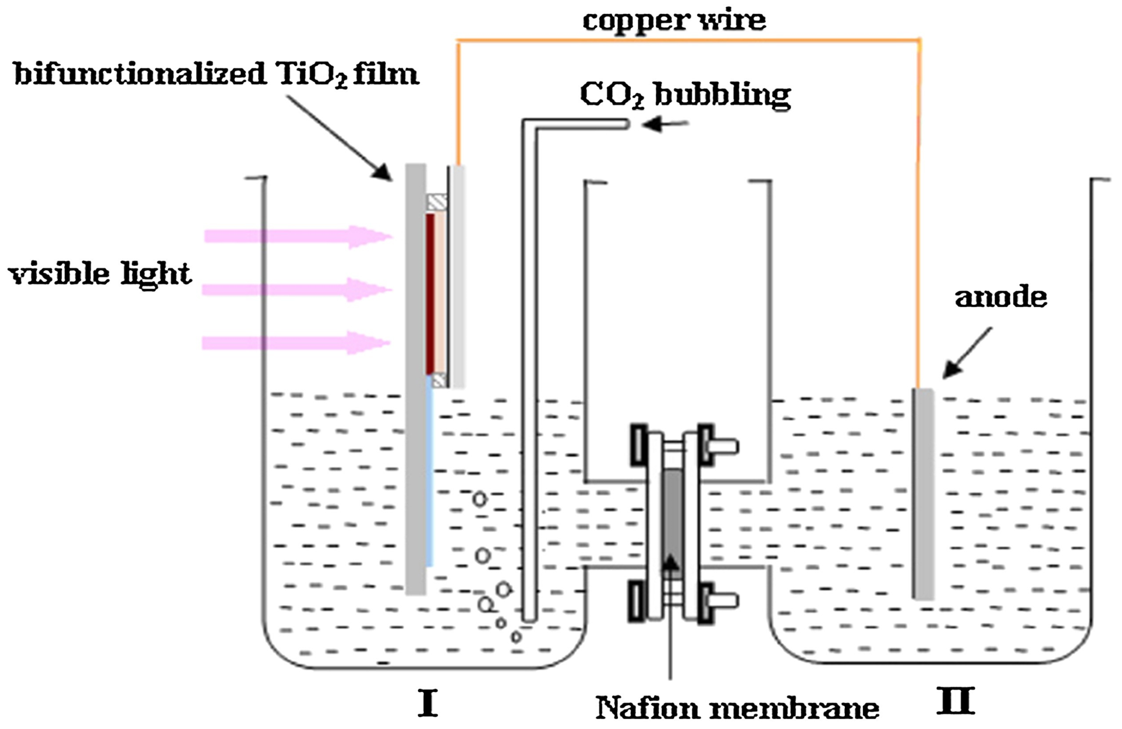
| Twin reactor (membrane photoreactor) | → The reactor system is separated by a membrane, which enables the redox process to occur in a separate compartment | → Higher diffusion and mass transfer among gas as well as liquid phases → Higher conversion efficiency → Higher selectivity → Prevent backward reaction | → Difficulty with CO2 diffusion and electrical conductivity |
| Solar Photoreactor | Solar Energy Efficiency |
|---|---|
| Concentrated reactor system | 0.087–0.15% |
| Slurry photoreactor | 1% |
| Optical fibre photoreactor | 0.0182% |
| Membrane reactor | 0.08–10% |
| Type | Description |
|---|---|
| Reflector | Upon hitting the concentrator, the sun rays will be reflected to the PV cell. Example: Parabolic Trough, Parabolic Dish, CPC Trough, Hyperboloid Concentrator. |
| Refractor | Upon hitting the concentrator, the sun rays will be refracted to the PV cell. Example: Fresnel Lens Concentrator. |
| Hybrid | Upon hitting the concentrator, the sun rays can experience both reflection and refraction before hitting the PV cell. Example: DTIRC, Flat High Concentration Devices. |
| Luminescent | The photons will experience total internal reflection and be guided to the PV cell. Example: QDC. |
| Influencing Parameter | Solar Photoreactor | Parameter and Photocatalyst | Product and Yield | Comments | Reference |
|---|---|---|---|---|---|
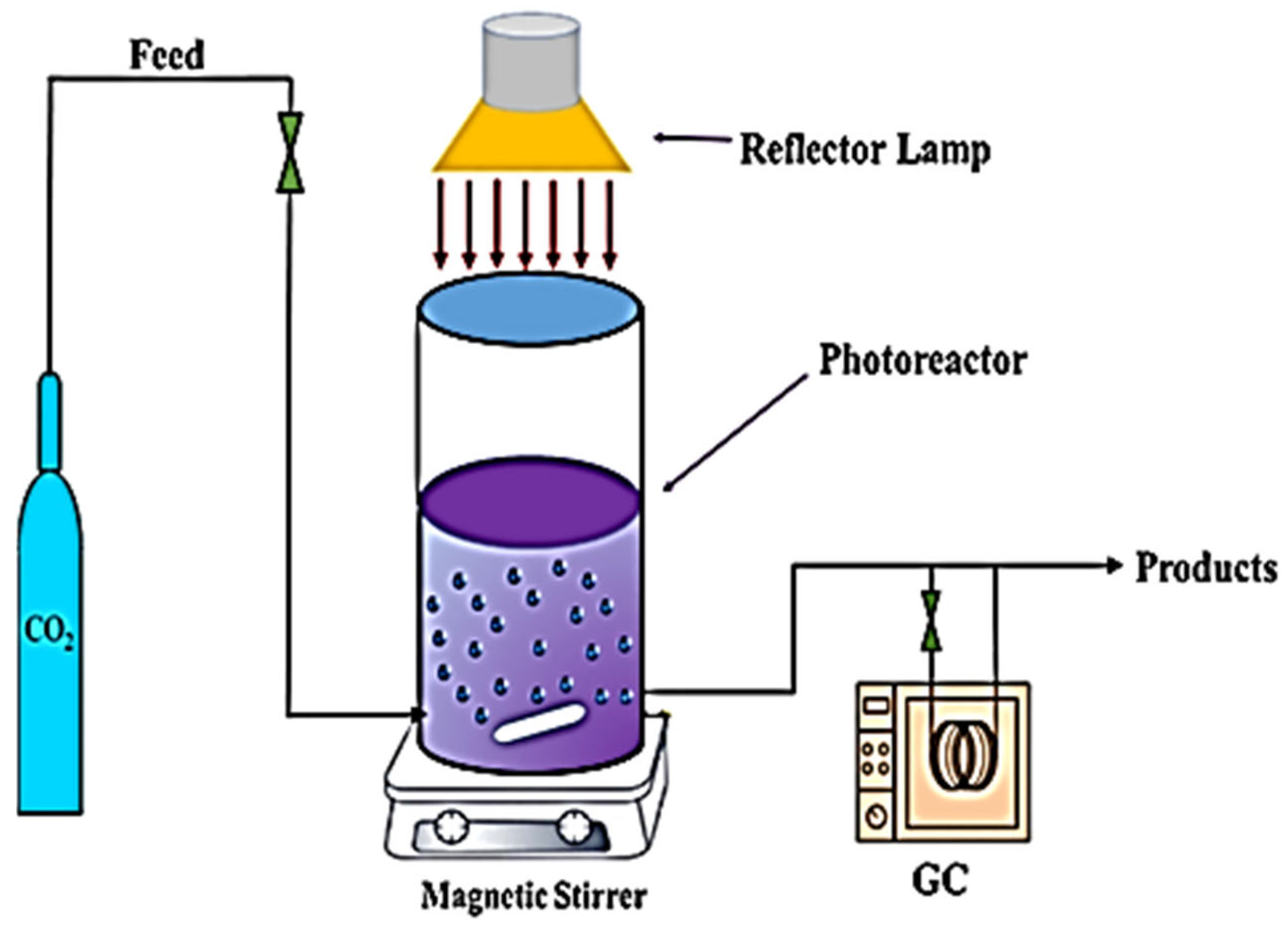
| Reactor configuration | Photoreactor | T = 23 °C, 0.5 g catalyst/300 mL solution; photolyte depth—36.7 mm | Traces of H2 | The catalyst got attached to the reactor windows, which blocked the light irradiation and resulted in low hydrogen production | [128] |
| Modified photoreactor | T = 23 °C, 0.5 g catalyst/300 mL solution; photolyte depth—36.7 mm | H2 = 58 mL/h | Increased H2 production due to the high degree of mixing, avoiding formation of dead zones, particle settlement, and accumulation in the modified photoreactor | [128] | |
| Fresnel lens concentrated solar light photoreactor | T = 659.6 °C, P = 1.1 MPa, CR: −800; 250 mg TiO2 | CH4 = 3157.2 μmol g−1 h−1, C2H4 = 511.5 μmol g−1 h−1; C2H6 = 1346 μmol g−1 h−1; CH3OH = 14.5 μmol g−1 | Incrementing the temperature and pressure of carbon dioxide along with water was enhanced to achieve a 3.94% CO2 reduction | [168] | |
| Twin photoreactor | pH = 2.5; T = 333 K, P = 20 atm | CH3OH = 14.5 μmol g−1 | An increment in the temperature, as well as pressure, is responsible for the gradual rise in the methanol production | [189] | |
| Photoreactor | Irradiance: 40 W m−2; reaction time: 4 h; T = 40 °C | CH4 = 28.5 μmol g−1 | Using low irradiance reaction time and temperature significantly affected methane production | [190] | |
| Operating condition | Solar photoelectrochemical | T = 298 K; pH = 2.5; reaction time: 6 h | HCOOH = 1.55 μM; HCOH = 0.62 μM; CH3OH = 2.02 μM; CH4 = 2.16 μM | Product concentration increased with reaction time | [191] |
| High-pressure photoreactor | T = 85 °C; P= 20 bar | H2 = 51.2 mmol h−1kgcat−1; CH4 = 1.73 mmol h−1kgcat−1; HCOOH&CH3OH = 110 g C h−1kgcat−1 | An increment in pressure favoured the production of liquid products but it showed a decrement in gaseous product formation | [120] | |
| High-pressure photoreactor | T = 90 °C, P = 19 bar; pH = 11.4 | CH4 = 8.5 mmol h−1kgcat−1; HCOOH&HCHO= 110 g C. h−1 kgcat−1 | An increment in pressure favoured the production of liquid products but it showed a decrement in gaseous product formation | [114] | |
| Concentrating solar light photoreactor | Pt/TiO2; CR = 38.2; P = 1 MPa; 7 h irradiation | CH4 = 20.55 μmol g−1 | There is a variation in the methane yield with the concentration ratio as it increased initially, followed by a reduction in the production rate | [131] | |
| Photochemical solar collector | Rectangular plate area = (1 m × 0.5 m); thickness = 3 mm; 40–60 g/m2 of SrTiO3 | HCOOH = 0.273 μmol kJ−1; HCHO = 0.0154 μmol kJ−1; CH3OH = 0.0193 μmol kJ−1 | The overall STC efficiency obtained was low due to the reverse reactions of catalytic oxidation of the organic products on the oxide semiconductors | [188] | |
| CPC photoreactor | Non-truncated type; orientation: east–west; horizontal angle: 25°, CR: 4.22 | H2 = 7.14 L.h−1 | 0.087% of average energy conversion efficiency is reported as more diffuse as well as reflected radiation being absorbed by the CPC photoreactor | [192] | |
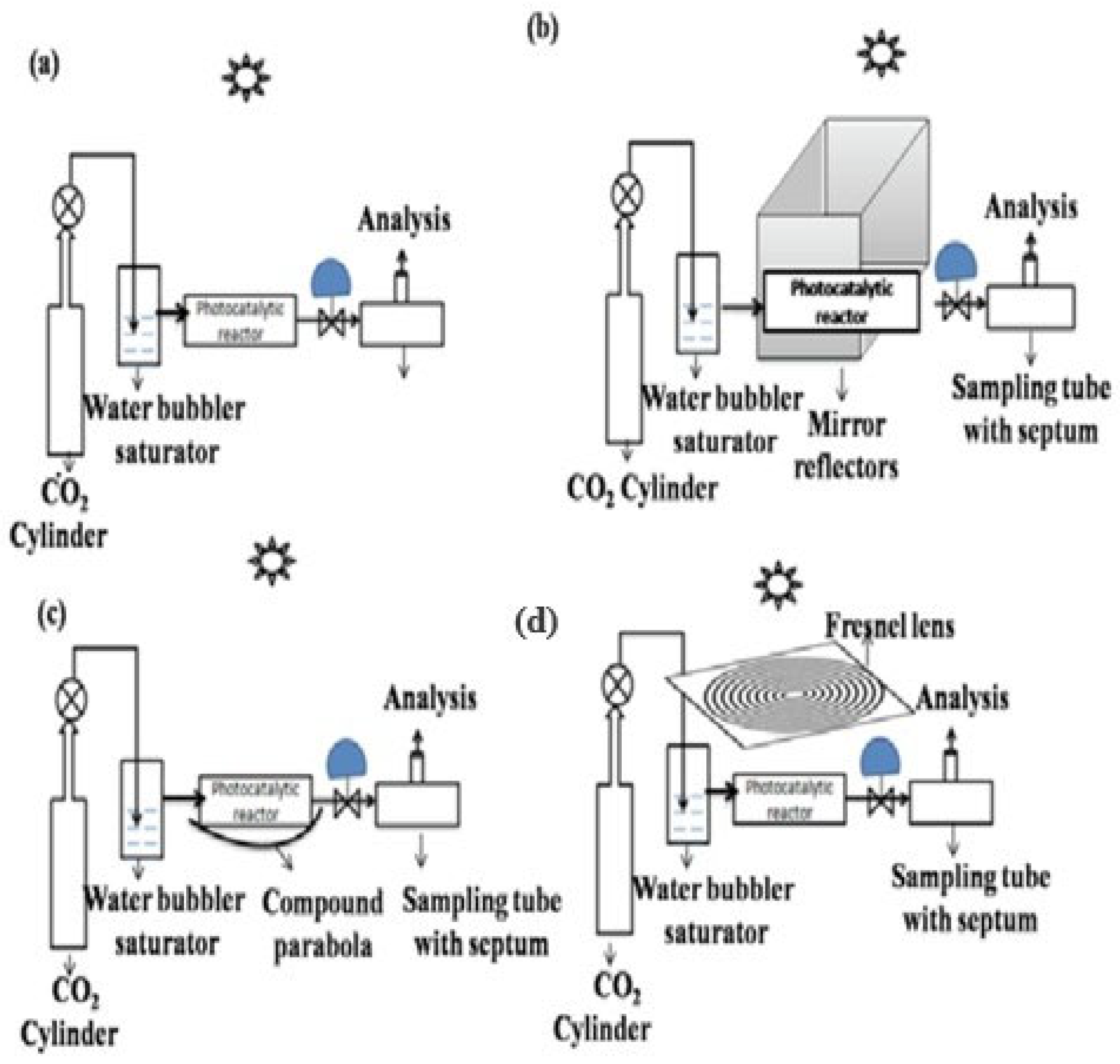
| Solar light concentrator | Solar photocatalytic reactor | Flat sheet mirror reflectors −30 cm × 30 cm; reactor volume: 25 cm3; continuous; reaction time: 1 h; 1 g of CdS catalyst | C2H5OH = 2.6 μmol gcat−1.h−1; HCOOH = 225.7 μmol gcat−1 h−1 | Flat sheet reflectors did not result in greater CO2 conversion to C2H5OH but showed a rise in HCOOH formation rate | |
| Photocatalytic efficiency (PCE) (%) = 0.0005% | |||||
| CO2 conversion efficiency (CCE) (%) = 3.31% | [61] | ||||
| Solar photocatalytic reactor | Compound parabola, 100 mirror strips; width: 1.5 cm; length: 45 cm; reactor volume: 25 cm3; continuous; reaction time: 1 h; 1 g of CdS catalyst | C2H5OH = 24.5 μmol gcat−1 h−1; HCOOH = 777.8 μmol gcat−1 h−1 | Using CPC has increased the temperature in the photoreactor, which has increased product yield, PCE = 0.0024%; CCE = 11.99% | [61] | |
| Solar photocatalytic reactor | Fresnel lens diameter = 8 cm; 560 cm2 area; reactor: 25 cm3; continuous; reaction time: 1 h; 1 g of CdS/MnO3 catalyst | C2H5OH = 52.2 μmol gcat−1 h−1; HCOOH = 1392.3 μmol gcat−1 h−1; H2 = 2766 μmol gcat−1 h−1 | High product yield, PCE = 0.195%; CCE = 23.08% | [61] |
Disclaimer/Publisher’s Note: The statements, opinions and data contained in all publications are solely those of the individual author(s) and contributor(s) and not of MDPI and/or the editor(s). MDPI and/or the editor(s) disclaim responsibility for any injury to people or property resulting from any ideas, methods, instructions or products referred to in the content. |
© 2024 by the authors. Licensee MDPI, Basel, Switzerland. This article is an open access article distributed under the terms and conditions of the Creative Commons Attribution (CC BY) license (https://creativecommons.org/licenses/by/4.0/).
Share and Cite
Degerli, S.N.; Gramegna, A.; Tommasi, M.; Ramis, G.; Rossetti, I. Reactor and Plant Designs for the Solar Photosynthesis of Fuels. Energies 2024, 17, 3112. https://doi.org/10.3390/en17133112
Degerli SN, Gramegna A, Tommasi M, Ramis G, Rossetti I. Reactor and Plant Designs for the Solar Photosynthesis of Fuels. Energies. 2024; 17(13):3112. https://doi.org/10.3390/en17133112
Chicago/Turabian StyleDegerli, Simge Naz, Alice Gramegna, Matteo Tommasi, Gianguido Ramis, and Ilenia Rossetti. 2024. "Reactor and Plant Designs for the Solar Photosynthesis of Fuels" Energies 17, no. 13: 3112. https://doi.org/10.3390/en17133112
APA StyleDegerli, S. N., Gramegna, A., Tommasi, M., Ramis, G., & Rossetti, I. (2024). Reactor and Plant Designs for the Solar Photosynthesis of Fuels. Energies, 17(13), 3112. https://doi.org/10.3390/en17133112