Abstract
The paper relates to the development of an algorithm applicable for maintaining the rotational speed of low-speed drives using PMSM motors and operating under a sign-changing load. The moment of inertia of rotating parts does not play the role of a mechanical stabilizer for the speeds discussed in the article. Simulation studies are presented with the aim of developing a rotational speed control algorithm that utilizes only positional feedback and the previously assumed sign-changing load on the shaft. For the purposes of this research, a mathematical model was developed to calculate transient processes in a PMSM machine operating in the conditions of a sign-changing load on the shaft. This model assumes a deterministic control principle adapted to the known nature of the load change. In this model, the mutual influence occurring between the phase fluxes, the electromagnetic torque, the electric currents and the rotor position angle are established on the basis of FEM analysis of a two-dimensional magnetic field using a quasi-stationary approximation. Principles applicable for controlling a direct low-speed servo drive based on a PMSM machine operating with a known variable shaft load using only positional feedback and a predetermined shaft load change law are defined. The proposed regulation method is verified in an experimental manner. For this purpose, an experimental setup was built, which includes a PMSM with a load imitator on a variable sign shaft, an inverter providing sine-shaped power supply to the machine and a digital dual-processor control system. The discussed rotational speed stabilization algorithm was implemented in the form of a program for a microcontroller, which forms a part of the control system. The results of experimental tests confirm the adequacy of mathematical modeling and the effectiveness of the proposed rotational speed stabilization algorithm.
1. Introduction
Synchronous machines comprising permanent magnets, which according to international terminology are known as PMSMs (permanent magnet synchronous motors), are widely found in servo drives in various industrial purpose applications, electric transport, in metal processing machines, etc. As a consequence of their relative high energy and reliability parameters, like small inertia and low noise level, such machines provide a suitable alternative for other types of electric machines [1].
PMSM forms a system characterized by considerable, usually nonlinear electromagnetic relationships. When PMSM is applied in actual industrial conditions, its parameters are not constant and can vary within a certain range, depending on the variations in the parameters of the working environment–shaft torque and rotational frequency. The fluctuations of these values within the abovementioned range may be unacceptable from the viewpoint of the required level of stability and operational safety of the entire system. Therefore, the dynamics of PMSM operation in various operating modes and the stability conditions must be clearly defined, at least for the theoretical justification for employment of a PMSM-based drive [2].
It should be emphasized that PMSM are understood to be machines designed to operate with a sinusoidal voltage or current source, whose initial phases and frequency are relative to the angle of rotation of the rotor.
2. Analysis of Current Research on PMSM
Contemporary scientists have carried out extensive research into the dynamic characteristics and stability of the systems that include a PMSM in their design in order to enhance the precision of control of PMSM systems.
A typical solution to the problem of stabilizing the rotational frequency of direct drives with PMSM motors includes the application of controllers with multiple feedbacks, mainly applied for control of position, rotational speed, current or torque [3,4,5,6]. However, in the cases when variable loads are applied, in particular in the conditions marked by a relatively large moment of inertia, problems that arise can include accurate positioning and reducing frequency pulsation [3]. Some attention is also paid to the low effectiveness of the drive when specific control laws are applied in the process [7].
For the purpose of improving the quality of regulation of PMSM systems, we can use genetic algorithms, among other solutions [4]. In addition to the encoder, fuzzy logic algorithms [8] can be utilized for the purposes of accurate determination of the rotor position, which can also increase the accuracy of determining the current value of the rotational frequency. In the study reported in [9], a bee swarm optimization algorithm has been applied to determine the controller gain factors. An enhanced version of the adaptive PID controller for regulating and stabilizing rotational frequencies and a simple algorithm for searching for gain coefficients were proposed in [6]. The authors of [10] investigate the application of PMSM machines as oscillatory systems and define the areas of stable operation in the linear region of their operating parameters.
The study in [11,12] applies dedicated observers to assess the gain factor of the control inputs and the level of interference for unspecified values of the moment of inertia, the Magnetic flux coupling of the stator winding and the load on the shaft. The proposed approach enhances the rotational speed tracking performance and, consequently, the operational properties of the drive in general.
The current problem related to increasing the efficiency of PMSM rotational frequency control in motor mode is analyzed in [13]. A controller structure is proposed that tracks system slippage using special algorithms and minimizes it in an original way. A similar approach is applied for the control of a PMSM motor that does not contain a rotor position sensor [14]. The research reported in [15] also utilizes slippage for the control of the position of a kinematic system under a load-changing sign on the shaft, operating in real time and driven by a DC commutation motor. In this case, an industrial servo controller is used.
Rotor position sensors of various designs are an invariably important component of servo drives. Due to the fact that the sensors are an indispensable element, the authors [16] implemented the rotational frequency stabilization function.
The operation of a motor in a pump assembly or compressor unit is considered a default example of a cyclically variable load [7,17]. In such applications, the law of load change on the shaft is deterministic and can be derived as a function of the rotor position angle. The study in [17] emphasizes the relevance of energy-efficient control with the possibility of adjusting the rotational frequency in a wide range and the need to minimize velocity pulsations in the steady modes of such units.
The complete vector control for six-phase PMSMs is investigated in [18]. The ability to directly control the electromagnetic torque and rotational frequency is ensured by the presence of feedback on the rotor position, the current and EMF or alternatively magnetic flux. Dual three-phase PMSM motors were considered in [19,20] as machines with potentially improved control performance for use in low-speed drives. Another vector control system for the PMSM drive with a rotational frequency control strategy was proposed in [21]. This study employs the determination of the phase components of currents in a rotational coordinate system and ensures high dynamics of the controlled motor, thus minimizing output torque pulsations and significantly reducing harmonic deviations of phase currents.
Particular focus in the research is given to the development of effective methods of controlling motors with internal location of magnets on the rotor, the so-called IPMSM, which are characterized by a ratio of the inductive parameters of the stator winding that does not follow traditional guidelines. In the study reported in [22], a method is applied to determine these parameters is proposed, which enables automatic adjustment of the control system, significantly expanding its functional capabilities. The authors of [23] created a speed controller for IPMSM based on a torque observer. It provides a fast dynamic response and lower steady-state error compared to a classic integral-proportional controller in the event of changes in system parameters and torque disturbances. The regulator is implemented using an efficient, integrated controller based on a digital signal processor (DSP).
In addition, variable load regimes are applied in the diagnostics of faults in PMSM machines. In [24], this is executed using neural networks, and the FFT analysis is applied for these purposes on the basis of the study in [25].
A review of the research carried out on PMSM machines in variable load modes demonstrated the existence of the following current problems. The change in a load can lead to dynamic instability, characterized by swinging or fast oscillatory processes. This may be due to system imbalance, load peaks, or other factors. To achieve the optimal efficiency and performance of a system containing PMSM in variable load modes, it is necessary to solve the problem of finding the optimal operating regimes and the optimal means of control. Variable loads can lead to electromagnetic interference and electrical noises (vibrations) that may affect the normal operation of the control system. To ensure adequate system response to variable load and ensure its stable operation, the adaptive control problems need to be solved. To ensure reliable operation of the PMSM system in these regimes, real-time diagnostics and predicting the condition of this system may sometimes be necessary to detect potential problems and avoid emergency situations.
In order to overcome the abovementioned challenges a comprehensive approach needs to be adopted. The comprehensive solution should include accurate control, adaptive strategies, technical solutions applicable to reduce the effect of dynamic loads and the improvement of diagnostic systems.
The majority of the above research tasks focuses on improving their quality and effectiveness of controlling rotational speeds in the constant or variable motor operating modes. The operation of drives based in the generator regime is mentioned in [23] but is not further explored.
The available literature does not contain any studies on PMSM load modes with periodic torque, the sign of which changes during one complete revolution of the rotor.
Problem Statement
The operation of PMSM machines as parts of servo drives usually requires a complete vector control system with feedback including rotor position, rotational speed, currents, shaft torque and voltage. However, we sometimes face circumstances when the drive requirements are less stringent and the use of all types of feedback is unfeasible from a technical, economic or another point of view. Suitable examples include direct drives of industrial manipulators, tracking systems, drive systems that operate under variable load on the shaft, with relatively low dynamic torque, and those that do not require accurate stabilization of rotational speed.
The rotor position sensor, also termed the encoder, forms an integral element of such systems. This provides the phase-locked loop (PLL), supply voltage depending on its value and the load. The proposed research intends to verify the potential for implementing the rotational speed stabilization function in systems with a given set law of load change on the shaft, using only information derived from the encoder. Stabilization of the rotational speed will be achieved by changing the amplitude of the supply voltage in the engine mode and the amount of electrical load in the generator mode.
The objectives of the research are to execute an analysis of the structure and development of laws guiding the control of a direct, low-speed servo drive based on a PMSM machine operating under a variable load on the shaft, using only position feedback and the previously known laws of changing the load on the shaft.
The subject of study is electromechanical energy conversion processes in a permanent magnet synchronous motor, powered by a three-phase system of sinusoidal voltages, whose phases are relative to the angular position of the rotor.
In our opinion, this research goal needs to include the development of an adequate mathematical model of a PMSM machine, as well as the execution of appropriate mathematical experiments and confirming the functionality of the developed control principles in an experimental manner.
3. Mathematical Model of PMSM
A mathematical model was developed for the purpose of calculating transient processes in a PMSM machine operating under a variable load on the shaft. This model takes into account the laws of controlling the amplitude of the supply voltage and the magnitude of the electrical load, which, if necessary, are adjusted to any nature of the change in the mechanical load.
The mathematical formulation of this task required that a number of assumptions were taken into account. The magnetic field of the machine (magnetic vector potential field) was considered in a quasi-stationary approximation and was considered to be two-dimensional. The finite element method using specialized Ansys Multiphysics R16.2 software was applied for the calculations.
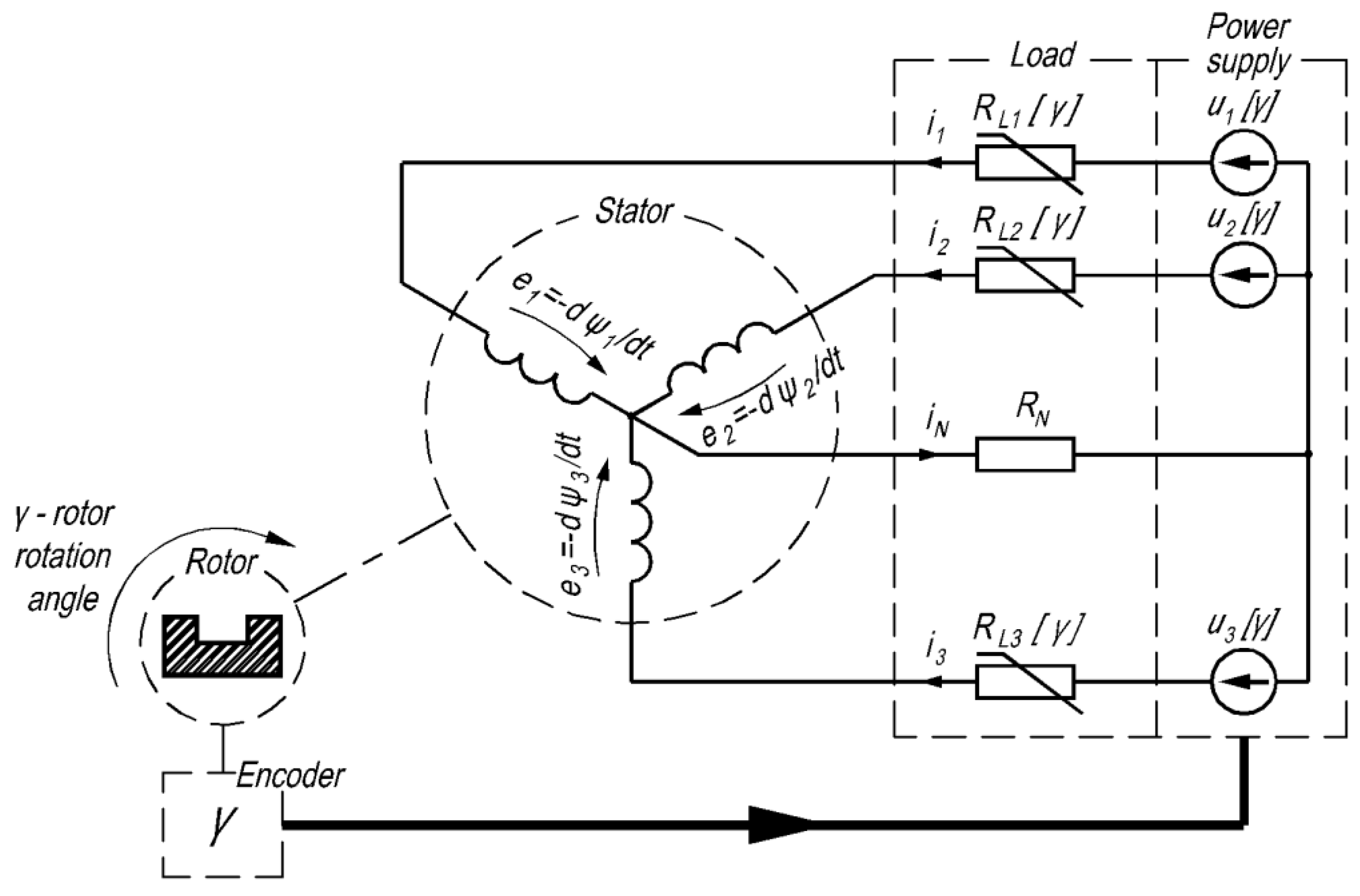
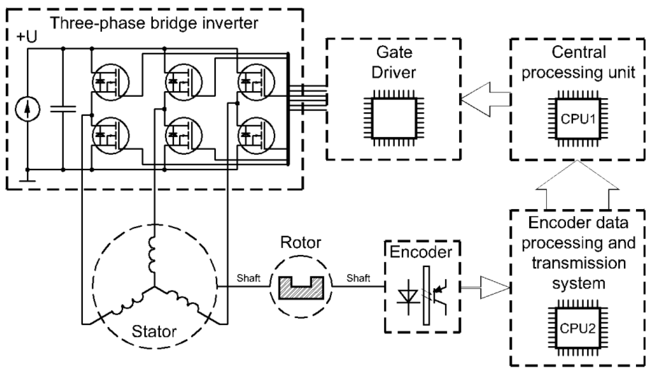
The schematic diagram of the PMSM control system is shown in Figure 1. It contains an idealized three-phase sinusoidal voltage source with PLL. In real systems, voltage is typically generated using an electronic pulse width controller (PWM). Figure 1 also contains a block diagram of the load in the form of three resistances connected in series with the PMSM phase windings. The value of these resistors is relative to the rotor position angle. In the physical prototype of such a control system, the function of these resistors is performed by PWM-controlled transistors in accordance with the established law. The load structure block also enabled the study of the system’s generator modes, thus extending the functionality of the proposed mathematical model.

Figure 1.
Diagram of PMSM control system.
We took into account that most schematic solutions of similar systems include a 4-wire interface applied for connecting the machine to the power supply system. For this purpose, a ‘neutral’ conductor was connected. To consider 3-wire systems—resistance was assumed to be .
Despite the fact the research object adopted a relatively high level of idealization, the assumptions excluded the need to execute a mathematical description of semiconductor elements forming the part of power supply circuits, which consequently increased the computing rate of the numerical algorithm applied for integrating the Algebraic and Differential System Equations for transient processes in PMSM. On the other hand, by determining the magnetic state of the machine using Maxwell’s equations, it was possible to take into account the most important factors that influence the course of electromechanical processes, both static and dynamic in similar electromechanical systems, such as the PMSM. For example, the saturation of the magnetic circuit, the actual harmonic composition of the magnetomotive force (SMM) of the PMSM armature winding, the higher harmonics of tooth-order SMMs, the magnetic anisotropy of the inductor poles in two spatial coordinates and the cogging moments caused by the explicit polarity of the PMSM magnetic circuit structure were taken into account.
3.1. Mathematical Notation
The set of equations that describe the processes in PMSM operating in the motor and generator regime comprises the electrical balance equations as follows:
Formulae that describe the instantaneous supply voltages, independent of the rotor position angle γ:
Expressions representing the resistance of the load:
Magneto-mechanical characteristics [19] represented by the relations between the magnetic flux coupling and electromagnetic torque and currents and rotor position angle:
Expression for the steady state torque for the case of a sign-changing load on the shaft:
Mechanical balance equation and a formula that represents the rotational frequency:
where —active resistance of the stator winding phases in PMSM and of the neutral wire;
, , —phase voltage of the supply;
—voltage phase shifts;
, , , —stator phase currents and in the neutral wire current, respectively;
—phase flux coupling of PMSM phases;
—electromagnetic torque of PMSM;
—angular speed of PMSM;
, , —supply voltage amplitude, load resistance and steady-state load torque as a function of the rotor position angle γ (the specific plot of these functions, taking into account the characteristics of the investigated PMSM machine that forms the subject of the physical experiment, is analyzed later, at the stage of developing the model algorithm);
—number of pole pairs.
It should be noted that the magnetic-mechanical characteristics (MMCh) of machine (4) is determined based on the solution of the electromagnetic field equations in a two-dimensional term.
Algebraic System Equations (1)–(6) comprise 17 scalar equations and include the same number of scalar unknowns: along with the initial condition and in general, they represent the contents of the Cauchy process.
The following notations were applied for the possible transformation into the vector notation:
—column vector of phase currents;
—column vector of the complete magnetic flux coupling in the stator circuits;
—column vector of supply voltages;
—diagonal matrix of active phase resistances and load resistance;
—column describing the active resistance of the neutral wire;
, –coordinate matrix and row.
The Algebraic System Equation is written (1)–(6) in the matrix form:
The vector Algebraic System Equation (7) contains 9 unknowns:
3.2. Algorithm Applied for the Task Solution
Prior to developing our algorithm, let us determine the functional dependencies of the driving forces and loads on the rotor position angle, taking into account the specific conditions of the physical experiment.
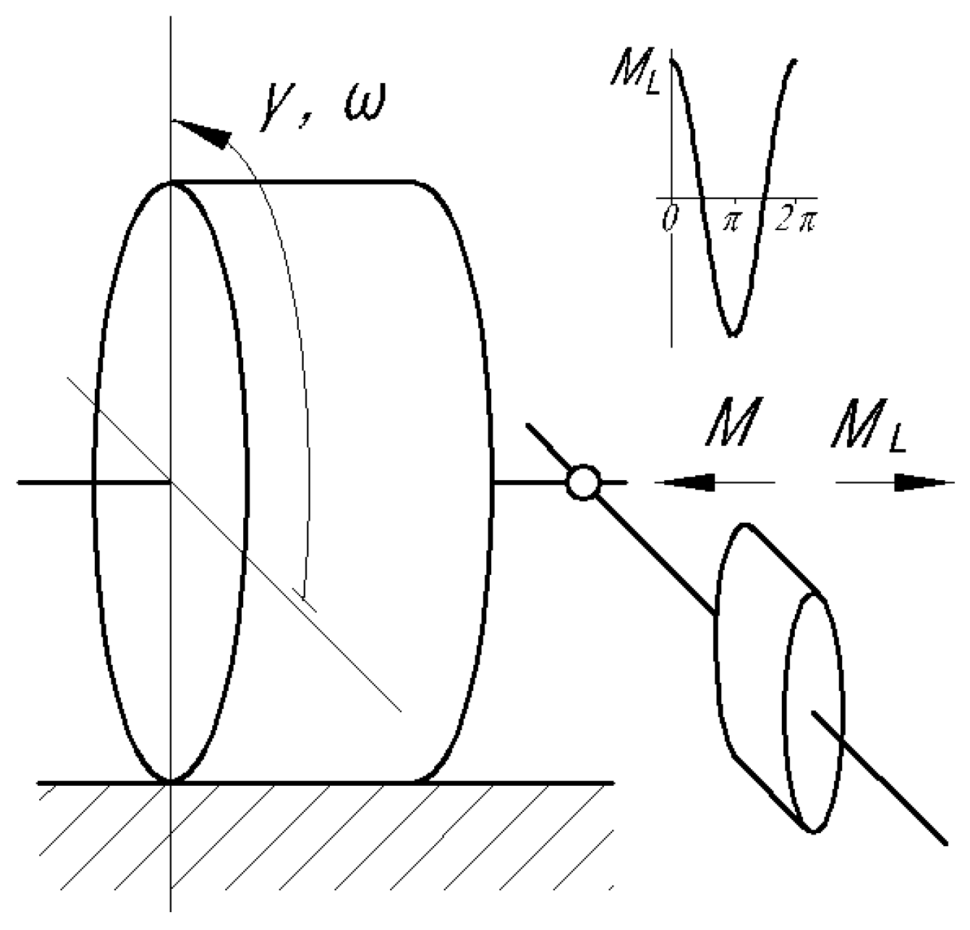
In particular, the law of changing the mechanical load on the shaft (5) is mathematically formalized by the expression
which is derived from the design of the device that acts as the load (Figure 2).
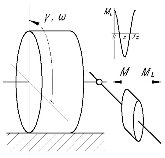
Figure 2.
Principal load diagram.
The law guiding the changes in the supply voltage amplitude for the characteristic load (8) was defined in the following form:
where , —maximum and minimum values of amplitude;
–angle that shifts the instant of initiating/closing the supply voltage and switching to the generator regime.
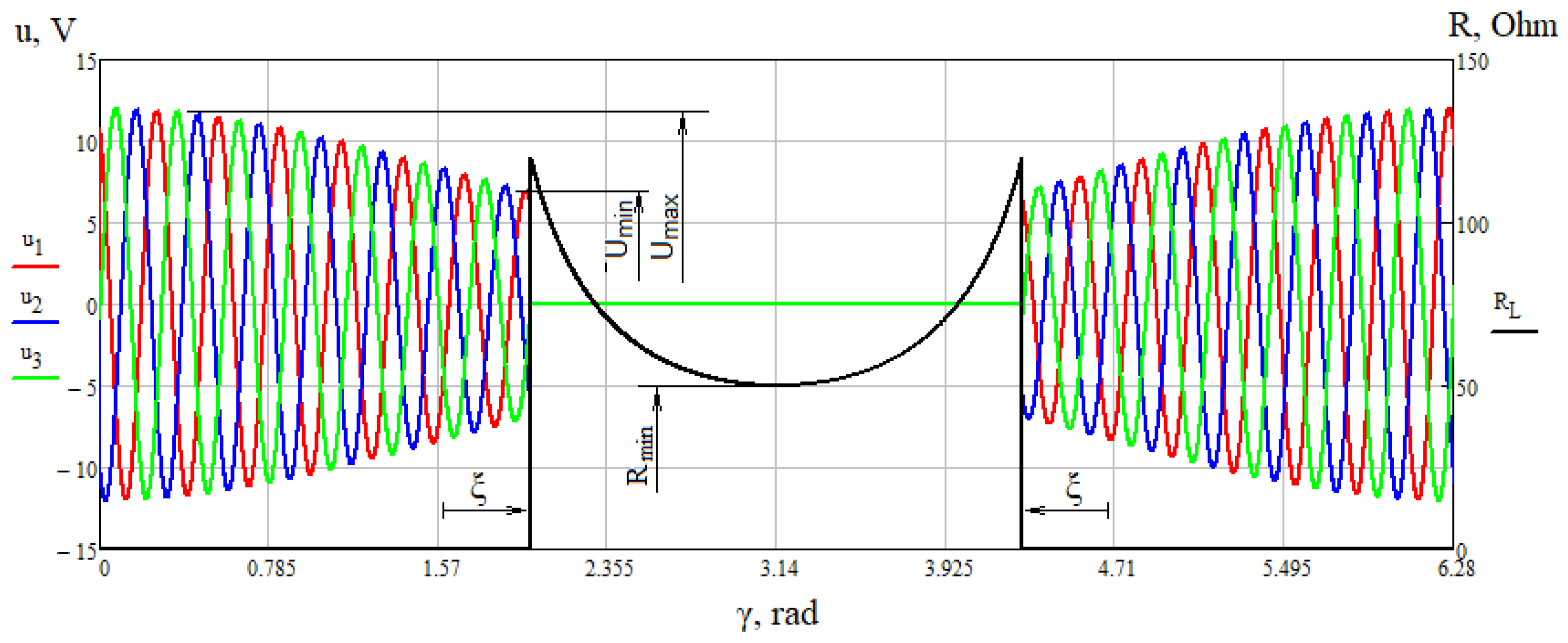
The form of the Function (2) taking into account (9) for and is presented in Figure 3.
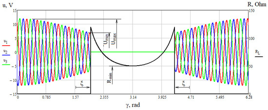
Figure 3.
Dependencies of the three-phase supply voltage system and load resistance on the rotor position angle.
The function of the resistance to load is in (3):
where –minimum value of resistance.
For , the function in (10) is presented in Figure 3.
Following the stage when the derivatives in (7) take algebraic form using the g-th order Gir method, the system of nonlinear algebraic equations representing the k-th step of integration takes the form
where —values of unknowns at the k-th step of integration; —values derived from the preceding step of integration.
The system of equations in (11) is non-linear due to the occurrence of non-linear dependencies corresponding to the characteristics of magnetic-mechanical characteristics (MMCh) of the machine, resistances and load torque on the rotor rotation angle. Newton’s iterative method was utilized to solve it. The linear Algebraic System Equations, induced by the system of non-linear Equation (11) on the l-th iteration of Newton’s method, takes the form
where —values of correction of the unknowns along the l-th iteration od k-th step of integration;
values of derivative of MMCh calculated on the basis of (l-1)-th approximation of the unknowns;
the derivatives of the supply voltage over the rotor angle calculated on the basis of (l-1)-th approximation of the unknowns for , elements in (14) are as follows:
for all other rotor angles .
the derivative of the load resistance over the rotor angle calculated on the basis of (l−1)-th approximation for is
for all other angles of the rotor, ;
the derivative of the load torque over the angle of the rotor derived from (l − 1)-th approximation is
the deviations of the standard equations in (12) are calculated from (l − 1)-th approximation of the unknowns.
We can remove the expressions whose deviations are equal to zero from (12).
The linear Algebraic System Equation, which has been developed taking into account the corrections for the circuit currents and angle of the rotor position, needs to be solved along the l-th iteration of the Newton method and takes the following form:
Therefore, to perform the k-th step of integration, it is necessary to perform the following steps:
- Development of constants in the matrices and matrix .
- Calculation of the value of the deviation (18) for (l − 1)-th approximation of the root.
- Calculation of the values of derivatives (14)–(17) and magneto-mechanical parameters for (l − 1)-th approximation of the root.
- Calculation of the elements of the coefficient matrix and right-hand column of the right-hand linear URA (20).
- Solution of linear URA (20) in respect to the values of the corrections .
- Calculation of l-th approximation of the unknowns using the following formulae:
- Calculation of remaining unknowns by means of the formulae:
If the accuracy of determining the unknown corrections is insufficient, steps 2–7 need to be repeated. Otherwise, we can proceed to the next integration step.
The proposed algorithm is implemented in the form of a computer program in the Ansys environment using APDL (Ansys Parametric Design Language).
4. Mathematical Experiments
The mathematical experiments were carried out using a PMSM servo motor. The dimensions, winding data and parameters of this motor are provided in Table 1 and they represent the data of our developed prototype, which were later used in the physical experiments. The moment of inertia of the rotating machine parts was reduced by ≈2.5 compared to the physical prototype, which made it possible to accelerate simulation results in regimes similar to the established ones (). For modeling a three-wire supply system, the active resistance of the ’neutral’ wire was set at a level of Ohm, (see Figure 1).

Table 1.
Technical parameter of the prototype applied in laboratory.
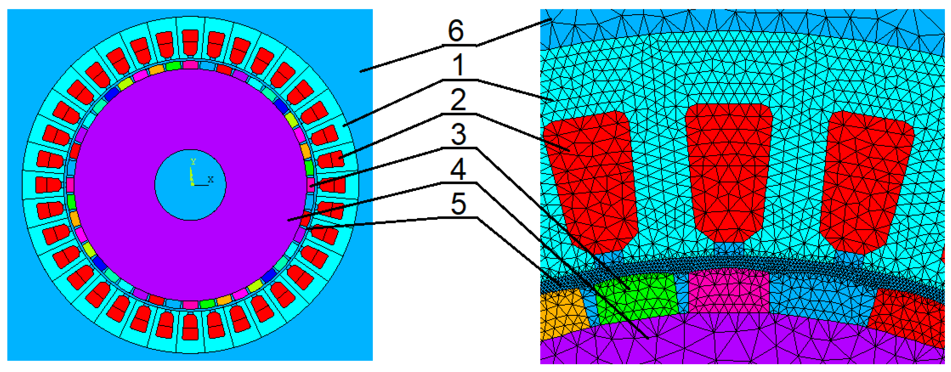
The two-dimensional computational domain applied for the magnetic field using the finite element method, constructed based on the dimensions given in Table 1, is shown in Figure 4. Note that areas of the same color have identical magnetic properties.
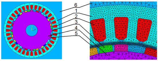
Figure 4.
Computational domain and section and finite element mesh: (1) stator core; (2) winding; (3) pole; (4) rotor core; (5) air gap; (6) environment.
The results of the magnetic field calculations for one of the MMCh points, namely for , , and are presented in Figure 5.
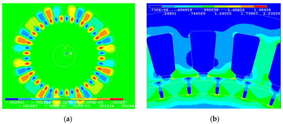
Figure 5.
Characteristics of magnetic field in the investigated servomotor: (a) magnetic vector potential field, ; (b) distribution of magnetic field induction vector module, T.
Even a superficial analysis of the obtained images allows us to conclude that in this state, the machine is slightly saturated, so the electromagnetic relationships (between currents and the magnetic flux coupling) are practically linear.
In the first step, the operating mode of a PMSM powered by a three-phase sinusoidal voltage source was examined. The phases of these voltages and the load torque depended on the rotor rotation angle (2) and (8). The voltage amplitude in this test was constant, and the connection of an additional load in generator mode was not projected.
In Figure 6, we can see the time relations of the phase values of voltage, emf and current in the engine mode (on the left) and in the generator mode (on the right). The range of rotor angular positions in these modes is equal to and , respectively. On the basis of this figure, we conclude see that phase current is delayed in relation to emf by a slightly greater value of π rad el. in the motor regime, while in the generator regime, it precedes emf by o rad el.
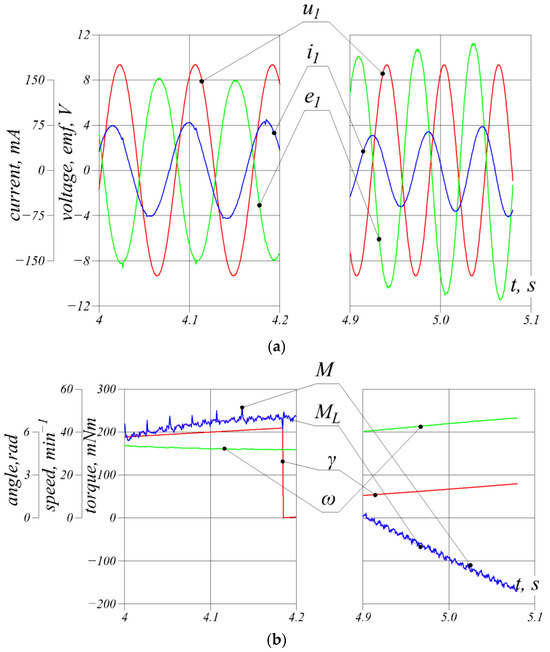
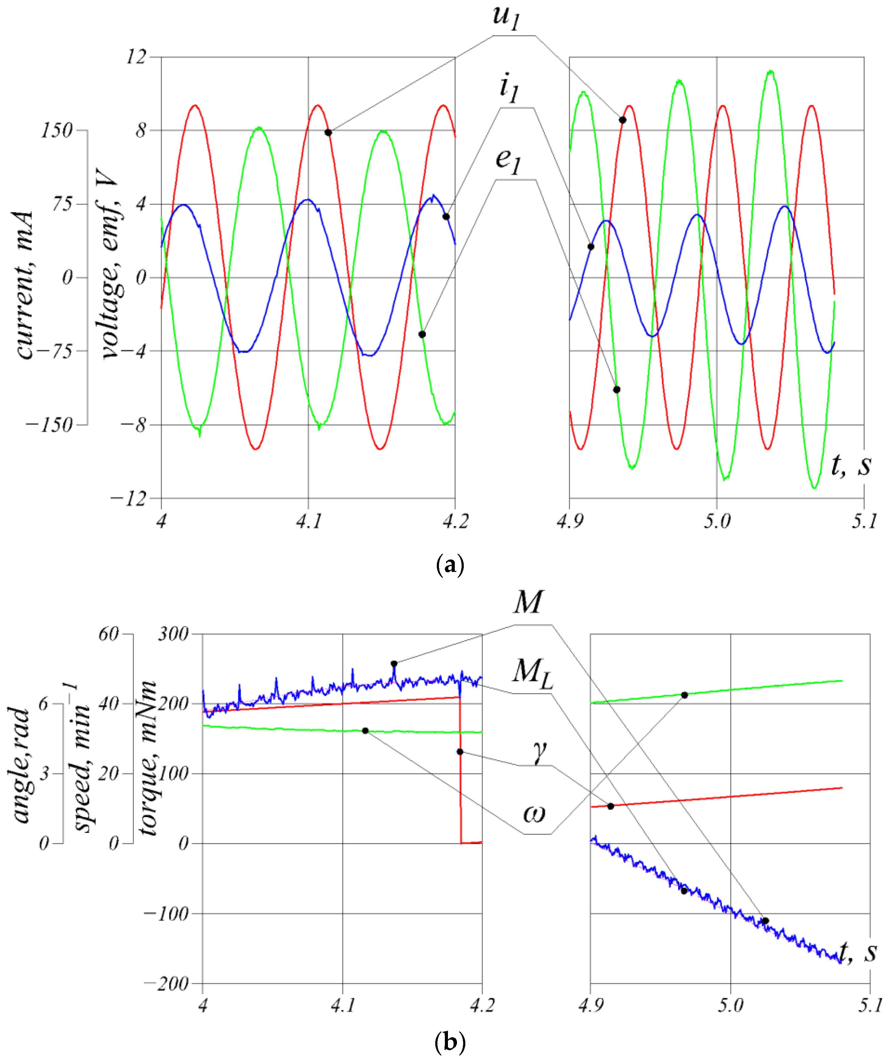
Figure 6.
Time relations of the values without speed regulation of (a) phase voltage , SEM and current (b) rotor position angle , electromagnetic torque , load torque and rotational frequency .
These phase shifts vary during a single revolution, and this forms a typical characteristic of the performance of the machine under a variable load. Switching to generator mode is associated with an increase in the value of emf. It is then greater than the phase voltage. It is also noticeable that the torque pulsations of tooth frequencies in the engine mode are larger than in the generator mode. This is due to the reduction in the amplitude of the stator current in generator mode due to the reduction in the difference between emf and voltage. At the same time, the amplitudes of the magnetic flux linkages remain virtually constant. The braking effectiveness of such a drive can be sensibly regulated by fully disconnecting the phase voltages. The change in braking torque by changing the resistance of the armature circuit, in this case, will occur over a wider range of values. In a physical experiment, this regime was implemented by changing the PWM duty cycle for the ’lower’ keys of the semiconductor bridge with the ’upper’ keys turned off.
The subsequent mathematical experiment concerned the same servo motor, but the amplitude of its supply voltages and additional active resistances in the stator winding circuits were relative to the rotor position angle (9) and (10).
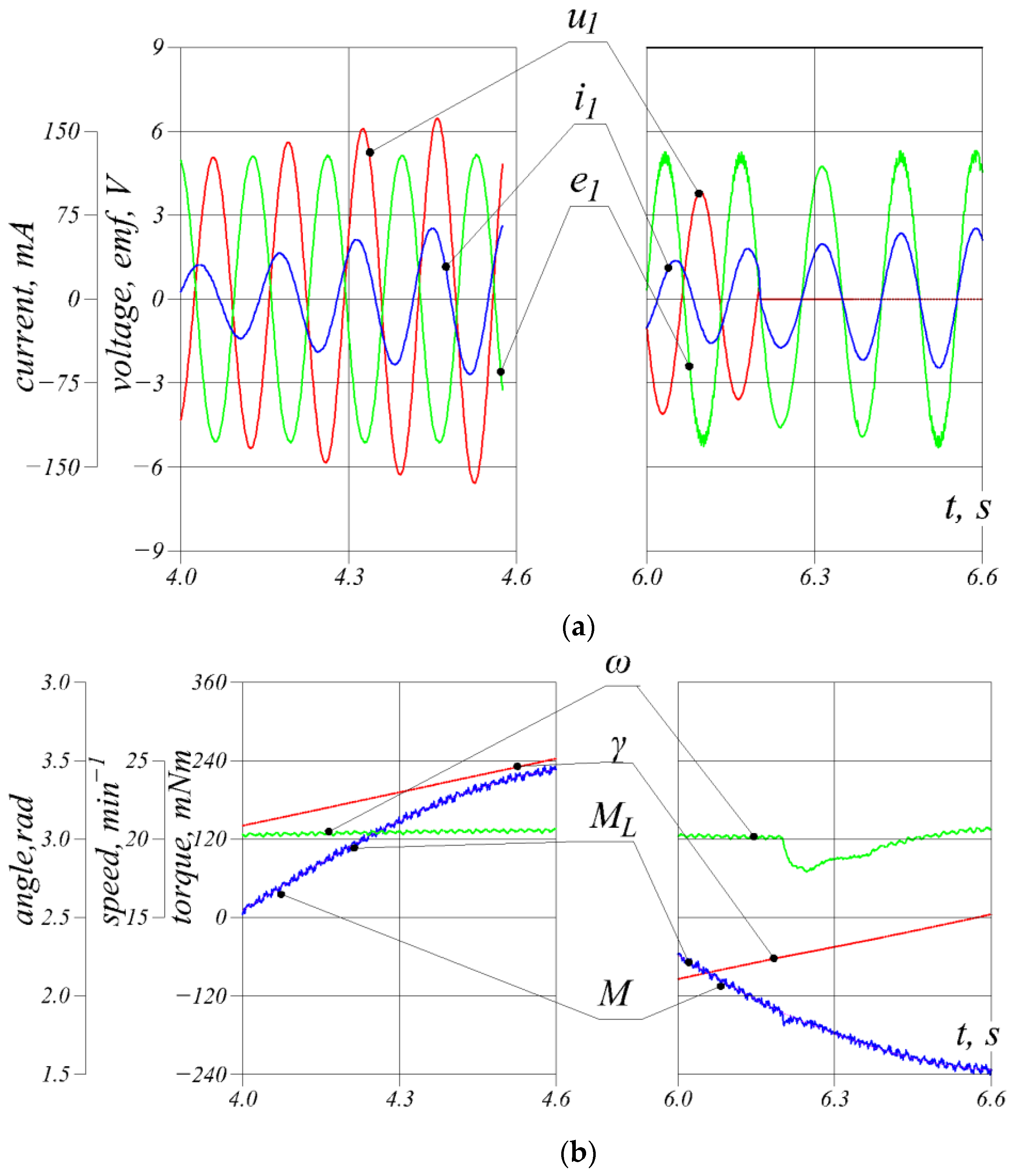
A summary of the major main results gained as a result of such an experiment is provided in Figure 7.
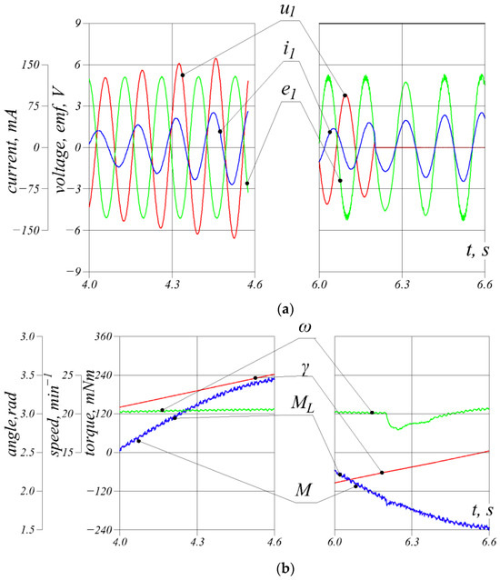
Figure 7.
Time relations of operational values with speed regulation of (a) phase voltage , SEM and current (b) rotor position angle , electromagnetic torque , load torque and rotational frequency .
The transition of the machine to the generator regime occurs at the rotor rotation angle equal to . The emf value for this position is smaller than the voltage. For this angle, the amplitude is only 70% of the maximum value . The stator current is also relatively small and practically corresponds to zero shaft torque. When the supply voltage is disconnected and simultaneous coupling of resistors in each phase occurs, an excessive braking torque will be generated and the rotor will stop close to this position. Therefore, after reaching the angular position , we continue to boost the rotor with the electromagnetic torque in the direction of its rotation until the rotational speed begins to increase slightly due to the negative load torque on the shaft. Subsequently, we set the phase voltages to zero, which corresponds to a short circuit of the machine’s phase windings, and at the same time, we turn on the active resistors that are connected in series to these windings (see Figure 1). In this experiment, the sign of the electromagnetic moment switches at an angle of ≈2.2 rad. The value of the resistance at this point is about one and a half times greater than the value that appears in (10). Similarly, the return from generator mode to engine mode is made in advance of the angular position at which the moment on the shaft changes sign (8).
In the conducted mathematical experiment, the rotational frequency pulsation is equal to approximately 11% per single full revolution. By adjusting the switching angles of the engine/generator operating mode and the resistance values and , such a pulsation can be reduced to 5–7%, in our opinion. Its value is affected by many factors, including the so-called cogging torque of the rotor, which is formed as a result of the attraction of ferromagnetic elements of the stator tooth layer and rotor poles and caused by dimensional errors in the production of such machines (eccentricity, mismatch of axes, etc.); friction moment in bearings, which is not linearly dependent on the rotation angle and rotational frequency; higher time harmonics in the supply voltage, etc. All these factors are virtually insensitive to deterministic modeling. Therefore, in order to confirm or refute the statement regarding the possibility of reducing rotational frequency pulsation, it is necessary to conduct appropriate physical experiments using the proposed regulation law.
5. Description of Laboratory Setup
The laboratory setup, shown in Figure 8, consists of a regulated DC source, the motor subjected to testing and a control system that includes an inverter with PWM voltage capability and a PLL feedback system.
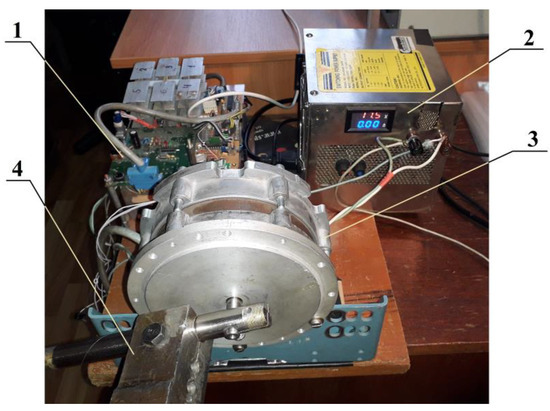
Figure 8.
Laboratory setup designed to research PMSM motor under variable load: (1) PLL inverter; (2) DC source; (3) PMSM motor; (4) variable load imitator.
The investigated motor has two output shafts. A rotor position sensor is mounted on one of them, and on the other one, there is a load imitator with a variable sign in the form of an unbalanced mass placed on a lever attached to this end.
The inverter assembly was designed according to a three-phase bridge system made dedicated to MOSFET transistors. The inverter is controlled by the central processor CPU1 based on feedback signals regarding the current value of the rotor rotation angle received from the position sensor. The main functions performed by CPU1 are as follows:
- Registration of the absolute discrete value of the rotor rotation angle, checking the correctness of this value and converting it into electrical degrees;
- Controlling the duty factor of the three-phase PWM voltage according to the current discrete value of the rotor position angle;
- Conversion of the control signals of the upper tier–‘START’, ‘STOP’, ‘REVERSE’, etc.
Voltage PWM is based on two counters that are part of the CPU1 microcontroller. Six driver outputs, whose state is controlled by counter registers, directly connected to the transistor gate driver microcircuit.
An incremental encoder plays the role of the rotor position sensor, i.e., a device that encodes the relative position of a rotating part using the appropriate number of electrical pulses. These impulses are counted by a dedicated data processing and transmission system (SPTD), which converts them into an absolute value of the rotor rotation angle and transmits them in the form of a binary code to CPU1. SPTD is built on the basis of another CPU2 microcontroller.
The application of an additional CPU2 controller resulted in reduced load on the central processor and an increase in the rate and accuracy of the entire system. Moreover, it made it possible to directly measure the rotation frequency and record current values of the rotation angle or rotation frequency on digital information recorders of personal computers.
The diagram of the laboratory setup is presented in Figure 9. Its components, PWM voltage, transistor bridge and encoder, along with SPTD, are included in the feedback loop from the rotor position and implement the classic scheme of phase automatic frequency regulation, widely used in the field of automatic control.
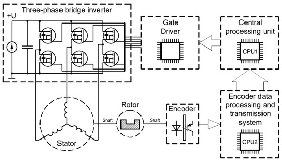
Figure 9.
Diagram of the structure of control system.
We can also note that the developed inverter scheme has a hardware-independent protection system against current overloads.
The manner of control applied to the three-phase quasi-sinusoidal system of voltages of the PMSM stator winding forms an important aspect and is hence described below.
It is commonly known that the mean value based on a rectangular period is proportional to the product
where –pulse duty factor; –its amplitude; , –period and duration of a pulse, respectively.
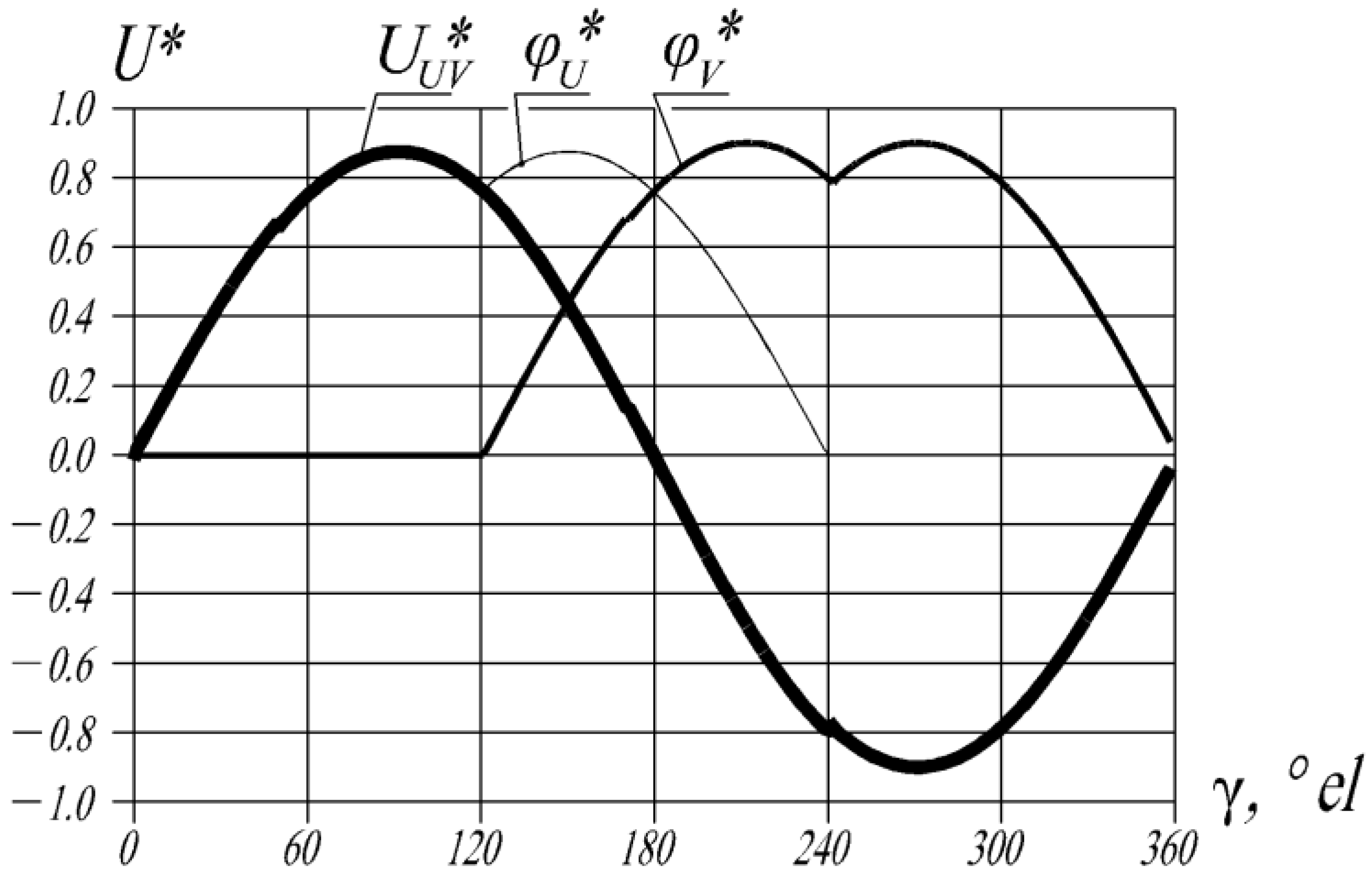
Hence, any variation in of a high-frequency signal with a constant amplitude leads to a low-frequency signal of virtually any shape. There are several approaches to shaping sinusoidal PMSM supply voltages, including variation of in accordance with the sinusoidal law. We have adopted a different approach in which the value of the duty factor varies according to a piecewise function, the appearance of which is shown in Figure 10. In such a case, the electric potential of one of the pins of the phase winding changes depending on the zero ‘earth’ potential according to the law:
where –amplitude of the potential in relative units (r.u.) (where the constant supply voltage of the bridge was taken as the basic value (); the maximum (theoretical) value ; –rotor position angle in °el.
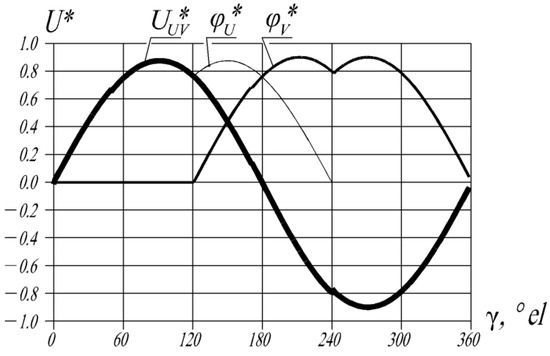
Figure 10.
The forming principle of sinusoidal supply voltages using piecewise.
The line voltage applied to the motor coils U and V is calculated as
The practical use of the inverter control algorithm requires the existence of the so-called ‘idle time’–time intervals in which both transistors in one arm of the bridge are de-energized. This leads to avoiding transient (through) currents, which are particularly important in the case of an inductive load. This significantly reduces the actual value of . For example, for a ’dead time’ of 4 μs, a 9-bit microprocessor counter running at a frequency will require a total of cycles, which corresponds to the amplitude for This value is around 12% greater than for the case of the continuous sine-like change of duty factor [26].
Figure 10, which contains the principle of forming a sinusoidal line voltage based on (24), shows that with this method of regulation, the third part of the period the ‘lower’ transistors of the bridge will be completely open and the corresponding ‘upper’ ones shut down.
6. Physical Experiments
For the PMSM engine, whose data are presented in Table 1, a number of experimental tests were carried out using the test stand described in the previous section.
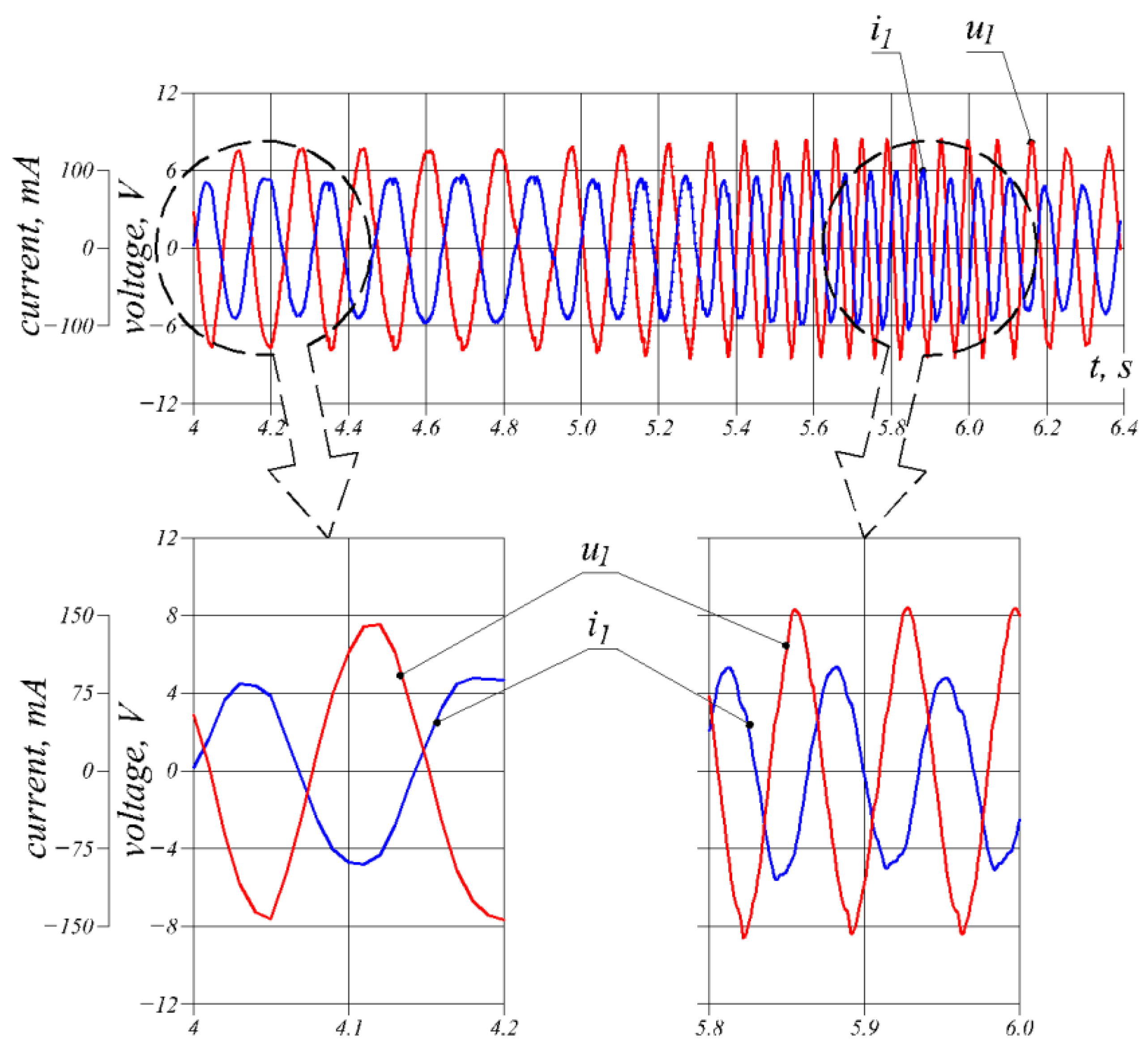
Figure 11 shows the time dependencies of the phase values of voltages and currents of the tested machine.
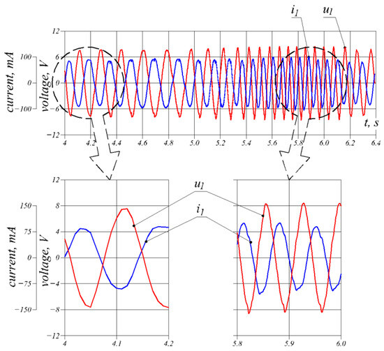
Figure 11.
Phase relationships of current and voltage with time obtained in an experimental manner.
The motor is supplied by an inverter that generates a three-phase quasi-sinusoidal voltage synchronized with the rotor position. The load on the shaft has a variable sign. The DC supply voltage was 18 V. The maximum value of the torque on the shaft, corresponding to the rotor rotation angle of 0 and , is equal to 0.234 Nm. No stabilization of rotational speed takes place in this test.
Within the range of the rotor angles ÷, the machine works in generator regime, which inevitably leads to an increase in rotational speed due to the non-compensation of the emf and the phase voltage, whose value remains constant. ON the basis of a comparison of the phase shifts between current and voltage in the motor (left) and generator (right) regimes (Figure 11), it can be seen that phase shift decreases in the generator mode. However, the value of this shift calculated theoretically was found to be greater than the one resulting from the experiment. This difference can be attributed to the presence of a relatively large friction torque in the real motor and the failure to take this torque into account in the mathematical model. As a result, the rotor speed obtained experimentally is relatively lower, and the electrical power dissipated by the machine in the generator mode on the feedback diodes of the transistors is less than the calculated values.
Phase voltage oscillations that appear twice per period can be attributed to the incomplete number of incremental encoder pulses in relation to the number of pole pairs of the motor under test. The rotation of the rotor into two polar divisions corresponds to 52 encoder pulses, which, when converted to a full revolution, is pulses. However, the encoder we use generates 1150 pulses per revolution. The difference between these values introduces an error in reproducing a sine wave signal using PWM.
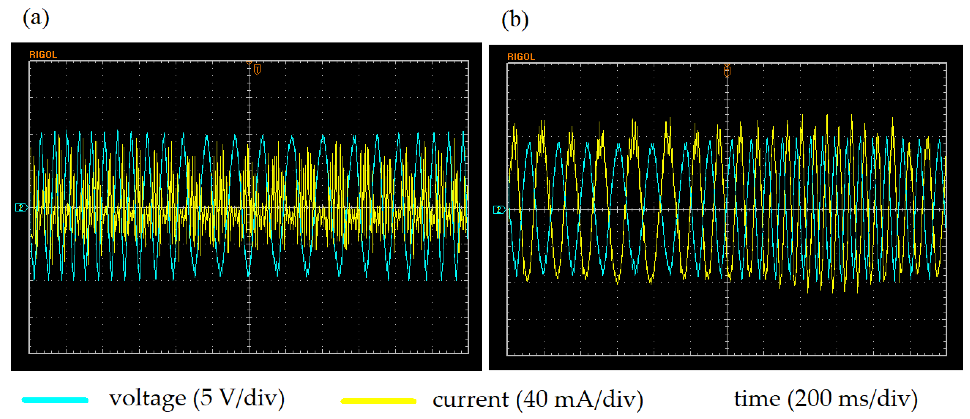
Oscillogram records of phase voltage and current for modes without speed stabilization and with speed stabilization are presented in Figure 12.
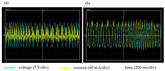
Figure 12.
Oscillogram records of phase currents, (a) excluding stabilization, (b) with stabilization.
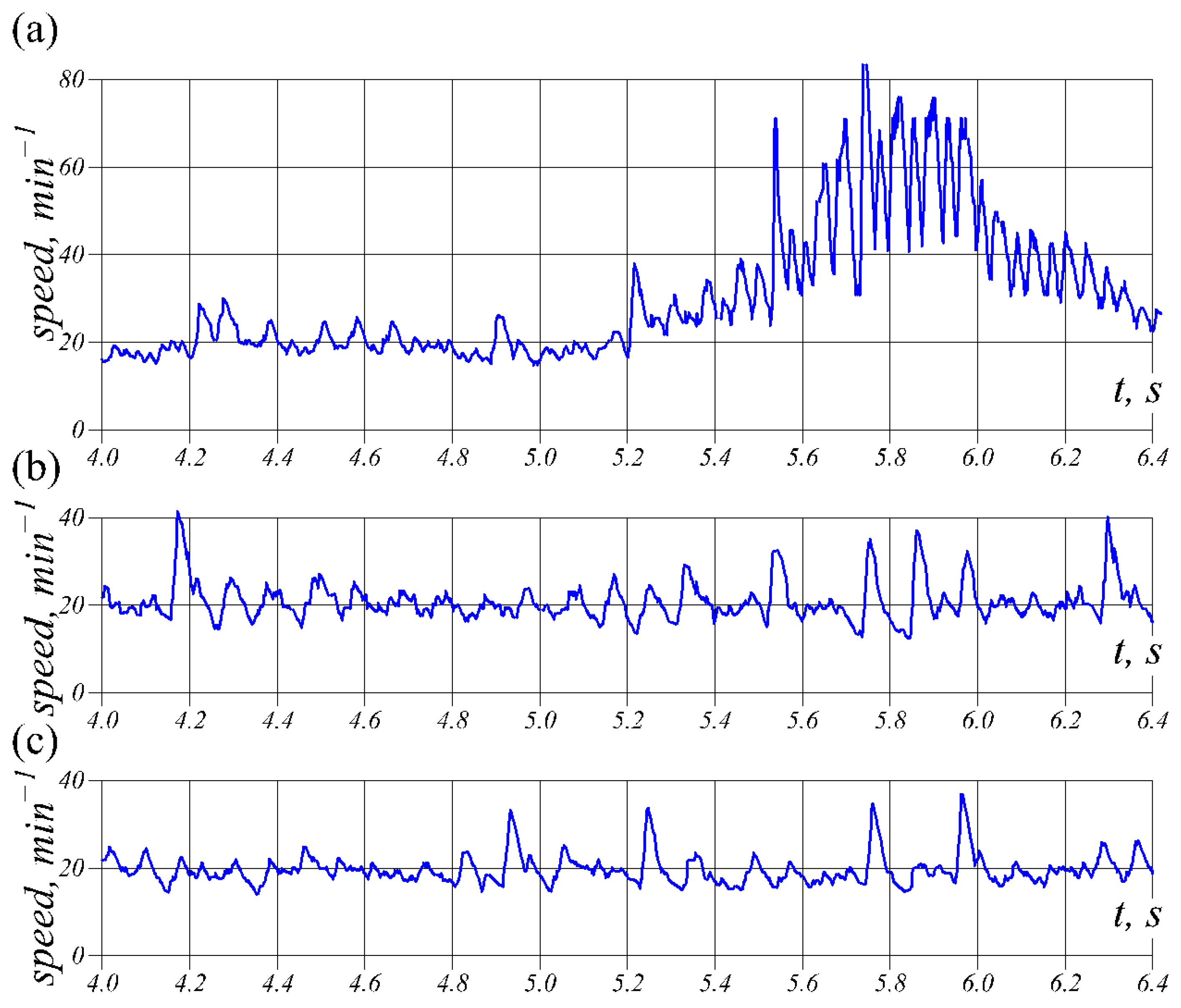
Figure 13a shows a section of the time dependence of the rotor speed of a machine operating in such a regime. For comparison, Figure 13b shows an analogous fragment, but the machine operates as a classic synchronous motor, i.e., without feedback on the angular position of the rotor and with an unchanged amplitude of phase voltages. The rotational speed pulsation in this case is rev/min.
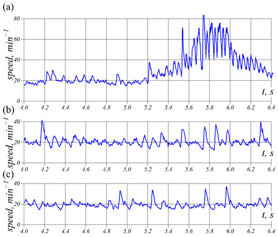
Figure 13.
Experimental dependencies of rotor speed and time: (a) with feedback on the rotor position, without rotational speed; (b) with a constant supply voltage frequency, independent of the rotor position; (c) with feedback on the rotor position and rotational speed stabilization.
The application of the proposed method of stabilizing the rotational speed, using the previously assumed laws of changing the supply voltage amplitude (9) and the load resistance value (10), made it possible to slightly reduce the rotational speed pulsation to the level rev/min (Figure 13c).
7. Conclusions
In drives that comprise PMSM motors, when the conditions provide that the load on the shaft is varied for relatively low rotational speeds, the moment of inertia of the rotating part does not contribute to its stabilization. In such cases, all the factors affecting the magnitude of pulsations become clearly visible. The proposed method of speed control ensures stabilization no lower than in the case of operation with a constant power frequency, which does not depend on the mechanical parameters of the machine.
This application of this method required neither the use of controllers nor the implementation of comprehensive vector control algorithms, which can decrease the cost of the PMSM-based drive control system as much as possible. All that is required is feedback from the rotor position and a previously assumed law of changing the load on the shaft.
This regulation method is suitable not only for cases of changing the moment on the shaft according to the expression in (8), but also for any other periodic law of moment change.
The disadvantages of the proposed method of stabilizing the rotational frequency include relatively low energy indicators as well as a decreased control accuracy. Developing the control system by adding various types of controllers will obviously improve the accuracy.
In the mathematical statement of the problem of calculating transient processes in a PMSM machine operating under a load variable sign on the shaft, the friction moment independent of the rotational speed should be taken into account (6). This will increase the level of reliability of the results obtained and comprehensively take into account the most important factors that affect the course of dynamic processes in such machines.
Author Contributions
Conceptualization, O.M. and D.C.; methodology, O.M. and D.C.; software, O.M.; validation, O.M. and D.C.; formal analysis, O.M. and D.C.; investigation, O.M. and D.C.; resources, O.M.; data curation, O.M.; writing—original draft preparation, D.C.; writing—review and editing, O.M. and D.C.; visualization, O.M.; supervision, D.C.; project administration, D.C.; funding acquisition, D.C. All authors have read and agreed to the published version of the manuscript.
Funding
This research received no external funding.
Data Availability Statement
Data are contained within the article.
Conflicts of Interest
The authors declare no conflicts of interest.
References
- Özçiflikçi, O.E.; Koç, M.; Bahçeci, S.; Emiroğlu, S. Overview of PMSM control strategies in electric vehicles: A review. Int. J. Dynam. Control 2024, 12, 2093–2107. [Google Scholar] [CrossRef]
- Liu, Y.; Song, B.; Zhou, X.; Gao, Y.; Chen, T. An Adaptive Torque Observer Based on Fuzzy Inference for Flexible Joint Application. Machines 2023, 11, 794. [Google Scholar] [CrossRef]
- Chen, C.; Luo, J.; Jin, Z. Research on Control Strategy of PMSM Driving Variable Load with Large Inertia. In Proceedings of the 2020 IEEE International Conference on Artificial Intelligence and Information Systems (ICAIIS), Dalian, China, 20–22 March 2020; pp. 514–518. [Google Scholar] [CrossRef]
- Yadav, D.; Verma, A.; Tittel, F. Permanent Magnet Synchronous Motor (PMSM) Drive Using Multi-Objective Genetic Algorithm (MOGA) Technique. In VLSI, Microwave and Wireless Technologies: Select Proceedings of ICVMWT; Springer Nature: Singapore, 2021; pp. 587–597. [Google Scholar] [CrossRef]
- Du, H.; Wen, G.; Cheng, Y.; Lu, J. Design and Implementation of Bounded Finite-Time Control Algorithm for Speed Regulation of Permanent Magnet Synchronous Motor. IEEE Trans. Ind. Electron. 2021, 68, 2417–2426. [Google Scholar] [CrossRef]
- Jung, J.-W.; Leu, V.Q.; Do, T.D.; Kim, E. -K.; Choi, H.H. Adaptive PID Speed Control Design for Permanent Magnet Synchronous Motor Drives. IEEE Trans. Power Electron. 2015, 30, 900–908. [Google Scholar] [CrossRef]
- Yao, S.; Wu, J.; Le, J. Study on Characteristic Matching and Design of Semi-Direct Drive PMSM of Beam Pumping Unit Based on Indicator Diagram. In Proceedings of the 24th International Conference on Electrical Machines and Systems (ICEMS), Gyeongju, Republic of Korea, 31 October–3 November 2021; pp. 2470–2475. [Google Scholar] [CrossRef]
- Yu, J.; Shi, P.; Yu, H.; Chen, B.; Lin, C. Approximation-Based Discrete-Time Adaptive Position Tracking Control for Interior Permanent Magnet Synchronous Motors. IEEE Trans. Cybern. 2015, 45, 1363–1371. [Google Scholar] [CrossRef] [PubMed]
- Tarczewski, T.; Skiwski, M.; Grzesiak, L.M.; Zieliński, M. Sterowanie bazujące na sprzężeniu od wektora zmiennych stanu z ograniczeniami serwonapędem z silnikiem PMSM. Przegląd Elektrotechniczny 2018, 94, 99–105. [Google Scholar] [CrossRef]
- He, R.; Han, Q. Dynamics and stability of permanent-magnet synchronous motor. Math. Probl. Eng. 2017, 9, 1–8. [Google Scholar] [CrossRef]
- Xiong, J.; Fu, X. Extended Two-State Observer-Based Speed Control for PMSM With Uncertainties of Control Input Gain and Lumped Disturbance. IEEE Trans. Ind. Electron. 2024, 71, 6172–6182. [Google Scholar] [CrossRef]
- Kim, D.-J.; Kim, B. Linear Matrix Inequality-Based Robust Model Predictive Speed Control for a Permanent Magnetic Synchronous Motor with a Disturbance Observer. Energies 2024, 17, 869. [Google Scholar] [CrossRef]
- Junejo, A.K.; Xu, W.; Mu, C.; Ismail, M.M.; Liu, Y. Adaptive Speed Control of PMSM Drive System Based a New Sliding-Mode Reaching Law. IEEE Trans. Power Electron. 2020, 35, 12110–12121. [Google Scholar] [CrossRef]
- Liu, W.; Luo, B.; Yang, Y.; Niu, H.; Zhang, X.; Zhou, Y.; Zeng, C. An Adaptive-Gain Sliding Mode Observer with Precise Compensation for Sensorless Control of PMSM. Energies 2023, 16, 7968. [Google Scholar] [CrossRef]
- Durdu, A.; Dursun, E.H. Sliding Mode Control for Position Tracking of Servo System with a Variable Loaded DC Motor. Elektron. Ir Elektrotechnika 2019, 25, 8–16. [Google Scholar] [CrossRef]
- Datlinger, C.; Hirz, M. Benchmark of rotor position sensor technologies for application in automotive electric drive trains. Electronics 2020, 9, 1063. [Google Scholar] [CrossRef]
- Bibik, O.V.; Mazurenko, L.I.; Shykhnenko, M.O. Formation of characteristics of operating modes of switched reluctance motors with periodic load. Electr. Electromech. Eng. 2019, 4, 12–16. [Google Scholar] [CrossRef]
- Lu, L.; Mao, Y.; Wang, X.; Jin, L.; Wang, Z. Maximum-Torque Optimization Control of Dual Three-Phase PMSM in Low-Frequency and Static Operations. IEEE J. Emerg. Sel. Top. Power Electron. 2023, 11, 5268–5278. [Google Scholar] [CrossRef]
- Makarchuk, O.; Kharchyshyn, B.; Kasha, L. Analysis of the Magneto-Mechanical Characteristic of Double Three-phase PMSM. In Proceedings of the 3rd Ukraine Conference on Electrical and Computer Engineering (IEEE UKRCON-2021), Lviv, Ukraine, 26–28 August 2021; pp. 333–338. [Google Scholar] [CrossRef]
- Teymoori, V.; Kamper, M.; Wang, R.-J.; Kennel, R. Sensorless Control of Dual Three-Phase Permanent Magnet Synchronous Machines—A Review. Energies 2023, 16, 1326. [Google Scholar] [CrossRef]
- Popenda, A. A concept of control of PMSM angular velocity. Przegląd Elektrotechniczny 2013, 89, 290–292. [Google Scholar]
- Sim, H.W.; Lee, J.S.; Lee, K.B. On-line parameter estimation of interior permanent magnet synchronous motor using an extended Kalman filter. J. Electr. Eng. Technol. 2014, 9, 600–608. [Google Scholar] [CrossRef]
- Do, T.D.; Kwak, S.; Choi, H.H.; Jung, J.-W. Suboptimal Control Scheme Design for Interior Permanent-Magnet Synchronous Motors: An SDRE-Based Approach. IEEE Trans. Power Electron. 2014, 29, 3020–3031. [Google Scholar] [CrossRef]
- Skowron, M.; Orlowska-Kowalska, T.; Kowalski, C.T. Diagnosis of Stator Winding and Permanent Magnet Faults of PMSM Drive Using Shallow Neural Networks. Electronics 2023, 12, 1068. [Google Scholar] [CrossRef]
- Ruiz, J.R.R.; Espinosa, A.G.; Romeral, L.; Cusido, J. Demagnetization diagnosis in permanent magnet synchronous motors under non-stationary speed conditions. Electr. Power Syst. Res. 2010, 80, 1277–1285. [Google Scholar] [CrossRef]
- Makarchuk, O.V.; Khai, M.V. Structure and control algorithm of a low-speed servo drive based on a synchronous motor with permanent magnet excitation. In Bulletin of the National Technical University “KhPI”: A Collection of Scientific Papers: NTU “KHPI”; Khai, M.V., Ed.; National Technical University “KhPI”: Kharkiv, Ukraine, 2017; 1(1223); pp. 28–34. [Google Scholar]


Disclaimer/Publisher’s Note: The statements, opinions and data contained in all publications are solely those of the individual author(s) and contributor(s) and not of MDPI and/or the editor(s). MDPI and/or the editor(s) disclaim responsibility for any injury to people or property resulting from any ideas, methods, instructions or products referred to in the content. |
© 2024 by the authors. Licensee MDPI, Basel, Switzerland. This article is an open access article distributed under the terms and conditions of the Creative Commons Attribution (CC BY) license (https://creativecommons.org/licenses/by/4.0/).