Review

Graphitic Carbon Nitride (g-C3N4) in Photocatalytic Hydrogen Production: Critical Overview and Recent Advances

by
Periklis Kyriakos
,
Evangelos Hristoforou
* and
George V. Belessiotis
*
School of Electrical and Computer Engineering, National Technical University of Athens, Zografou, 15780 Athens, Greece
*
Authors to whom correspondence should be addressed.
Energies 2024, 17(13), 3159; https://doi.org/10.3390/en17133159
Submission received: 25 May 2024 / Revised: 21 June 2024 / Accepted: 25 June 2024 / Published: 27 June 2024

Abstract

:
Graphitic carbon Nitride (g-C3N4) is one of the most utilized graphitic materials in hydrogen (H2) production via photocatalytic water splitting. Thus, a detailed critical overview, updated with the most recent works, has been performed on the synthesis methods, modification techniques, characterization, and mechanisms of g-C3N4 and g-C3N4-based composite materials, with the aim of clarifying the optimum course towards highly efficient hydrogen-producing photocatalysts based on this promising material. First, the synthesis methods for different morphologies of pure g-C3N4 (bulk, nanosheets, nanotubes and nanodots) are critically analyzed in detail for every step and parameter involved, with special mention regarding the modification methods of g-C3N4 (doping and composite formation). Next, the most common results of g-C3N4 characterization, regarding structural, morphological, optical, and electrical properties, are presented and analyzed. Then, a detailed critical survey of the mechanisms, using g-C3N4 and g-C3N4-based composites during photocatalytic activity, is performed with a focus on their effect on their hydrogen production capabilities via water splitting. This review aims to provide a clear image of all aspects regarding the use of g-C3N4 for photocatalysis, as well as a comprehensive guide for research targeted towards this promising graphitic material.

Graphical Abstract

1. Introduction

As a result of accelerated industrialization and the use of fossil fuels [1,2], each year, massive amounts of greenhouse gases such as CO2, SOx, and NOx are released into the earth’s atmosphere, with the increasing degradation of the natural environment presenting many dangers to human health [3,4] and significant harm to natural ecosystems. Furthermore, the limited availability of such fuels is a major problem [5], with several approaches being applied in the field of energy, such as storage or the use of renewable energy sources [6,7,8]. Hydrogen energy as a promising clean alternative has the potential to contribute to a sustainable carbon-neutral future [9] due to its high energy density [10]. Although there are many methods for hydrogen (H2) production, with the most common being electrolysis [11,12,13], there has been a surge in research regarding the technique of photocatalysis. Photocatalysis is an environmentally friendly method that requires only natural sunlight for its operation and can be utilized for a variety of applications from water decontamination to water splitting [14,15,16,17]. The general process of photocatalysis involves the irradiated generation of charged pairs: After the irradiation of a semiconductor via a light source with photon energy above the material’s band gap, the electrons in the valence band (VB) are excited and transferred to its conduction band (CB). This creates an electron/hole pair in the respective VB/CB of the material, which can then be used for catalytic reactions (reduction/oxidation of molecules). The basic qualities required of a proper photocatalyst are good light response and efficient charge generation, separation, and transfer capabilities, along with stability, energy level positions, and high specific area. It is desirable for a photocatalyst to be able to absorb low-energy photons (from the visible light spectrum), in addition to high-energy UV light, as a great percentage of natural sunlight belongs in this wavelength range. Furthermore, it is necessary to have good charge separation characteristics as one of the most common issues in photocatalysis is recombination. The tendency of photogenerated electrons to combine with holes in the VB impairs the material’s function as there are fewer species available to participate in the desired photocatalytic reactions. Finally, the positions of the material’s energy levels define its ability to perform the necessary redox reactions.
One of the more common graphitic materials used in such photocatalytic applications is graphitic carbon nitride (g-C3N4) [18,19,20,21,22,23]. g-C3N4 has sparked growing interest in recent years due to its potential applications in various fields, including hydrogen production, pollutant degradation, carbon dioxide conversion, electrode construction, antibacterial activity, and sensor development [24,25]. The increasing interest in graphitic carbon nitride (g-C3N4) for photocatalysis applications stems from its unique properties due to its graphite-like structure and nitrogen-rich sites, making it an excellent base material for the synthesis of binary and ternary composite catalysts. It has been extensively utilized in the field of water splitting in the past few years due to its easily obtainable precursors, simple synthesis method, suitable band gap energy of 2.7 eV [26], non-toxicity, chemical and thermal stability as well as chemical inertness in most environments [27,28,29]. It has a multi-layered structure that is held together by stable van der Waals forces that can be loosened at temperatures above 450 °C, with each layer being characterized as aromatic heterocyclic [30]. Two district structures have been identified as the building blocks of g-C3N4, i.e., heptazine and triazine (Figure 1), with the former suggested to be the most stable [31]. Electron pairs of sp2 hybridized carbon and nitrogen atoms form a delocalized π-conjugated network that is believed to be the source of the photocatalytic reactivity of g-C3N4 [31,32].
The importance of a good visible light absorption capability is known in the photocatalytic field [33,34,35]; as such, photocatalysts can take better advantage of natural sunlight. g-C3N4 has a good visible light response compared to common photocatalysts (such as TiO2 or ZnO), which are reactive only under UV light [36,37,38,39]. Moreover, g-C3N4 conduction and valence band potentials are well-suited for hydrogen production through water splitting [26]. Despite its positive aspects, graphitic carbon nitride (CN) suffers from certain drawbacks that hinder its widespread usage as an effective photocatalyst. Some of the negative properties of pure CN, as reported by a great number of works, are rapid electron–hole recombination [40], limited-time excitation span, lower carrier mobility, decreased visible light permeability, and low specific surface area in the bulk form [41]. Research into CN is currently focused on developing new methods and composite materials to surpass these issues as it remains one of the best base components for synthesis that can be tuned to effectively function in photocatalytic systems.
Several methods have been proposed to overcome the shortcomings of CN, such as structural modification, (non-metal) doping, heterojunction formation, and co-catalyst addition. Structural modification targeted towards the enhancement of g-C3N4 as a base photocatalytic material can be achieved through various routes, the most popular being morphology alteration [42], doping [43], composite heterojunction formation [30,44,45] and co-catalyst decoration [40]. g-C3N4 particles have the capacity to undergo further structural alteration processes [46], which results in the formation of nanoparticles that closely resemble nanosheets [32], nanotubes [47], nanodots [48], and various other more complex structures [49] that are not defined precisely. The shift from bulk to sheets/tubes greatly increases the specific area of the material (and thus the number of active sites for photocatalysis). This effect is augmented in nanodots. Furthermore, visible light absorption is enhanced in micropore-containing structures (e.g., flakes created by sheets or tubes). These increases positively affect photocatalytic performance. The introduction of these novel particles leads to a notable enhancement in their photocatalytic properties in comparison to the previous form of g-C3N4. Moreover, these advanced particles play a crucial role in significantly boosting the efficiency of hydrogen production when integrated into composite catalyst systems [50]. For example, 1D nanotubes allow electron migration throughout their length, limiting their movement in all other possible directions due to quantum confinement [51]. Regarding non-metal doping, it includes co-polymerization methods [31] with N-rich substances to enhance the presence of amino groups on the surface of the catalyst [52], the addition of more carbon atoms to change the C/N ratio [53], or the integration of other non-metal atoms (e.g., P, S, Se, and others) as defects in the g-C3N4 lattice [53]. The introduction of amino groups can result in more thermodynamically favorable interactions with water, improving the solubility of photocatalytic materials in aquatic solutions [52].
A different approach to tackle these issues is forming a heterojunction between two semiconductors. Carbonaceous graphite-like material such as g-C3N4, in combination with transitional metal oxides (e.g., TiO2 [18], WO3 [27], or CuBi2O4 [54]) or sulfides (e.g., CdS or CuInS2 [36,55]) can function as such. Heterojunction formation assists the charge carrier separation and electron transfer rate at the interface through the modification of the localized electric field and bending of electron bands on site. Various types of heterojunctions have been reported in photocatalysis, including type-II, Direct Z-scheme, and Direct S-Scheme, with one material functioning as the oxidizer and the other as a reducing agent. Although g-C3N4 materials are commonly utilized as a foundational substrate for the purpose of introducing foreign particles, instances of the opposite scenario where g-C3N4 is used as a co-catalyst have also been documented [43].
Finally, with the use of noble metals such as Pt, Ag, Pd and Au in place of a co-catalyst [14], synthesized photocatalysts can increase the number of active sites due to the LSPR (Localized Surface Plasmonic Resonance) effect, reinforcing light absorption and, in turn, yielding better water splitting results [56]. More specifically, metal deposition/doping of g-C3N4 has been proven to increase surface area, narrow the band gap, align band structure for optimal light absorption, and lead to higher rates of charge carrier transfer [41]. Metallic co-catalysts find themselves in the final material either by pre-integration during synthesis [57] or by in situ photo-deposition during photocatalytic testing [28]. It is important to note that recent studies have investigated the possibility of replacing scarce noble metals with structures produced solely from graphitic compoundsas co-catalysts [58]. There have been reports of g-C3N4 acting both as a base catalyst and a co-catalyst, for example, g-C3N4 sheets decorated with g-C3N4 nanodots [59]. Surface-loaded nanodots act as a co-catalyst, improving their visible light absorption and increasing the number of active sites. This strategy, in addition to being low-cost, is also eco-friendly. Despite the omission of noble metals, composite materials employing graphitic materials as co-catalysts can have remarkably high hydrogen production efficiency [27].
In this work, the most recent advances in g-C3N4 synthesis, characterization, modification, and application in photocatalytic water splitting are critically reviewed. A detailed look into the different synthesis techniques of pure and modified g-C3N4 for each of its most well-known morphologies is followed by a complete characterization map based on reported g-C3N4 property analyses of past works. Finally, the mechanisms that allow g-C3N4’s function in photocatalytic materials are studied, and their effects on H2 production via water splitting are presented. The scope of this work is the accumulation of the current knowledge, refined by a critical view, which will allow a better understanding of the potential techniques to increase the effectiveness of this very promising material in photocatalysis.

2. Synthesis Methods

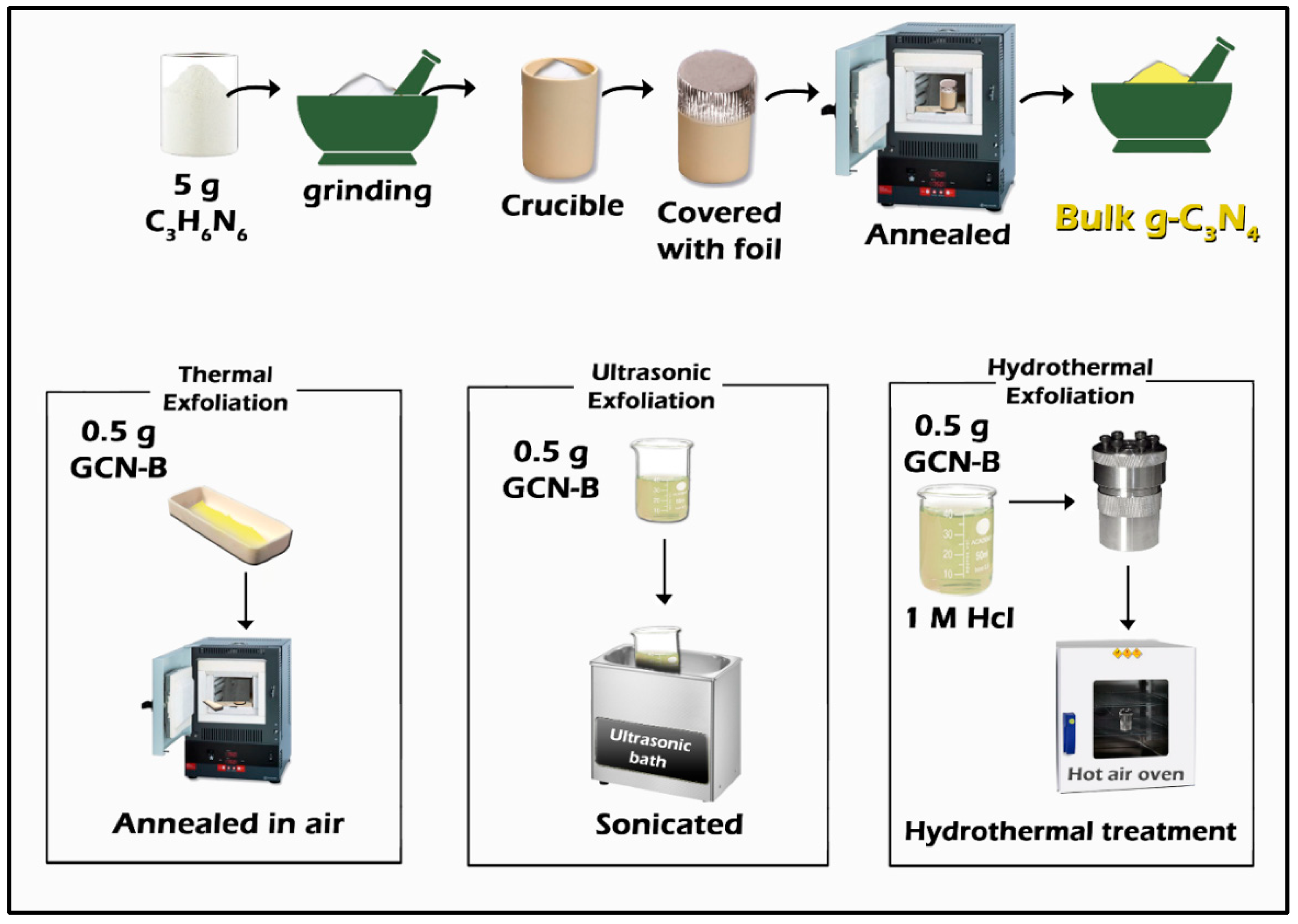
2.1. Bulk g-C3N4 Synthesis

g-C3N4 is mainly prepared through the use of nitrogen-rich precursors, including melamine [27,41,52,60,61], dicyanamide (C2H4N4) [57], cyanamide [40], urea [28], thiourea (for direct S-doped g-C3N4) [40], and cyanuric acid [59,62]. Some recently employed methods are summarized in Table 1.
Melamine is most commonly used [32] in graphitic photocatalyst synthesis and has the closest relation to the monomer molecule that condensates to produce g-C3N4 sheets. Urea, also commonly used [36,40,46], is a low-cost and easily obtainable precursor [36,46]. Urea is also converted into melamine through polymerization at 250–300 °C. As shown in Figure 2, some reported precursors correspond to different chemical species produced during the complex polymerization reaction needed to produce g-C3N4 [40]. Urea breaks and produces dicyanamide units, which further react to form melamine at around 250–350 °C. In the following step, individual melamine units react, forming melam and melem units [40]. Melamine poly-condensates into melam and melem above 210 °C [62]. In the 500–550 °C range, the majority of individual units of melam polymerize, forming stacked nanosheets particles [32]. In particular, samples prepared at 550 °C display a highly crystalline periodic heptazine structure [40]. The bulk form of g-C3N4 is mainly referred to as the stacked lamellae structure, although its morphology may be more complex in practice [26], containing sheets and tubes as well. It is suggested that -NH and -OH groups at the edges of sheets react to form stacked-layer aggregates [63].
The pyrolysis method [52], also referred to as calcination [46], describes the process of heating precursors such as melamine [27] to initiate the polymerization reaction forming melam monomers, which connect to form the tri-s-triazine (heptazine) structure. Heptazine structures further condense, producing individual layers, stacked on top of each other. Pre-grinding of melamine and urea prior to the application of heat has been documented [27,36,40].
Three key parameters consistently reported during pyrolytic treatment are treatment temperature, reaction time, and heating rate [36,46]. Most bulk CN synthesis methods in photocatalysis research employ a calcination process involving heat treatment of the precursor material at temperatures ranging from 500 °C [41] to 650 °C [60] inside a ceramic crucible (with or without [27] cover) [27,36,52] wrapped in aluminum foil [40]. Most studies report treatment in atmospheric air [52], although inert gas atmospheres such as N2 or Ar [60] have also been used.
In the case of urea as a precursor, the fabrication of bulk g-C3N4 is carried out by heating at temperatures around 550 °C. Urea undergoes decomposition and polymerization to form stacked CN sheets in a complex reaction [46]. Heating time is reported with the greatest degree of variation, ranging from 2 h [32,48] to 4 h [36] and 5 h [52], with 4 h being the most common length of time employed [64]. Prolonged heating durations promote extended polymerization reactions, leading to an increased specific surface area and enhanced crystallinity of the resulting CN material [46].
The rate of temperature rise plays a pivotal role in the creation of all-graphitic nitride forms. A heating rate of 15 °C/min is considered rapid, while 5 °C/min is the slowest rate reported in recent works, with 10 °C/min being in the middle [36]. While it would be logical to presume that ramp rates of 5 °C/min [52] or lower [60] (e.g., 2.5 °C/min [27]) would be ideal to ensure homogenous heat transfer and that polymerization takes place through the material, resulting in a finely formed crystal, this is not the case. As detailed by a recent study [46], high heating rates provide insufficient amounts of energy, and urea pyrolysis is inhibited. At higher sample temperatures, the required heat for pyrolysis to take place is supplied, and all intermediates react simultaneously. The release of NH3 gas through the reaction provokes pore formation and supplies a nitrogen-rich atmosphere, enriching the g-C3N4 structure with amino groups. In contrast, low heating rates have been correlated to increased crystallinity [61].
Elevated calcination temperatures, high heating rates, and extended reaction times are advantageous for synthesizing g-C3N4 with enhanced crystallinity, reduced layer thickness, and increased interlayer spacing. This optimized morphology is more suited for photocatalytic activity due to the promotion of efficient charge carrier transport within the material [46].
Reported products’ colors range from bright to pale yellow [27,36,41,52,60,61]. Bulk form g-C3N4 is expected to have a yellow color [65]. In retrospect, the crystallinity, structure, and color of g-C3N4 seem to be correlated, consistent with reported findings [36,46], showing a rate increase, leading to a fading of the yellow color.
High temperatures, e.g., those exceeding 550 °C, usually combined with treatment times surpassing 4 h, have been linked to the development of highly crystallized g-C3N4 substances, which can showcase a distinct pale yellow color. The same color has been achieved in another study [48] while using a shorter treatment time (2 h). In contrast, lower temperatures, with short heating times, at which the formation of g-C3N4 is not fully realized, could lead to the production of materials displaying a bright yellow color, suggesting differences in structure and composition.
Yang et al. reported that temperatures lower than 580 °C with short heating times and slow heating rates exhibit decreasing photocatalytic efficiency [46].
Following the previous steps, calcinated powders are subjected to washing with solvents (commonly DI water and methanol), centrifugation, and drying for extended periods of time [52,60]. Often, post-calcination grinding is employed again to avoid agglomeration [52,61].
The synthesis methods can be divided into two categories according to the number of steps: indirect synthesis methods, followed by a step-by-step succession of processes, during which every constituent of the final catalyst is realized. Direct synthesis methods, also called “one-step”, differ from indirect methods by aiming to produce the final material in a single step. However, the distinction between the two can be difficult because the formation of bulk CN, which is mostly encountered in the introductory step of indirect methods, is also included in direct methods even though it is not specifically stated.
Table 1. Various g-C3N4 calcination precursors, parameters, and product properties.
PrecursorTemperature (°C)Heating Time (h)Ramp Rate (°C/min)ColorStructureRef.
Melamine55032.5Lemon chiffon [27]
Melamine400, 5501, 23Pale yellow-[61]
Melamine5004-YellowishBulk[41]
Melamine55025YellowBulk[32,52]
Melamine65022YellowBulk[60]
Urea520410Pale yellowBulk[36]
Melamine60025Pale yellow-[48]
Urea and dicyandiamide5504--Bulk[66]
Melamine55051Bright yellow [67]
Melamine55042-Flakes[40]
Urea5504 -Flakes[40]
Melamine55015Light yellowBulk[67]
Melamine60025YellowBulk[42]
Urea55031-Semi-stacked sheets[26]
Melamine520410-Bulk[65]
Dicyandiamide60022Pale yellowBulk[68]

2.2. g-C3N4 Nanosheet Synthesis

The term “nanosheets”, specifically for g-C3N4, refers to the 2D formation created by chains of tri-s-triazine-ring building blocks connected via hydrogen bonds, which are located on the bridging imide groups. In many recent works, the formation of nanosheets is the next step after the formation of bulk g-C3N4 [57]. The transitional process of bulk-material stacked-layer delamination, in order to create single planar formations (sheets), is known as exfoliation, also referred to as annealing [41]. The detachment of layers needs enough energy to overcome van Der Waals forces present due to π–π stacking [69].
The reason for the popularity of 2D nanosheets in this research field is that deriving composites display improved photocatalytic characteristics over their bulk counterparts, such as increased specific surface area and improved charge carrier separation and mobility [57]. Nanosheet morphology is commonly encountered as the CN sub-structure supporting metal and semiconductor dopants or co-catalysts [32,43]. Despite this common ground in photocatalytic research, there are examples of using other materials to create similar nanoscale formations along with conventional g-C3N4 sheets. Complex systems of multi-compositional nanosheets integrated with each other have been achieved, with great improvement in photocatalytic characteristics (e.g., WO3 nanosheets on C3N4 nanosheets) [27]. Embodied N atoms in g-C3N4 sheets are suggested to have a pivotal role in achieving homogenous decoration with secondary-phase nanocomponents [57]. More than one method of exfoliation has been proposed, with three of them appearing in most research works (Figure 3) in the following order of efficacy: thermal [59], hydrothermal [66] and ultrasonic [27]. These methods are analyzed below.

Exfoliation Methods

Thermal exfoliation or re-calcination is the simplest method of CN exfoliation, involving fewer steps compared to the other two methods discussed in this section (Table 2). Bulk CN powder is thoroughly ground in a mortar until a fine particle size is achieved. Finely ground powder is spread in a thin layer across the surface of a ceramic vessel to maximize homogenous heat application. Prepared samples are treated at temperatures close to the initial calcination temperature (around 550 °C) for bulk CN production [27,42,66]. In a special case, initial calcination temperatures of 400 °C have been used to treat melamine, followed by a second phase at 550 °C, with 2h calcination at 3 °C/min. Despite the low initial calcination temperature, the sample resulted in 2D sheet morphology, indicating the effectiveness of re-calcination [61]. This could be explained by the previously detailed g-C3N4 reaction [46]. Thermal exfoliation is executed similarly to the initial step that produces bulk g-C3N4 (2 h treatment at 520 °C has been reported [27,66]). After exfoliation, the samples exhibit a white color with a slight yellowish tint [27,61]. Slower heating rates have been proven to result in flake-like structures formed by sheets [46]. Surrounding atmospheric conditions are significant in exfoliation. Exfoliation in air and CO2 atmospheres has been shown to produce sheets with pale yellow and yellow ochre color, respectively [42]. Re-calcination at higher temperatures, such as 750 °C, despite producing well-shaped nanosheets, is not favorable for photocatalytic results [68].
The hydrothermal–chemical treatment, mainly used as a means to integrate metal and semiconducting nanoparticles in graphene structures, can also function as an exfoliation method [66]. A main drawback of this process is the need for an extra precursor-acidic solution and special equipment (Teflon-lined autoclave) compared to thermal exfoliation. As reported by Bharagav et al. [27], a portion of CN powder was dispersed into an acidic solution (HCl) with continuous stirring for an hour. Further, the solution was inserted into an autoclave and heated for a period of 5 h at 120 °C. The solution was left to cool down to ambient temperature, thoroughly washed with DI water (repeated several times to remove the remaining acid), and finally dried to receive the exfoliated nanosheet powder.
Ultrasonic exfoliation is generally carried out by sequentially dissolving small portions of prefabricated bulk g-C3N4, employing ultrasonication and centrifugal separation cycles. DI water is a suitable candidate for dissolution due to its adequate polarity and cost-effectiveness [27]. Alcohols are also suitable solvents, with ethanol effectively being used in the production of thin-layer morphology in CN nanosheets [41]. The graphitic material and solute separation are achieved through concurrent high-speed (8000–12,500 rpm) centrifugation cycles and washing. Finally, to obtain the pale yellow solid-powder nanosheets, the process is finalized by drying [27]. Another study has documented the successful emergence of nanosheet morphology by employing gentle temperature ramp rates of 3 °C/min [60].
Other more direct synthesis approaches have been reported, for example, the employment of a mechanochemical process, comprising of a combination of grinding the powder precursor (dicyandiamide), followed by calcination at temperatures as high as 720 °C in an N2 gas environment [57]. A similar method was used by another work [59]. Melamine and cyanuric acid powders were mixed and milled (mechanical treatment) and then calcinated at 520 °C for 4 h at a rate of 20 °C/min. Formed sheets exhibited a clear sheet morphology, indicating that milling pre-calcination may play a pivotal role as calcination conditions were different from the previous mechanochemical methodology. A combination of two precursors has also been used by Wang et al. [70], who directly synthesized S-doped g-C3N4 nanosheets by thiourea/urea mixture calcination.

2.3. g-C3N4 Nanotube Synthesis

Carbon nanotubes (CNTs) are one-dimensional formations of CN, created by curling-crimping nanosheets to produce various tube-like architectures, such as single-layer hollow tubes, multiple-layer tubes, solid rods, and horn-like structures [28,60]. Compared to 2D and 3D morphologies, CNTs are more efficient at improving photocatalytic performance [72].
Iqbal et al. attempted an indirect synthesis of nanotubes from prefabricated CN nanosheet powder involving a heating treatment close to 300 °C (10 °C/min rate). After the immediate transfer to an ice-water bath, the resulting nanotube powder was collected by filtration and vacuum drying [41]. The direct synthesis of nanotubes needs the addition of an extra precursor, in addition to melamine. Nanotubes have been prepared by calcinating solid mixtures of urea–melamine and urea–cyanuric acid (calcinated at 550 °C for 4 h at 5 °C/min) [62]. A urea–melamine combination was also used by Tahir et al. for the same purpose, using the same temperature but a different heating duration, i.e., 2 h [73]. A mix of urea and thiourea has also been reported as possible precursors for nanotubes, produced by pre-calcination at 350 °C, followed by the main calcination process being carried out at 600 °C for a duration of 3 h [10]. The heating rate also affects the curling process, with medium rates of 1.7–2 °C/min giving the best results for tube formation. This is due to lower rates increasing CN sheet crystallinity, leading to a drop in surface energy. Increased crystallinity and lower surface energy mean that sheet formations are highly stable and that the curling process is unlikely to be initiated [60].
Stages of morphological transitions to a 1:10 mixture of urea at 550 °C for a very short calcination time of 5 min were described in detail by another study [47]. Notably, (a) solid rods were formed when the temperature reached 350 °C, (b) a hollow nanotube structure was gradually produced when the temperature exceeded 400 °C, and finally, symmetrical g-C3N4 nanotubes were obtained at 550 °C. In contrast to [10], calcination at temperatures near 600 °C resulted in tubular structure collapse.
Yang et al. [74] synthesized thin wall nanotubes via a three-step process using melamine, which involved (a) a first calcination step (550 °C, 4 h, and 5 °C/min) for bulk morphology, (b) hydrothermal treatment with the addition of cyanuric acid to create hexagonal columnar crystals, (c) re-calcination (500 °C, 2 h, and 5 °C/min) in similar conditions to obtain tubes, and finally, calcination under 70 °C in an argon gas atmosphere to form hollow tubes.

2.4. g-C3N4 Nanodot Synthesis

Graphitic carbon nitride quantum dots (CNQDs) refer to nanoscale spherical formations with an average diameter of less than 10 nm. Owing to their small size, such nanoparticles have a larger specific surface area than other structures of g-C3N4 reported herein, thus exhibiting a plethora of catalytically active sites. A quantum size effect, also apparent in sheet and tube architectures, is very pronounced in QDs, with researchers characterizing them as 0D materials. Due to the quantum confinement effect, these materials can efficiently utilize light [28].
Graphitic carbon nitride quantum dots (g-C3N4 QDs) have undergone thorough investigation owing to their remarkably high quantum yield, presence of enriched catalytic sites as well as the distinctive quantum confinement and edge effects that they exhibit, all of which have proven to be advantageous in photocatalysis [75]. Moreover, CNQDs can reduce interface defects during the semiconductor composite formation, thus increasing charge carrier transportation between the two components [28].
In all cases (Table 3), typical calcination treatment precedes nanodot formation in order to produce the bulky layered sheet structure first, e.g., 550 °C for 4 h. The production of nanodots has been found to arise from both urea [29] and melamine [48]. g-C3N4 nanodot synthesis methods can be broken down into four steps: (a) the thorough dispersion into a concentrated acid solution (e.g., HNO3 or HCl) with heating (e.g., around 80 °C) [48], which is carried out through shaking for extensive periods (up to 24 h), with the resulting solution slowly added into a DI solution [28]; (b) the centrifugation of solid particles, repeatedly washed until their pH is neutralized [28,29]; (c) solvothermal treatment in a PTFE-lined vessel (e.g., at 180 °C–200 °C for nearly 10 h) [29,48]; and (d) water-particle separation, executed by freeze-drying, avoiding evaporation [28,48].
Some notable variation in the methodologies includes the replacement of heat treatment with ultrasonication for a long period (e.g., 20 h) and 22 μm Millipore membrane filtration by a recent work [28]. In another study [48], after solvothermal treatment, the sample was subjected to filtration before drying. In comparison, inorganic QD synthesis such as CuInS2, despite following a similar solvothermal method, differs greatly in procedural conditions, such as a basic pH, short treatment time (e.g., 60 min), and lower calcination temperature (e.g., 90 °C) [36].

2.5. Doping and Composite Synthesis

A significant challenge regarding g-C3N4 synthesis and modification is the achievement of high photocatalytic efficiency without the use of additional materials (i.e., composites). Further study is needed concerning its synthesis protocols, morphology, and doping techniques in order to render the basic g-C3N4 truly efficient in photocatalysis. Non-metal doping of the g-C3N4 lattice is an effective method for constructing nanotubes [51,53]. CNT structure can also be accomplished by the re-crystallization of pure melamine in a water solution and thermal polycondensation for the direct synthesis of tubular structures without the prefabrication of sheets. In that case [72], transitional metal salts are required during the re-crystallization process, with FeCl3, MnCl2, and NiCl2 resulting in metal-doped tubular morphology at temperatures of 650 to 750 °C.
The direct insertion of non-metal dopants into CN for a nanotube structure has been achieved at higher temperatures (close to 650 °C) in an inert Ar atmosphere using melamine and dibenzyl sulfide as precursors. As reported in [60], the calcination temperature has a profound impact on the nanostructure formation mechanism, with temperatures of 650–700 °C being considered the optimum range for tubular morphology. The reaction mechanism was thoroughly researched by Liu et al., leading to the following conclusions: (a) uneven ratios of P and S result in non-symmetrical folding of nanosheets, producing horn-like structures, (b) even ratios of P and S produce nanotubes, and (c) the concentrations of P and S determine the density of the nanotube structure, with lower concentrations (0.25–1 wt%) leading to single-layer nanotubes and higher concentrations of 2% and 4% leading to tube-in-tube and solid nanorod structures, respectively. Treatment temperatures above 750 °C have a negative impact as they lead to the structural disintegration of CN.
Co-doping produces interesting results regarding the formation of various nanotube structures. The incorporation of inorganic atoms of sulfur (S) and phosphorus (P) in various ratios has a synergistic effect that results in variation in the synthesized structure [10]. The integration of P and S has a double effect on the g-C3N4 structure, with P substituting carbon and nitrogen atoms in CN sheets due to its higher electro positivity and S atoms acting as a linking agent between curling sheets, accentuating tube formation [60]. Nitrogen is another option used to enhance the N/C ratio in a g-C3N4 structural unit. “Self” N-doped nanotubes have also been created via a two-step process, with the first step being hydrothermal treatment (e.g., 180 °C for 12 h) and the second being calcination (e.g., at 550 °C for 4 h) [51]. Wang et al. directly synthesized s-doped g-C3N4 nanosheets by thiourea/urea mixture calcination [70].
The wet impregnation method, which shares many similarities with the aforementioned hydrothermal method, is a frequent choice for creating metal oxide–carbon nitride composites. For example, in one case, CuO/g-C3N4 has been obtained by dissolving both precursors (copper nitrate hexahydrate, i.e., Cu(NO3)3·6H2O, for CuO) into DI water. Then, solution mixing and heat treatment occur at 300 °C for 2 h at 2.5 °C/min, followed by grinding. The resulting product is a bulky graphene structure with uneven CuO nanoparticles [30]. Binary and ternary composites utilizing nanotube CN CNTs as a base material can be synthesized by means of hydrothermal treatment.
Usually, metal oxide nanoparticles (e.g., NiTiO3 [61]) and prefabricated nanotubes are dispersed into a solvent such as ethanol or DI water and subjected to stirring and ultrasonication. Finally, the solution is heat-treated (e.g., at 180 °C for 24 h) [61]. The following treatment, in order to receive formed powders, involves additional steps of centrifugation, washing with solvents (commonly DI water and methanol), and drying overnight, similar to bulk and nanosheet preparation methods [60].
Ternary systems are constructed via the conjunction of multiple nanoscale materials. In the case of solid-state precursors, grinding before further treatment can make a difference in the final composite’s properties, leading to more efficient photocatalytic results [57]. The components that constitute the ternary composite can have graphitic origin (CN nanosheets, nanotubes, etc.) as well as metal or semiconductor composition, with WO3 nanosheets [76] being a prime example. The synthesis of these heterostructures can be achieved through the wet impregnation method, comprised of the dispersion of graphene and semiconductor powders in a solvent solution by stirring and then ultrasonication for a relatively short time, e.g., 30 min. Ethanol is an ideal choice due to its ability to dissolve both precursors and its low boiling point (78.37 °C) such that it can be removed by heating. In a particular work, once the powders were completely dissolved, the WO3 nanosheet solution was added dropwise to the CN nanosheet solution, and hourly ultrasonication ensued. The mixture was heated at 80 °C while being stirred, thus removing ethanol through evaporation and acquiring a pale green WO3-loaded CN nanosheet powder. The further integration of nanoparticles into these prefabricated structures follows the same method described above, using ethanol as a dispersion medium. A gray-colored ternary composite of carbon nanotubes (CNTs) and WO3 nanosheets loaded on CN nanosheets has been realized this way [76].
The integration of co-catalyst particles can be achieved by direct deposition or via in situ photo-deposition on g-C3N4 nanostructures. Most research works utilize a simple DI water solution method under slightly elevated temperatures (e.g., 70 °C) to decorate the graphitic material with plasmonic metal nanoparticles such as Pt [52] and Au [73]. Nevertheless, a photo-activated process has also been reported for in situ plasmonic metal deposition [43]. Surface decoration with plasmonic metal is confined to lower percentages, ranging from 0.5 to 3 wt% [52]. Cu nanoparticles on g-C3N4 sheets have been prepared via a mechanochemical method, which included (a) the grinding of melamine, (b) the addition of Cu precursor, and a second calcination at 700 °C for 2 h using a rate of 5 °C/min. In a recent study, a ternary material was prepared via the solvothermal method: Cu-g-C3N4 particles were dispersed into methanol by means of ultrasonication and were treated with WCl6 and ascorbic acid (ensuring the formation of O2 vacancies), before being subjected to heating at 220 °C for 10 h. The resulting WOx/Cu-g-C3N4 was retrieved after freeze-drying [71].
Improved loading and exposure of noble metal nanoparticles on the surface of nanotubes (atomic utilization efficiency) were achieved by Sun et.al, who used a different method from chemical reduction to deposit Pt onto g-C3N4 nanotubes. Fabricated CNTs and H2PtCl6 were dispersed into a methanol/methylene chloride solution by ultrasonication, followed by mixing at 40 °C. An extra calcination step was added at 125 °C for 1h under an inert Argon atmosphere [10]. Ultrasonication can also act as a standalone method for noble metal deposition. Au has been loaded onto CN nanotubes by separately dissolving nanotubes and gold chloride in methanol thoroughly and gradually mixing the two solutions before ultrasonication for 60 min, as shown in [73]. The thermal method was also used, as follows: in another study, Cu particles were added to tube surfaces by the calcination of CuCl2, along with prefabricated g-C3N4, at 500 °C for 2 h under an Ar atmosphere [50].
The incorporation of graphitic nitride nanodots on metal oxide nanoparticles is initiated by liquid mixing and evaporation of the solvent. A typical calcination process, at 550 °C for 4 h, was reported in [29], in which CNQD /TiO2 nanoparticle composites were produced. Surface mounting of 0D nanodots on 1D nanotubes, both containing g-C3N4, differs from the aforementioned metal integration technique [28]. In a past work [28], bulk g-C3N4, nanotubes, and nanodots were dissolved in DI water and ultrasonicated separately. The first two solutions (bulk, nanotubes) were combined and the third (nanodots) was introduced under stirring for 1 h. After homogeneity was achieved, the mixture was transferred to a microwave oven at 100 °C for 1 h. Finally, the product was cooled to 40 °C and washed with ethanol.

3. Characterization

3.1. Structural Characteristics

3.1.1. XRD

Previous studies have emphasized that the crystal structure of g-C3N4 can be identified by two distinct peaks: (a) Aasharp peak located close to 27°, which can be attributed to (002) planes, indicative of interlayer stacking of aromatic systems and (b) a lower peak near 13°, attributable to (100) planes, characteristic of the periodic in-plane conjugated tri-s-triazine (heptazine) rings [10,27,36,40,46,52,60]. Planar CN layers indicated by the first peak appear to be AB-stacked, producing a reflection peak of 24.4°, which is apparent in some cases [41].
During the synthesis of g-C3N4 via calcination at 480–550 °C, steeper heating rates (e.g., 10 °C/min) appear to affect the 27.5° diffraction peak by making it shift towards higher values of intensity and angle owing to increased crystallinity. The intensity of the peak at 13.1° also becomes more pronounced at increased heating temperatures, suggesting that melam units undergo extensive polymerization, resulting in the formation of a well-crystalline periodic tri-s-triazine configuration [40]. These findings seem consistent with those of Yang et al. [46], who also suggested that elevating calcination temperature affects the first peak in the diffraction pattern, which undergoes a positive shift in angle. Both peaks appear to increase in intensity from 520 °C to 550 °C. Nevertheless, further heating to 580 °C reduces the peak intensity. These observations can be attributed to the CN particle size and disruption of the long-range order within the (002) crystal plane. Moreover, a relationship has been established between the heating rate and crystallinity of the final product, with faster heating rates promoting the formation of highly crystalline materials and slower rates favoring the development of densely layered structures. Pre-treatment grinding combined with high-temperature calcination was found [57] to have a beneficial impact on the polymerization reaction, which also resulted in g-C3N4 sheets with high crystallinity, indicated by the increase in the intensity of a (002) diffraction peak. Following the same logic, nanosheets exhibit diffraction peaks of lower intensities [32] as a result of exfoliation, which causes stacked planes to separate, thus disrupting the crystal lattice.
Various methods of exfoliation also present different XRD patterns. CN nanosheets display a minimal (100) and (002) peak right shift during thermal and ultrasonic processing, with the first one being greater in value. Both peaks have similar intensities. The shift produced by thermal treatment was attributed to the disruption of π–π stacking during high temperatures and the production of well-formed sheets. Furthermore, it was proposed that hydrothermal exfoliation presents no significant changes from bulk CN [27]. CN nanotube structures, despite having a very distinguishable morphology from sheet and bulk formations, continue to reflect X-rays at similar angles [73], although slight variations in peak angle and intensity can be noticed, which can also be attributed to alterations in the structure caused by differences in processing techniques [51,60,72]. The comparison to the bulk form indicates that tubular morphology can be related to (100) peak intensity reduction and right shift, as well as (002) peak broadening and angle decrease [51]. XRD patterns of recrystallized melamine show a decrease in the (002) peak intensity, which hinders the corresponding facet growth, resulting in a finer crystal, further translating to improved nanotube morphology. Moreover, red shifting occurs on the (001) plane’s peak due to lattice curving to produce nanotubes [72].
The modifications of g-C3N4 with other materials (e.g., doping, heterojunction formation, and co-catalyst) present small differences between modified CN and pristine CN XRD [41,52,77]. Even in the case of lattice modification such as doping, crystal lattice deformation leads to small alterations in peak intensity, width, and diffraction angles, pointing to the preservation of basic g-C3N4 [10,66]. Despite their minute scale, these small shifts can be quite useful as indicators for the successful integration of dopants into g-C3N4 [60,70]. A good example of this case is molybdenum metal-doped nanotubes that exhibit similar results to pure CN due to the preservation of the base crystal structure of CN, even when transformed into nanotubes. Nevertheless, small changes can be observed due to the insertion of Mo atoms in the nanotube structure, such as the loss of the reflection peak at 24.4°, which could point to a relation between the two [41]. Another study showcases the importance of diffraction patterns as a successful integration method [28]: the integration of CNQDs on CN nanosheets exhibits a shift in the two characteristic peaks to lower angles, while the insertion of CNTs on CN sheets alters the triazine structures, inducing a decrease in the peak intensity of the (100) peak. These changes can be individually observed in synthesized CNQDs/CN/CNTs, attesting to their successful integration.
During the heat treatment of g-C3N4 with nitrogen-rich substances (e.g., urea) for amino group modification, interlayer stacking can be disrupted, reflected in the lowering of the (200) peak’s intensity. Aside from this exception, X-ray diffraction yields similar results, attributable to the retention of the basic structure of g-C3N4 [52]. Notable differences also come from the incorporation of dopants into the CN nanotube structure, with S and P shifting the (002) peak to a lower angle due to the widening of the d-space [60]. Interestingly, Iqbal et al. demonstrated that a negative correlation exists between metal (Mo) impregnation quantity and crystallinity of the base CN nanostructure [41].
The preservation of CN nanotube structure, despite the addition of precious metal nanoparticles, was reported in [73] using gold NP and in [10] for platinum nanoparticles. Metals deposited on the surface of CN structures often produce no peaks due to low concentrations [32,57]. Effective semiconductor QD and CN integration can also be difficult to establish due to the overlapping of peaks; for example, in the CuInS QD (112) plane, the 27.5° peak overlaps with the CN (002) peak. Peak broadening and lower intensity can provide us with information about the inhibition of interlayer stacking caused by the semiconductor integration on CN [36]. In another example, a binary 8 wt% WO3 NS @ CN NS composite analysis showed all characteristic peaks of both materials, with WO3 exhibiting a lower intensity (and CN exhibiting a higher intensity), in accordance with the loading concentration. The presence of CNT doping on the ternary systems, such as the 8 wt% WO3 NS & CNT @ CN NS system, can be distinguished due to the broadening and augmented intensity of (002), which embodies both CN nanosheets and CNT structure planes [27]. Dong et al. [78] also noticed a shift in the diffraction angle of the (002) plane due to 2D CN sheets forming a junction with C-doped 2D CN sheets.

3.1.2. XPS

XPS analysis, along with SEM and TEM analyses, can help validate the successful introduction of new nanoparticles to the CN structure [52,66]. XPS analysis can also provide valuable structural information concerning the bonds and atoms contained in the surface of g-C3N4. Reported spectra measurements [40,53,72] seem to exhibit a trend in the values for g-C3N4. C1s has two prominent peaks (Table 4), with one attributed to the existence of sp2 hybridized carbons with triazine rings (near 288 eV) and the other attributed to graphitic carbon (near 284.5 eV). Moreover, three additional peaks have been reported in the literature, being representative of (a) carbon contained in (N-C-O) and (C-O) units [46], (b) carbon connected to amino groups [49], and lastly, (c) π–π excitations, connected to the sp2hybridization of carbon atoms [41].
The N1s spectrum of g-C3N4 (Table 5) displays three to four distinctive peaks located near 398.7, 400, and 401 eV for the sp2-hybridized imine group (C-N=C) [47], fully condensed tertiary nitrogen groups (N-(C)3) [41], and surface functional amino groups (-NHx) [46,72].
In most cases, residual H2O from washing remains on the surface of the synthesized sample exhibiting two distinct peaks in the XPS analysis of O1s spectra [36,60]. XPS analysis can provide further observations of structural diversities due to different synthesis methods and conditions.
The variation in the thermal calcination conditions can lead to observable outcomes in XPS spectra. A higher heating rate during calcination causes more amino groups to occur on the surface of the resulting g-C3N4 samples [27,46]. The high-temperature (e.g., 580 °C) treatment of melamine, which produces g-C3N4 with Nrich substances, such as urea, causes the surface amino group concentration to increase, indicated by an increase in C1s (C-C) peak and the emergence of a new peak related to the (C-NH) groups. Similar observations have been made for the N1s spectrum, where all the peaks shift towards higher energies due to the increased concentration of N atoms in the sample.
Higher N/C ratios, also calculated by the results of XPS analysis, are suggested to improve hydrophilicity [52]. N-doping, which pushes the π–π excitations peak towards greater energy values, was also reported in [51]. A similar increase in N atoms was observed when nanotubes were formed from transitional metal salt re-crystalized melamine, also corresponding to slight changes in N1s spectrum peak energies, including the π interaction peaks, which underwent an increase owing to more surface -NH2 groups [72]. In a particular case, calcination at 580° and a rapid heat increase of 15 °C/min led to an increase in the -NH2 (401.2 eV) peak, verifying the surface presence of amino groups [46]. S-doping can be observed through a decrease in the N-H group peak, explained by the extended replacement of these groups from S during the melamine polycondensation reaction. P-doping created two peaks at 132.4 and 133.3 eV, indicating that P atoms exchange places with C and N atoms. Through the abovementioned process, an increase in C/N ratio is established [60].
Precious metals deposited on CN’s surface and metals from semiconductors may exist at different oxidation states simultaneously depending on the surrounding atoms and placement on the surface, as shown for Au in [32]. The oxidation states determined by XPS analysis indicate the influence of these particles in the photocatalysis mechanism. In the case of [10], Pt co-existed in two states at the surface of S-doped g-C3N4 nanotubes, producing different peaks for Pt2+ and Pt. Additionally, the corresponding π–π nitrogen peak had a higher value in Pt-loaded nanotubes, explained by the reduced electron density of N atoms, following Pt–N coordination On the contrary, as reported in [27], metal oxide (WO3) incorporated in a ternary composite system (g-C3N4/carbon nanotubes/WO3) was found solely as a cation (W6+). In most cases, residual H2O from washing and oxygen from calcination contaminate the sample, producing two distinct peaks near the area of 531 eV of O1s spectra [36,60]. In all-graphitic composites, if CNTs integrated into composites are not based on g-C3N4, they will exhibit additional peaks, such as ternary CNQDs/CN/CNTs, with 285.8 and 289.5 eV peaks, corresponding to C-O and C=O, respectively. Additional peaks demonstrate a successful synthesis [28]. XPS analysis is able to aid in the calculation of the energy band potentials of graphitic carbon nitride and its composites and can provide vital information needed for the evaluation of the band gap energy [52]. XPS analysis can be used to determine the VB energy level of the material, thus aiding in the establishment of a plausible photocatalytic reaction mechanism [27].

3.1.3. FTIR

FTIR analysis gives an extra insight into the g-C3N4 structure, focusing on the vibrational modes of characteristic groups in the structure of pristine CN and its derivative materials, with three main areas of wavelengths providing the most information. Peaks between 900 and 1800 cm−1 reflect the (C-N) or (C=N) bond stretching vibrations contained in the melon units condensed in CN’s structure [57]. More specifically, peaks between 1200 and 1650 cm−1 are products of characteristic stretching vibrations of the CN rings [52,60]. These stretching vibrations occur on N=C-N units, producing a peak in the range of 1100–1700 cm−1 [28] or 1220–1670 cm−1 [36,40]. The range at the lower portion of this spectrum, between 1250 and 1325 cm−1, may contain peaks that are also attributed to condensed triazine units’ bands, including stretching vibrations of partially condensed C–NH–C and fully condensed C–N(–C)–C groups [41]. Adjacent to the lower end of the previous range, the peak near 810 cm−1 is attributed to the out-of-plane bending of the tri-s-triazine structure present in g-C3N4 crystals [27,28,52,57], often indicated as “breathing mode vibrations” of triazine rings [40,41]. A slight increase in this peak was considered to be exfoliation evidence due to a decrease in the mass of CN particles due to sheet detachment [27]. The higher wavelength range located between 3000 and 3600 cm−1 contains peaks from N-H bond stretching contained in (-NH2) and (-NH) amino groups [52,60] and N-H intermolecular bonds [28,36]. The peak located around 3179 cm−1 increases with calcination temperature, indicative of intralayer distortion, which leads to amino group exposure [40].
Following most treatment processes, infrared spectrum analysis continues to exhibit similar results with minor changes, further demonstrating that g-C3N4’s skeletal structure is preserved even in new formations through decoration [41,57,79], composite construction [36], and exfoliation [27] processes. Heating temperature and rate can also affect pre-existing amino groups of g-C3N4. The gradual increase in both treatment conditions introduces more amino groups, indicated by a higher peak intensity in the 3000–3500 cm−1 range. Moreover, peaks around 810 and 890 cm−1 experience the same effect, translating to improved crystallinity [46]. Urea–amino treatment can lead to an increase in the last peak, further demonstrating that amino groups are integrated on the surface of the photocatalyst [52]. A similar increase has been reported for the integration of Cu nanoparticles, with an increase in the intensity of the broad peak located in the 2900–3200 cm−1 region. The aforementioned peak can be partially attributed to N-H bonds, essentially relating to surface metal incorporation with residual surface amino groups [57]. Melamine re-crystallization with salts has an impact on tube formation, intensifying peaks in the 3000–3300 and 3460 cm−1 ranges, attributable to anti-symmetric vibrations of -NH2 groups on the tube structure, previously found within the plane of g-C3N4 sheets exhibiting symmetrical vibrations [72,80]. Interestingly, changes in the amino group vibrations of nanosheets caused by non-metal doping (e.g., S, P, F, and Br), create a π-delocalized electron density that improves charge carrier transmission in redox reactions, as explained in [79].
Co-doping with S and P diminishes peaks around 1200–1600 cm−1 and 810 cm−1, respectively, because S atoms replace -NH2 groups and P atoms substitute C and N atoms in CN, indicative of the successful integration of inorganic materials [60]. Molybdenum (Mo)-doping of g-C3N4 nanotubes triggers distinctive spectral alterations around 1580, 1650, and 3125 cm−1, corresponding to the vibrational modes of -NH/-NH2 groups. These observations are indicative of a new robust metal and g-C3N4 nanotube coordination, paving the way for improved optoelectronic functionality [41]. Successful nanosheet insertion on CN sheets can be validated by comparing the pristine CN sheet spectrum to that of the composite.

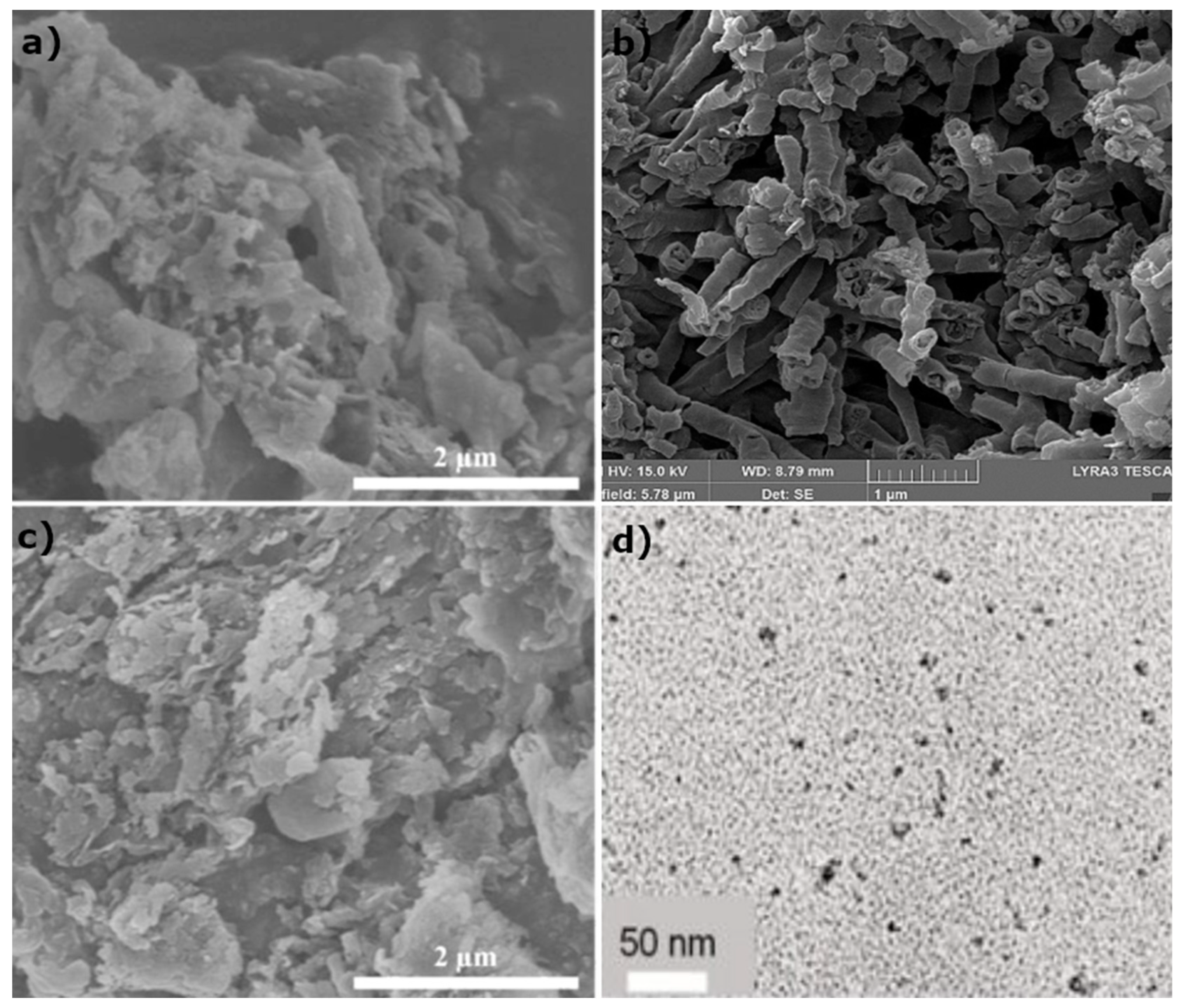
3.2. Surface and Morphological Characteristics

3.2.1. Scanning Electron Microscopy (SEM) and Transmission Electron Microscopy (TEM)

Scanning Electron Microscopy and Transmission Electron Microscopy are indispensable tools for verifying that the desired CN structure and properties have been achieved (Figure 4), further validating the choice of precursors and treatment method. Images of pure g-C3N4 produced by melamine exhibit extensive stacking of tri-s-triazine rings, indicative of the heavily agglomerated bulk phase produced by most synthesis methods reported [42,52]. In contrast, CN synthesized by urea calcination (e.g., 550 °C, 3 h, and 5 °C/min) is prone to forming wrinkled nanosheets [28]. Precursor choice is also an important factor as g-C3N4 prepared from melamine at a lower heating rate (e.g., 2 °C/min) consisted of small lumps surrounded by C3N4 sheets while using urea as a precursor produced more porous flake structures, significantly increasing the surface area [40].
Variations in synthesis conditions exert a significant influence on the structure of the CN produced [46]: higher calcination temperatures, combined with a steep temperature rate (e.g., 580 °C, and 15 °C/min), produce thin (nearly 10 nm) folded sheets, further aggregating into flakes. On the contrary, a slower heating rate results in a denser stacked flake structure of increased diameters (100–200 nm). Reduced calcination temperatures may also lead to the creation of porous CN structures initially, succeeded by the formation of compact bulk material [46]. An irregularly folded sheet morphology was detected on a CuInS2 QDs/CN binary composite after undergoing calcination at 520 °C [36,40]. As shown in [42], exfoliation temperature, treatment time, and atmosphere affect the structure of nanosheets: re-calcination in the air at 500 °C for 6 h resulted in a well-defined sheet structure, while at 560 °C for 2 h, it produced a porous sheet. Moreover, the CO2 atmosphere does not exhibit any advantages as it results in the same porous formation as higher temperature exfoliation.
The transitional metal salt-assisted re-crystallization process of melamine prior to calcination was researched in [72], and it was concluded that it can produce smaller-sized CN bulk particles, further assisting in tube formation by heat treatment. High-temperature conditions present during the solvothermal treatment of bulk g-C3N4 severely altered the material’s morphology, resulting in a thin sheet structure [52].
Electron microscopy also revealed that the selection of different exfoliation methods may result in the same nanosheet morphologies with distinct dimensions as the ultrasonic method results in large stacks of nanosheets, the hydrothermal method leads to sheet folding and aggregation into semi-clusters of CN layers and, lastly, thermal exfoliation produces the morphology of well-formed nanosheets [27]. This is in accordance with the findings of Liu et al. [66], who reported that thermal exfoliation can reduce the size of bulk g-C3N4 nanoparticles by up to three times when they are converted into single sheets (average thickness of 3 nm).
In CN nanosheet–nanotube composites, the sheets can function as a platform for CNT loading, which are dispersed throughout the sheet’s surface, hindering interlayer interactions and increasing the exposed surface area [27,28]. In a particular case, both pristine CN and Mo-doped CN nanotubes created by a multi-step method exhibited varying morphological characteristics in terms of length, diameter, and thickness. Pure CN nanotubes maintained smaller sizes in all dimensions, with a length ranging from half a μm to a few μm and a diameter of 150 nm. The integration of Mo-nanoparticles greatly changed the nanotube structure, even at low concentrations (5–15 wt%), resulting in an increase of ×5 for the length (5 μm) and ×3 for the diameter (500 nm) [41].
The presence of amino groups also affects the morphological characteristics of the integrated plasmonic nanoparticles, particularly their size. The introduction of co-catalyst nanoparticles in the surface of g-C3N4 can be observed as uniformly distributed bright or dark spots in many cases [52,63]. Surface noble metal loading has been shown to yield smaller sizes and improved homogenous distribution at low concentrations. In a recent study, a loading of 5 wt% resulted in a size less than 3 nm, while increasing the percentage led to greater sizes due to agglomeration and a higher number of metal clusters [57]. Finally, CN-derived quantum dots can achieve diameters lower than 10 nm. Smaller diameters are beneficial for anchoring QD to the CN sheet surface by π–π interactions [28]. More interestingly, in the case of CNT/CN/WO3, the distortion of the semiconductor nanosheets occurred during loading, resulting in butterfly-like formations, indicating the complex mechanisms behind the creation of ternary composites [27].

3.2.2. Brunauer–Emmett–Teller (BET) Analysis

BET examination has been conducted by most researchers to evaluate the surface morphology and porous characteristics of solid catalysts through the creation of adsorption–desorption isotherms, including composite photocatalysts. N2 adsorption is a common choice among researchers for the determination of specific surface area, pore volume, and pore size of graphitic-enhanced photocatalysts [27,52]. Higher specific surface area and pore volume create ideal conditions for adsorption [46]. Table 6 shows the expected values for g-C3N4 according to recent works. The alteration from bulk-stacked layers to sheet formation increases g-C3N4’s specific surface area ([32,52]). Furthermore, pore size and pore volume can be greatly enhanced during such morphological transitions [52], both of which can greatly contribute to the photocatalyst’s efficiency during water splitting reactions. Most morphologies of g-C3N4 [51] as well as composite systems created with it as a base catalyst [30,32,79] demonstrate a type-IV isothermal curve and micro–mesoporous nature. A recent study [46] demonstrated that the adsorption efficiency of g-C3N4 is enhanced with the escalation of the calcination temperature under a consistent heating time and rate. When subjected to identical calcination temperatures, the porosity of the specimen fabricated through a swift heating rate surpasses that produced by a slower heating rate.
Bulk CN’s unexfoliated layers translate to a smaller specific surface area, bigger pore diameter, and restricted N2 adsorption under lower pressures compared to its nanosheet and nanotube counterparts [27,51]. Wrinkled sheets of CN can also exhibit similar specific surface area to bulk CN [28]. The exfoliation method is shown to have a direct effect on the porosity and specific surface area of CN nanosheets, with thermal exfoliation yielding better results, followed by ultrasonic and hydrothermal methods [27]. Thermally exfoliated CN can show a multi-fold increase in specific surface area. Ultrasonic exfoliation also has merit when it comes to the adsorption capacity, surpassing even thermal CN values at higher pressures, although this cannot be considered an asset over the latter as photocatalysis focuses on adsorption at lower pressures [27]. Ultrasonicated CN’s specific surface area is improved over bulk CN’s by a significant factor. CN nanosheets treated hydrothermally can reportedly achieve performance comparable to bulk CN, with negligible improved specific surface area and N2 adsorption [27]. These findings indicate that aggregated CN layers formed during hydrothermal processes essentially function similarly to pristine bulk CN.
In the case of doping thermally exfoliated CN nanosheets with WO3 and CNT, its adsorption–desorption capabilities and surface-to-volume ratio were augmented, contributing to enhanced H2 production [27]. The same results can be obtained by CNQD or CNT doping of CN, with the latter showing slightly lower improvement of specific surface area [28].
Noble metal deposition on the CN surface can positively affect the increase in surface area [32,50]. In a recent study, porous nanotubes of CN with increased N vacancies and Cu nanoparticles exhibited enhanced surface area as well as pore volume, making them ideal for photocatalytic applications [50]. As reported in [80], nitrogen-deficient CN with S-doping also exhibited improved adsorption capabilities. The mesoporous hollow tubular structure can also be achieved via the opposite route, from N-doped CN, again demonstrating the same enhanced attributes, which greatly contribute to photocatalysis [51]. Compared to noble metal loading, chemical exfoliation can yield more efficient results in increases in specific surface area [32]. Composites of CN with other semiconducting materials do not always possess enhanced adsorption capabilities, e.g., in the case of CuO/CN, which experienced a reduction in its specific surface area with increased concentrations of metal oxide up to 2 wt% [30].

3.3. Optical–Electrical Properties: Improvement Methods

3.3.1. Ultraviolet-Visual Spectrometry (UV-Vis): Light Response

Arguably, when referring to composite photocatalyst synthesis, the most important factor is the ultraviolet and visual absorption spectrum because the photocatalytic activity of a material mainly depends on its light harvesting abilities. A material’s band gap defines the feasibility and effectiveness of its usage as a photocatalyst. A combination of UV–vis, Kubelka–Munk function, and Tauc plots is usually employed [27,41,52] to theoretically determine the band gap of newly formed photocatalysts. Then, with the use of data previously acquired through XPS analysis about the VB potential, the band structure of each material can be adequately described.
Pristine graphitic carbon nitride’s (g-C3N4) absorption band edge sits approximately at 440 nm [36,61], and its band gap is found to be close to 2.7 eV, as reported in [28,82], although this value can vary across different studies, with some reporting values near 2.72 eV [41] or 2.81 eV [36]. Valence band (EVB) and conduction band (ECB) potentials of g-C3N4 are around 2.15 V and −0.66 V (vs SCE), respectively [36].
CN samples fabricated through slower heating rates exhibit a smaller change in the absorption band edge in contrast to those generated via quick heating. Longer heating times and elevated calcination temperatures are related to band gap reduction. Rapid heating rates force the band edge to red-shift, attributable to the formation of a more aggregated stacked structure [46]. Nanosheets and nanotubes show a blue shift in the absorbance edge [66,73] and increase in the band gap via all exfoliation routes, in comparison to bulk CN. This common blue shift in the absorption edge is ascribed to the presence of a quantum confinement effect (QCE) as a product of passing from 3D morphology to 2D morphology, which restricts electron migration on the sheet’s surface [27]. QCE is most prominent in quantum dots, significantly improving their quantum yield [29]. Although that may not always be the case, if re-crystallization takes place prior to nanotube synthesis, the products experience a greater band gap reduction compared to bulk CN, which further decreases with the addition of metal ions (e.g., Fe3+) [72].
The presence of surface amino groups can have a diminishing effect on g-C3N4’s band gap, leading to a value of 2.33–2.44 eV [52,72]. Metal doping at relatively low concentrations (e.g., 5 wt%) can have a positive impact on band gap reduction; nevertheless, that does not seem to be the case for higher values (e.g., 15 wt%) due to band gap widening, which diminishes visible light response [41]. Precious metal co-catalyst addition can induce red shifting of the g-C3N4 band edge and diminish the band gap energy [10], attributable to positively charged ions located at N vacancies of the surface [83]. In [10], the increasing concentration (up to 2 wt%) of the co-catalyst exhibited an improved red-shifted edge, accompanied by band gap shrinkage. In a special case [73], the addition of a plasmonic metal in CN led to a weak plasmonic absorption peak and did not enhance the light absorbance of the produced material but instead blue-shifted the band edge. It was hypothesized that this was due to the small size of the plasmonic particle (Au), which can act as an electron trap.
Semiconductor-CN binary nano-composites exhibit increased light absorption in the 300–700 nm spectrum [36]. The optical properties of binary and ternary composites, encompassing all-graphitic materials, were researched by the authors of [28], who concluded that the integration of carbon nanotubes on the surface of g-C3N4 sheets red-shifted band edge and reduced the band gap compared to pristine CN (from 2.78 eV to 2.73 eV). The incorporation of CN QDs accentuated this result further (2.65 eV). Metal oxide–CN composites also appear to have an improved red-shifted band edge, as reported for a NiTiO3 combination with CN nanosheets [61]. Doping CN with non-metal elements (S, P, F, and Br) also has a positive outcome [79], with all combinations showing a red-shifted absorption edge. Heterojunction formation between these materials and boron-doped nanodots did not have the expected outcome as BCNDs had a minimal effect on the improvement of the composite’s light harvesting abilities.

3.3.2. Photo Luminescence Steady-State and Transient Spectroscopy: Recombination Prevention

Steady-state and transient PL spectroscopy are widely used during photocatalyst characterization to determine light reactivity and charge carrier recombination rate and efficiency. During PL analysis, specimens undergo illumination under UV [61,66,84] or visible light [40]. Incident light creates electron–hole separation, which are then recombined, emitting energy that is measured. Higher peaks are translated as increased charge carrier recombination indicators, showing poor reactivity of the material during visible light illumination. In contrast, lower peak intensities indicate extended periods of charge carriers remaining in separate modes. In this state, free-moving electrons are more likely to migrate and react with other chemical species in the solution through the catalyst’s surface. In conclusion, a higher PL peak intensity is indicative of lower-efficiency photocatalysts.
g-C3N4 derived from different precursors (melamine/urea) behaves differently during TRPL analysis, as discussed in [40]. Strong non-radiative emission of π–π networks contained in urea CN rapidly reduces its luminescence compared to urea-produced CN. The heating rate was also found to affect the luminescence of urea CN, with lower rates relating to lower fluorescence, leading to an increased lifetime of charge carriers. Under the same heating rate, melamine-synthesized CN exhibited even lower fluorescence. Pure g-C3N4 nanotubes exhibit high emission peaks during PL analysis due to a limited charge carrier lifetime before recombination and lower charge transport rates [41,52]. Gao et al. [47], demonstrated that the transition from bulk to nanotube structures has a twofold effect on fluorescence: (a) increase in re-emission caused by charge carrier recombination and (b) faster migration speed of electrons due to 1D morphology (also being the cause of the increased recombination). Urea modification of g-C3N4 sheets follows the law of diminishing returns as treatment with small amounts of urea (0–10%) is able to result in increased photoexcited charge carrier separation, although increased amounts have the opposite effect, lowering its efficiency closer to that of pure g-C3N4 [52].
The recombination rates of composite systems could be hindered by metal ion loading (e.g., Ni) at relatively small concentrations (e.g., until 7.5 wt% for Ni) [82]. Fe3+-doped CNTs, created by re-crystalized melamine also showed significantly lower light emittance, indicating the importance of metal ion integration in suppressing electron–hole recombination and faster electron movement [72]. Similarly, Mo integration on CN nanotubes significantly improved photocatalytic efficiency by shifting the maximum absorption peak within the visible light region, as shown by photoluminescence spectroscopy [41]. The introduction of semiconductor quantities in small concentrations (e.g., 5–10 wt%) on binary composites such as CuInS2/CN [36] and CoS2/CN showed a continuous decrease in re-emission intensity due to charge carrier recombination hindering and shortened electron–hole separation times [36,84].
The doping of CN nanosheets with WO3 nanosheets seems to amplify electron–hole separation, with the addition of CNT nanoparticles as co-catalysts showing little improvement [27]. From the results of all-graphitic ternary composites (CNQDs/CN/CNTs), it is evident that CNQDs and CNTs incorporation onto CN sheets can effectively limit photoinduced charge carrier recombination [28]. A similar trend can be observed for precious metal loading as in [10,83], where co-catalyst Pt nanodots decreased the charge carrier resistance and increased the separation efficiency of an N-deficient CN up to concentrations close to 1 wt%. The same effect was reported in [10] using S and N co-doped CN, with lower concentrations of Pt and the apparent suppression of electron–hole recombination being attributable to efficient electron transfer due to the coordination of non-metal atoms.

4. Mechanism of g-C3N4 in Photocatalytic Composites and Applications

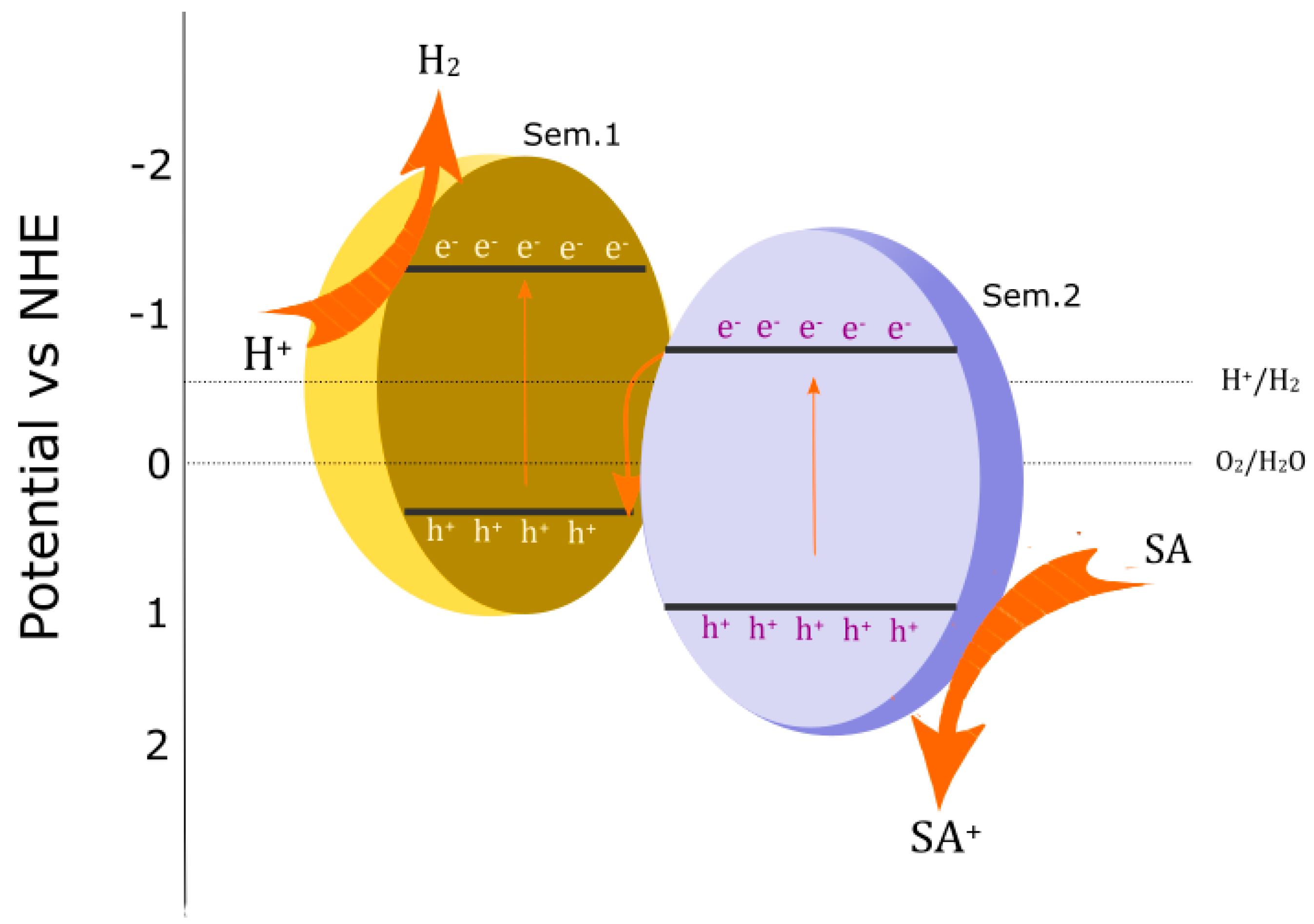
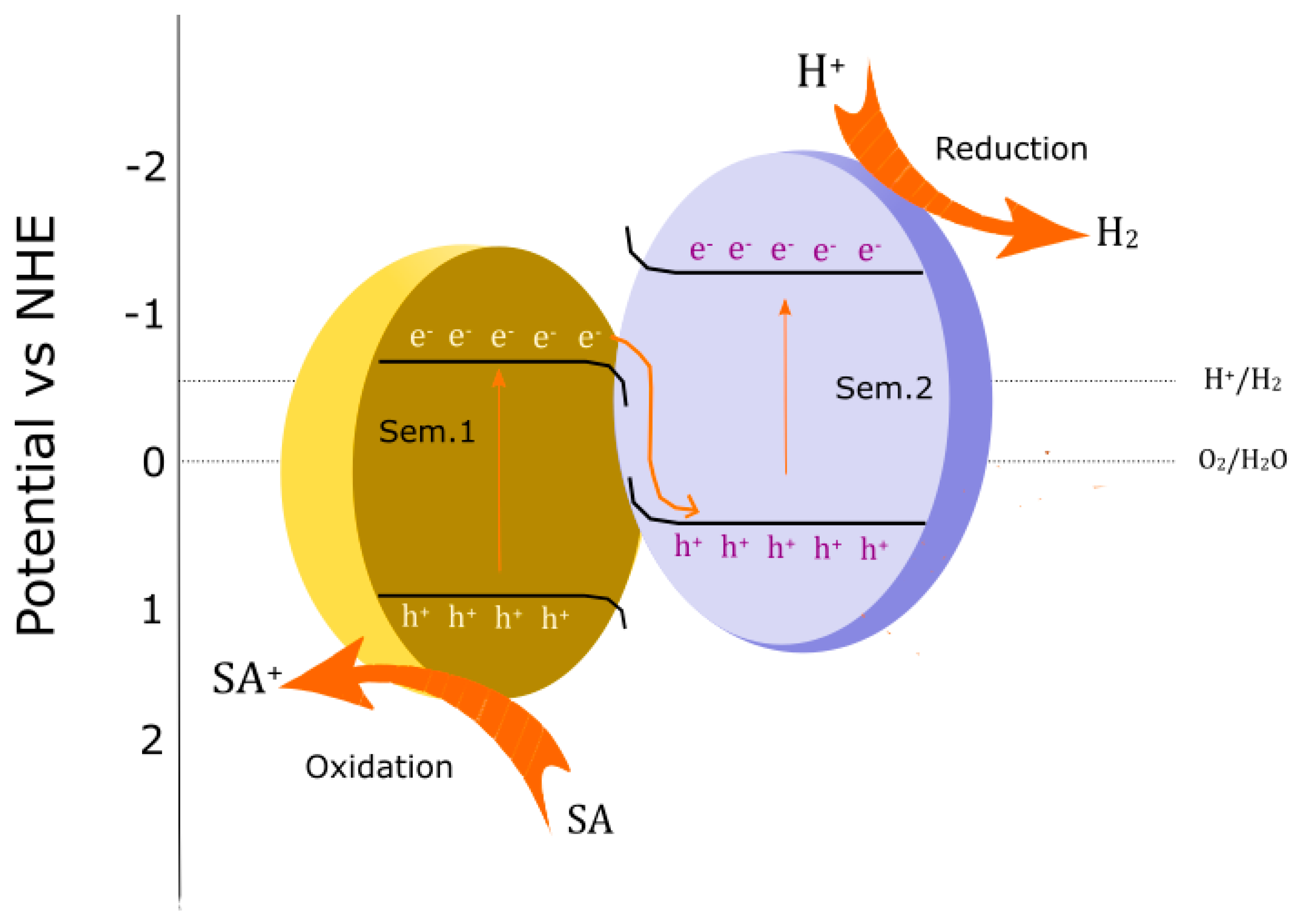
4.1. Basic Mechanism of Water Splitting

Water splitting refers to the sum of two half-reactions (3) taking place at different sites of the photocatalyst during light irradiation, which result in the production of hydrogen and oxygen gases (Figure 5). Hydrogen evolution reaction (HER) (2) occurs at reducing active sites (analogous to a cathode), transmitting electrons from the catalyst to free-roaming hydrogen protons (H+), which combine to form H2. Oxygen evolution reaction (OER) (1) occurs at oxidizing active sites (analogous to an anode), receiving electrons from H2O molecules, which split into H+, free electrons, and O2. The water splitting reaction is endothermic; therefore, it cannot occur spontaneously (ΔG0 > 0), and H2/O2 stability is favored.
Photocatalysts act as an intermediate, transforming incident light energy into electrons, thus constituting the hydrogen–oxygen production feasible. This is only possible in cases where the band gap of the catalyst overcomes the minimum threshold (+1.23 V vs. NHE at pH = 0) needed [41,85]. Both half-cell reactions are seen below, along with the complete reaction [86].
2H2O → O2 + 4H+ + 4e, E0 = +0.81 V vs. NHE at pH = 7
2H+ + 2e → H2, E0 = −0.41V vs. NHE at pH = 7
H2O → H2 + O2
Energy band positions of a material determine if it can effectively function as a photocatalyst under irradiation. The valence band maximum must be higher than the OER potential, and the conduction band position must be lower than the HER [57]. The positions of energy bands can be altered through doping and pH modification [56]. As for g-C3N4 (Table 7), its band gap energy is close to 2.78 eV [30], and the valence band and conduction band potentials are positioned near 1.9 V And −0.748 V, respectively [28].
The transition from a g-C3N4 stacked sheet to a tube architecture is expected to alter the band gap by increasing it, according to [47]. Additionally in [74], an increase in band gap was observed during the transition from hexagonal columnar crystals to hollow nanotubes. This observation is explained by the pronounced quantum confinement effect that 1D nanotubes exhibit over 3D bulk morphology [73].
The structural modification of CN without the addition of dopants leads to band gap widening. The dimensionality of electron migration routes is diminished, owing to the quantum confinement effect (QCE) [42] as g-C3N4 samples transition from 3D multi-layered formation to 2D sheets, 1D tubes, and 0D nanodots. As reported in [46], calcination at high temperatures for extended periods can reduce the band gap. Slow heating rates can also result in a minor decrease (e.g., from 2.61 eV to 2.55 eV), while rapid ones can red-shift the absorbance even further (e.g., 2.42 eV). The exfoliation of stacked sheets does not seem to have any major effect on g-C3N4’s band gap, with values being reported close to those of its bulk form [28]. However, as reported by Vega et al. [42], thermal exfoliation produces an increased band gap, which positively affects the low recombination rates. Moreover, samples produced under air and CO2 atmospheres resulted in different energy bands, with gaps of 2.76 eV and 2.98 eV, respectively. In [47], a short (5 min) calcination process at 550 °C resulted in a nanotube morphology and also increased the band gap by 1.1 eV compared to the simple bulk form. Moreover, the nanotube’s CB position was slightly more negative compared to bulk CN, also attributable to the distinct morphology.
Composites encompassing bulk forms of g-C3N4 experience a band gap decline due to heterojunction formation. Compactly coupled CuO and g-C3N4 bulk particles have shown a band gap reduction compared to pristine g-C3N4 [30]. CN nanodot incorporation in all-carbonaceous ternary systems has been observed to aid in shrinking the band gap of CN nanosheets by a small amount. The band gap only showed a decrease with the further addition of carbon nanotubes (CNTs) [28].
The doping of nanosheets can diminish the band gap energy, as in the case of S-doping, where the initial 2.7 eV gap was reduced to 2.64 eV. In a recent study, CN doping with equal amounts of S and P created hollow nanotubes with an increased band gap and, interestingly, the band gap continued to widen with an additional dopant content up to 0.5 wt% [60]. In another work, 5% Mo-CN nanotubes possessed a band gap of +2.63 eV, which was sufficiently high to supply the needed latent heat energy for the two reactions [41]. The band gap decreased ( from g-C3N4 (2.8 eV) to S/g-C3N4 (2.75 eV) and to Mo/S/g-C3N4-10 (2.5 eV), which corresponded to the red-shift trend of the intrinsic absorption edge. However, the band gap of Mo/g-C3N4 increased to 3.0 eV [77].

4.2. Function of Structurally Modified g-C3N4 in Photocatalytic Mechanisms

CN can function solely as a photocatalyst with limited results [47]. Electrons can migrate to active sites and react with H+ species, leaving a surplus of positively charged holes to populate different sites of the same surface and initiate the oxidation reaction. Surface amino groups are a main contributor to the enhanced photocatalytic capabilities of g-C3N4 [52]. As discussed, a high-temperature treatment, extended heating time, and rapid heating rate within the acceptable ranges, to avoid structural disintegration, can result in increased surface area, crystallinity, porosity, and presence of amino groups, all of which enhance photocatalytic activity [46]. The aggregation and distortion of g-C3N4 sheets form a cavity-rich morphology, where light refractions and reflections improve visible light utilization [53].
The function of the amino groups as hole stabilizers has also been observed to result in efficient charge carrier separation and extended exciton lifetime both of which greatly contribute to the photocatalytic potency of composite materials. As mentioned previously, these specific groups can reduce the co-catalyst particles’ size, augmenting visible light activation of the composite material through the plasmonic resonance effect. During visible light excitation, electrons overcome the band gap energy and occupy the CB while leaving positively charged holes in the VB. Electrons’ migration to the surface of the material is further facilitated by the synergistic effect of all previous contributions, resulting in the electron reaching the surface through loaded noble metal (M) particles at neutral oxidation states (M0) and participating in the reduction in hydrogen protons. Complementary oxidation reactions, which are mandatory in order to avoid the depletion of the catalyst’s charge, occur between the sacrificial agent (TEOA in most cases [53,66,72]) and positively charged noble metal ions (Mδ+) [52].
Nanotubes comprise a suitable platform with a high specific surface area and enhanced kinetics of charge diffusion, further aided by integrated metal atoms, which solidify efficient electron–hole separation and inhibit e/h+ recombination [41]. Moreover, CN nanotubes’ hollow structure causes multiple refractions and scattering of incident light within the tubular structure, increasing light absorption efficiency [64]. Due to the curving of 2D sheets to 1D tubes when transitioning from sheet formations to nanotubes, -NH2 groups previously contained within the g-C3N4 plane are then more exposed on the tube’s surface due to structural bending. Extended exposure of -NH2 groups causes charge density changes, improving interactions with hydroxyls in water molecules and charge transfer [72].

4.3. Function of g-C3N4 in Composites

In type-II heterojunction photocatalysts (Figure 6), the conduction band (CB) and valence band (VB) energy levels of semiconductor 1 are higher in comparison to those of semiconductor 2. During light exposure, the independent generation of electron–hole pairs in both semiconductors takes place. The photogenerated electrons from semiconductor 1 migrate towards the conduction band of semiconductor 2. At the same time, the generated holes move towards the semiconductor 1 valence band. H+ cations receive electrons from active centers located on the surface of semiconductor 2 (reduction), and electrons from the molecules of the sacrificial agent are transmitted to the valence band of semiconductor 1. The type-II heterojunction mechanism suffers from limited efficiency due to the constant depletion of charge carriers in both semiconductors [87]. Despite its inherent limitation, in a recent work, the composite constructed by loading ZnIn2S4 nanosheets onto S-doped g-C3N4 nanosheets performed efficiently, even after three cycles of photocatalytic activity, producing a max of 570 μmol g−1h−1. In this case, g-C3N4 acted as the reducing agent [70].
The Z-scheme (Figure 7), now widely implemented in photocatalytic systems, is influenced by photosynthesis [87]. A Z-scheme heterojunction is formed at the intersection of two semiconducting materials that exhibit an interchanging placement of energy band levels. Semiconductor 1, with lower energy band potentials, acts as a reduction site, and semiconductor 2, with more positive potentials, acts as an oxidation site. During visible light excitation, the electrons on the semiconductor 2 conduction band (CB) are transmitted to the valence band (VB) of semiconductor 1 and recombine with pre-existing holes [29]. The holes on semiconductor 2’s CB and electrons on Sem1’s CB start to accumulate. The reduction in H+ species is initiated at semiconductor 1’s surface, while sacrificial agent molecules are oxidized on the surface of semiconductor 2 [61]. The use of a co-catalyst molecule, loaded onto semiconductor 1 surface and contributing to enhanced electron migration through additional active reduction sites, is very common [49].
g-C3N4 has received considerable attention for its capacity to act as a reduction semiconductor in binary and ternary composites because it has more negative values of VB and CB than most metal oxide semiconductors [87]. In ternary composites, graphitic nanoparticles can supply the base structure (most common structures for this purpose being bulk, nanosheet [78], and nanotubes), facilitating metallic or non-metallic nanoparticle loading and functioning as co-catalysts in the form of nanotubes [27] or nanodots [29]. In [27], WO3 was loaded onto CN nanosheets, creating a Z-scheme heterojunction with extended band gap energy, with additional CNTs contributing to elevated light absorbance, band gap narrowing, and red shifting towards the optical spectrum due to its electron confining capabilities. Nevertheless, electrons and holes generated from this scheme possessed inferior redox abilities [88].
S-scheme heterojunction (Figure 8) is a novel approach, producing powerful photogenerated charge carriers [88]. S-scheme heterostructures typically consist of n-type semiconductors [80], where the oxidizing side exhibits a higher work function and lower Fermi level, while the reductive material has a smaller work function and higher Fermi level. Electron migration is directed from the reducing to the oxidizing semiconductor. Energy band bending occurs at the interface of two materials, causing Fermi levels to equalize [64]. Energy band bending causes charge carrier recombination, except for electrons in the CB of the reductive material and holes on the VB of the oxidizing material. S-scheme heterojunctions are constructed by staggered band structures [88]. These agents possess enhanced reduction and oxidation efficacies, taking part in subsequent water splitting reactions [36].
During light illumination, electrons from the CB of semiconductor 1 migrate to the VB of semiconductor 2. A shortage of electrons causes even more electrons to transmit from the VB to the CB of semiconductor 1. A negative charge is accumulated on the VB of semiconductor 2, and similarly, more electrons move to the CB in semiconductor 2. This mechanism effectively creates a positive charge on semiconductor 1, which acts as an oxidation site, and a negative charge on semiconductor 2, acting as a reduction site [64]. Graphitic carbon nitride’s appropriate oxidation and reduction potentials make it a suitable candidate for constructing an S-scheme-based heterojunction [61].
Doping is an effective solution to fine-tune g-C3N4 energy bands. An S-scheme-functioning all-CN composite was realized by Wang et al. [80]. A heterojunction was formed between N-defective g-C3N4 and S-doped g-C3N4, with the first facilitating oxidation and the second facilitating reduction. The successful construction of this catalyst was made possible thanks to the relocation of g-C3N4 energy bands to more negative values and a tightened band gap (2.68 eV), which were both attributed to S-doping. In some cases, CN, which participates in S-scheme heterojunctions, presents a negative character associated with electron gain and thus undergoes a downward band bending during Fermi level adjustments. On the other hand, a semiconductor such as CuInS2 can experience an upward band bending due to the presence of more holes [36]. Nevertheless, CN in other composites (e.g., NiTiO3@CNT) can function as a reducing agent, experiencing upward band bending [61,64]. The folded lamellae nanostructure of g-C3N4, enhanced with ZnIn2S4 nanodot deposition, is another example of composite material function under an S-scheme. CN assumed the role of an oxidizing agent again in this work [89]. Currently, many examples of g-C3N4 based S-scheme heterojunctions exist in the literature, including 3D/2D NiCo2O4@g-C3N4 (CN acting as an oxidation site) [44] and ternary 2D CN/2D boron-doped CN/CN (with CN acting as an oxidation site and boron-doped CN acting as a reduction site) [90].
The supply of electrons through the catalyst’s surface helps drive the water splitting reaction of 2H + 2e → H2. The continuous migration of negatively charged particles to positively charged hydrogen protons results in the depletion of the photocatalyst. To mitigate this effect a sacrificial agent (usually organic compounds) is employed to react with photoinduced holes. Organic molecules can function as such. Common sacrificial agents include methanol, ethanol triethanolamine (TEOA) [10], ethylene glycol [28], methylene blue (MB) [46], and Rhodamine B (RhB) [60].
Co-catalysts, either loaded onto the surface of the main catalyst [52,57] or dispersed into the final testing mixture [28,29], are used as a means to accelerate the charge transfer from the main catalyst to the co-catalyst by forming a Schottky barrier, impeding photogenerated electron–hole recombination [72]. As observed in most recent works, Pt nanoparticles are a common choice for a co-catalyst [42,52,72], although the usage of other metals such as Au [32] and Cu [57] have also been reported.
Plasmonic metal particles display enhanced light harvesting abilities due to the LSPR (Localized Surface Plasmon Resonance) effect. In a conducting nanomaterial, surface plasmons are regarded as the coherent oscillation of its unbound charge, localized at its surface. When exposed to light irradiation, the unbound electrons of a metallic nanoparticle become polarized as a result of the electric field of the incident light. If the frequency of the incident light is equal to the plasmon frequency, it can lead to the occurrence of an absorption resonance, resulting in the generation of intense electric fields on the surface of the nanoparticles [56]. The introduction of plasmonic nanoparticles into semiconductor and semiconductor composites results in the drastic improvement of their light harvesting abilities and promotes electron charge transfer for effective photocatalytic water reactions (Figure 9). Au [32], Ag, Cu, Pt, Pd, and Rh [30] have all been used for this application. Pt loading has a profound effect on g-C3N4 hydrogen production capabilities. In a recent work, S-doped nanotubes were found to be nearly inactive under visible light irradiation. The integration of finely dispersed Pt atoms on their surface resulted in improved hydrogen production until a threshold of 0.4 wt%. A further increase in Pt atoms diminished the photocatalytic efficiency due to the agglomeration of Pt atoms in nanoparticles [10].

4.4. Comparative Overview of Hydrogen Production by g-C3N4-Based Materials

Hydrogen production in most research works has been carried out in a simple experimental setup. The fabricated sample is dispersed in a solution of sacrificial agent [44,53,66] in water. The mixture is inserted in a glass vessel, with its entrance connected to an inert gas (e.g., N2 and Ar) tank, and the exit connects to a gas chromatographer accompanied by a thermal conductive detector. Depending on the type of testing, a noble metal solution such as H2PtCl6 may also be dispersed in the sample to act as a co-catalyst by direct photoreduction in the system. Prior to testing, the system is degassed with inert gas to remove the air. Then, the system is irradiated by a light source. A more complex setup such as a glass closed-gas circulation system was reported in [57]. Quantum efficiency (QE) is estimated under mono-chromatic light irradiation (420 nm (±10 nm)).
A general view of the capabilities of CN-based materials in hydrogen production can be seen in Table 8. Bulk g-C3N4 synthesized by calcination without the addition of a co-catalyst exhibits production values inferior to 20 μmol h−1g−1 [52,60]. The addition of a co-catalyst in the final sample is able to improve the photocatalytic efficiency but continues to have low hydrogen production rates, which are attributed to poor charge carrier separation [66]. The amorphous bulk g-C3N4 produced in [68] had poor photocatalytic efficiency, attributable to numerous hydrogen bonds and interlayer van der Waals forces. As a result, electron migration was localized, and only a small portion reached the surface. On the other hand, nanosheet morphology with a width of a few nanometers greatly improved the charge carrier supply to the surface of the material. A recent study on g-C3N4 flakes produced by both melamine and urea [40] indicates that samples prepared at 550 °C for 4 h at a ramp rate of 2 °C/min were more photocatalytically active than samples prepared under different conditions, with urea showing superior results over melamine.
Exfoliation resulted in nanosheets with enhanced photocatalytic behavior over their bulk counterparts [66]. Pristine nanosheets can be used as photocatalysts without further modifications, exhibiting satisfactory photocatalytic performance in visible light conditions. The results are heavily influenced by the distinct sheet structures obtained through different conditions and methods of synthesis, varying from 44 μmol h−1g−1 [32] to 280 μmol h−1g−1 [57]. However, further improvement is hindered by the rapid recombination of photoinduced charge carriers and the inherent instability of those carriers [57]. As previously detailed, the choice of the exfoliation strategy for prefabricated g-C3N4 can affect the final nanosheet structural form, and in turn, the light harvesting abilities [68]. Thermal exfoliation appears to be the most promising method, achieving improved results compared to the bulk form [57]. The addition of co-catalytic particles on the surface of nanosheets seems to promote them further, with maximum values reaching 526 μmol h−1g−1 [57] to 6137 μmol h−1g−1 [27].
The direct modification of g-C3N4’s surface with closely related substances such as urea, aiming to integrate amino groups, while proving to have a favorable effect on electron–hole separation, hole stabilization, and band gap energy reduction, has a limited effect on improving the hydrogen production process itself. Even in studies that focused on the previous strategy, a co-catalyst (e.g., Pt) has been deemed a more efficient method of increasing hydrogen production [52]. The doping of bulk samples with P while using Pt as a co-catalyst greatly improved the results, reaching production rates near 400 μmol h−1g−1 [66]. An interplay between extra amino groups on the surface of g-C3N4 and the integration of a plasmonic co-catalyst yielded highly improved hydrogen production because of the extended charge carrier lifetime and excellent mobility facilitated by on-site metallic particles [52]. In another recent work, co-doping of CN nanotubes greatly increased the photocatalytic efficiency, leading to the rapid degradation of Rhodamine B (RhB) by 90% in lake water solution after 30 min. Hydrogen production was measured at 8163.5 μmol h−1g−1, greatly surpassing that of pure CN (20.5 μmol h−1g−1) [60]. The addition of amino groups on the catalyst’s surface significantly changed the species of the integrated Pt nanoparticles, increasing the number of more negative Pt0 instead of the more positive Ptδ+ nanoparticles. Populating the surface of the graphitic material with particles containing readily available electrons aids the water molecule reduction efficiency of the photocatalyst, as shown in [52]. Oxidized Pt2+ nanoparticles contribute to the prevention of hydrogen back-oxidation [83].
When a stacked nanosheet structure was combined with TiO2, (one of the most used semiconductors in photocatalysis) and a Ni co-catalyst, the production rate reached 131 μmol h−1g−1 [91], close to that of 1.5 wt% CuO/CN bulk [30]. Arguably, this could indicate the inability to surpass bulk form charge carrier limitations despite having a composite design. A complex ternary structure synthesized by loading WO3 nanosheets/CNTs onto CN nanosheets demonstrated an incredible rate of 11,520 μmol h−1g−1. The addition of carbon nanotubes in the composite to act as nano-cables for efficient e transport greatly contributed to achieving this result [27]. An H2 production rate of 799.2 μmol g−1 h−1 was achieved by type-II homojunction formation between amorphous and crystalline g-C3N4, achieving considerably improved results over its counterparts [68]. It is worth mentioning that ternary all-graphitic composites produced increased quantities compared to bulk CN, with ternary composite CNQDs/CN/CNTs showing significant improvement, while binary composites (CNTs/CN sheets, CNQDs/CN sheets) showed a smaller increase [28].

5. Challenges, Perspectives, and Conclusions

Conclusively, many possible routes for efficiently improving g-C3N4 have been reported in the last few years, denominating its incredible versatility as a photocatalytic material for hydrogen production and other applications. The thermal calcination treatment appears to be the most efficient method for the synthesis and structural modification of g-C3N4. Calcination conditions play a pivotal role in structural formation. Heating temperatures close to 550 °C are the most common choice as higher temperatures will result in lattice disintegration and lower temperatures are not enough for complete polymerization. Methods encompassing additional calcination steps (exfoliation included) will result in more defined 2D and 3D structures. The heating time reported is usually a few hours, although shorter heating times could be a viable option; however, this needs to be investigated further. Surprisingly enough, products formed by increased ramp rates, which hinder homogenous heating, result in better photocatalytic structures.
Bulk CN provides short migration routes and reduced interplanar transport for charge carriers, as well as a small specific surface area. Structural modification producing sheet (e.g., flakes) and tube-like morphologies can resolve this matter by dimensional reduction. Sheets allow enhanced in-plane electron movement, and tubes act as nanoscale wires, allowing only 1D movement. These properties improve their light harvesting abilities. Nanosheets are most encountered as base catalysts, while nanotubes are sparsely used as co-catalysts in composite systems. Nanodots, on the other hand, require a different synthesis method, involving acids, and usually act as co-catalysts instead of metal ions.
The exposure of amino groups on the surface of g-C3N4 provides minor charges in hydrogen production but creates suitable bonding positions for non-metal and plasmonic metal decoration. Doping with non-metal atoms such as P and S can positively affect tubular formations and hydrogen production. Porous structures possess improved light trapping harvesting abilities due to the existence of cavities such that light is scattered inside the structure of the catalyst. Increased specific surface area can be achieved in many ways, including higher temperature treatment (low enough to avoiding lattice disintegration), increased heating rates, non-metal doping composite formation, and co-catalyst integration. g-C3N4 can be used as both an oxidizing agent and a reducing agent in composite materials, depending on the selection of the added material, and is suitable for any heterojunction scheme due its energy levels and band gap. Although structural modifications are essential for g-C3N4 to have an effectively high surface area and long charge carrier migration, the morphologies of lower dimensions increase the band gap value. In most cases, g-C3N4 acts as an ideal basis for photocatalytic systems, and the integration of other species contributes to a narrower band gap, lower recombination rates, and additional surface routes for electron transmittance. More notably, the addition of a co-catalyst, especially plasmonic metals, results in the immediate and significant increase in hydrogen production. Nevertheless, this does not seem to be typical as there are composite materials capable of reaching high production rates without plasmonic metal integration (e.g., WO3/CNT/g-C3N4). The challenges that remain in the field of g-C3N4 are the standalone effectiveness of the carbonaceous material and the increase in efficiency of basic g-C3N4 through synthesis optimization in order to avoid dependance on added noble metals or semiconductors. Another goal concerning synthesis methods is their optimization with respect to cost-effectiveness and time by focusing on the improvement of one-step methods instead of the usual multi-step protocols. Furthermore, a perspective regarding synthesis is the standardization of protocols for the preparation of all basic forms of g-C3N4 for their acquisition with standard expected properties. Finally, while there has been a great deal of research in the area of morphological modifications, doping, and composite formation, the next area of research on g-C3N4 should focus on the synergy between all these methods. We can conclude that further research into the efficient combination of different types of modification is needed for significant advancement is needed for this promising material.

Author Contributions

P.K.: conceptualization, investigation, data curation, visualization, and writing—original draft; E.H.: conceptualization and draft revision; and G.V.B.: conceptualization, draft revision, and supervision. All authors have read and agreed to the published version of the manuscript.

Funding

This research received no external funding.

Conflicts of Interest

The authors declare no conflict of interest.

References

  1. Sun, R.; Wang, X.; Gao, Y.; Yao, Y.; Xin, L.; Wang, D.; Wang, Y. Rapid charge migration of hierarchical S-Scheme g-C3/N4/CdS@C for efficient photocatalytic hydrogen evolution. Int. J. Hydrogen Energy 2024, 55, 635–644. [Google Scholar] [CrossRef]
  2. Emran, M.Y.; Miran, W.; Gomaa, H.; Ibrahim, I.; Belessiotis, G.V.; Abdelwahab, A.A.; Othman, M. Ben Biowaste Materials for Advanced Biodegradable Packaging Technology. In Handbook of Biodegradable Materials; Springer International Publishing: Cham, Switzerland, 2022; pp. 1–37. [Google Scholar] [CrossRef]
  3. Acheampong, A.O.; Opoku, E.E.O. Environmental degradation and economic growth: Investigating linkages and potential pathways. Energy Econ. 2023, 123, 106734. [Google Scholar] [CrossRef]
  4. López, L.R.; Dessì, P.; Cabrera-Codony, A.; Rocha-Melogno, L.; Kraakman, B.; Naddeo, V.; Balaguer, M.D.; Puig, S. CO2 in indoor environments: From environmental and health risk to potential renewable carbon source. Sci. Total Environ. 2023, 856, 159088. [Google Scholar] [CrossRef]
  5. Wang, J.; Azam, W. Natural resource scarcity, fossil fuel energy consumption, and total greenhouse gas emissions in top emitting countries. Geosci. Front. 2024, 15, 101757. [Google Scholar] [CrossRef]
  6. Stathopoulos, N.; Belessiotis, G.; Oikonomou, P.; Papanicolaou, E. Experimental investigation of thermal degradation of phase change materials for medium-temperature thermal energy storage and tightness during cycling inside metal spheres. J. Energy Storage 2020, 31, 101618. [Google Scholar] [CrossRef]
  7. Belessiotis, G.V.; Ibrahim, I.; Falaras, P. Sensitizer effects on DSSC performance under pan-illumination conditions. J. Photochem. Photobiol. A Chem. 2022, 433, 114201. [Google Scholar] [CrossRef]
  8. Belessiotis, G.V.; Antoniadou, M.; Ibrahim, I.; Karagianni, C.S.; Falaras, P. Universal electrolyte for DSSC οperation under both simulated solar and indoor fluorescent lighting. Mater. Chem. Phys. 2021, 277, 125543. [Google Scholar] [CrossRef]
  9. Dincer, I.; Aydin, M.I. New paradigms in sustainable energy systems with hydrogen. Energy Convers. Manag. 2023, 283, 116950. [Google Scholar] [CrossRef]
  10. Sun, D.W.; Long, C.C.; Huang, J.H. Highly dispersed platinum-anchored g-C3N4 nanotubes for photocatalytic hydrogen generation. Int. J. Hydrogen Energy 2023, 48, 943–952. [Google Scholar] [CrossRef]
  11. Dong, X.; Pang, D.; Luo, G.; Zhu, X. Microbial Water Electrolysis Cells for Efficient Wastewater Treatment and H2 Production. ACS Sustain. Chem. Eng. 2024, 12, 4203–4212. [Google Scholar] [CrossRef]
  12. Patil, S.A.; Khot, A.C.; Chavan, V.D.; Rabani, I.; Kim, D.K.; Jung, J.; Im, H.; Shrestha, N.K. Electrostatically robust CoFeOF nanosheet against chloride for green-H2 production in alkaline seawater electrolysis. Chem. Eng. J. 2024, 480, 146545. [Google Scholar] [CrossRef]
  13. Wang, Z.; Cai, P.; Chen, Q.; Yin, X.; Chen, K.; Lu, Z.; Wen, Z. Development of high-efficiency alkaline OER electrodes for hybrid acid-alkali electrolytic H2 generation. J. Colloid Interface Sci. 2023, 636, 610–617. [Google Scholar] [CrossRef]
  14. Belessiotis, G.V.; Falara, P.; Ibrahim, I.; Kontos, A.G. Magnetic Metal Oxide-Based Photocatalysts with Integrated Silver for Water Treatment. Materials 2022, 15, 4629. [Google Scholar] [CrossRef] [PubMed]
  15. Sohail, M.; Rauf, S.; Irfan, M.; Hayat, A.; Alghamdi, M.M.; El-Zahhar, A.A.; Ghernaout, D.; Al-Hadeethi, Y.; Lv, W. Recent developments, advances and strategies in heterogeneous photocatalysts for water splitting. Nanoscale Adv. 2024, 6, 1286–1330. [Google Scholar] [CrossRef]
  16. Shah, S.S.A.; Nazir, M.A.; Khan, K.; Hussain, I.; Tayyab, M.; Alarfaji, S.S.; Hassan, A.M.; Sohail, M.; Javed, M.S.; Najam, T. Solar energy storage to chemical: Photocatalytic CO2 reduction over pristine metal-organic frameworks with mechanistic studies. J. Energy Storage 2024, 75, 109725. [Google Scholar] [CrossRef]
  17. Feng, S.; Su, R. Synthetic Chemistry in Flow: From Photolysis & Homogeneous Photocatalysis to Heterogeneous Photocatalysis. ChemSusChem 2024, e202400064. [Google Scholar] [CrossRef]
  18. Ibrahim, I.; Belessiotis, G.V.; Antoniadou, M.; Kaltzoglou, A.; Sakellis, E.; Katsaros, F.; Sygellou, L.; Arfanis, M.K.; Salama, T.M.; Falaras, P. Silver decorated TiO2/g-C3N4 bifunctional nanocomposites for photocatalytic elimination of water pollutants under UV and artificial solar light. Results Eng. 2022, 14, 100470. [Google Scholar] [CrossRef]
  19. Fu, J.; Yu, J.; Jiang, C.; Cheng, B. g-C3N4-Based Heterostructured Photocatalysts. Adv. Energy Mater. 2018, 8, 1701503. [Google Scholar] [CrossRef]
  20. Liu, X.; Ma, R.; Zhuang, L.; Hu, B.; Chen, J.; Liu, X.; Wang, X. Recent developments of doped g-C3N4 photocatalysts for the degradation of organic pollutants. Crit. Rev. Environ. Sci. Technol. 2021, 51, 751–790. [Google Scholar] [CrossRef]
  21. Li, Y.; Li, X.; Zhang, H.; Fan, J.; Xiang, Q. Design and application of active sites in g-C3N4-based photocatalysts. J. Mater. Sci. Technol. 2020, 56, 69–88. [Google Scholar] [CrossRef]
  22. Sun, Z.; Wang, H.; Wu, Z.; Wang, L. g-C3N4 based composite photocatalysts for photocatalytic CO2 reduction. Catal. Today 2018, 300, 160–172. [Google Scholar] [CrossRef]
  23. Patnaik, S.; Sahoo, D.P.; Parida, K. Recent advances in anion doped g-C3N4 photocatalysts: A review. Carbon 2021, 172, 682–711. [Google Scholar] [CrossRef]
  24. Alaghmandfard, A.; Ghandi, K. A Comprehensive Review of Graphitic Carbon Nitride (g-C3N4)–Metal Oxide-Based Nanocomposites: Potential for Photocatalysis and Sensing. Nanomaterials 2022, 12, 294. [Google Scholar] [CrossRef] [PubMed]
  25. Yang, X.; Ye, Y.; Sun, J.; Li, Z.; Ping, J.; Sun, X. Recent Advances in g-C3N4-Based Photocatalysts for Pollutant Degradation and Bacterial Disinfection: Design Strategies, Mechanisms, and Applications. Small 2022, 18, 2105089. [Google Scholar] [CrossRef]
  26. Saman, F.; Bahruji, H.; Mahadi, A.H.; Ling, C.H.S. Pd/g-C3N4 photocatalyst for hydrogen production: Role of experimental condition for Schottky barrier. Fuel 2023, 349, 128725. [Google Scholar] [CrossRef]
  27. Bharagav, U.; Ramesh Reddy, N.; Nava Koteswara Rao, V.; Ravi, P.; Sathish, M.; Rangappa, D.; Prathap, K.; Shilpa Chakra, C.; Shankar, M.V.; Appels, L.; et al. Bifunctional g-C3N4/carbon nanotubes/WO3 ternary nanohybrids for photocatalytic energy and environmental applications. Chemosphere 2023, 311, 137030. [Google Scholar] [CrossRef] [PubMed]
  28. Jing, X.; Zhang, Y.; Chang, H.; Qiu, R.; Xie, H.; Yang, W.; Zhang, M.; Wang, W.; Liu, Q.; Wang, X.; et al. When 2D g-C3N4 meets 0D CNQDs and 1D CNTs: A strategy for photocatalytic hydrogen production over a ternary non-metallic catalyst. Sep. Purif. Technol. 2024, 343, 127161. [Google Scholar] [CrossRef]
  29. Xu, C.; Li, D.; Liu, X.; Ma, R.; Sakai, N.; Yang, Y.; Lin, S.; Yang, J.; Pan, H.; Huang, J.; et al. Direct Z-scheme construction of g-C3N4 quantum dots / TiO2 nanoflakes for efficient photocatalysis. Chem. Eng. J. 2022, 430, 132861. [Google Scholar] [CrossRef]
  30. Zhang, Q.; Li, Y.; Zhong, J.; Li, J. Facile construction of CuO/g-C3N4 heterojunctions with promoted photocatalytic hydrogen generation behaviors. Fuel 2023, 353, 129224. [Google Scholar] [CrossRef]
  31. Ma, D.; Zhang, Z.; Zou, Y.; Chen, J.; Shi, J.W. The progress of g-C3N4 in photocatalytic H2 evolution: From fabrication to modification. Coord. Chem. Rev. 2024, 500, 215489. [Google Scholar] [CrossRef]
  32. Humayun, M.; Khan, A.; Ali Marwat, M.; Bououdina, M.; Ali, S.; Ur Rahman, A.; Ali, F.; Wang, C. Au decorated chemically exfoliated g-C3N4 as highly efficient visible light catalyst for hydrogen production. J. Photochem. Photobiol. A Chem. 2024, 450, 115472. [Google Scholar] [CrossRef]
  33. Djurišić, A.B.; He, Y.; Ng, A.M.C. Visible-light photocatalysts: Prospects and challenges. APL Mater. 2020, 8, 030903. [Google Scholar] [CrossRef]
  34. Niu, P.; Qiao, M.; Li, Y.; Huang, L.; Zhai, T. Distinctive defects engineering in graphitic carbon nitride for greatly extended visible light photocatalytic hydrogen evolution. Nano Energy 2018, 44, 73–81. [Google Scholar] [CrossRef]
  35. Liao, G.; Gong, Y.; Zhang, L.; Gao, H.; Yang, G.J.; Fang, B. Semiconductor polymeric graphitic carbon nitride photocatalysts: The “holy grail” for the photocatalytic hydrogen evolution reaction under visible light. Energy Environ. Sci. 2019, 12, 2080–2147. [Google Scholar] [CrossRef]
  36. Zhang, J.; Zhao, Y.; Qi, K.; Liu, S. yuan CuInS2 quantum-dot-modified g-C3N4 S-scheme heterojunction photocatalyst for hydrogen production and tetracycline degradation. J. Mater. Sci. Technol. 2024, 172, 145–155. [Google Scholar] [CrossRef]
  37. Al-Mamun, M.R.; Kader, S.; Islam, M.S.; Khan, M.Z.H. Photocatalytic activity improvement and application of UV-TiO2 photocatalysis in textile wastewater treatment: A review. J. Environ. Chem. Eng. 2019, 7, 103248. [Google Scholar] [CrossRef]
  38. Morales-Mendoza, J.E.; Paraguay-Delgado, F. Widening UV–Vis absorption band by Cu doped ZnO and ZnO/CuO composite. Mater. Lett. 2021, 291, 129494. [Google Scholar] [CrossRef]
  39. Ibrahim, I.; Belessiotis, G.V.; Elseman, A.M.; Mohamed, M.M.; Ren, Y.; Salama, T.M.; Mohamed, M.B.I. Magnetic TiO2/CoFe2O4 Photocatalysts for Degradation of Organic Dyes and Pharmaceuticals without Oxidants. Nanomaterials 2022, 12, 3290. [Google Scholar] [CrossRef]
  40. Sharma, P.; Sarngan, P.P.; Lakshmanan, A.; Sarkar, D. One-step synthesis of highly reactive g-C3N4. J. Mater. Sci. Mater. Electron. 2022, 33, 9116–9125. [Google Scholar] [CrossRef]
  41. Iqbal, N.; Afzal, A.; Khan, I.; Khan, M.S.; Qurashi, A. Molybdenum impregnated g-C3N4 nanotubes as potentially active photocatalyst for renewable energy applications. Sci. Rep. 2021, 11, 16886. [Google Scholar] [CrossRef]
  42. Vega, M.F.; Olivas, C.; Díaz-Faes, E.; Barriocanal, C. Evaluation of water splitting efficiency of g-C3N4 thermally etched/exfoliated under air and CO2 atmospheres. Catal. Today 2024, 427, 114412. [Google Scholar] [CrossRef]
  43. Qin, J.; Jiao, Y.; Liu, M.; Li, Y.; Wang, J. Heat treatment to prepare boron doped g-C3N4 nanodots/carbon-rich g-C3N4 nanosheets heterojunction with enhanced photocatalytic performance for water splitting hydrogen evolution. J. Alloys Compd. 2022, 898, 162846. [Google Scholar] [CrossRef]
  44. Ding, Q.; Zou, X.; Ke, J.; Dong, Y.; Cui, Y.; Lu, G.; Ma, H. S-scheme 3D/2D NiCo2O4@g-C3N4 hybridized system for boosting hydrogen production from water splitting. Renew. Energy 2023, 203, 677–685. [Google Scholar] [CrossRef]
  45. Zhang, Y.; Qiao, H.; Yan, Z.H.; Duan, L.; Ni, L.; Fan, J. Bin PtS2/g-C3N4 van der Waals heterostructure: A direct Z-scheme photocatalyst with high optical absorption, solar-to-hydrogen efficiency and catalytic activity. Int. J. Hydrogen Energy 2023, 48, 14659–14669. [Google Scholar] [CrossRef]
  46. Yang, W.; Jia, L.; Wu, P.; Zhai, H.; He, J.; Liu, C.; Jiang, W. Effect of thermal program on structure–activity relationship of g-C3N4 prepared by urea pyrolysis and its application for controllable production of g-C3N4. J. Solid State Chem. 2021, 304, 122545. [Google Scholar] [CrossRef]
  47. Gao, J.; Li, M.; Chen, H.; Guo, L.; Li, Z.; Wang, X. Microstructure regulation of graphitic carbon nitride nanotubes via quick thermal polymerization process for photocatalytic hydrogen evolution. J. Photochem. Photobiol. A Chem. 2023, 441, 114747. [Google Scholar] [CrossRef]
  48. Fan, Y.; Wang, J.; Qian, S.; Xue, H.; Tian, J.; Jiang, T. Assembling carbon nitride quantum dots into hollow fusiformis and loading CoP for photocatalytic hydrogen evolution. J. Colloid Interface Sci. 2024, 667, 128–135. [Google Scholar] [CrossRef]
  49. Zhang, C.; Liang, Q.; Wang, Y.; Zhou, M.; Li, X.; Xu, S.; Li, Z. Construction of Z-scheme heterojunction CoS/CdS@g-C3N4 hollow sphere with spatical charge separation for enhanced photocatalytic hydrogen production. Appl. Surf. Sci. 2023, 626, 157214. [Google Scholar] [CrossRef]
  50. Su, Z.; Zhang, J.; Tan, Z.; Hu, J.; Zhang, F.; Duan, R.; Yao, L.; Han, B.; Zhao, Y.; Yang, Y. Facilitated photocatalytic H2 production on Cu-coordinated mesoporous g-C3N4 nanotubes. Green Chem. 2023, 25, 2577–2582. [Google Scholar] [CrossRef]
  51. Zhen, X.; Fan, C.; Tang, L.; Luo, J.; Zhong, L.; Gao, Y.; Zhang, M.; Zheng, J. Advancing charge carriers separation and transformation by nitrogen self-doped hollow nanotubes g-C3N4 for enhancing photocatalytic degradation of organic pollutants. Chemosphere 2023, 312, 137145. [Google Scholar] [CrossRef]
  52. Yang, H.; Zhang, A.; Ding, J.; Hu, R.; Gong, Y.; Li, X.; Chen, L.; Chen, P.; Tian, X. Amino modulation on the surface of graphitic carbon nitride for enhanced photocatalytic hydrogen production. Carbon 2024, 219, 118841. [Google Scholar] [CrossRef]
  53. Ge, Y.; Shen, Q.; Zhang, Q.; Li, N.; Lu, D.; Zhang, Z.; Fu, Z.; Zhou, J. Sulfur and carbon co-doped g-C3N4 microtubes with enhanced photocatalytic H2 production activity. Front. Energy 2024, 18, 110–121. [Google Scholar] [CrossRef]
  54. Onwudiwe, D.C.; Olatunde, O.C.; Nkwe, V.M.; Oyewo, O.A.; Muliwa, A.M.; Ferjani, H.; Yousef, T.A. Synthesis of p-n GCN/CuBi2O4 heterostructures for enhanced visible light photocatalysis. Inorg. Chem. Commun. 2024, 162, 112193. [Google Scholar] [CrossRef]
  55. Li, J.; Wei, W.; Mu, C.; Huang, B.; Dai, Y. Electronic properties of g-C3N4/CdS heterojunction from the first-principles. Phys. E Low-Dimens. Syst. Nanostructures 2018, 103, 459–463. [Google Scholar] [CrossRef]
  56. Belessiotis, G.V.; Kontos, A.G. Plasmonic silver (Ag)-based photocatalysts for H2 production and CO2 conversion: Review, analysis and perspectives. Renew. Energy 2022, 195, 497–515. [Google Scholar] [CrossRef]
  57. Zhang, X.; Ran Zhang, X.; Yang, P.; Chen, H.S.; Ping Jiang, S. Black magnetic Cu-g-C3N4 nanosheets towards efficient photocatalytic H2 generation and CO2/benzene conversion. Chem. Eng. J. 2022, 450, 138030. [Google Scholar] [CrossRef]
  58. Yang, S.; Liu, C.; Wang, J.; Lin, X.; Hong, Y.; Guo, F.; Shi, J. Enhanced photocatalytic activity of g-C3N4 quantum dots/Bi3.64Mo0.36O6.55 nanospheres composites. J. Solid State Chem. 2020, 287, 121347. [Google Scholar] [CrossRef]
  59. Ma, P.; Zhang, X.; Wang, C.; Wang, Z.; Wang, K.; Feng, Y.; Wang, J.; Zhai, Y.; Deng, J.; Wang, L.; et al. Band alignment of homojunction by anchoring CN quantum dots on g-C3N4 (0D/2D) enhance photocatalytic hydrogen peroxide evolution. Appl. Catal. B Environ. 2022, 300, 120736. [Google Scholar] [CrossRef]
  60. Liu, Z.; Zhang, X.; Jiang, Z.; Chen, H.S.; Yang, P. Phosphorus and sulphur co-doping of g-C3N4 nanotubes with tunable architectures for superior photocatalytic H2 evolution. Int. J. Hydrogen Energy 2019, 44, 20042–20055. [Google Scholar] [CrossRef]
  61. Alam, U.; Pandey, A.; Verma, N. An anthraquinone-integrated S-scheme-based NiTiO3-g-C3N4 composite with enhanced hydrogen production activity. Int. J. Hydrogen Energy 2023, 48, 2532–2541. [Google Scholar] [CrossRef]
  62. Liu, X.; Xu, X.; Gan, H.; Yu, M.; Huang, Y. The Effect of Different g-C3N4 Precursor Nature on Its Structural Control and Photocatalytic Degradation Activity. Catalysts 2023, 13, 848. [Google Scholar] [CrossRef]
  63. Xia, Z.; Chen, C.; Qi, X.; Xu, Q.; Tang, H.; Liu, G. Delocalized Electrons via In Situ CNT Growth on Au/g-C3N4 for Boosting Photocatalytic H2 Evolution. Adv. Sustain. Syst. 2023, 7, 2200134. [Google Scholar] [CrossRef]
  64. Li, S.; Wang, K.; Fan, Z.; Xie, H.; Lin, S.; Jin, Z. Efficient photocatalytic hydrogen evolution via interfacial engineering and charge carrier utilization with WSP/g-C3N4 S-scheme heterojunction. Int. J. Hydrogen Energy 2024, 51, 1070–1079. [Google Scholar] [CrossRef]
  65. Ismael, M. Construction of novel Ru-embedded bulk g-C3N4 photocatalysts toward efficient and sustainable photocatalytic hydrogen production. Diam. Relat. Mater. 2024, 144, 111024. [Google Scholar] [CrossRef]
  66. Liu, X.; Guo, Y.; Wang, P.; Zhang, Q.; Wang, Z.; Liu, Y.; Zheng, Z.; Cheng, H.; Dai, Y.; Huang, B. The synergy of thermal exfoliation and phosphorus doping in g-C3N4 for improved photocatalytic H2 generation. Int. J. Hydrogen Energy 2021, 46, 3595–3604. [Google Scholar] [CrossRef]
  67. Dharman, R.K.; Oh, T.H. Fabrication of g-C3N4@N-doped Bi2MoO6 heterostructure for enhanced visible-light-driven photocatalytic degradation of tetracycline pollutant. Chemosphere 2023, 338, 139513. [Google Scholar] [CrossRef] [PubMed]
  68. Tong, S.; Zhang, X.; Yang, P. G-C3N4 sheet nanoarchitectonics with island-like crystalline/amorphous homojunctions towards efficient H2 and H2O2 evolution. Environ. Res. 2023, 236, 116805. [Google Scholar] [CrossRef] [PubMed]
  69. Che, W.; Cheng, W.; Yao, T.; Tang, F.; Liu, W.; Su, H.; Huang, Y.; Liu, Q.; Liu, J.; Hu, F.; et al. Fast Photoelectron Transfer in (Cring)-C3N4 Plane Heterostructural Nanosheets for Overall Water Splitting. J. Am. Chem. Soc. 2017, 139, 3021–3026. [Google Scholar] [CrossRef] [PubMed]
  70. Wang, Y.; Li, J.; Chen, S.; Xie, Y.; Ma, Y.; Luo, Y.; Huang, J.; Ling, Y.; Ye, J.; Liang, Y.; et al. In situ loading of ZnIn2S4 nanosheets onto S doped g-C3N4 nanosheets to construct type II heterojunctions for improving photocatalytic hydrogen production. J. Alloys Compd. 2022, 924, 166569. [Google Scholar] [CrossRef]
  71. Zhang, X.; Matras-Postolek, K.; Yang, P.; Ping Jiang, S. Z-scheme WOx/Cu-g-C3N4 heterojunction nanoarchitectonics with promoted charge separation and transfer towards efficient full solar-spectrum photocatalysis. J. Colloid Interface Sci. 2023, 636, 646–656. [Google Scholar] [CrossRef]
  72. Jiang, Z.; Zhang, X.; Chen, H.S.; Hu, X.; Yang, P. Formation of g-C3N4 Nanotubes towards Superior Photocatalysis Performance. ChemCatChem 2019, 11, 4558–4567. [Google Scholar] [CrossRef]
  73. Tahir, B.; Tahir, M.; Kumar, N. Synergistic effect of gold NPs modified graphitic carbon nitride nanotubes (g-CNT) with the role of hot electrons and hole scavengers for boosting solar hydrogen production. Int. J. Hydrogen Energy 2023, 48, 15504–15521. [Google Scholar] [CrossRef]
  74. Yang, B.; Han, J.; Zhang, Q.; Liao, G.; Cheng, W.; Ge, G.; Liu, J.; Yang, X.; Wang, R.; Jia, X. Carbon defective g-C3N4 thin-wall tubes for drastic improvement of photocatalytic H2 production. Carbon 2023, 202, 348–357. [Google Scholar] [CrossRef]
  75. Qi, K.; Lv, W.; Khan, I.; Liu, S. yuan Photocatalytic H2 generation via CoP quantum-dot-modified g-C3N4 synthesized by electroless plating. Chin. J. Catal. 2020, 41, 114–121. [Google Scholar] [CrossRef]
  76. Bharagav, U.; Reddy, N.R.; Koteswararao, V.N.; Ravi, P.K.P.; Sathish, M.; Cheralathan, K.K.; Shankar, M.V.; Kumari, M.M. Heterojunction of CdS Nanocapsules-WO3Nanosheets Composite as a Stable and Efficient Photocatalyst for Hydrogen Evolution. Energy Fuels 2020, 34, 14598–14610. [Google Scholar] [CrossRef]
  77. Li, Y.; Zhu, S.; Liang, Y.; Li, Z.; Wu, S.; Chang, C.; Luo, S.; Cui, Z. One-step synthesis of Mo and S co-doped porous g-C3N4 nanosheets for efficient visible-light photocatalytic hydrogen evolution. Appl. Surf. Sci. 2021, 536, 147743. [Google Scholar] [CrossRef]
  78. Dong, H.; Hong, S.; Zhang, P.; Yu, S.; Wang, Y.; Yuan, S.; Li, H.; Sun, J.; Chen, G.; Li, C. Metal-free Z-scheme 2D/2D VdW heterojunction for high-efficiency and durable photocatalytic H2 production. Chem. Eng. J. 2020, 395, 125150. [Google Scholar] [CrossRef]
  79. Liu, M.; Jiao, Y.; Qin, J.; Li, Z.; Wang, J. Boron doped C3N4 nanodots/nonmetal element (S, P, F, Br) doped C3N4 nanosheets heterojunction with synergistic effect to boost the photocatalytic hydrogen production performance. Appl. Surf. Sci. 2021, 541, 148558. [Google Scholar] [CrossRef]
  80. Wang, H.; Jiang, J.; Yu, L.; Peng, J.; Song, Z.; Xiong, Z.; Li, N.; Xiang, K.; Zou, J.; Hsu, J.P.; et al. Tailoring Advanced N-Defective and S-Doped g-C3N4 for Photocatalytic H2 Evolution. Small 2023, 19, 2301116. [Google Scholar] [CrossRef]
  81. Yuan, B.; Zou, X.; Yan, T.; Fei, J.; Chu, Z. Green synthesis of graphitic carbon nitride nanodots using sodium chloride template. J. Nanoparticle Res. 2016, 18, 110. [Google Scholar] [CrossRef]
  82. Kamalakannan, S.; Balasubramaniyan, N.; Bernaurdshaw, N.; Vattikondala, G. Impact of nitrogen doping on triazole-based graphitic carbon Nitride-TiO2 (P25) S-scheme heterojunction for improved photocatalytic hydrogen production. Nanoscale Adv. 2023, 5, 5907–5922. [Google Scholar] [CrossRef]
  83. Xing, W.; Tu, W.; Ou, M.; Wu, S.; Yin, S.; Wang, H.; Chen, G.; Xu, R. Anchoring Active Pt2+/Pt0 Hybrid Nanodots on g-C3N4 Nitrogen Vacancies for Photocatalytic H2 Evolution. ChemSusChem 2019, 12, 2029–2034. [Google Scholar] [CrossRef]
  84. Yang, S.; Guo, X.; Liu, K.; Li, Y.; Li, T.; Gu, X.; Arenal, R.; Zheng, X.; Li, W.; Sun, C.; et al. Size effect of CoS2 cocatalyst on photocatalytic hydrogen evolution performance of g-C3N4. J. Colloid Interface Sci. 2023, 635, 305–315. [Google Scholar] [CrossRef]
  85. Ismail, A.A.; Bahnemann, D.W. Photochemical splitting of water for hydrogen production by photocatalysis: A review. Sol. Energy Mater. Sol. Cells 2014, 128, 85–101. [Google Scholar] [CrossRef]
  86. Razzaq, A.; In, S., II. TiO2 based nanostructures for photocatalytic CO2 conversion to valuable chemicals. Micromachines 2019, 10, 326. [Google Scholar] [CrossRef]
  87. Fern, J.; Greco, R.; Navlani-garc, M.; Cao, W.; Berenguer-murcia, Á.; Cazorla-amor, D. g-C3N4-Based Direct Z-Scheme Photocatalysts for Environmental Applications. Catalysts 2022, 12, 1137. [Google Scholar] [CrossRef]
  88. Wageh, S.; Al-Ghamdi, A.A.; Jafer, R.; Li, X.; Zhangc, P. A new heterojunction in photocatalysis: S-scheme heterojunction. Chin. J. Catal. 2021, 42, 667–669. [Google Scholar] [CrossRef]
  89. Zhang, J.; Gu, X.; Zhao, Y.; Zhang, K.; Yan, Y.; Qi, K. Photocatalytic Hydrogen Production and Tetracycline Degradation Using ZnIn2S4 Quantum Dots Modified g-C3N4 Composites. Nanomaterials 2023, 13, 305. [Google Scholar] [CrossRef]
  90. Ren, Z.; Xie, J.; Li, X.; Guo, L.; Zhang, Q.; Wu, J.; Li, Y.; Liu, W.; Li, P.; Fu, Y.; et al. Rational design of graphite carbon nitride-decorated zinc oxide nanoarrays on three-dimensional nickel foam for the efficient production of reactive oxygen species through stirring-promoted piezo–photocatalysis. J. Colloid Interface Sci. 2023, 632, 271–284. [Google Scholar] [CrossRef]
  91. Yang, S.; Wang, K.; Chen, Q.; Wu, Y. Enhanced photocatalytic hydrogen production of S-scheme TiO2/g-C3N4 heterojunction loaded with single-atom Ni. J. Mater. Sci. Technol. 2024, 175, 104–114. [Google Scholar] [CrossRef]
Figure 1. Triazine (left) and heptazine (right) structural units of g-C3N4.
Energies 17 03159 g001
Figure 2. g-C3N4 polycondensation reaction and intermediate substances.
Energies 17 03159 g002
Figure 3. Schematic depiction of the major exfoliation methods for g-C3N4 (reused with permission from [27], Elsevier 2023).
Energies 17 03159 g003
Figure 4. g-C3N4 in (a) bulk, (b) nanotube, (c) nanosheet, and (d) nanodot morphology, depicted through TEM analysis (reused with permission from [41,66,81], Elsevier 2021, Nature 2021, Springer 2016).
Energies 17 03159 g004
Figure 5. Schematic of water splitting mechanism for g-C3N4 composites.
Energies 17 03159 g005
Figure 6. Type−II heterojunction.
Energies 17 03159 g006
Figure 7. Z−scheme heterojunction.
Energies 17 03159 g007
Figure 8. S−scheme heterojunction.
Energies 17 03159 g008
Figure 9. Schematic of enhancement mechanisms due to plasmonic silver NP integration on semiconductors (reused with permission from [56], Elsevier 2022).
Energies 17 03159 g009
Table 2. Various g-C3N4 exfoliation precursors, parameters, and product properties.
Heat Treatment
PrecursorType of MethodMethodTemperature (°C)Time (h)Temperature Ramp Rate (°C/min)Additional TreatmentColorStructureRef.
MelamineDirectThermal520420(Post)
Milling
Washing
Drying
YellowSingle plane[59]
MelamineExfoliationUltrasonic --Ultrasonication for 1 h 27 °C and centrifugation for 16 cyclesPale yellowSemi-folded sheet aggregates[27]
MelamineExfoliationThermal52025-White with a yellow tintRe-stacked layers[27]
MelamineExfoliationHydrothermal120
(Autoclave)
10 h-Dissolved in acidic solution (HCl) for 1 h and stirred-Semi-clusters of folded nanosheets[27]
MelamineExfoliationChemicalCalcination of sediment
550
2 h-Dissolved in acidic solution (H2SO4) for 1 h and stirredWhitePristine nanosheets[32]
Urea and dicyandiamideExfoliationThermal5202 --Pristine nanosheets[66]
Thiourea-ureaDirectThermal5504 --S-doped nanosheets[70]
dicyandiamideDirectThermal720-7 -Nanosheets[57]
MelamineExfoliationThermal5006---Clustered sheets[42]
MelamineExfoliationThermal -CO2 Atmosphere5602---Clustered sheets[42]
MelamineExfoliationThermal560 2---Porous nanosheet[42]
MelamineExfoliationThermal50022-YellowishNanosheets[43]
MelamineDirectMechanochemical70025(Pre)grinding Cu-dopped CN sheets[71]
Table 3. g-C3N4 nanodot synthesis protocol steps.
Precursor12345Ref.
MelamineAcid dissolving at 85 °C/24 h HNO3Centrifuge washing
pH neutralization
Solvothermal Treatment
200 °C for 12 h
0.22 μm filtration 4 h sonication
Freeze-dry
[48]
UreaAcid dissolving at 80 °C/24 h HClCentrifuge washing
pH neutralization
Water mix
ultrasonicated
20 h
0.22 μm filtration Freeze-dry[29]
UreaAcid dissolving at 80 °C/24 h HNO3/H2SO4Centrifuge washing
pH neutralization
Solvothermal treatment
180 °C for 10 h
Freeze-dry[28]
Table 4. Indicative values of g-C3N4 C1s spectra.
C atoms in Groups/ExcitationsNamesPeaks (eV)Ref.
N−C=Nsp2 hybridized carbon in aromatic rings~288 [27,28,36,40,41,46]
C-C Graphitic carbon [53] Adventitious carbon Contaminant carbon~284.5[28,36,41,46,51,53,72]
C-NH, C-NH2 Amorphous carbon~287[28,36,51,53]
N–C–O/C–O-~288.5[46]
Table 5. Indicative values of g-C3N4 N1s spectra.
N Atoms in Groups/ExcitationsNamesPeaks (eV)Ref.
C-N=CPyridinic-N,
sp2 hybridized N in triazine rings
~398.7[36,46,60]
N-(C)3Graphitic-N and tertiary N~400[28,36,40,46,60]
C-NH2 and N-HSurface amino groups
Pyrrol-N
~401[36,40,46,60].
π-excitationsπ–π bonds~404.5[28,51,72]
π-excitationsπ–π bonds~404.5
Table 6. Indicative values of specific surface area and pore size of g-C3N4.
Material Specific Surface Area (m2/g)Pore Size (nm)Ref.
Bulk CN17.0224.01[27,28]
CNQDs/CN56.3023.48[28]
CNTs/CN53.0727.28[28]
CNQDs/CN/CNTs74.6424.15[28]
CN sheets-Therm.100.776.63[27]
CN sheets-Ultrasonic54.9731.27[27]
CN sheets-Hydrotherm.23.9520.56[27]
Cu/g-C3N4 porous nanotubes45.44-[30]
BCN12.7-[32]
ECN26.4-[32]
Au-ECN26.9-[32]
Bulk CN23-[65]
CoS2/CN35-[65]
Table 7. Pristine/modified/composite g-C3N4 reported band gap values.
MaterialBand Gap (V)Ref.
H+/H20[72]
O2/H2O1.23[72]
g-C3N4 bulk2.78[28]
Pristine CN (650 °C)2.88[72]
Fe3+-doped CNTs2.44[72]
g-C3N4 bulk2.83[73]
g-C3N4 nanotubes2.94[73]
Au/g-C3N4 NT2.95[73]
CuO1.7[30]
g-C3N4 bulk2.7[30]
CuO/g-C3N4 bulk2.33[30]
5%Mo-CN2.63[57]
Bulk2.59[47]
CN tubes2.72[47]
CN2.54[60]
0.25 wt% S/0.25% P-dopped nanotubes2.71[60]
0.5 wt% S/0.5% P-dopped nanotubes2.83[60]
CN2.7[32]
CN thermally exfoliated sheets 2.7[32]
1 wt% @ CN thermally exfoliated sheets2.65[32]
CN sheets2.78[28]
CNQDs/CN2.76[28]
CNT/CN2.73[28]
CNQDs/CN /CNT2.65[28]
CN 600 °C
2 h/5 °C/min
2.76[42]
CN 560 °C
2 h/5 °C/min
2.98[42]
S-doped nanosheets 2.64[70]
Table 8. Hydrogen production results of various CN-based photocatalysts.
SampleTreatmentCo-CatalystSacrificial AgentIrradiation Cut Filter (nm)H2 Production
(μmol h−1g−1)
Role of CNRef.
CN bulkPowder calcination-RhB 20.5Catalyst[60]
CN bulkPowder calcination3.0 wt% PtTEOA42076.55Catalyst[66]
CN P-doped bulkPowder calcination3.0 wt% PtTEOA420423.82Catalyst[66]
CN 550 °CCalcination 550 °C-Ethylene glycol 306.4Catalyst[28]
CN 650 °CCalcination 650 °CPt wt% in situEthylene glycol420557.5Catalyst[28]
CN bulkCalcination 600 °C3 wt% Pt
in situ
TEOA3202243Catalyst[42]
CN nanosheetsThermal exfoliation3 wt% PtTEOA420389.86Catalyst[66]
CN P-doped nanosheetsThermal exfoliation3 wt% PtTEOA4201146.8Catalyst[66]
CN bulk
Fe3+-doped
Re-crystallization with TM saltsPt wt% in situTEOA4202524.5Catalyst[53,72]
CN nanosheetsMechanochemical-TEOA 280Catalyst[57]
CN nanosheets
Deposited
5 wt% Cu
Mechanochemical Deposition by high temp. (720 °C) calcination5 wt% CuTEOA 526Base catalyst for doping[57]
CN nanotubes: 0.5% S/P co-dopedPowder calcination RhB 8163.5Base catalyst for doping[60]
CN nanosheetsThermal exfoliation-TEOA-seawater-1629Catalyst[27]
WO3 nanosheets
@ CN nanosheets
Thermal exfoliation and wet impregnation-TEOA-seawater-4328Binary comp.
base
Reduction agent
[27]
WO3 nanosheets and CNTs
@ CN nanosheets
Thermal exfoliation and wet impregnation-TEOA-
seawater
-11,520Ternary comp.
base
Reduction agent
[27]
Fe3+-doped CNTsRe-crystallization of melamine
Calcination 650 °C
PtTEOA4207538.3Base-doped catalyst[72]
CNTs/CN sheetsMicrowave 100 °C-Ethylene glycol-411.3Base-doped catalyst[28]
CNQDs/CN sheetsMicrowave 100 °C-Ethylene glycol 683.2Base-doped catalyst[28]
CNQDs/CN/CNTsMicrowave 100 °C Ethylene glycol 1109.4Base-doped catalyst[28]
g-C3N4 bulk -TEOA4204.8Catalyst[52]
0.5 wt% Pt @urea-treated g-C3N4 0.5 wt% Pt
in situ
TEOA420 Base-doped catalyst[52]
urea-treated g-C3N4 -TEOA4206.28Catalyst
CuInS nanotubes CuInSTEOA365 Binary comp[36]
TiO2 nanoflakes 3 wt% Pt
in situ
Methanol38010Base-doped catalyst[29]
15 wt% g-C3N4 sheets @ TiO2 nanoflakes 3 wt% Pt
in situ
Methanol380180Surface-mounted[29]
Bulk CNThermal-Methanol42015Catalyst[32]
CN nanosheetsacid exfoliation-Methanol42044Catalyst[32]
CN nanosheets
Au 1 wt% loaded
Photo-deposition 200–400 nmAu 1 wt%Methanol420410Catalyst[32]
S-doped CN nanosheetsCalcination0.6 wt% PtTEOA420210Catalyst[70]
20% S-doped CN nanosheets/ZnIn2S4Calcination0.6 wt% PtTEOA4201630Catalyst[70]
NanosheetsThermal exfoliation 500 °C3 wt% Pt
in situ
TEOA3206137Catalyst[42]
NanosheetsThermal exfoliation
520 °C
3 wt% Pt
in situ
TEOA3206515Catalyst[42]
NanosheetsThermal exfoliation
540 °C
3wt% Pt
in situ
TEOA3204749Catalyst[42]
NanosheetsThermal exfoliation 540 °C/6 h—CO2 atmosphere3 wt% Pt
in situ
TEOA3204241Catalyst[42]
Pd/g-C3N4 (bulk-sheet-tube mix)Thermal exfoliation
550 °C
0.3 wt% Pd
wet-impreg.
TEOA-5000Base catalyst[26]
BulkCalcination 550 °C, 5 °C/min 35.7Catalyst[47]
Nanosheet
melamine and urea 1/10
Calcination
550 °C/5 min
-TEOA420266.4Catalyst[47]
1.5 wt% CuO/ CN bulkCalcination 550 °C
Wet impregnation
TEOA-130.1Base catalyst[30]
Amorphous/crystalline
g-C3N4
Thermal1.23 wt% Pt
in situ
TEOA420799.2SC1 and SC2[68]
Ni@TiO2/g-C3 N4Calcination
hydrothermal
7.5 wt% NiTEOA420, 500, 550134Reduction SC[91]
Bulk CNThermal
(550 °C, 4 h, 5 °C/min)
1 wt% Pt
in situ
TEOA42060Catalyst[74]
Hexagonal rod CNHydrothermal and
re-calcination
(550 °C, 4 h, and 5 °C/min)
1 wt% Pt
in situ
TEOA420343.5Catalyst[74]
Hollow nanotubeRe-recalcination
(500 °C, 2 h, and 5 °C/min, Ar atm)
1 wt% Pt
in situ
TEOA4201534Catalyst[74]
Disclaimer/Publisher’s Note: The statements, opinions and data contained in all publications are solely those of the individual author(s) and contributor(s) and not of MDPI and/or the editor(s). MDPI and/or the editor(s) disclaim responsibility for any injury to people or property resulting from any ideas, methods, instructions or products referred to in the content.

