Article

Inertial Energy Storage Integration with Wind Power Generation Using Transgenerator–Flywheel Technology

by
Yi Deng
* and
Mehrdad Ehsani
Department of Electrical and Computer Engineering, Texas A&M University, College Station, TX 77843, USA
*
Author to whom correspondence should be addressed.
Energies 2024, 17(13), 3218; https://doi.org/10.3390/en17133218
Submission received: 6 June 2024 / Revised: 22 June 2024 / Accepted: 26 June 2024 / Published: 30 June 2024
(This article belongs to the Special Issue The Past, Present, and Future of Flywheel Energy Storage)

Abstract

:
A new type of generator, a transgenerator, is introduced, which integrates the wind turbine and flywheel into one system, aiming to make flywheel-distributed energy storage (FDES) more modular and scalable than the conventional FDES. The transgenerator is a three-member dual-mechanical-port (DMP) machine with two rotating members (inner and outer rotors) and one stationary member (stator). The transgenerator–flywheel system is introduced with its configuration, transgenerator overview, flywheel operation principle and power management strategies, and control system. Simulations are performed in MATLAB 2023b/Simulink to verify the system viability, including control system verification and flywheel storage performance evaluation. The results show that the inner and outer rotors can be controlled independently with an accurate and fast control response, and the grid-side control works properly. The flywheel performs well, with considerable charging power and storage capacity.

1. Introduction

Distributed energy storage (DES) means energy storage systems that are distributed throughout the power grids, typically located near the consumer ends [1]. DES helps balance supply and demand (especially from renewable energy) in a more timely manner than centralized energy storage, thus improving overall grid reliability and resilience. Distributed energy storage is promising for microgrids. Two primary sources of small-scale distributed energy storage are stand-alone batteries and electric vehicles [2].
Flywheel energy storage (FES) is an energy storage type with advantages in terms of its high power density, high round-trip efficiency (around 90%) [3], long-lasting nature (typically 20 years or 20,000 cycles or more) [4], cost-effectiveness in the long term, eco-friendliness, and ease of maintenance. It is a solution that can be used to mitigate the intermittent supply of wind power, and it has proven efficient in wind energy storage and power smoothing [5,6,7,8,9]. However, FES is a viable [10] but not well-suited candidate for distributed energy storage (DES) due to two main limitations.
One limitation is the energy storage capacity. The capacity of a single flywheel is limited by its physical characteristics and typically ranges from 3 kWh to 133 kWh [11]. Thus, the total flywheel storage is limited if the number of flywheels is insignificant. If the capacity limit issue of the flywheel storage is addressed, the flywheel can even serve as a battery, providing backup power for a period.
The second limitation concerns the flywheel’s connection to the wind turbine. When FES is integrated with wind power generation, there are two typical connection schemes [12], grid connection and DC link connection, as shown in Figure 1. No matter which connection is used, a drive motor is needed to drive the flywheel, and an electric converter (or multiple converters) is used for the motor. On the one hand, installing the motor and the converter(s) requires much space, so flywheels are typically placed on the ground rather than inside the nacelle. On the other hand, when power is transferred between the flywheel and the grid, it passes through the motor and converters, and each component causes losses during the power exchange process, thus reducing power efficiency. Therefore, equipping one flywheel unit for one wind turbine is not expedient, and FES is thus less modular and distributed than battery energy storage.
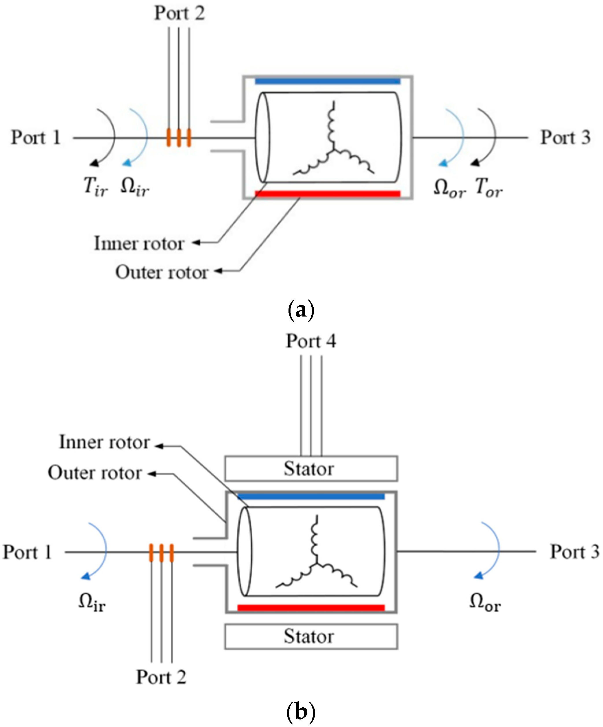
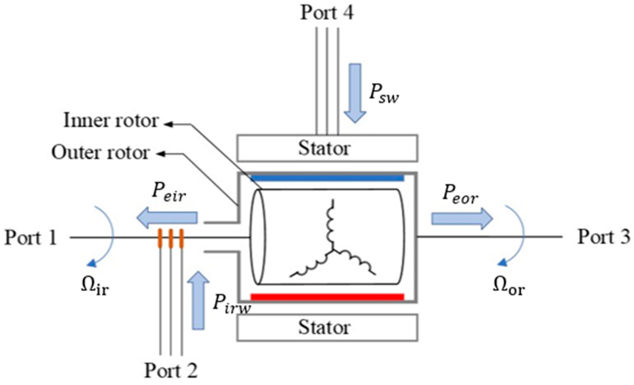
One solution is to use a dual-mechanical-port (DMP) generator. Unlike conventional electric machines, which feature one stator and one rotor, DMP machines have two rotors and do not necessarily have a stator. In 1994, M. Ehsani and S. Sodhi, at Texas A&M University, introduced a DMP machine consisting of only two rotors, named the “transmotor” [13]. It is also called a two-member transmotor. The diagram of a transmotor is shown in Figure 2a. Note that the red and blue bars in the inner rotor represent a permanent magnet’s north and south poles, respectively (the same applies to all the machine figures with a permanent magnet rotor). A transmotor signifies the active electromagnetic coupling of the two rotors, enabling mechanical power transfer directly between the two mechanical ports (Port 1 and Port 3) and the inner and outer rotor shafts, and the amount of the transferred mechanical power is decided by the electrical port (Port 2) and inner rotor windings [13]. This structural innovation aims to enhance energy transfer efficiency. M. Ehsani also proposed a three-member transmotor variation, as shown in Figure 2b. The three-member topology has a stator in addition to the two rotors, which provides more control degrees of freedom than the two-member topology, but its control becomes more complicated. Later, L. Xu, at Ohio State University, furthered the research on DMP machines and mainly focused on the three-member topology [14,15]. DMP machines have garnered more attention in recent years [16,17,18].
Transmotors have possible applications in electric vehicles (EVs) and hybrid electric vehicles (HEVs), as they could be used to improve the overall performance of the vehicles [19,20,21,22,23]. Papers [21,22,23] by M. Ehsani, NF. Ershad, and RT. Mehrjardi explored different applications of transmotors in EVs or HEVs. Although the applications vary, the fundamental idea in these papers is to combine a two-member transmotor with a flywheel as a kinetic energy recovery system (KERS) to increase the compactness and efficiency of the powertrains. Additionally, the flywheel plays a role in alleviating the burden on the vehicle battery by efficiently storing and recovering kinetic energy during deceleration and braking, making the overall vehicle more energy-efficient and sustainable. DMP machines are rarely considered for wind power generation. In papers [24,25], a three-member DMP generator was used as a variable gearbox with a battery energy storage unit, and a second generator was required to connect to the power grid.
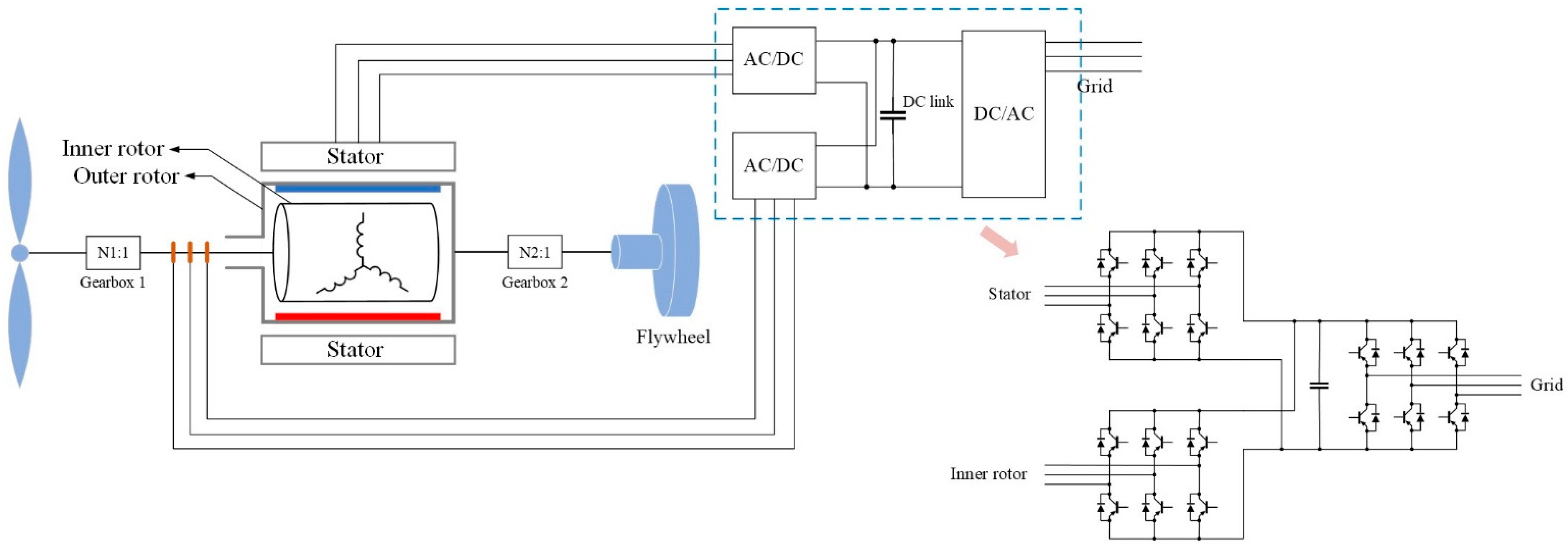
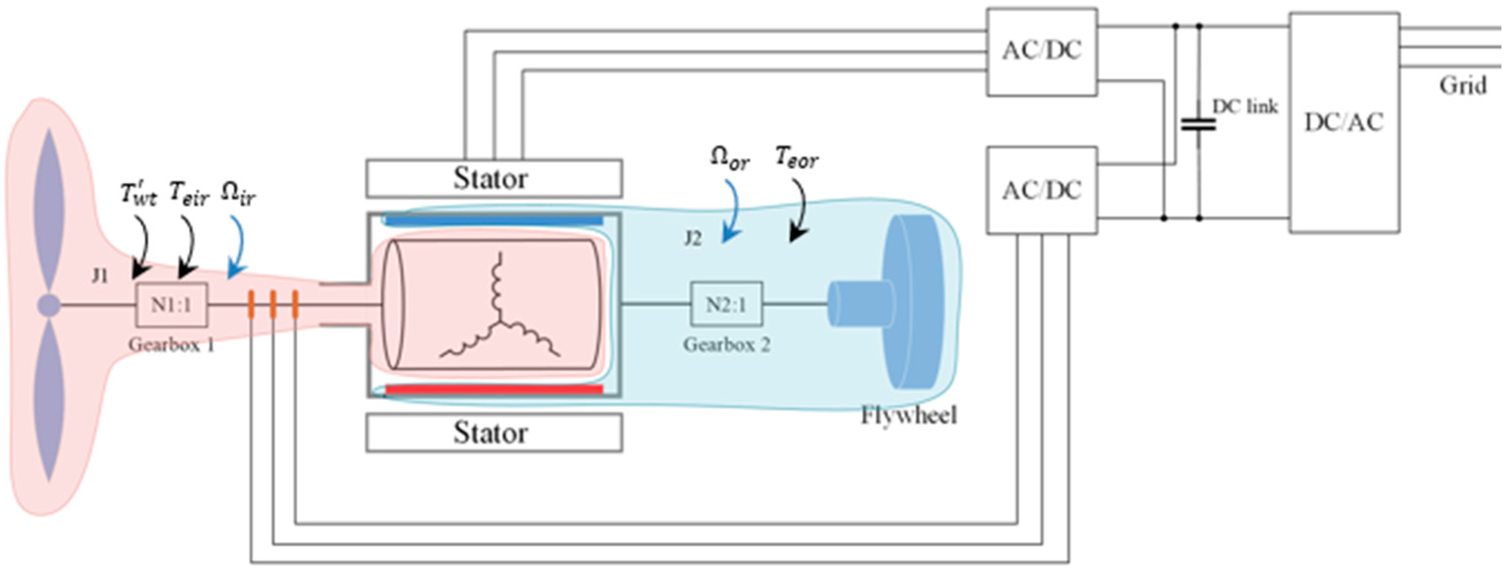
This paper proposes a “Three-member transgenerator–flywheel” system. Its configuration is shown in Figure 3, in which the wound inner rotor is driven by the wind turbine, the permanent magnet (PM) outer rotor is connected to the flywheel, and the wound stator provides more control degrees of freedom and serves the critical function of achieving independent control of the two rotors for different purposes. This configuration offers several advantages:
(1)
Compactness: The proposed configuration integrates the wind turbine and flywheel in one system, eliminating the drive motor and converters, making it possible to fit it into a turbine nacelle.
(2)
Efficiency: The connection between the wind turbine and the flywheel, using the proposed configuration, creates a shorter path with fewer electrical components for power transfer, which reduces the total power losses and thus increases the overall power efficiency.
(3)
Scalability: This configuration ensures one transgenerator is equipped with one flywheel in the wind turbine. The one-to-one feature enables a wind farm to achieve substantial energy storage when the wind turbine number is significant.
(4)
Distribution: The one-to-one feature ensures flywheels are as distributed as the wind turbine units. This feature becomes more evident in a wind-based distributed generation (DG) system.

2. Three-Member Transgenerator

2.1. Mathematical Model

2.1.1. Flux Linkage and Voltage Equations

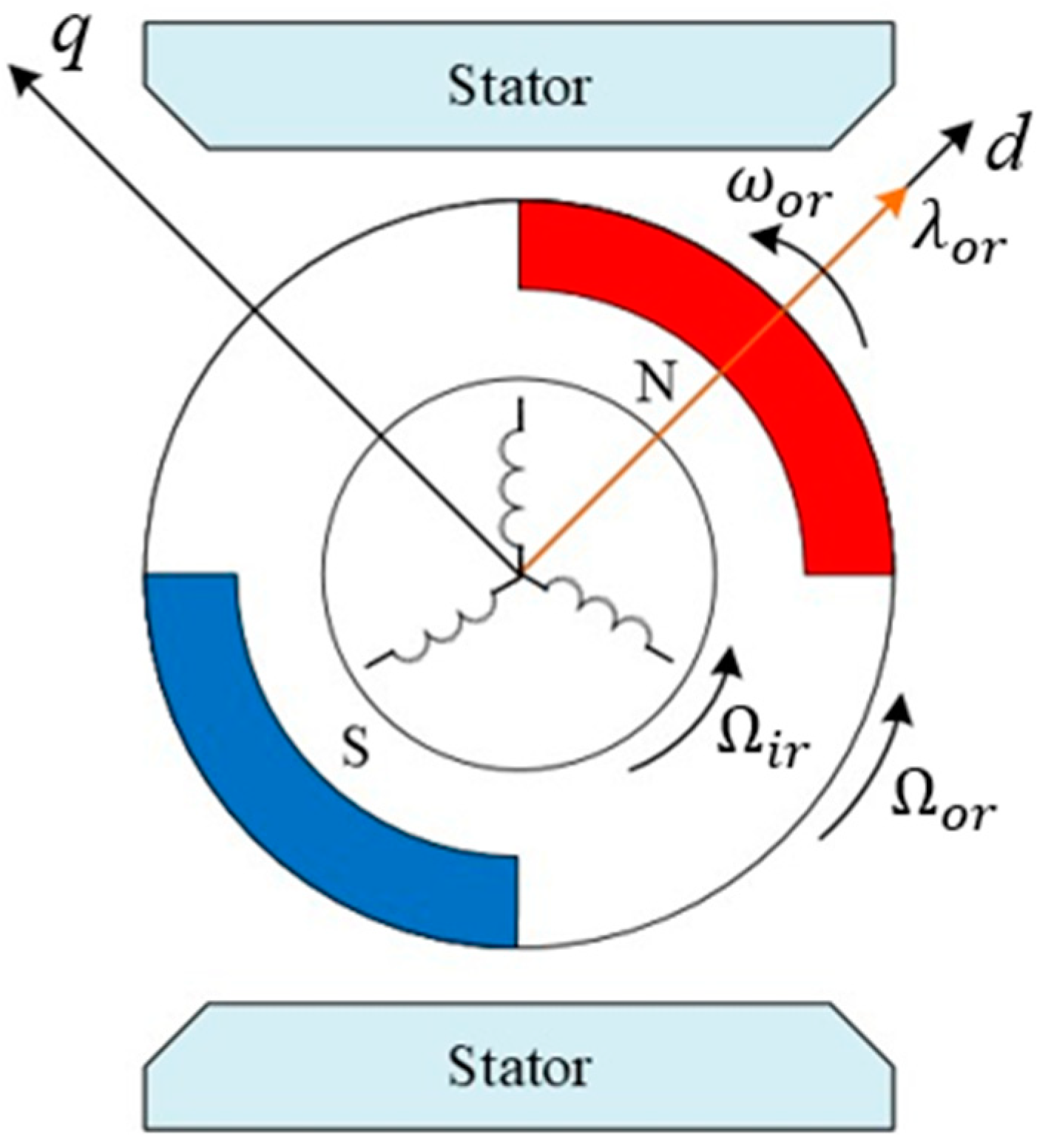
Define the d-axis aligned with the space vector of the PM rotor flux, λ o r . The d-q reference frame is shown in Figure 4. Then, the flux linkage equations are expressed as follows:
λ d s = L d s i d s + L m i d i r + λ o r λ q s = L q s i q s + L m i q i r λ d i r = L d i r i d i r + L m i d s + λ o r λ q i r = L q i r i q i r + L m i q s
where L m is the mutual inductance between the stator and inner rotor windings, and L σ s and L σ i r are the leakage inductances of the stator and inner rotor. Self-inductance can be defined as follows: L d s = L σ s + L m , L q s = L σ s + L m , L d i r = L σ i r + L m , L q i r = L σ i r + L m . Thus, L d s = L q s and L d i r = L q i r .
Define the angular frequencies of the inner and outer rotors as ω i r and ω o r . Then, the stator angular frequency is ω o r , since the stator is fixed (no rotation), and the inner rotor slip angular frequency is ( ω o r ω i r ) . The voltage equations for the stator and inner rotor are as follows:
v d s = R s i d s ω o r λ q s + d λ d s d t v q s = R s i q s + ω o r λ d s + d λ q s d t v d i r = R i r i d i r ω o r ω i r λ q i r + d λ d i r d t v q i r = R i r i q i r + ω o r ω i r λ d i r + d λ q i r d t
where v , i , R , λ , and ω are voltage, current, resistance, flux linkage, and angular velocity, respectively; subscripts d and q mean d , q components, respectively; and subscripts i r , o r , and s mean inner rotor, outer rotor, and stator, respectively.

2.1.2. Power and Torque Equations

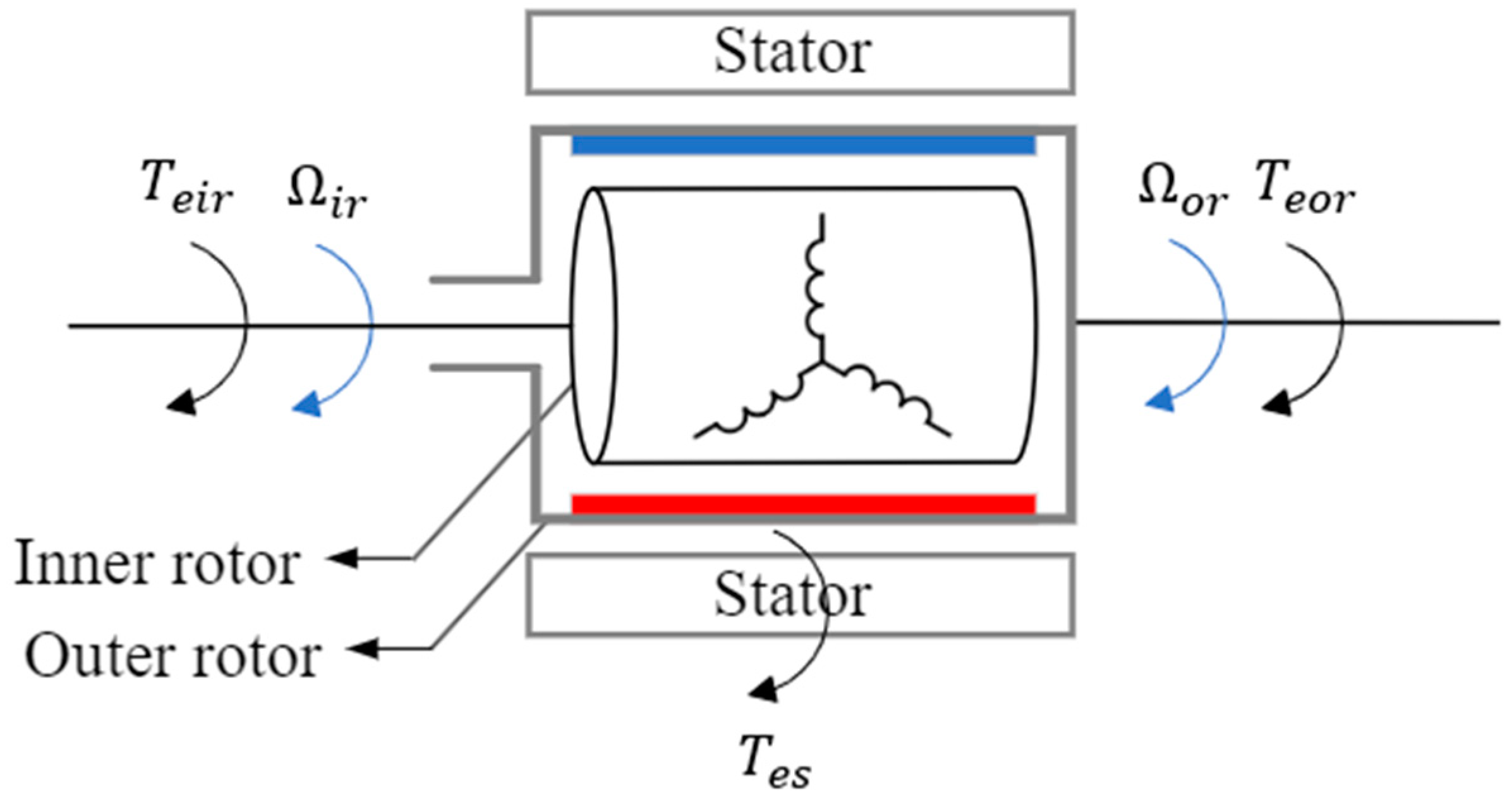
A torque analysis diagram of the transgenerator is shown in Figure 5. The electromagnetic torque on the outer rotor, T e o r , is the sum of two parts: one is from the stator, and the other is from the inner rotor due to the interaction between the magnetic fields produced by the current in the windings. The same analysis method applies to the electromagnetic torques on the inner rotor and stator, T e i r and T e s , as illustrated in (3)–(5). Note that for the interactive torques, the subscript in the front is the torque-receiving object, and the subscript in the back is the torque-exerting object, e.g., T o r i r means the torque on the outer rotor exerted by the inner rotor.
T e s = T s o r + T s i r
T e i r = T i r s + T i r o r
T e o r = T o r i r + T o r s
Using (3)–(5), Figure 4 can be simplified to Figure 6.
Define the angular velocities of the inner and outer rotors as Ω i r and Ω o r . With Figure 6, the mechanical power of the inner and outer rotors, P e i r and P e o r , due to the electromagnetic torques, T e i r and T e o r , can be calculated as follows:
P e i r = T e i r Ω i r
P e o r = T e o r Ω o r
The total electrical power in the three-phase windings of the stator and inner rotor can be calculated as the dot product of the transpose voltage matrix, V a b c t , and the current matrix, i a b c [26]. Note that the bold variables represent matrices.
P e l e c = v a b c s t · i a b c s + v a b c i r t · i a b c i r
Applying Park transformation to (8) yields the electrical power expression under the d-q frame:
P e l e c = 3 2 v d q s t · i d q s + v d q i r t · i d q i r
Expanding (9) by substituting (2) into it, the expressions for P e i r and P e o r can be obtained in terms of the flux linkages and currents:
P e i r = 3 2 ω i r λ q i r i d i r λ d i r i q i r
P e o r = 3 2 ω o r λ d s i q s λ q s i d s + 3 2 ω o r λ d i r i q i r λ q i r i d i r
When the number of rotor pole pairs is p , the rotors’ angular frequencies, ω , and angular velocities, Ω , have the following relations:
ω i r = p Ω i r
ω o r = p Ω o r
The electromagnetic torques on the inner and outer rotors can be derived from (14) and (15) by substituting (6) and (12) into (10), and (7) and (13) into (11), respectively:
T e i r = 3 2 p λ q i r i d i r λ d i r i q i r
T e o r = 3 2 p λ q s i d s λ d s i q s + 3 2 p λ q i r i d i r λ d i r i q i r
According to Newton’s third law of motion, for two objects that exist in mutual interaction, the torque exerted on each object by the other is equal in magnitude and opposite in direction. Applying this law to the transgenerator yields T s o r = T o r s , T i r s = T s i r , and T o r i r = T i r o r . Using these relations, add (3) and (4):
T e s + T e i r = T s o r + T i r o r = T o r s + T o r i r
Observing (16) and (5) yields:
T e o r = T e s + T e i r
By observing (14), (15), and (17), the stator torque expression can be obtained as:
T e s = 3 2 p λ q s i d s λ d s i q s
By substituting (1) into (14) and (18), the torque expressions of the inner rotor and stator can be rewritten as:
T e i r = 3 2 p L q i r L d i r i d i r i q i r + L m i q s i d i r L m i d s i q i r λ o r i q i r
T e s = 3 2 p L q s L d s i d s i q s + L m i d s i q i r L m i q s i d i r λ o r i q s
With L q s = L d s and L q i r = L d i r , (19) and (20) are simplified to (21) and (22), respectively:
T e i r = 3 2 p L m i q s i d i r L m i d s i q i r λ o r i q i r
T e s = 3 2 p L m i d s i q i r L m i q s i d i r λ o r i q s
Substituting (21) and (22) into (17) yields:
T e o r = 3 2 p λ o r i q s + i q i r
From (23), the electromagnetic torque on the outer rotor is only related to the q components of the currents in the stator and inner rotor windings since p and λ o r are constants.

2.2. Power Flow

The proposed three-member machine is a four-port machine with two mechanical ports (the inner and outer rotors) and two electrical ports (shafts of the inner and outer rotors). A power flow diagram of the three-member machine is illustrated in Figure 7, where P e i r and P e o r are the mechanical power (due to the electromagnetic torques) delivered by the inner rotor and outer rotor, and P i r w and P s w are the electrical power (due to the electromagnetic induction) received by the windings of the inner rotor and stator.
Let P m e c be the total mechanical power delivered by the two rotors, which equals the sum of P e o r and P e i r , as expressed in (24):
P m e c = P e o r + P e i r = T e o r Ω o r + T e i r Ω i r
The total electrical power received by the windings, P e l e c , equals the sum of electrical power in the inner rotor and stator windings, P i r w and P s w , as expressed in (25):
P e l e c = P i r w + P s w
When the losses (such as copper and iron losses) are ignored, the total power injected into the machine at each moment is zero, as expressed in (26):
P e o r + P e i r P i r w + P s w = 0
That is,
P m e c = P e l e c
Since the power flow at each port is bidirectional, there are many permutations for the power flow directions. Based on Figure 7, the power flow of the three-member machine can be obtained as follows when all the losses are ignored:
(1)
The electrical power received by the machine, P e l e c , equals the mechanical power delivered by the machine, P m e c , at each moment.
(2)
When P e l e c ( P m e c ) > 0 , the machine receives electrical power and delivers mechanical power; the machine operates as a transmotor.
(3)
When P e l e c ( P m e c ) < 0 , the machine delivers electrical power and receives mechanical power; the machine operates as a transgenerator.

3. Flywheel

3.1. Mechanical System Overview

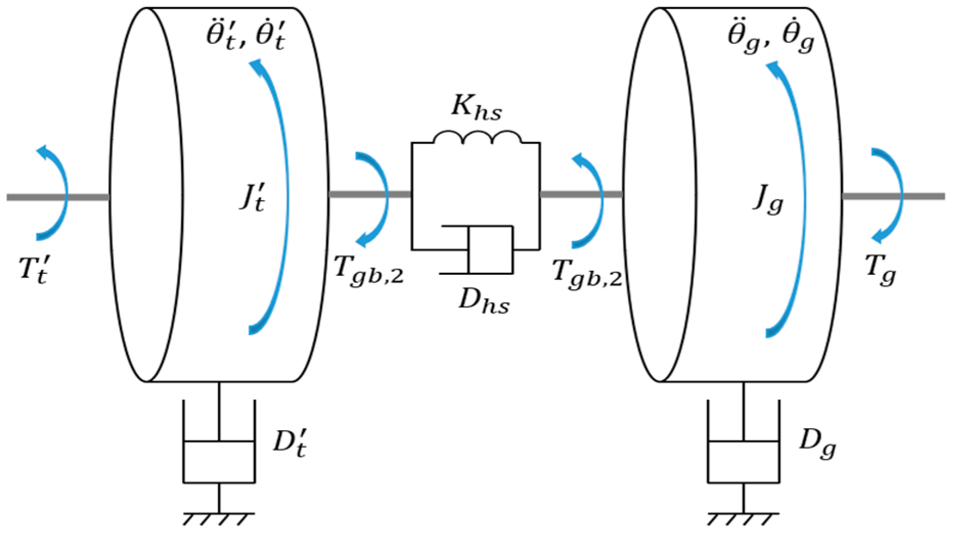
The mechanical model of the transgenerator–flywheel system consists of a two-mass drivetrain model [27], in which two rotating masses are connected through a shaft, as shown in Figure 8. The internal torque is due to the deformation of the connecting shaft, and any material will undergo some degree of deformation. The speed difference of the two masses depends on the flexibility of the shaft. The transgenerator–flywheel system is a dual two-mass drivetrain model, as shown in Figure 9, wherein the wind turbine-inner rotor and outer rotor-flywheel are marked in red and blue, respectively; the wind turbine-inner rotor is marked as system 1; and the outer rotor-flywheel is marked as system 2. To simplify the model, the connecting shafts in each system are considered rigid bodies, and all mechanical losses are ignored. Note that each system has a gearbox, and the model analysis is referred to the rotor side. The model is based on the following assumptions:
(1)
The total inertia of each system equals the sum inertia of each component referred to the rotor sides; the total inertia of system 1 and system 2 are J 1 and J 2 , respectively.
(2)
The rotational speed of system 1 is consistent with the inner rotor’s angular velocity, Ω i r ; the speed of system 2 is consistent with the outer rotor’s angular velocity, Ω o r .
(3)
The torques on system 1 include torque on the wind turbine referred to the inner rotor side, T w t , and the electromagnetic torque on the inner rotor, T e i r ; the torque on system 2 is the electromagnetic torque on the outer rotor, T e o r .

3.2. Flywheel Charging Power and Storage Energy

With the simplified mechanical model in Figure 9, the charging power of the flywheel, P f w , equal to the mechanical power of the outer rotor, P e o r , can be calculated as the product of the outer rotor torque and angular velocity (speed):
P f w = P e o r = T e o r Ω o r
Based on the torque and speed directions in Figure 9, when the power, P f w , is positive, the flywheel receives power from the transgenerator, and the flywheel is charged; when the power is negative, the flywheel delivers power to the transgenerator, and the flywheel is discharged.
The energy stored in the flywheel can be calculated with the flywheel inertia (referred to the rotor side) and the outer rotor speed:
E f w = 1 2 J f w Ω o r 2
where J f w is the flywheel inertia referred to the rotor side, which has the following relationship with the actual flywheel inertia, J f w , and the gearbox ratio between the outer rotor and flywheel, N 2 .
J f w = J f w N 2 2
The actual flywheel speed, Ω f w , can be calculated with the outer rotor speed and the gearbox ratio, N 2 :
Ω f w = Ω o r N 2
With the actual flywheel speed obtained, the energy stored in the flywheel can also be expressed with the actual flywheel inertia and speed:
E f w = 1 2 J f w Ω f w 2
If the maximum speed of the flywheel is Ω f w , m a x , the storage capacity of the flywheel is:
E f w , c a p a c i t y = 1 2 J f w Ω f w , max 2
If the flywheel decelerates from a higher speed, Ω f w 2 , to a lower speed, Ω f w 1 , the energy released from the flywheel, Δ E f w , is:
Δ E f w = 1 2 J f w Ω f w 2 2 Ω f w 1 2

3.3. Flywheel Power Management Strategies

According to (28), flywheel power can be managed by changing the outer rotor torque, outer rotor speed, or both. The analysis is as follows:
(1)
Due to the acceleration, the speed change in the flywheel cannot be furnished immediately, delaying the power response to the demand. Therefore, changing the outer rotor torque is a better strategy.
(2)
To ensure the accuracy of the power control by controlling the outer rotor torque, the speed should change slightly, which requires the flywheel inertia referred to the outer rotor side to be significant.
(3)
Before the flywheel power management process, the flywheel should be accelerated to a state of charge (SOC) to ensure that the flywheel can release enough energy during emergencies. Additionally, there should be a margin with the maximum storage to leave enough space for charging. The preset flywheel SOC in this paper is 80%, and then the flywheel speed will fluctuate (slightly, most of the time) at around 80% SOC, as shown in Figure 10.
(4)
The performance of the flywheel power response depends on the performance of the outer rotor torque control, which will be introduced later.

3.4. Flywheel Selection

3.4.1. Shape

The flywheels typically take disc or ring shapes, so the flywheel selection process discussed in this paper focuses on these two shapes. As shown in Table 1, the inertia of the ring-shaped flywheel is greater than that of the disc flywheel when they have the same mass and radius ( r = r 2 ). To achieve the same mass, when the radius of the disc-shaped flywheel equals the outer radius of the ring-shaped flywheel ( r = r 2 ) and they have the same material density, ρ is the same, and the mass and volume have the following relation:
m = ρ V
This means their volumes should be equal. The volume of the disc flywheel, V d i s c , and the ring flywheel, V r i n g , are calculated as follows:
V d i s c = π r 2 · h d i s c
V r i n g = π r 2 2 r 1 2 · h r i n g
where h d i s c and h r i n g are the thicknesses of the disc and ring flywheels, respectively. Since r = r 2 , r 2 > r 2 2 r 1 2 when V d i s c = V r i n g , h d i s c < h r i n g . This means that when the volumes are equal, the ring-shaped flywheel is thicker than the disc-shaped flywheel if they have the same radius and material density. However, according to the calculation, the effect of thickness on the nacelle horizontal space is ignorable. Thus, the ring-shaped flywheel is selected.

3.4.2. Material

For the flywheel described in this paper, we decided on steel for the following reasons. First, the high density of steel (7850 kg/m3) helps reduce the flywheel size compared to lower-density materials. Second, steel has a strong tensile strength (around 70,000 psi and a decent yield strength (around 50,000 psi), which allows the flywheel to withstand high-speed rotation. The chart of strength in [28] shows the strength of different materials. Further, the steel prices are not expensive compared to many other materials, which means steel is cost-effective. A chart of prices showing the prices of different materials is available in [29].

4. Control System

The control system consists of rotor-side and grid-side control based on field-oriented control (FOC) [30]. The control details are not illustrated in this paper.

4.1. Rotor-Side Control

The goal of rotor-side control is to control each rotor independently to achieve speed control on the inner rotor side and torque control on the outer rotor side for different purposes.

4.1.1. Inner Rotor Speed Control

The inner rotor control aims to achieve maximum power point tracking (MPPT). The MPPT control applies indirect torque control [24], as shown in Figure 11. Note that the * sign represents reference (same for the rest). The MPPT algorithm is the higher-level control, producing the speed reference for the lower-level control.

4.1.2. Outer Rotor Torque Control

As illustrated in Section 3.3, the purpose of the outer rotor-side control is to manage the flywheel charging/discharging power by controlling the outer rotor torque. The outer rotor control scheme is shown in Figure 12, in which the flywheel energy storage (FES) management algorithm is the higher-level control, producing the torque control reference for the lower-level control.

4.1.3. Rotor-Side Control Diagram

Figure 13 shows the rotor-side control diagram, in which the FES and MPPT algorithm modules generate control references for inner rotor speed control and outer torque control for the outer control loops, respectively (as introduced in Section 4.1.1 and Section 4.1.2). The inner control loops are current control.

4.2. Grid-Side Control

The purpose of the grid-side control is to maintain the DC link voltage constant and control the reactive power from the grid-side converter to the grid. In the grid-side control, the space vector sum of the grid voltage, v g , is aligned with the d-axis (a different d-q axis from the rotor-side control). The grid-side control diagram is shown in Figure 14.

5. Simulation and Verification

5.1. Simulink Modeling

System modeling can be carried out in MATLAB 2023b/Simulink. The modeling includes the wind turbine, transgenerator–flywheel system, and control system.
The wind turbine model generates the torque on the wind turbine, T w t , from the wind power. Its modeling is based on the wind turbine aerodynamic model. Assume a fluid of wind flow enters the wind turbine blades with a wind speed of V w , the swept area of the blades is A , and the air density is ρ ( ρ = 1.225   k g / m 3 ). Then, the power contained in the wind flow, P w , is calculated as:
P w = 1 2 ρ A V w 3
where A = π R 2 , with serving as R the radius of the swept area or blade length.
The electrical power captured from the wind power, P w t (or P t ), equals the product of P w and a power coefficient, C P :
P t = 1 2 ρ π R 2 V w 3 C P
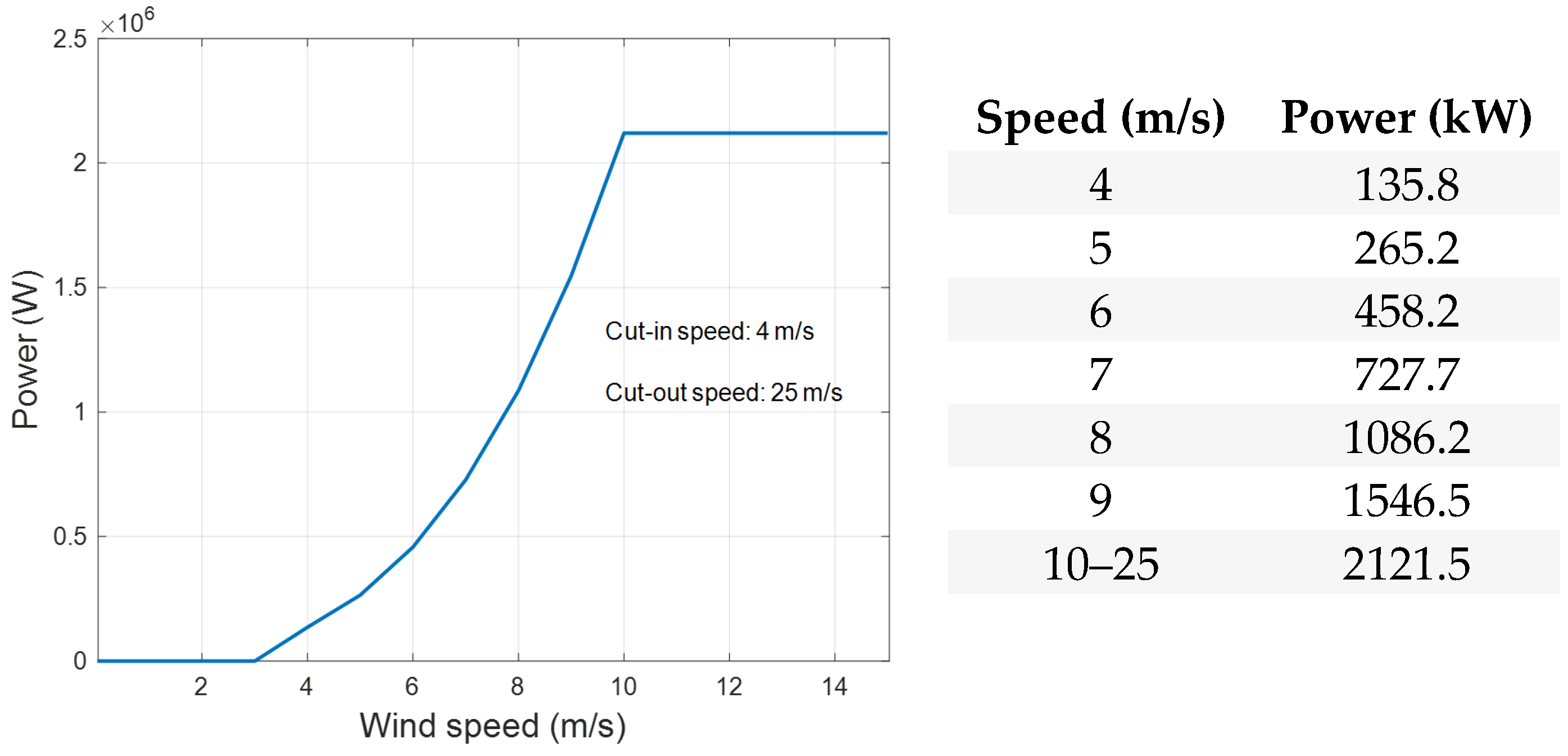
The power curve of the wind turbine is shown in Figure 15.
C p is a function of the tip speed ratio, λ , and the pitch angle, β , i.e., C p ( λ , β ) . The speed ratio λ is defined by the ratio of the blade speed ( R Ω t ) to wind speed:
λ = R Ω t V w
where Ω t is the angular velocity of the wind turbine.
One expression of C p ( λ , β ) is commonly used to adjust different turbines [31]:
C P λ i , β = k 1 k 2 λ i k 3 β k 4 β k 5 k 6 e k 7 / λ i
where
λ i = 1 λ + k 8
k 1 ~ k 8 are adjustable coefficients. β is set to 0 in this paper.
The torque of the turbine, T w t (or T t ), is calculated as follows:
T t = P t Ω t = 1 2 ρ π R 3 V w 2 C t
where C t is the torque coefficient, and the relationship between C t and C P is as follows:
C P = λ C t
The wind turbine parameters are shown in Table 2.
Transgenerator–flywheel modeling: The electrical part modeling of the transgenerator is based on the flux linkage and voltage equations in (1) and (2). The parameters of the electrical system are shown in Table 3. The mechanical part modeling is based on the simplified dual two-mass drivetrain model in Figure 9. The parameters of the mechanical system are shown in Table 4, in which all the components are referred to the rotor side. The flywheel modeling is based on the flywheel selection process discussed in Section 3.4. The flywheel parameters are shown in Table 5.
Control system modeling is based on the control diagrams in Figure 13 and Figure 14 for rotor-side control and grid-side control, respectively.

5.2. Control System Verification

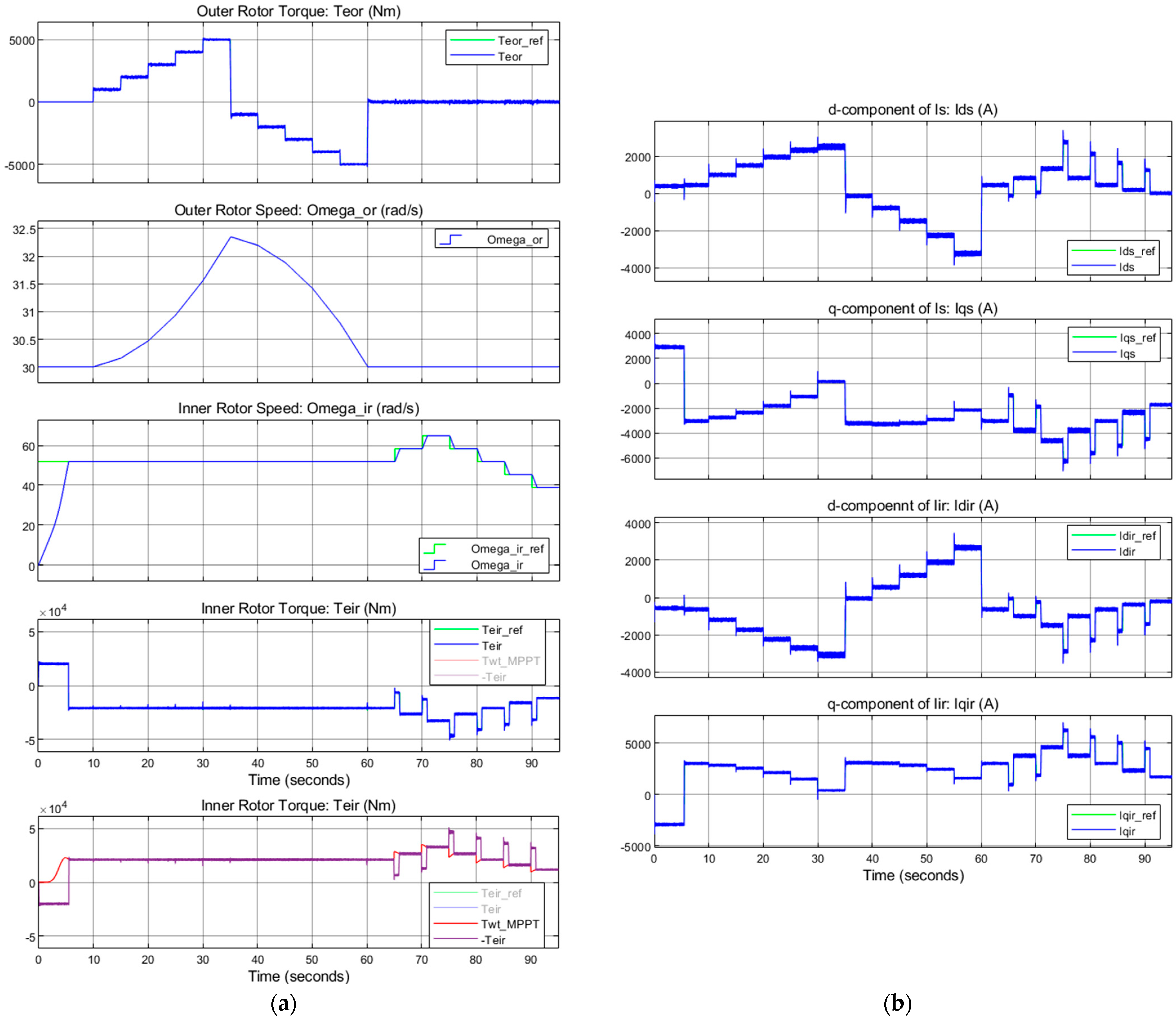
This section aims to evaluate the control accuracy and time response. The simulation duration is 95 s; a simulation duration of 0–65 s is found for the outer rotor torque control verification, while a duration of 65–95 s is found for the inner rotor speed control verification, and grid-side control verification occurs throughout the simulation.

5.2.1. Set Up

  • Outer rotor torque control
Verification: Set a series of constant torque references for the outer rotor and observe the actual torque response (outer control loop) and corresponding currents response (inner control loops). Also, ensure the outer rotor speed changes with torque correctly. Note that the outer rotor torque limit range is −5300 N· to 5300 N·. Meanwhile, the wind speed of 8 m/s for the wind turbine and the MPPT unit is set to generate corresponding constant wind turbine torque and an inner rotor speed reference during the outer rotor torque control verification.
(1)
0–10 s: The inner rotor accelerates to a constant speed, and the outer rotor torque is set to zero (turbine start-up). The initial speed of the outer rotor is 30 rad/s.
(2)
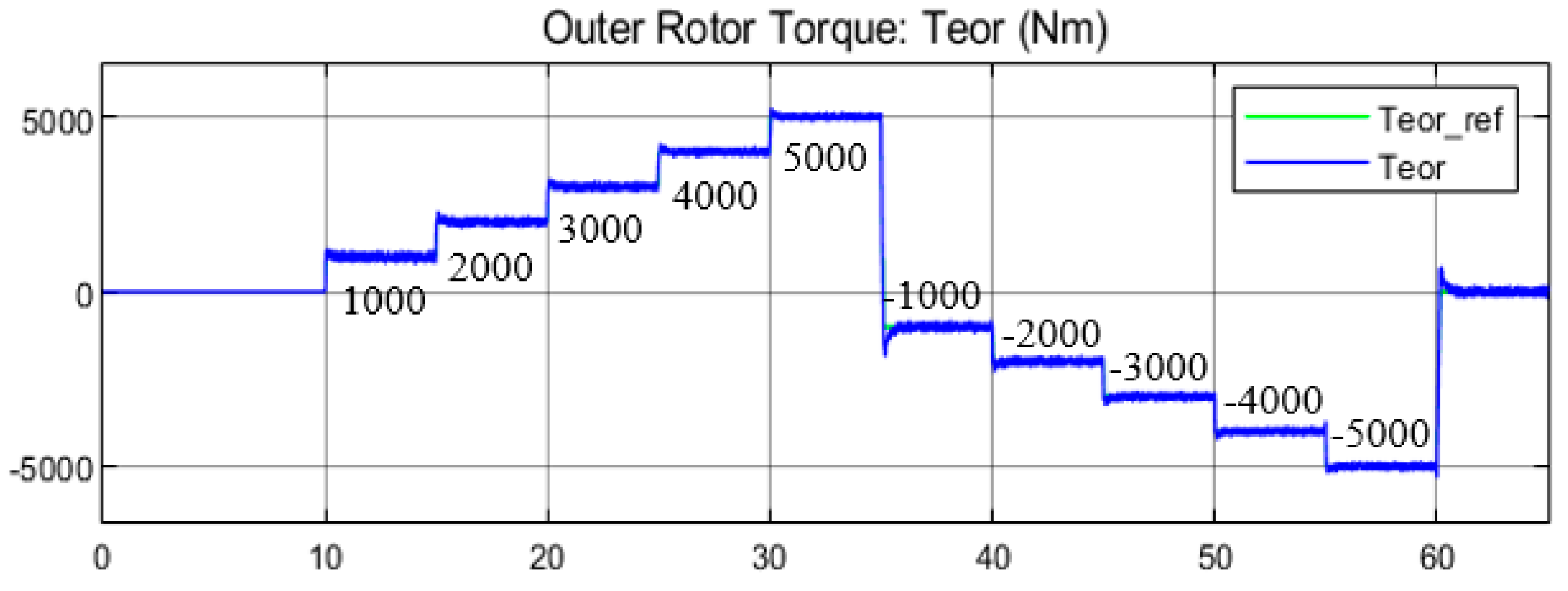
10–65 s: The outer rotor torque reference is set every 5 s, and the values are 1000 N·m, 2000 N·m, 3000 N·m, 4000 N·m, 5000 N·m −1000 N·m, −2000 N·m, −3000 N·m, −4000 N·m, −5000 N·m, and 0.
  • Inner rotor speed control
Verification: Set a series of constant wind speeds for the wind turbine and the MPPT unit to generate a series of corresponding wind turbine torques and inner rotor speed references. Observe the actual speed response (outer control loop), corresponding torque response, and current response (inner control loops). From 65 to 95 s, the wind speed is set every 5 s, and the values are 9 m/s, 10 m/s, 9 m/s, 8 m/s, 7 m/s, and 6 m/s.
  • Grid-side control
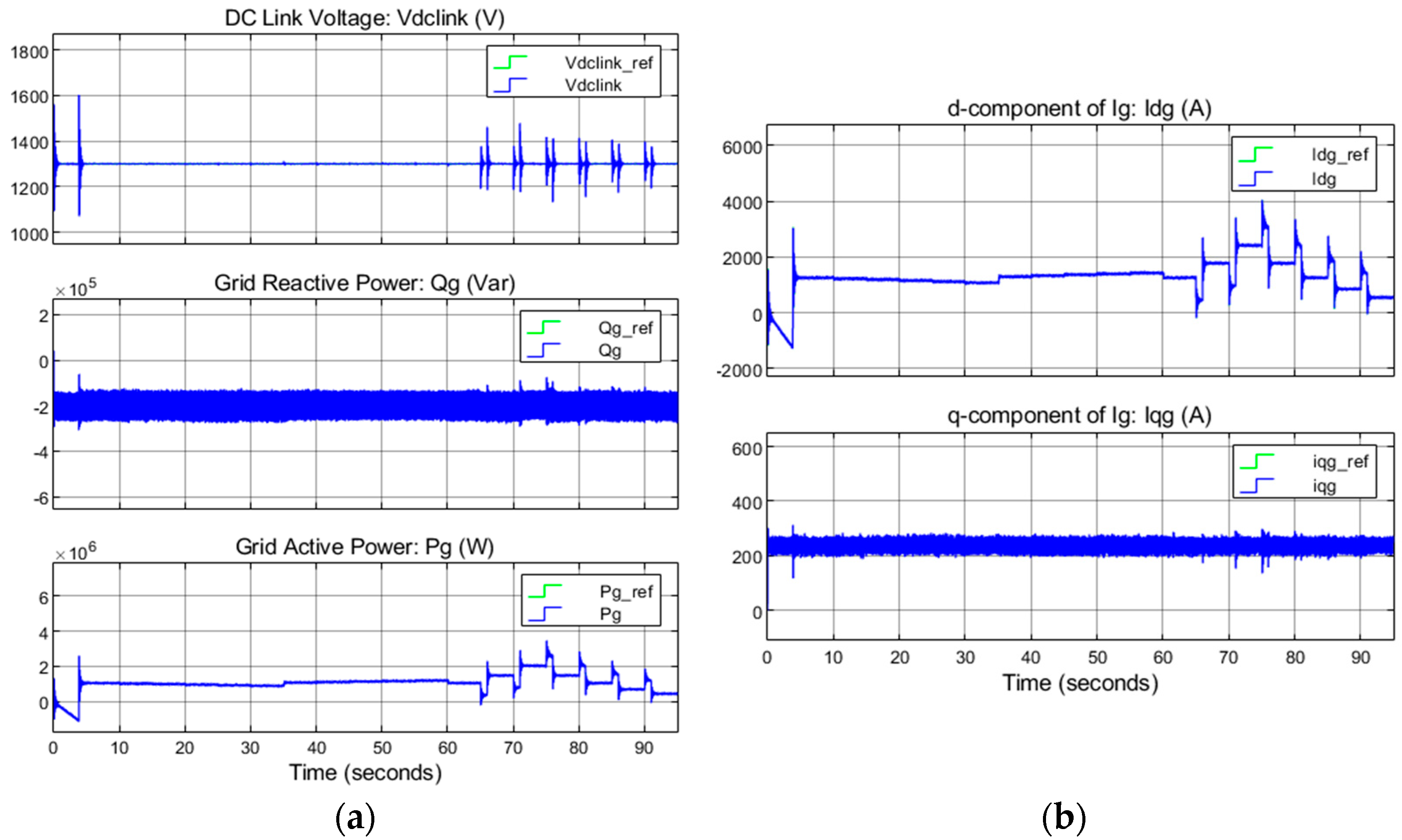
Verification: Set the DC link voltage reference to 1300 V and the grid reactive power reference to −200 kVar. Observe the actual voltage and reactive power response (outer control loops), active power response, and current response (inner control loops).

5.2.2. Results

  • Outer rotor torque control
The outer rotor torque control results from 0 to 65 s are shown in Figure 16a (the top two subfigures) and Figure 16b. Note that the blue lines represent the actual values, and the green lines represent the control references. As shown in Figure 16a, as the torque reference changes, the actual torque can quickly track the reference (around 1 s) (the blue and green lines overlap), with a slight overshoot. The outer rotor accelerates/decelerates with correct accelerations as the torque changes. Meanwhile, the d-q components of the stator and inner rotor currents track the current references promptly, as shown in Figure 16b (0–65 s). Thus, the outer rotor control is verified.
  • Inner rotor speed control
The inner rotor speed control results are shown in Figure 16a (the third to fifth subfigures) and Figure 16b from 65 to 95 s. Figure 16a shows that the speed can converge to the reference within 1.2 s. The actual inner rotor torque tracks the torque reference generated by the speed controller. The inner rotor acceleration is determined by T w t _ M P P T and the inner rotor torque (the fifth subfigure). Meanwhile, the d-q components of the stator and inner rotor currents track the current references promptly, as shown in Figure 16b (65–95 s). Thus, the inner rotor control is verified.
  • Three-phase currents and voltage on the rotor side
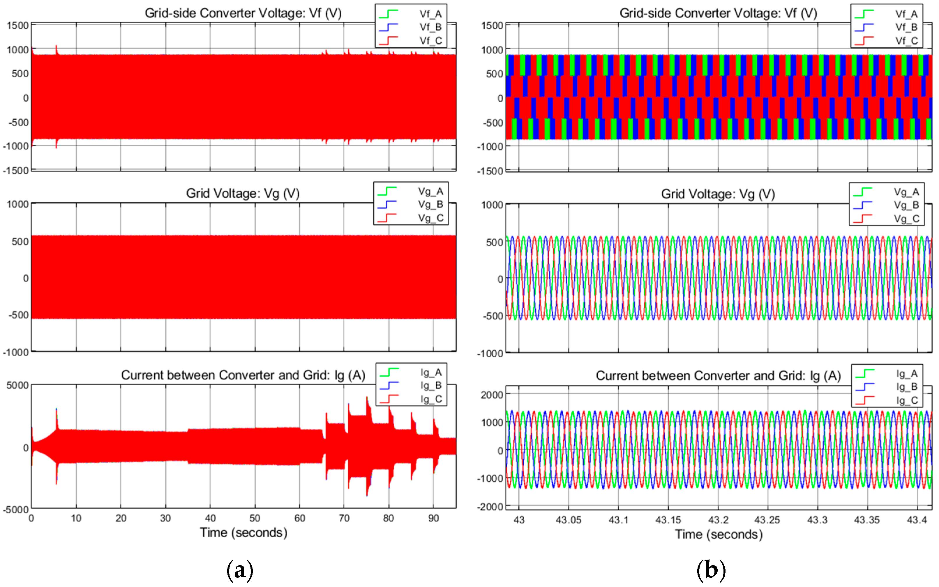
Figure 17 shows the waveforms of the stator and inner rotor’s three-phase voltages and currents. The voltages are square waves from the converter sides, and the currents are sine waves. The frequencies in the stator and inner rotor windings match the corresponding slip angular velocities and angular frequencies.
  • Grid-side control
The grid-side control results are shown in Figure 18. From Figure 18a, the DC link voltage and the grid reactive power keep track of their references during the simulation. The actual active power on the grid side tracks the active power reference. Meanwhile, the d-q current components track the current reference with a timely response, as shown in Figure 18b. The change in the active power is closely related to the reference value change on the generator (rotors) side, mainly the inner rotor (wind turbine). Thus, the grid-side control is verified.
  • Three-phase current and voltage on the grid side
Figure 19 shows the waveforms of the grid-side three-phase voltages and currents. The voltages on the converter side are square waves, while the voltages on the grid side and the currents are sine waves with a frequency of 60 Hz.

5.3. Flywheel Performance Evaluation

Section 3.3 introduces the flywheel power management strategies, and the flywheel parameters are shown in Table 5. Table 6 shows the flywheel performance parameters.

5.3.1. Set Up

The simulation duration is 65 s. The initial speed of the outer rotor is set to 100 rad/s (80% SOC). A duration of 0–10 s is required for the wind turbine start-up process under a wind speed of 8 m/s. A duration of 10–65 s is required for flywheel charging/discharging. To simplify the FES management unit, we set a series of outer rotor torque reference values every 5 s, and the values are 1000 N·m, 2000 N·m, 3000 N·m, 4000 N·m, 5000 N·m −1000 N·m, −2000 N·m, −3000 N·m, −4000 N·m, −5000 N·m, and 0, as shown in Figure 20. Observe the power response of the flywheel.

5.3.2. Results

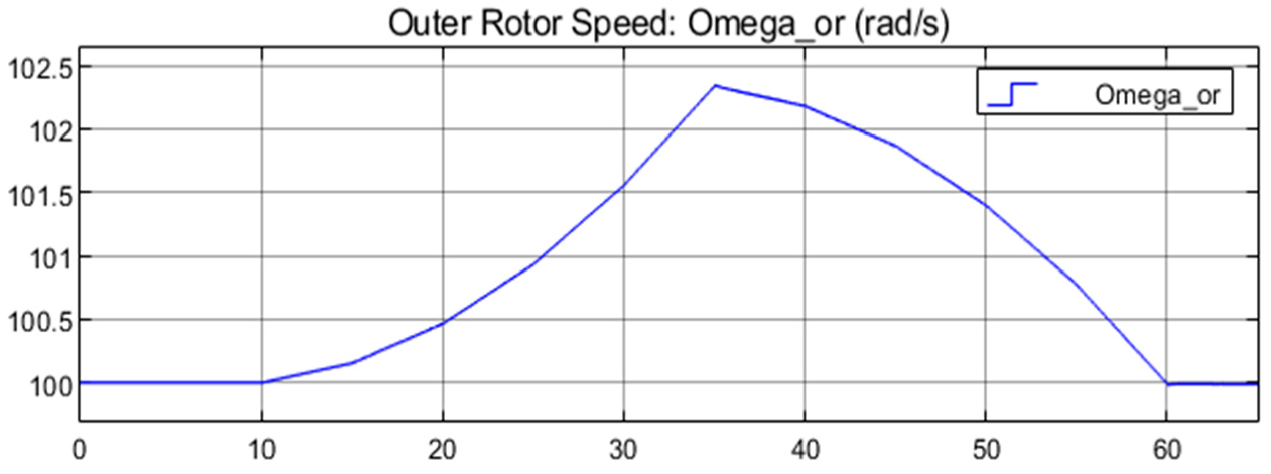
Figure 21 shows the outer rotor speed, and the power plots are shown in Figure 22. Note that the power flow directions in the modeling are consistent with those in Figure 7.
(1)
0–10 s: after the inner rotor start-up process, the power generated by the wind turbine is 1.09 MW, as shown in the first plot of Figure 22; the power delivered by the inner rotor is −1.08 MW, meaning the inner rotor receives 1.08 MW of power from the wind turbine, as shown in the second plot in Figure 22.
(2)
10–35 s: the outer rotor accelerates (flywheel) in a series of increasing positive accelerations, and the flywheel is charged, as shown in the third plot in Figure 22.
(3)
35–60 s: the outer rotor (flywheel) decelerates in a series of increasing negative accelerations, and the flywheel is discharged, as shown in the third plot in Figure 22.
(4)
60–65 s: the acceleration of the outer rotor is 0, and the flywheel is neither charged nor discharged, as shown in the third plot in Figure 22.
(5)
10–65 s: the total electrical power received by the transgenerator is negative (the power generated by the transgenerator is positive), and it changes with the flywheel charging power in real time, as shown in the fourth plot in Figure 22.
The third power plot in Figure 22 also indicates that the flywheel responds quickly to the outer rotor torque command (reference) and delivers accurate power. The maximum power at 80% is slightly higher than 510 kW (since the outer torque limit is 5300 N·m but the maximum power in the simulation is 5000 N·m), about 27% of the wind turbine’s rated power. The torque direction decides the power flow direction. In addition, the torque has little effect on the flywheel speed due to its significant inertia (referred to the outer rotor side). Hence, the charging power changes slightly for a specific torque command, as shown in Figure 21, ensuring the accuracy of flywheel power delivery. Overall, the flywheel performs as expected.

6. Conclusions and Future Work

This paper presents a three-member transgenerator–flywheel system for wind power generation, which is a new flywheel energy storage (FES) concept that posits that the flywheel can be directly integrated with the wind turbine using a dual-mechanical-port (DMP) generator (transgenerator). This configuration makes the FES more modular and distributed than the conventional FES system. The system was illustrated by transgenerator (presented from the mathematical model and power flow), flywheel (presented from the principle, power characteristics in the transgenerator–flywheel system, energy management strategies, and flywheel selection considerations), and a control system. System modeling and simulations were conducted using Simulink. The first part of the simulation verified the accuracy and time response of the control over the two rotors with the outer and inner control loops. The control for both rotors had a quick and accurate response. The second part of the simulation evaluated the flywheel storage performance. The results showed that the flywheel had a maximum charging power of 27% of the wind turbine’s rated power at 80% SoC. The flywheel could rapidly and accurately respond to the power demand due to the excellent time response of the outer rotor torque control and its ability to maintain speed.
The aims of future work should include the following: (1) experimental validation of the proposed system to support the simulation results and further confirm its viability; (2) a demonstration of the FES energy management algorithm; (3) a comparative analysis of the transgenerator–flywheel storage system and conventional wind turbines (such as doubly fed induction generators, DFIGs, and permanent magnet synchronous generators, PMSGs) incorporating FES regarding storage capability, efficiency, and control; and (4) an analysis and comparison of how the performance of the transgenerator–flywheel system changes with different wind turbine sizes and its corresponding effects on the power grid.

Author Contributions

Methodology, Y.D. and M.E.; Software, Y.D.; Validation, Y.D.; Formal analysis, Y.D.; Investigation, M.E.; Writing—original draft, Y.D.; Writing—review & editing, Y.D. and M.E.; Supervision, M.E. All authors have read and agreed to the published version of the manuscript.

Funding

This research received no external funding.

Data Availability Statement

Data is contained within the article.

Conflicts of Interest

The authors declare no conflict of interest.

References

  1. Tsao, Y.-C.; Vu, T.-L. Distributed energy storage system planning in relation to renewable energy investment. Renew. Energy 2023, 218, 119271. [Google Scholar] [CrossRef]
  2. Frischmann, C.; Gouveia, J.P.; Horowitz, A. Distributed Energy Storage @ Projectdrawdown #Climatesolutions. Project Drawdown. Available online: https://drawdown.org/solutions/distributed-energy-storage (accessed on 6 March 2024).
  3. Fitton, K. Storing Renewable Electricity on the Grid of the Future (Updated for 2023). Medium. Available online: https://medium.com/@kitfitton/storing-renewable-electricity-on-the-grid-of-the-future-updated-for-2023-1816484dc9cd (accessed on 6 March 2024).
  4. Gao, D.W. Basic Concepts and Control Architecture of Microgrids. In Energy Storage for Sustainable Microgrid; University of Denver: Denver, CO, USA, 2015; pp. 1–34. [Google Scholar]
  5. Suvire, G.O.; Molina, M.G.; Mercado, P.E. Improving the Integration of Wind Power Generation into AC Microgrids Using Flywheel Energy Storage. IEEE Trans. Smart Grid 2012, 3, 1945–1954. [Google Scholar] [CrossRef]
  6. Mir, A.S.; Senroy, N. Intelligently Controlled Flywheel Storage for Enhanced Dynamic Performance. IEEE Trans. Sustain. Energy 2018, 10, 2163–2173. [Google Scholar] [CrossRef]
  7. Nair, S.G.; Senroy, N. Wind turbine with flywheel for improved power smoothening and LVRT. In Proceedings of the 2013 IEEE Power & Energy Society General Meeting, Vancouver, BC, Canada, 21–25 July 2013; pp. 1–5. [Google Scholar]
  8. Díaz-González, F.; Sumper, A.; Gomis-Bellmunt, O.; Bianchi, F.D. Energy management of flywheel-based energy storage device for wind power smoothing. Appl. Energy 2013, 110, 207–219. [Google Scholar] [CrossRef]
  9. Li, X.; Palazzolo, A. A review of flywheel energy storage systems: State of the art and opportunities. J. Energy Storage 2021, 46, 103576. [Google Scholar] [CrossRef]
  10. Molina, M.G. Distributed Energy Storage Systems for Applications in Future Smart Grids. In Proceedings of the 2012 Sixth IEEE/PES Transmission and Distribution: Latin America Conference and Exposition (T&D-LA), Montevideo, Uruguay, 3–5 September 2012. [Google Scholar]
  11. Flywheel Energy Storage. Wikipedia. Available online: https://en.wikipedia.org/wiki/Flywheel_energy storage (accessed on 15 May 2024).
  12. Mousavi, G.S.M.; Faraji, F.; Majazi, A.; Al-Haddad, K. A comprehensive review of Flywheel Energy Storage System technology. Renew. Sustain. Energy Rev. 2017, 67, 477–490. [Google Scholar] [CrossRef]
  13. Sodhi, S. Electromagnetic Gearing Applications in Hybrid-Electric Vehicles. Ph.D. Thesis, Texas A&M University, College Station, TX, USA, 1994. [Google Scholar]
  14. Xu, L. A New Breed of Electric Machines - Basic Analysis and Applications of Dual Mechanical Port Electric Machines. J. Electr. Eng. Technol. 2006, 1, 73–79. [Google Scholar] [CrossRef]
  15. Cai, H.; Xu, L. Modeling and Control for Cage Rotor Dual Mechanical Port Electric Machine–Part I: Model Development. IEEE Trans. Energy Convers. 2015, 30, 957–965. [Google Scholar] [CrossRef]
  16. He, R.; Li, J. Optimized design and performance analysis of a magnetic-field modulated brushless dual-mechanical port motor with Halbach array permanent magnets. Adv. Mech. Eng. 2020, 12, 1–12. [Google Scholar] [CrossRef]
  17. Chen, H.; El-Refaie, A.M.; Zuo, Y.; Cai, S.; Cao, L.; Lee, C.H.T. Comparative Study and Design Optimization of a Dual-Mechanical-Port Electric Machine for Hybrid Electric Vehicle Applications. IEEE Trans. Veh. Technol. 2022, 71, 8341–8353. [Google Scholar] [CrossRef]
  18. Jiang, M.; Niu, S. Overview of Dual Mechanical Port Machines in Transportation Electrification. IEEE Trans. Transp. Electrification, 2023, in press. [CrossRef]
  19. Gao, Y.; Ehsani, M. A Mild Hybrid Vehicle Drive Train with a Floating Stator Motor-Configuration, Control Strategy, Design and Simulation Verification; SAE Technical Paper Series; SAE International: Warrendale, PA, USA, 2002. [Google Scholar]
  20. Nasiri, H.; Radan, A.; Ghayebloo, A.; Ahi, K. Dynamic modeling and simulation of transmotor based series-parallel HEV applied to Toyota Prius 2004. In Proceedings of the 2011 10th International Conference on Environment and Electrical Engineering (EEEIC), Rome, Italy, 8–11 May 2011; pp. 1–4. [Google Scholar]
  21. Ershad, N.F.; Mehrjardi, R.T.; Ehsani, M. Electro-Mechanical EV Powertrain With Reduced Volt-Ampere Rating. IEEE Trans. Veh. Technol. 2018, 68, 224–233. [Google Scholar] [CrossRef]
  22. Ershad, N.F.; Mehrjardi, R.T.; Ehsani, M. Development of a kinetic energy recovery system using an active electro-magnetic slip coupling. IEEE Trans. Transp. Electrif. 2019, 5, 456–464. [Google Scholar] [CrossRef]
  23. Mehrjardi, R.T.; Ershad, N.F.; Ehsani, M. Transmotor-Based Powertrain for High-Performance Electric Vehicle. IEEE Trans. Transp. Electrif. 2020, 6, 1199–1210. [Google Scholar] [CrossRef]
  24. Sun, X.; Cheng, M.; Hua, W.; Xu, L. Optimal Design of Double-Layer Permanent Magnet Dual Mechanical Port Machine for Wind Power Application. IEEE Trans. Magn. 2009, 45, 4613–4616. [Google Scholar] [CrossRef]
  25. Sun, X.; Cheng, M. Thermal analysis and cooling system design of dual mechanical port machine for wind power application. IEEE Trans. Ind. Electron. 2013, 60, 1724–1733. [Google Scholar] [CrossRef]
  26. Lipo, T.A. The d-q Equations of a Synchronous Machine. In Analysis of Synchronous Machines, 2nd ed.; CRC Press: Boca Raton, FL, USA, 2012; pp. 168–169. [Google Scholar]
  27. Liu, J.; Gao, Y.; Geng, S.; Wu, L. Nonlinear Control of Variable Speed Wind Turbines via Fuzzy Techniques. IEEE Access 2016, 5, 27–34. [Google Scholar] [CrossRef]
  28. Metal Strength Chart: A Detailed Guide to Metal Strengths—Eziil—Best Metal Fabrication Software. Available online: https://eziil.com/steel-strengths/ (accessed on 13 May 2024).
  29. Kremer, G.O.; Chiu, M.-C.; Lin, C.-Y.; Gupta, S.; Claudio, D.; Thevenot, H. Application of axiomatic design, TRIZ, and mixed integer programming to develop innovative designs: A locomotive ballast arrangement case study. Int. J. Adv. Manuf. Technol. 2012, 61, 827–842. [Google Scholar] [CrossRef]
  30. Prasad, R.M.; Mulla, M.A. A Novel Position-Sensorless Algorithm for Field-Oriented Control of DFIG With Reduced Current Sensors. IEEE Trans. Sustain. Energy 2018, 10, 1098–1108. [Google Scholar] [CrossRef]
  31. Abad, G.; López, J.; Rodrı, M.A.; Marroyo, L.; Iwański, G. Introduction to A Wind Energy Generation System: VSWT Based on DFIM Manufacturers. In Doubly Fed Induction Machine: Modeling and Control for Wind Energy Generation; Institute of Electrical and Electronics Engineers, Inc.: Piscataway, NJ, USA, 2011; pp. 12–13. [Google Scholar]
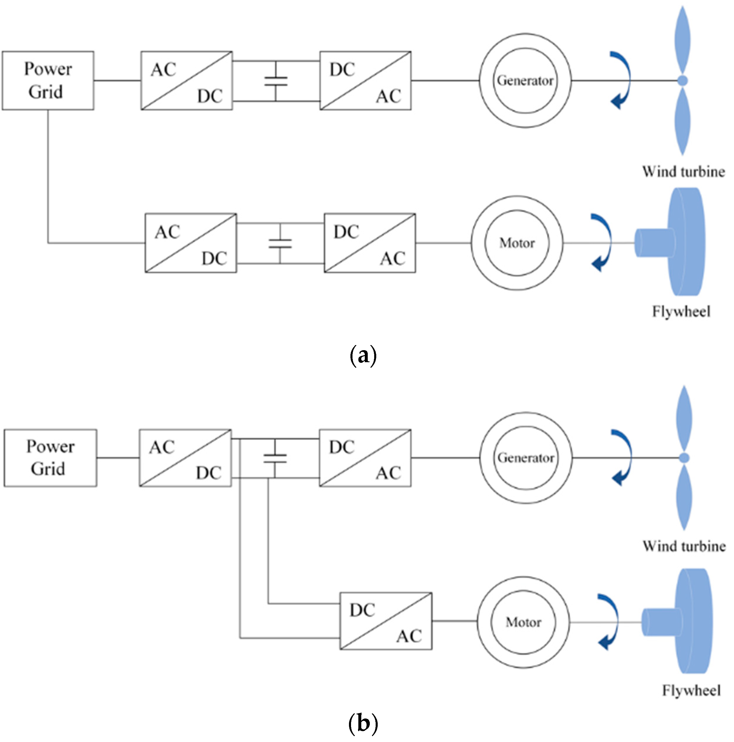
Figure 1. Electric schemes of flywheel connection to wind turbine. (a) Grid connection; (b) DC link connection.
Energies 17 03218 g001
Figure 2. Transmotor diagrams: (a) two-member topology; (b) three-member topology.
Energies 17 03218 g002
Figure 3. Configuration of the three-member transgenerator–flywheel system.
Energies 17 03218 g003
Figure 4. d-q axis frame determination of the transgenerator.
Energies 17 03218 g004
Figure 5. Torque analysis diagram.
Energies 17 03218 g005
Figure 6. Simplified torque analysis diagram.
Energies 17 03218 g006
Figure 7. Power flow diagram of the three-member machine.
Energies 17 03218 g007
Figure 8. Two-mass drivetrain model.
Energies 17 03218 g008
Figure 9. Dual two-mass drivetrain model of the transgenerator–flywheel system.
Energies 17 03218 g009
Figure 10. Flywheel SOC illustration.
Energies 17 03218 g010
Figure 11. Inner rotor control scheme (MPPT).
Energies 17 03218 g011
Figure 12. Outer rotor control scheme.
Energies 17 03218 g012
Figure 13. Rotor-side control diagram.
Energies 17 03218 g013
Figure 14. Grid-side control diagram.
Energies 17 03218 g014
Figure 15. Power curve of the wind turbine.
Energies 17 03218 g015
Figure 16. Verification of the rotor-side control. (a) Outer control loops; (b) inner control loops.
Energies 17 03218 g016
Figure 17. (a) Three-phase voltages and currents of the stator and inner rotor; (b) zoom-in waveforms at around 43 s.
Energies 17 03218 g017
Figure 18. Verification of the grid-side control. (a) Outer control loops; (b) inner control loops.
Energies 17 03218 g018
Figure 19. (a) Grid-side three-phase voltages and currents; (b) zoom-in waveforms at around 43.2 s.
Energies 17 03218 g019
Figure 20. Outer rotor torque command.
Energies 17 03218 g020
Figure 21. Outer rotor speed.
Energies 17 03218 g021
Figure 22. Power plots. First plot—electrical power generated from the wind turbine; second plot—mechanical power delivered by the inner rotor; third plot—mechanical power delivered by the outer rotor; fourth plot—total electrical power received by the transgenerator.
Energies 17 03218 g022
Table 1. Moment of inertia of disc flywheel and ring flywheel.
ShapeDescriptionMoment of Inertia
Energies 17 03218 i001Solid cylinder (or disk) of radius r. J = 1 2 m r 2
Energies 17 03218 i002Annular cylinder (or ring) of inner radius r1 and outer radius r2. J = 1 2 m r 1 2 + r 2 2
Table 2. Wind turbine parameters.
ParameterValue
Rated power2.12 MW
Blade length50 m
Blade inertia6 × 106 kg·m2
Rated wind speed10 m/s
Cut-in speed4 m/s
Cut-out speed25 m/s
Air density1.225 kg/m3
Table 3. Electrical parameters of the transgenerator.
ParameterValue
Rated stator voltage (line-to-line) 690   V r m s
Rated inner rotor voltage (line-to-line) 915   V r m s
Pole   pairs   number   p 3
Stator to inner rotor turns ratio1:1
Mutual   inductance   L m 2.6 mH
Inner   rotor   leakage   inductance   L σ i r 0.1 mH
Stator   leakage   inductance   L σ s 0.1 mH
Inner   rotor   resistance   R i r 1.5 × 10⁻³ Ω
Stator   resistance   R s 1.2 × 10⁻³ Ω
Outer   PM   rotor   flux   λ o r 2   W b
Table 4. Mechanical parameters of the transgenerator.
ParametersValue
System   1   inertia   J 1 3000 kg·m2
System   2   inertia   J 2 32,000 kg·m2
Rated Inner rotor torque32,739 N·m
Rated Outer rotor torque5300 N·m
Gear   ratio   N 1 45
Gear   ratio   N 2 10
Table 5. Flywheel parameters.
ParametersType/Value
ShapeRing
MaterialSteel
Density7850 kg/m3
Inner   radius   r 1 0.5 m
Outer   radius   r 2 0.6 m
Thickness   h 0.3624 m
Mass983.7 kg
Inertia   J f w 300 kg·m2
Table 6. Flywheel performance parameters.
ParametersValue
Outer rotor speed limit125 rad/s
Flywheel speed limit1250 rad/s (11,937 rpm)
Storage capacity65.1 kWh
Disclaimer/Publisher’s Note: The statements, opinions and data contained in all publications are solely those of the individual author(s) and contributor(s) and not of MDPI and/or the editor(s). MDPI and/or the editor(s) disclaim responsibility for any injury to people or property resulting from any ideas, methods, instructions or products referred to in the content.